the snl100-02 blade: advanced core material design studies
TRANSCRIPT

SANDIA REPORT SAND2013-10162 Unlimited Release Printed November 2013
The SNL100-02 Blade: Advanced Core Material Design Studies for the Sandia 100-
meter Blade D. Todd Griffith Prepared by Sandia National Laboratories Albuquerque, New Mexico 87185 and Livermore, California 94550
Sandia National Laboratories is a multi-program laboratory managed and operated by Sandia Corporation, a wholly owned subsidiary of Lockheed Martin Corporation, for the U.S. Department of Energy's National Nuclear Security Administration under contract DE-AC04-94AL85000. Approved for public release; further dissemination unlimited.

2
Issued by Sandia National Laboratories, operated for the United States Department of Energy by Sandia Corporation. NOTICE: This report was prepared as an account of work sponsored by an agency of the United States Government. Neither the United States Government, nor any agency thereof, nor any of their employees, nor any of their contractors, subcontractors, or their employees, make any warranty, express or implied, or assume any legal liability or responsibility for the accuracy, completeness, or usefulness of any information, apparatus, product, or process disclosed, or represent that its use would not infringe privately owned rights. Reference herein to any specific commercial product, process, or service by trade name, trademark, manufacturer, or otherwise, does not necessarily constitute or imply its endorsement, recommendation, or favoring by the United States Government, any agency thereof, or any of their contractors or subcontractors. The views and opinions expressed herein do not necessarily state or reflect those of the United States Government, any agency thereof, or any of their contractors. Printed in the United States of America. This report has been reproduced directly from the best available copy. Available to DOE and DOE contractors from U.S. Department of Energy Office of Scientific and Technical Information P.O. Box 62 Oak Ridge, TN 37831 Telephone: (865) 576-8401 Facsimile: (865) 576-5728 E-Mail: [email protected] Online ordering: http://www.osti.gov/bridge Available to the public from U.S. Department of Commerce National Technical Information Service 5285 Port Royal Rd. Springfield, VA 22161 Telephone: (800) 553-6847 Facsimile: (703) 605-6900 E-Mail: [email protected] Online order: http://www.ntis.gov/help/ordermethods.asp?loc=7-4-0#online

3
SAND2013-10162 Unlimited Release
Printed November 2013
The SNL100-02 Blade: Advanced Core Material Design Studies for the Sandia 100-
meter Blade
D. Todd Griffith Wind and Water Power Technologies Department
Sandia National Laboratories P.O. Box 5800
Albuquerque, New Mexico 87185-MS1124
Abstract A series of design studies are performed to investigate the effects of advanced core materials and a new core material strategy on blade weight and performance for large blades using the Sandia 100-meter blade designs as a starting point. The initial core material design studies were based on the SNL100-01 100-meter carbon spar design. Advanced core material with improved performance to weight was investigated with the goal to reduce core material content in the design and reduce blade weight. A secondary element of the core study was to evaluate the suitability of core materials from natural, re-growable sources such as balsa and recyclable foam materials. The new core strategy for the SNL100-02 design resulted in a design mass of 59 tons, which is a 20% reduction from the most recent SNL100-01 carbon spar design and over 48% reduction from the initial SNL100-00 all-glass baseline blade. This document provides a description of the final SNL100-02 design, includes a description of the major design modifications, and summarizes the pertinent blade design information. This document is also intended to be a companion document to the distribution of the NuMAD blade model files for SNL100-02 that are made publicly available.

4
ACKNOWLEDGMENTS The author wishes to thank the DOE Wind and Water Power Technology Office for the support to perform this work.

5
CONTENTS
Acknowledgments ......................................................................................................................................... 4
1. Introduction ............................................................................................................................................ 7
2. Advanced Core Material Design Studies For a 100-meter Blade ......................................................... 10 Industry Survey of Core Materials for Wind Turbine Blades ........................................................ 10 Summary of Design Changes Leading to SNL100-02 ................................................................... 11 Summary of Key Design Loads Analysis: Buckling .................................................................... 14 SNL100-02 Geometry .................................................................................................................... 16 SNL100-02 Materials..................................................................................................................... 18 SNL100-02 Laminate Schedule ..................................................................................................... 19 SNL100-02 Bill of Materials Analysis .......................................................................................... 23 SNL100-01 Span-wise Properties .................................................................................................. 24
3. Sandia Large Rotor Design Scorecard (SNL100-02) ........................................................................... 25
4. Description of Archived Blade Model Files for SNL100-02 ............................................................... 26
5. Concluding Remarks ............................................................................................................................ 27
6. References ............................................................................................................................................ 28
Distribution ................................................................................................................................................. 30
FIGURES Figure 1. Blade Mass Survey and Projections Versus Rotor Radius ........................................................... 8 Figure 2. Shear Modulus Versus Core Density (Balsa, PVC & PET Foam, Structured Core) ................... 11 Figure 3. Lowest Buckling Mode for SNL100-02 Occurring in Outboard Trailing Edge Panel at Frequency of 2.10 ...................................................................................................................................... 14 Figure 4. Buckling Mode Near the Root (closeup, right) at Frequency of 2.13 ......................................... 15 Figure 5. Two Views of the NuMAD Geometry for SNL100-00, SNL100-01, and SNL100-02 ............. 17 Figure 6. Selected Cross-section Plots for SNL100-02 .............................................................................. 21
TABLES Table 1. Blade Airfoil and Chord Properties for SNL100-00, SNL100-01, and SNL100-02..................... 16 Table 2. Material Property Data Selected from DOE/MSU Database [14] ................................................ 18 Table 3. Material Properties for Conceptual UD carbon laminate .............................................................. 18 Table 4. Material Properties for Additional Materials ................................................................................ 18 Table 5. Material Properties for Candidate Core Materials ........................................................................ 18 Table 6. Laminate Schedule for SNL100-02 (* indicates termination) ...................................................... 19 Table 7. Bill of Materials for SNL100-02 ................................................................................................... 23 Table 8. Materials Usage Summary for SNL100-02 .................................................................................. 23 Table 9. SNL100-02 Span-wise Blade Properties....................................................................................... 24 Table 10. Design Scorecard: Blade Parameters .......................................................................................... 25 Table 11. Design Scorecard: Blade Design Performance Metrics Summary ............................................. 25 Table 12. Design Scorecard: Blade Design Bill of Materials ..................................................................... 25 Table 13. SNL100-02 Blade Model Files Summary ................................................................................... 26

6

7
1. INTRODUCTION
Design and development of large wind turbine blades is challenging due to a variety of competing requirements related to economic, logistic, manufacturing, and technical constraints. Regarding the technical requirements, blade designs must satisfy deflection, buckling, fatigue, and stability requirements. This is a very challenging design problem, and one that becomes more challenging to do cost-effectively as designers pursue even longer blades designs. Sandia National Laboratories Wind and Water Power Technologies Department creates and evaluates innovative large blade concepts for horizontal axis wind turbines to promote designs that are more efficient aerodynamically, structurally, and economically. Recent work has focused on the development of a 100-meter blade for a 13.2 MW horizontal axis wind turbine and a series of large blade design studies for 100-meter blades. A link to the project website can be found in Reference 1. Through this work, several key design barriers for large blades have been identified and documented including panel buckling, weight growth & gravitational fatigue loading, and aero-elastic stability [2, 3].
In the present work, a series of design studies to evaluate new core material strategies are performed to address these technology barriers; of principal concern in this present work were panel buckling requirements and weight reduction. An overview of the blade design studies in this project are as follows, which started with an all-glass baseline design, followed by investigation of carbon fiber materials and now core materials:
All-glass Baseline Blade: SNL100-00 114 ton weight Reference 4
Carbon Design Studies: SNL100-01 74 ton weight Reference 5
Advanced Core Material: SNL100-02 59 ton weight Present Study
Advanced Geometry: SNL100-03 <50 ton weight Future Study
These designs are included in Figure 1 along with a survey of blade weights for commercial industry and research concept blades including the most recent data on new blades reported in the public domain. Note the Sandia SNL100-XX 100-meter series of designs (at 102.5-meter rotor radius in the figure), which demonstrates the weight reduction trajectory in this series of blade design studies. The industry survey includes recent large blades including the 73.5-meter (LM), 75-meter (Siemens), 83.5-meter (SSP/Samsung) and 81.6-meter (Euros/Mitsubishi) blades, which are plotted as diamonds in the figure. This data was gathered from web searches and is public domain. A few projections from 61.5-meter carbon blades are made in Figure 1 to project traditional and higher innovation weight growth to 102.5-meter rotor radius and beyond. The recent large blade data from industry indicates scaling between 2.0 and 2.5 being realized in actual designs, so a conservative projection for a 100-meter design with weight in the 50-60 ton range should be achievable although designs in the 40-50 ton range and lower should be possible through application of innovations. The design conditions and materials are largely unknown for these industry designs, thus this data provides a broad perspective of the industry blade designs rather than one particular technology approach or set of design conditions. For example, IEC design load classes and choices for spar material (i.e. glass versus carbon) and core materials, which have a very large effect on blade weights, vary a great deal across the industry commercial and prototype designs. The SNL 100-meter designs include parasitic and coating weights in order to provide more realistic blade weights. In addition to the diversity among these designs in terms of design class, material constraints, and manufacturing methods, some caution should be exercised as the blade costs and overall rotor economics (e.g. AEP) are not addressed here. Also, the more aggressive projections of weight reduction must assume that technical barriers can be overcome in

8
design. The extent to which these barriers can be overcome in a cost-effective way while maintaining weight targets is an important motivation for this study. Although not exercised in this work, a blade manufacturing cost tool was developed within this program of study to aid in answering economics and manufacturing related questions for large blades, as documented in References 6 and 7. This tool could be used to systematically reduce costs in a design optimization, which should be considered when sufficient materials cost data is available. This data was not available for this current study so the focus was structural performance and blade weight reduction.
Figure 1. Blade Mass Survey and Projections Versus Rotor Radius
The pre-design work in the Upwind 20MW turbine study resulted in a design with 126-meter rotor radius and a blade mass of 161,000 kg (Reference 8), which is also plotted in Figure 1. Similar to the Sandia All-glass Baseline Blade (SNL100-00) the Upwind 20MW blade design utilized only glass materials, and structural requirements on buckling necessitated a 3rd shear web. These choices contributed to both of these initial designs to have mass well above classical scaling exponent value of 3.0. A more recent concept design is the DTU Wind 10MW (at 89-meter radius in Figure 1) concept blade (Reference 9), which shows a weight growth exponent just under 2.5. Again, in this study, a series of design studies was performed to investigate the effect of advanced core materials and new core material strategies on blade weight and performance for large blades using the Sandia SNL100-01 carbon blade (Reference 5) as starting point. This report provides a description of the final blade design, termed as SNL100-02, which includes an updated core material strategy. This report includes a summary of the design modifications and a description of the NuMAD [10, 11] model files that are made publicly available. The same design process was once again used; therefore, prior work can be consulted for additional information that may be omitted in this design report. One key point is that all design requirements for the SNL100-02 design are also satisfied according to international blade design standards (IEC and GL, References 12 and 13); these requirements or drivers include maximum strains, tip-tower clearance,

9
buckling resistance, and fatigue life to demonstrate acceptance of the design concept to loads and safety factors from international design standards. The design safety factors and associated design standard are the same for this study as discussed in References 4 and 5. The new SNL100-02 blade can be included in the Sandia 13.2 MW reference turbine model by simply swapping the blade definition file. The Sandia 13.2 MW turbine model is documented in Reference 14, and is also publicly available by request on the project website noted in Reference 1.

10
2. ADVANCED CORE MATERIAL DESIGN STUDIES FOR A 100-METER BLADE
Selection of core materials is an important blade design decision with respect to manufacturing and design loads requirements. Blade designs require a significant amount of core material, and with increased blade length the buckling requirements and core materials requirements grow in importance [4, 15]. Core materials are used in several parts of the blade including in the trailing edge & leading edge panels, shear webs, along the trailing edge, and in some cases the spar caps. A cost-effective core strategy should involve using the correct type of core material in each of these parts of the blade requiring core material, again with consideration to manufacturing constraints and design loads requirements. Additional considerations, which are being more widely recognized, include recyclability and sustainability of core materials as enabled by recent development of new core materials. This section begins with an industry survey of blade core materials and concludes with results of blade design studies that investigate new core material strategies. The core material survey is intended to be a broad and representative survey of the types of core material solutions available in industry. Detailed study of a specific product could be a follow-on to this work in using the SNL100-02 blade specification as a reference design. Industry Survey of Core Materials for Wind Turbine Blades Blade designers have a large selection of core material types and core material suppliers from which to choose. One objective of this study is to investigate the suitability of different core materials for 100-meter length blade with respect to weight and buckling requirements. Fundamentally, the core material families include balsa, foam, and structured core materials. However, within each of these families, many product offerings are available including balsa of varying density, a wide variety of foams products (PVC, PET, and SAN formulations), and structured (engineered) core materials -- all available from multiple suppliers. The most important properties for core materials for blade applications are typically the shear modulus and density. Higher shear modulus is beneficial for improved buckling capacity and, of course, density is important to minimize blade weight. Cost and manufacturability are, of course, critical considerations, and Young’s modulus is also important as well. There is great diversity in foam properties provided in the various formulations. PVC foam has been the most common choice in blades, but recent developments in PET foams are making them viable options to consider for blades. A good overview of core materials for blades is provided in Reference 16. Figure 2 provides a comparison of the shear performance of various core materials for blades from a recent online search. Trend lines are included for the foam materials to provide a representative, quantitative comparison of these foam types as a function of density. Regarding the foam materials, clearly there is a loss of shear performance for the surveyed PET foams in comparison to PVC foams although the PET foams can offer several advantages including recyclability and novel processing/forming capabilities. End-grain balsa is the highest performing material in terms of shear modulus, while the surveyed structured core provides improvement over both foam types.

11
Figure 2. Shear Modulus Versus Core Density (Balsa, PVC & PET Foam, Structured Core) Another important consideration is that both the mechanical properties and weights/densities of core materials are significantly affected by considering dry (pre-infused) versus infused core properties. Typically only the dry material properties are available from material suppliers, and only dry properties are reported here with the exception of the structured core materials, which are infused. Use of infused properties accounts for both the performance improvement and the additional “parasitic” resin mass uptake during infusion – this is very important to consider in design calculations. Summary of Design Changes Leading to SNL100-02 The SNL100-01 carbon spar design (~74 ton weight) was the starting point for this design study. Again, the objective is to evaluate new core material choices and strategies by considering several advanced and relatively new core materials. The primary structural design objective is the traditional goal to address panel buckling while minimizing blade weight. As noted above, core material is utilized in many parts of a blade including the shear webs, trailing edge & leading edge panels, along the trailing edge, and in some designs in the spar caps. Given the wide variety of available core materials and the variation in required properties in each of these parts of the blade, a strategy utilizing two or more core material types should be considered to provide a weight optimal solution. This strategy is utilized here although a design trade study approach is taken -- systematic optimization would be valuable in future work, though. The primary considerations in the design iterations include the following:
requirements on shear modulus properties for core materials for buckling design placement of different core materials in various components of the blade including inboard versus
outboard placement to meet design requirements and reduce weight
y = 383374xR² = 0.9114
y = 240462xR² = 0.843
0.0E+00
2.0E+07
4.0E+07
6.0E+07
8.0E+07
1.0E+08
1.2E+08
1.4E+08
1.6E+08
1.8E+08
0 50 100 150 200 250
Shear M
odulus (Pa)
Density (kg/m^3)
Shear Modulus Versus DensityPVC Foam
PET Foam
StructuredCore (Infused)
Balsa
Linear (PVCFoam)
Linear (PETFoam)

12
A secondary consideration in the design included sustainable, recyclable, or re-growth capabilities of the core materials, that is, consideration of the material production method – more information on these issues can be found in References 17 and 18. The first step included choice of core material for inboard and outboard placement in the following areas:
Trailing edge reinforcement Trailing edge panel Leading edge panel Shear web(s) Spar caps
to replace the foam used in the initial SNL100-00 and SNL100-01 designs, which had average to below average shear modulus per weight (200 kg/m3 density, with 22 MPa shear modulus, and 256 MPa longitudinal Young’s Modulus, References 4 and 5). Clearly, in comparison to the core survey in the prior section, these properties are low at this density value in comparison to dry properties. These values, as originally adopted from the earlier UpWind large blade study for similarity, would appear to include the added resin (infused) weight in the density and infused improvement in Young’s modulus without the infused performance increase in shear modulus, which would be a conservative value. The design iterations in these studies are now discussed. The initial strategy was to replace the original foam material with balsa in the critical buckling areas, which shows very high shear properties per weight and is also a natural, sustainable material. In the less critical buckling areas, the use of a foam with lower density than balsa to save weight, but improved shear properties over the initial 200 kg/m3 foam, was considered. A key question here was which foam material to use. While no precise cost data is available for the materials considered in Figure 2, the question was simply recast as investigating the minimum performance requirements on buckling to see if the PET foam with lesser shear properties could be acceptable or if the higher performing PVC foam would be needed. Further, regarding the shear webs, trade-offs between balsa, PET foam, and structured core were considered. Initially, a design with structured core (in the shear webs), balsa (in the trailing edge and trailing edge panel), PET foam (in the leading edge panel) was evaluated. A summary of these core material properties is provided in Table 5. This resulted in an improvement in buckling capacity with weight reduction over the SNL100-01 design. Given the excess buckling design margin, it was attempted to remove the 3rd short shear web without repositioning the two principal webs. This resulted in a small (<2%) weight reduction and about a 20% reduction in buckling capacity in the trailing edge panel, which violated the design requirement. It was decided, for the purpose of this study, to return to the three shear web design approach and consider geometry and architecture optimization in future work so as to focus this effort on the effect of the core material choices. With the excess buckling design margin, PET foam was then attempted in the trailing and leading edge regions with very small weight reduction due to the increased thickness required of the lower performing PET foam. This analysis was very useful to clearly identify the critical high buckling regions of the blade as well as the regions of the blade that were satisfactory using the PET foam. This was used to determine the span-wise location to which buckling was critical inboard so that the highest performing balsa core could be used inboard with the lower density PET foam placed outboard. Balsa was applied along the entire trailing edge reinforcement and in the trailing edge panel out to 43.9 meter span. PET foam was applied from 43.9 meter span and outboard in the trailing edge panel and along the entire leading edge panel.

13
Of course, PVC foam with higher shear properties per density could provide a small reduction in blade weight with thinner core, and this could be the focus of future work considering weight and cost optimal designs and/or manufacturing considerations using the SNL Blade Manufacturing Cost Tool (References 6 and 7); for example. This type of core design optimization was outside the scope of this study as the required materials cost data, which is closely guarded by suppliers, was not available. The decision to use PET foam here was weighted toward a more conservative approach showing that the lower-performing foam could provide a suitable solution in the less critical buckling areas (outboard panels and shear webs); while, the higher performing balsa core was needed in the critical buckling areas. This basic strategy of inboard balsa and outboard PET foam was continued in several design iterations focused on sizing of the core thickness to mitigate panel buckling, trailing edge buckling, and shear web buckling while reducing weight. The final iterations included a consideration of balsa or PET foam to replace the structured core in the shear webs. Of course, structural performance and cost are both important, but without actual material pricing data, the focus had to be on structural performance and weight reduction. In the end, based on analysis, the PET foam was deemed suitable from a structural design point of view for the shear web core, which is not a surprise as it has shear properties similar to the foam used in the initial SNL100-00 and SNL100-01 studies. These changes in the core material choices and their placement resulted in approximately 8% blade weight reduction from the SNL100-01 design. With small excess buckling margins and significant excess fatigue life in the spar and trailing edge, it was decided to evaluate secondary weight reduction through reducing the thickness of the triaxial material designed on the interior and exterior of the entire blade surface. This is a major component of the total blade weight, and in reducing the thickness of these layers by 20% from 5mm to 4 mm an additional 6% weight reduction from found compared to SNL100-01. Through the triaxial reduction, buckling margins were negatively affected, but only small increases in core thicknesses were needed to satisfy them along with the triax material thickness reduction. Due to the weight reduction of both the core and triaxial materials, the gravitational design loads were reduced allowing additional modest mass reductions in trailing edge reinforcement and the carbon spar caps. Assumed parasitic resin was reduced from 4mm to 3mm to maintain an approximate 7% parasitic added mass percentage in the design, which resulted in additional reduction in the design weight. The major take-ways of these SNL100-02 design studies include:
The final design weight was 59 tons, which was about 20% reduction from SNL100-01 (carbon spar) and more than 48% reduction from SNL100-00 (all-glass baseline) – meeting all design loads requirements as detailed in the next section
This is intended to be a baseline for comparison of alternative core strategies and core material choices, not a systematically optimized concept for a 100-meter blade
New, advanced core material choices showed primary and secondary improvements in weight reduction: the final strategy involved use of two materials with balsa in critical buckling areas (inboard in the trailing edge panels and along the trailing edge reinforcement) and PET foam in the less critical buckling areas (in the shear webs, leading edge panel, and outboard in the trailing panel)
These material choices offer ability to re-grow (balsa) or recycle (PET foam) while reducing weight and meeting challenging large blade performance requirements
The improved core performance aided in reducing triaxial laminate requirements, and overall weight reduction reduced trailing edge reinforcement needs; further assumed parasitic resin mass was reduced
14
Return to a two shear web solution might be possible through further design studies in using higher performing core materials, although the removal of the short third web showed only a minor weight decrease
Core optimization/sizing would be a next step in this design including both performance and costs for materials and manufacturing – industry core material pricing data would be required
Further, the effect of design loads class if very important. This was an IEC Class I design. Significant reductions in loads and structural requirements/weight could be achieved if lower design class is used along with a corresponding control system and operations strategy.
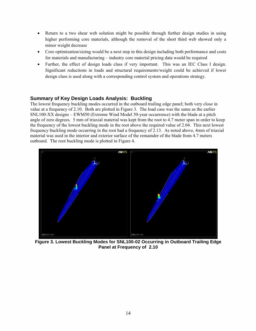
Summary of Key Design Loads Analysis: Buckling The lowest frequency buckling modes occurred in the outboard trailing edge panel; both very close in value at a frequency of 2.10. Both are plotted in Figure 3. The load case was the same as the earlier SNL100-XX designs – EWM50 (Extreme Wind Model 50-year occurrence) with the blade at a pitch angle of zero degrees. 5 mm of triaxial material was kept from the root to 4.7 meter span in order to keep the frequency of the lowest buckling mode in the root above the required value of 2.04. This next lowest frequency buckling mode occurring in the root had a frequency of 2.13. As noted above, 4mm of triaxial material was used in the interior and exterior surface of the remainder of the blade from 4.7 meters outboard. The root buckling mode is plotted in Figure 4.
Figure 3. Lowest Buckling Modes for SNL100-02 Occurring in Outboard Trailing Edge
Panel at Frequency of 2.10

15
Figure 4. Buckling Mode Near the Root (closeup, right) at Frequency of 2.13

16
SNL100-02 Geometry As noted, the external geometry for SNL100-02 is the same as that of the baseline SNL100-00 and SNL100-01 designs. In Table 1, the key external geometry information is summarized for convenience. Two views of the NuMAD [10, 11] geometry as plotted in Figure 5.
Table 1. Blade Airfoil and Chord Properties for SNL100-00, SNL100-01, and SNL100-02 Note: Thickness to chord ratio in parentheses for transition and modified outboard airfoils
Station Number
Blade Fraction Chord (m) Twist (deg)Pitch Axis (Fraction)
Airfoil Description
1 0.000 5.694 13.308 0.500 Cylinder
2 0.005 5.694 13.308 0.500 Cylinder
3 0.007 5.694 13.308 0.500 Transition (99.25%)
4 0.009 5.694 13.308 0.500 Transition (98.5%)
5 0.011 5.694 13.308 0.500 Transition (97.75%)
6 0.013 5.694 13.308 0.500 Ellipse (97%)
7 0.024 5.792 13.308 0.499 Ellipse (93.1%)
8 0.026 5.811 13.308 0.498 Ellipse (92.5%)
9 0.047 6.058 13.308 0.483 Transition (84%)
10 0.068 6.304 13.308 0.468 Transition (76%)
11 0.089 6.551 13.308 0.453 Transition (68%)
12 0.114 6.835 13.308 0.435 Transition (60%)
13 0.146 7.215 13.308 0.410 Transition (51%)
14 0.163 7.404 13.177 0.400 Transition (47%)
15 0.179 7.552 13.046 0.390 Transition (43.5%)
16 0.195 7.628 12.915 0.380 DU99-W-405
17 0.222 7.585 12.133 0.378 DU99-W-405 (38%)
18 0.249 7.488 11.350 0.377 DU99-W-350 (36%)
19 0.276 7.347 10.568 0.375 DU99-W-350 (34%)
20 0.358 6.923 9.166 0.375 DU97-W-300
21 0.439 6.429 7.688 0.375 DU91-W2-250 (26%)
22 0.520 5.915 6.180 0.375 DU93-W-210 (23%)
23 0.602 5.417 4.743 0.375 DU93-W-210
24 0.667 5.019 3.633 0.375 NACA-64-618 (19%)
25 0.683 4.920 3.383 0.375 NACA-64-618 (18.5%)
26 0.732 4.621 2.735 0.375 NACA-64-618
27 0.764 4.422 2.348 0.375 NACA-64-618
28 0.846 3.925 1.380 0.375 NACA-64-618
29 0.894 3.619 0.799 0.375 NACA-64-618
30 0.943 2.824 0.280 0.375 NACA-64-618
31 0.957 2.375 0.210 0.375 NACA-64-618
32 0.972 1.836 0.140 0.375 NACA-64-618
33 0.986 1.208 0.070 0.375 NACA-64-618
34 1.000 0.100 0.000 0.375 NACA-64-618

17
Figure 5. Two Views of the NuMAD Geometry for SNL100-00, SNL100-01, and SNL100-02

18
SNL100-02 Materials Table 2, Table 3, and Table 4 list the materials and their properties for the SNL100-02 design, which are unchanged from the earlier design studies. The densities for the glass laminates in Table 2 are 1920, 1780, and 1850 kg/m3 for the uni-directional, double bias, and triaxial materials, respectively. Core material properties considered in these design studies are listed in Table 5. The modulus in the thickness direction and the shear moduli associated with the thickness direction were modeled as having the same values as noted in the table for both E and G for all core materials. For comparison, based on the industry survey, a representative PVC foam of the same density as the PET foam (100 kg/m3) would appear to have similar Young’s Modulus but significantly higher shear modulus in comparison to the PET foam.
Table 2. Material Property Data Selected from DOE/MSU Database [19]
Laminate Definition Longitudinal Direction
ShearElastic Constants Tension Compression
VARTM Fabric/resin lay-up VF
%EL
GPa ET
GPaυLT
GLT GPa
UTSL
MPaεmax %
UCSL MPa
εmin %
τTU MPa
E-LT-5500/EP-3 [0]2 54 41.8 14.0 0.28 2.63 972 2.44 -702 -1.53 30
Saertex/EP-3 [±45]4 44 13.6 13.3 0.51 11.8 144 2.16 -213 -1.80 ----
SNL Triax [±45]2[0]2 --- 27.7 13.65 0.39 7.2 ---- ---- ---- ---- ---- EL – Longitudinal modulus, υLT – Poisson’s ratio, GLT and τTU – Shear modulus and ultimate shear stress. UTSL – Ultimate longitudinal tensile strength, εMAX – Ultimate tensile strain, UCSL – Ultimate longitudinal compressive strength. ΕMIN – Ultimate compressive strain.
Table 3. Material Properties for Conceptual UD carbon laminate Value
Density (kg/m3) 1220 EL (GPa) 114.5 ET (GPa) 8.39
GLT (GPa) 5.99 υLT 0.27
Table 4. Material Properties for Additional Materials
Material EL GPa
ET GPa
GLT GPa
υLT Density (kg/m3)
GelCoat 3.44 3.44 1.38 0.3 1235 Resin 3.5 3.5 1.4 0.3 1100
Table 5. Material Properties for Candidate Core Materials
Material EL MPa
ET MPa
GLT MPa
υLT Density (kg/m3)
Foam (baseline) 256 256 22 0.3 200 Representative Balsa 50 50 175 -- 155
Representative PVC Foam
~106 ~106 38 -- 100
Representative PET Foam
106 106 24 -- 100
Representative Structured Core
(infused) 140 140 60 -- 110

19
SNL100-02 Laminate Schedule Table 6 shows the laminate schedule for SNL100-02. Note that in the trailing edge reinforcement (“TE Reinforcement”) the glass uniaxial material and balsa are listed together as the glass uniaxial thickness is provided in the first number and the balsa thickness provided after the comma. Also note that the trailing edge aft panel is divided into inboard and outboard sections with balsa terminating and PET foam beginning at the 43.9 meter span location. This data is also provided in NuMAD.xlsx spreadsheet.
Table 6. Laminate Schedule for SNL100-02 (* indicates termination)
Station Number
Blade Span
Root Buildup
Spar Cap TE
Reinforcement LE Panel TE (Aft) Panel
Triax/EP-3 Conceptual
Carbon E-LT-5500/EP-3,
Balsa PET Foam
Balsa Inboard
PET Foam
Outboard
(-) (mm) (mm) (mm) (mm) (mm) (mm)
1 0.000 96
2 0.005 77 1
3 0.007 66 2
4 0.009 55 2
5 0.011 44 3 6 0.013 39 7 1 1
7 0.024 35 9 3.5 3.5 8 0.026 31 9 13 13 9 0.047 31 13 30 55
10 0.068 31 19 40 55
11 0.089 20 32 15, 65 40 55
12 0.114 15 43 15, 65 40 55
13 0.146 10 69 15, 65 40 55
14 0.163 5 69 20, 65 40 55
15 0.179 1 74 20, 65 40 55 16 0.195 * 85 20, 65 40 55 17 0.222 85 20, 65 40 55 18 0.249 85 20, 65 40 50
19 0.276 80 15, 65 40 50 20 0.358 80 15, 60 40 50 21 0.439 80 0, 40 40 * 40 22 0.521 80 0, 20 40 40
23 0.602 75 0, 10 40 40
24 0.667 70 0, 10 40 40
25 0.683 65 0, 10 40 40 26 0.732 55 0, 10 40 40
27 0.765 40 0, 10 30 30
28 0.846 20 0, 10 15 15 29 0.895 15 0, 10 10 10
30 0.944 10 0, 10 5 5
31 0.957 10 0, 10 5 5
32 0.972 10 0, 10 5 5
33 0.986 10 0, 10 5 5
34 1.000 * * * *

20
In addition to the detailed span-wise layup data in Table 6, the entire blade internal and external surfaces have 4 mm of triaxial material outboard of the 4.7 meter span, which is a 20% reduction from the SNL100-00 and SNL100-01 blade designs. From the root to 4.7 meters, 5 mm of triaxial material was maintained as it was needed to satisfy buckling requirements in the root section. Extra parasitic mass is included by modeling 3 mm of epoxy resin on the internal blade surface; this value was reduced from 4 mm in the SNL100-01 blade in order maintain roughly the same percentage of parasitic mass (~7%). The external surface includes 0.6 mm of gelcoat (surface paint), which was again unchanged. Again, the inclusion of extra epoxy resin and surface gelcoat are included to produce a more realistic blade design weight, as noted below they total more than 8% of the blade weight. The core material was changed in all three shear webs to PET foam, although the same layup was used for SNL100-02: 60 mm of PET foam sandwiched between 3 mm of double bias material (Saertex/EP-3) on the outer surfaces. Cross sections are plotted for key stations along the span in Figure 6. The thickness representation is true scale for each of the shell elements about the station. The coloring is by section number. Note that the root section is composed of multiple sections in this model although the layup properties are the same for each section of the uniform root according to Table 6. A better understanding of these plots involves interpreting them with the detailed layup schedule from either Table 6 or the NuMAD spreadsheet as a reference aid.

21
(a) 0.0 meters (root circle) (b) 2.4 meters (principal webs begin)
(c) 8.9 meters (transition) (d) 11.4 meters
(e) 14.6 meters (third web begins) (f) 16.3 meters
Figure 6. Selected Cross-section plots for SNL100-02

22
(g) 19.5 meters (maximum chord) (h) 35.8 meters
(i) 60.2 meters (third web ends) (j) 73.2 meters
(k) 94.3 meters (principal webs end) (l) 97.2 meters
Figure 6. Selected Cross-section plots for SNL100-02 (cont’d)

23
SNL100-02 Bill of Materials Analysis For the six materials used in this design, listed above, their contribution to the total blade weight was calculated using PreComp [20]. Based on using the FAST code, the total blade weight is 59,047 kg. This analysis was performed for individual laminates and also the traditional bill of materials summary. The bill of materials summary is provided first in Table 7. Here quantities of dry fibers and resin are computed separately, with the exception of the carbon prepreg material. The resin weight includes only the infused resin, which includes the parasitic resin, but not the resin in the prepreg. The most notable changes from the SNL100-01 are the reduction in core materials and reduction in triaxial material.
Table 7. Bill of Materials for SNL100-02
Material Description Mass (kg) Percent Blade Mass
E-LT-5500 Uni-directional Fiberglass 8,964 15.2%
Saertex Double Bias Fiberglass 8,706 14.7%
Carbon Prepreg Conceptual Laminate 10,103 17.1%
EP-3 Infused Resin 22,836 38.7%
Balsa Balsa Core 2,625 4.4%
PET Foam Foam Core 4,883 8.3%
Gelcoat Coating 925 1.6%
Table 8 provides an analysis of the laminate usage in the design along with total mass and percentage of total blade mass. This provides an assessment of material usage in the various blade components. The table shows that only 2.1% of the blade weight is composed of uni-directional glass laminates used in trailing edge reinforcement, which is a slight reduction from SNL100-01. The carbon spar caps are 17.1% of the blade weight, which is an increase although in an absolute sense there was very small change from SNL100-01. By far, the largest contributor to blade weight is the triaxial laminates in the root buildup and skins with 52% of the blade weight. The extra (parasitic) resin accounts for 4,120kg of the blade weight while the gelcoat accounts for 925 kg. In total, the inclusion of extra resin and gelcoat comprise 8.6% of the total blade weight.
Table 8. Materials Usage Summary for SNL100-02 Material Usage/Location Mass (kg) Percent Blade Mass
E-LT-5500/EP-3 Trailing edge 1,260 2.1% Carbon Prepreg Spar cap 10,103 17.1% SNL Triax/EP-3 Root build-up, internal & external surfaces 30,680 52.0%
Balsa Core panels 2,625 4.4% PET Foam Core panels, shear webs 4,883 8.3%
Resin (parasitic) Extra weight (interior surface) 4,120 7.0% Saertex/EP-3 Shear webs 4,446 7.5%
Gelcoat Coating 925 1.6%

24
SNL100-02 Span-wise Properties Blade span-wise properties were calculated using the PreComp [20] as implemented within the NuMAD v2.0 Matlab-based graphical user interface. Table 9 lists the blade span-wise properties including flap- and edge-wise EI, EA, GJ, and mass distributions. Additional span-wise information (e.g. airfoil and chord schedules) can be found above or in the file package for SN100-02. The data in Table 9 is also found in the FAST blade input file as described in Table 13.
Table 9. SNL100-02 Span-wise Blade Properties Station
Number Span Fraction mass_den flp_stff edge_stff tor_stff axial_stff flp_iner edge_iner
(-) (-) (kg/m) (N-m^2) (N-m^2) (N) (N-m^2) (kg-m) (kg-m) 1 0 3600 2.10E+11 2.07E+11 1.08E+11 5.31E+10 14260 14070 2 0.005 2970 1.75E+11 1.72E+11 8.98E+10 4.38E+10 11850 11680 3 0.007 2596 1.53E+11 1.50E+11 7.80E+10 3.83E+10 10270 10220 4 0.009 2223 1.29E+11 1.28E+11 6.63E+10 3.27E+10 8710 8767 5 0.011 1854 1.08E+11 1.06E+11 5.48E+10 2.74E+10 7204 7318 6 0.013 1692 1.02E+11 9.62E+10 4.96E+10 2.55E+10 6525 6646 7 0.024 1744 9.56E+10 9.06E+10 4.53E+10 2.48E+10 6262 6306 8 0.026 1628 8.81E+10 8.32E+10 4.14E+10 2.28E+10 5815 5860 9 0.047 1601 8.10E+10 8.32E+10 3.84E+10 2.24E+10 5269 6021 10 0.068 1612 7.91E+10 8.79E+10 3.71E+10 2.34E+10 4847 6400 11 0.089 1365 6.72E+10 8.19E+10 2.67E+10 2.17E+10 3481 5909 12 0.114 1195 5.74E+10 7.35E+10 1.99E+10 2.09E+10 2577 5331 13 0.146 780.5 4.68E+10 4.13E+10 6.88E+09 1.80E+10 1345 3233 14 0.163 765 4.04E+10 4.35E+10 5.66E+09 1.80E+10 1112 3301 15 0.179 747.3 3.64E+10 4.12E+10 4.39E+09 1.87E+10 929.4 3196 16 0.195 750.3 3.54E+10 4.07E+10 3.38E+09 2.05E+10 811.6 3140 17 0.222 735.4 3.06E+10 3.98E+10 2.96E+09 2.03E+10 695.7 3042 18 0.249 710.8 2.63E+10 3.78E+10 2.47E+09 2.02E+10 581.7 2845 19 0.276 672.7 2.13E+10 3.22E+10 2.08E+09 1.89E+10 476.9 2537 20 0.358 624.9 1.44E+10 2.70E+10 1.34E+09 1.85E+10 305.9 2065 21 0.439 522.2 9.43E+09 1.40E+10 8.13E+08 1.74E+10 188.5 1257 22 0.520 479.8 6.12E+09 1.09E+10 5.19E+08 1.70E+10 118.5 940.3 23 0.602 433.9 3.91E+09 8.41E+09 3.30E+08 1.58E+10 74.47 701.8 24 0.667 388 2.49E+09 6.62E+09 2.18E+08 1.47E+10 47.45 539.2 25 0.683 372.3 2.12E+09 6.21E+09 1.95E+08 1.38E+10 41.1 505.5 26 0.732 337 1.53E+09 5.13E+09 1.52E+08 1.19E+10 30.5 416.1 27 0.764 292.2 1.08E+09 4.40E+09 1.36E+08 9.17E+09 23.91 351.1 28 0.846 221.6 4.90E+08 2.96E+09 9.74E+07 5.47E+09 13.73 231.8 29 0.894 195.2 3.30E+08 2.30E+09 7.68E+07 4.45E+09 10.13 178.7 30 0.943 147.3 1.37E+08 1.11E+09 3.67E+07 3.17E+09 4.513 85.06 31 0.957 111 7.96E+07 6.55E+08 2.14E+07 2.60E+09 2.477 48.59 32 0.972 85.79 3.58E+07 3.02E+08 9.57E+06 2.01E+09 1.109 22.42 33 0.986 56.44 9.53E+06 8.58E+07 2.53E+06 1.32E+09 0.294 6.365 34 1.000 4.672 3.32E+03 4.45E+04 1.16E+03 1.09E+08 0 0.003

25
3. SANDIA LARGE ROTOR DESIGN SCORECARD (SNL100-02) Design scorecard summary for SNL100‐02 100‐meter blade. Significant design changes from the SNL100‐01 blade (see report SAND2013‐1178) include: (1) balsa and PET foams introduced using new core strategy with balsa in high propensity buckling areas and foam elsewhere, (2) 20% reduction in skin triaxial material thickness, (3) trailing edge uni‐axial glass reinforcements were slightly reduced in thickness, (4) parasitic resin thickness reduced from 4mm to 3 mm.
Table 10. Design Scorecard: Blade Parameters Parameter Value
Blade Designation (name) SNL100-02 Design Wind Speed Class IB
Blade Length (m) 100 Blade Weight (kg) 59,047
Span-wise CG location (m) 31.95 # shear webs 3
Maximum chord (m) 7.628 (19.5% span) Lowest fixed base natural
frequency (Hz) 0.55 Hz (NuMAD/ANSYS)
Control Variable speed; collective pitch Special notes: Updated design with new core material strategy, carbon spar design, started design
with SNL100-01; 7.0% of blade weight is parasitic/extra weight (resin)
Table 11. Design Scorecard: Blade Design Performance Metrics Summary
Analysis Design Load
Condition (DLC) designation
Metrics Notes/method
Fatigue Turbulent Inflow
(NTM) (4 to 24 m/s)
182 years fatigue life at 50% span in spar 646 years fatigue life at 15% span in spar 352 years fatigue life at 15% span in TE
MSU/DOE Database provided single cycle failure values and GL was
referenced for slope values (10 for glass and 14 for carbon); Miner’s Rule
calculation
Ultimate EWM50;
0 degree pitch with 5 degree yaw error
Max strain = 3055 micro-strain Allowable strain = 5139 micro-strain
Max/allowable = 59.4%
At 11% span (near root); flap-wise; FAST
Deflection ECD-R Max (10.51 m) vs. allowable (13.67 m );
Clearance = 3.16 m = 23.1% FAST, NuMAD/ANSYS
Buckling EWM50; 0 degree pitch
Min load factor ( 2.100 ) vs. allowable ( 2.042 );
near root to 5 meters span-wise Linear, ANSYS
Flutter -- Flutter margin 1.71 (@ 12.7 RPM) Sandia NuMAD-based
Flutter Tool (BLAST); updated tool since SNL100-00 calculations
Table 12. Design Scorecard: Blade Design Bill of Materials
Material Description Mass (kg) Percent Blade Mass
E-LT-5500 Uni-directional Fiberglass 8,964 15.2%
Saertex Double Bias Fiberglass 8,706 14.7%
Carbon Prepreg Conceptual Laminate 10,103 17.1%
EP-3 Infused Resin 22,836 38.7%
Balsa Balsa Core 2,625 4.4%
PET Foam Foam Core 4,883 8.3%
Gelcoat Coating 925 1.6%

26
4. DESCRIPTION OF ARCHIVED BLADE MODEL FILES FOR SNL100-02
The blade model file package for SNL100-02 includes both the NuMAD [10, 11] blade design files and input files for ANSYS [21] generated by NuMAD. The blade was designed using NuMAD (version 2.0) and analyzed using ANSYS (version 14.0). Table 13 provides a summary of the available model files. Please note that the *.mac files, which are distributed with NuMAD, are also included in this blade file package for convenience as they are needed when reading the *.src files into ANSYS.
Table 13. SNL100-02 Blade Model Files Summary Filename Usage Description
NuMAD.xlsx Primary input file for Matlab-
based NuMAD Code (NuMAD v2.0)
Spreadsheet blade model data including detailed blade geometry, materials, and
layup information
SNL100-02.nmd NuMAD model file Produced using NuMAD v2.0 with input
from NuMAD.xlsx spreadsheet
MatDBsi.txt NuMAD materials database Contains material/laminate property
information
SNL100-02_FASTBlade_precomp.dat
Can be used with SNL13.2MW FAST turbine
model for aeroelastic simulations and design loads
analysis
FAST blade file for SNL100-02; Produced using NuMAD v2.0
“airfoils” folder NuMAD airfoil geometry
coordinates Contains a set of files with coordinates for
blade cross section geometries
“docs” folder documentation Contains associated documents including
most of the references to this report
SNL100-02.src NuMAD output file; ANSYS
model input file Text file formatted for input to ANSYS to
generate a finite element model
master.db ANSYS database file Created using SNL100-02.src input to
ANSYS SNL100-02.p3d Blade external geometry file Plot 3D file format
The NuMAD input files are useful to investigate blade re-design efforts (e.g. changes in material selection and placement or changes in geometry). NuMAD can produce two types of input files for ANSYS, which include the text input file (*.src) and the ANSYS database file (*.db). A complete set of files for NuMAD and ANSYS is included so that the blade data can be verified by reproduction and also so that modified design solutions can be compared with the provided SNL100-02 design. The provided files should provide multiple paths for verification of blade model data. For example, SNL100-02.src can be read directly into ANSYS to produce the SNL100-02 finite element model (e.g. “/input, SNL100-02, src”).

27
5. CONCLUDING REMARKS A few observations are made on the blade parameters and analysis of the SNL100-02 advanced core material blade. The primary design objectives in selecting new core materials along with a new core design strategy included satisfying buckling requirements and reducing blade weight, although a secondary objective was to investigate the performance of sustainable and recyclable core materials. Balsa and PET foam, which offer re-growth (balsa) and recycling (PET foam) capabilities, were found to provide satisfaction of buckling requirements while reducing blade weight. The design weight for SNL100-02 is 59 tons and the resulting mass scaling factor (exponent) for this design is less than 2.5. The same comparison for the SNL100-00 all-glass baseline blade yielded a mass scaling factor of over 3.0 while the SNL100-01 carbon blade was just under 3.0. SNL100-02 is a 20% reduction in weight from the most recent SNL100-01 design and over 48% reduction in weight from the initial SNL100-00 baseline. In terms of material usage, about 12% of the SNL100-02 blade weight is core material, which was a reduction of nearly 50% with the current materials selection and new core strategy using balsa and PET foam. The parasitic weight assumed in the design was over 4 tons (~7%) for SNL100-02. Without the added weight for extra resin and coating, the design weight would be about 54 tons. The flutter speed was negatively impacted with a 7% reduction in flutter speed in comparison to the previous SNL100-01 design. As was the case with the prior SNL100-XX series designs, SNL100-02 can be used as a reference blade for both performance and cost studies. While this study focused on structural performance and weight reduction, future work could involve using this reference design as a basis for blade cost studies and evaluation of the performance, weight and cost impacts of alternative core materials.

28
6. REFERENCES
1. “Offshore Wind: Sandia Large Rotor Development,” Sandia 100-meter Blade Research Website: http://largeoffshorerotor.sandia.gov, Last modified 18-February-2013; accessed 01-October-2013.
2. Griffith, D.T., Resor, B.R., and Ashwill, T.D., “Challenges and Opportunities in Large Offshore Rotor Development: Sandia 100-meter Blade Research,” AWEA WINDPOWER 2012 Conference and Exhibition; Scientific Track Paper; Atlanta, GA; June 3-6, 2012.
3. Griffith, D.T., “Large Rotor Development: Sandia 100-meter Blade Research,” Invited Presentation: AMI Wind Turbine Blade Manufacture 2012, Dusseldorf, Germany, November 28, 2012, Slide Documentation: Sandia Technical Report Number: SAND2012-8790C.
4. Griffith, D.T. and Ashwill, T.D., “The Sandia 100-meter All-glass Baseline Wind Turbine Blade: SNL100-00,” Sandia National Laboratories Technical Report, SAND2011-3779, June 2011.
5. Griffith, D.T., “The SNL100-01 Blade: Carbon Design Studies for the Sandia 100-meter Blade,” Sandia National Laboratories Technical Report, SAND2013-1178, February 2013.
6. Griffith, D.T. and Johanns, W., “Large Blade Manufacturing Cost Studies Using the Sandia Blade Manufacturing Cost Tool and Sandia 100-meter Blades,” Sandia National Laboratories Technical Report, April 2013, SAND2013-2734.
7. Johanns, W. and Griffith, D.T., “User Manual for Sandia Blade Manufacturing Cost Tool: Version 1.0,” Sandia National Laboratories Technical Report, April 2013, SAND2013-2733.
8. Peeringa, J., Brood, R., Ceyhan, O., Engels, W., and Winkel, G., “Upwind 20MW Wind Turbine Pre-Design: Blade Design and Control,” Energy research Centre of the Netherlands (ECN) Technical Report, ECN-E—11-0017, December 2011.
9. Bak, Christian et al. "Light Rotor: The 10-MW reference wind turbine". Proceedings of EWEA 2012 - European Wind Energy Conference & Exhibition. EWEA - The European Wind Energy Association. 2012.
10. Laird, D. and T. Ashwill, “Introduction to NuMAD: A Numerical Manufacturing and Design Tool,” Proceedings of the ASME/AIAA Wind Energy Symposium, Reno, NV, 1998, pp. 354-360.
11. Berg, J.C. and B.R. Resor, “Numerical Manufacturing And Design Tool (NuMAD v2.0) for Wind Turbine Blades: User’s Guide,” Sandia National Laboratories Technical Report, SAND2012-7028.
12. International Electrotechnical Commission (IEC) Design Standard, IEC 61400-1 Ed.3: Wind turbines - Part 1: Design requirements.
13. Germanischer-Lloyd (GL) Design Standard, Guideline for the Certification of Wind Turbines Edition 2010.
14. Griffith, D.T. and Resor, B.R., “Description of Model Data for SNL13.2-00-Land: A 13.2 MW Land-based Turbine Model with SNL100-00 Blades,” Sandia National Laboratories Technical Report, SAND2011-9310P, December 2011.
15. Jensen, F., “Scale-up of Wind Turbine Blades – Changes in Failure Type,” Bladena Technical Report (http://www.bladena.com/getattachment/Publications/SCALE-UP-OF-WIND-TURBINE-BLADES.pdf.aspx), last accessed 7-November 2013.
16. “Core for Composites: Wind of Change,” CompositesWorld Online: http://www.compositesworld.com/articles/core-for-composites-winds-of-change; Posted June 2010, Last Accessed October 2013.
17. Larsen, K., “Recycling wind,” Reinforced Plastics, Online: http://www.reinforcedplastics.com/view/319/recycling-wind/, 31 January, 2009, Last Accessed 7 November 2013.
18. Yang, Y., et al., “Recycling of Composite Materials,” Chem. Eng. Process. (2011), doi:10.1016/j.cep.2011.09.007
19. “DOE / MSU COMPOSITE MATERIAL FATIGUE DATABASE,” March 31, 2010, Version 19.0, J.F. Mandell, D.D. Samborsky, Sandia Technical Report: SAND97-3002.

29
20. NWTC Design Codes (PreComp by Gunjit Bir). http://wind.nrel.gov/designcodes/preprocessors/precomp/. Last modified 26-March-2007; accessed 26-March-2007.
21. ANSYS finite element software, http://www.ansys.com. Last accessed 06-December-2011.
30
DISTRIBUTION 1 MS0899 Technical Library 9536 (electronic copy)

(page intentionally left blank)
