the secarb anthropogenic test: status from the field
TRANSCRIPT

Available online at www.sciencedirect.com
Energy Procedia 00 (2013) 616.00
www.elsevier.com/locate/procedia
GHGT-11
The SECARB Anthropogenic Test: Status from the Field
George J. Koperna, Jr.a*, Vello Kuuskraaa, David Riestenberga, Richard Rhudyb, Robert Trautzb, Dr. Gerald Hillc, and Dr. Richard Espositod
aAdvanced Resources International, Inc., 4501 Fairfax Drive, Suite #910, Arlington, VA 22203 USA
b Electric Power Research Institute, 3412 Hillview Ave., Palo Alto, CA 94304 USA
c Southern States Energy Board, 6325 Amherst Court, Norcross, Georgia 30092 USA
d Southern Company, 600 N. 18th St., 14N-8199, Birmingham, AL 35291 USA
Abstract The United States Department of Energy (DOE) seeks to validate the feasibility of injecting, storing and monitoring CO2 in the subsurface (geologic storage) as an approach to mitigate atmospheric emissions of CO2. In an effort to promote the development of a framework and the infrastructure necessary for the validation and deployment of carbon sequestration technologies, DOE established seven Regional Carbon Sequestration Partnerships (RCSPs). The Southeast Regional Carbon Sequestration Partnership (SECARB), whose lead organization is the Southern States Energy Board (SSEB), represents 13 States within the south eastern United States of America (USA). The SECARB Anthropogenic Test R&D project is a demonstration of the deployment of CO2 capture, transport, geologic storage and monitoring technology. This project is an integral component of a plan by Southern Company, and its subsidiary, Alabama Power, to demonstrate integrated CO2 capture, transport and storage technology. The capture component of the test takes place at the James M. Barry Electric Generating Plant (Plant Barry) in Bucks, Alabama utilizing capture technology licensed by Mitsubishi Heavy Industries America (MHIA). The capture facility, equivalent to 25 megawatts (MW), will utilize post-combustion amine capture technology licensed by Mitsubishi Heavy Industries America. CO2 captured at the plant will be transported by pipeline for underground storage in a deep, saline geologic formation within the Citronelle Dome located in Citronelle, Alabama. Starting in the third quarter of 2012, up to 550 metric tonnes of CO2 per day, the equivalent emissions from 25 MW of the plant’s capacity have been captured for geologic storage. The injection target is the lower Cretaceous Paluxy formation which occurs at a depth of 2,865 meters (9,400 feet). Transportation and injection operations will continue for one to two years. Subsurface monitoring will be deployed through 2017 to track plume movement and monitor for leakage. This project will be one of the first and the largest fully-integrated commercial prototype coal-fired carbon capture and storage projects in the USA. This paper will discuss the results to date, including permitting efforts, baseline geologic analysis and detailed reservoir modeling of the storage site, framing the discussion in terms of the overall goals of the project. © 2013 The Authors. Published by Elsevier Ltd. Selection and/or peer-review under responsibility of GHGT Keywords: CO2; sequestration; capture; transportation; monitoring; injection; permitting

2 Koperna et al./ Energy Procedia 00 (2012) 616.00
I. Introduction
SECARB is a U.S. DOE Supported partnership between Southern Company, the SSEB, the Electric Power Research Institute (EPRI), and Advanced Resources International (ARI) to investigate carbon capture and storage research in the south eastern USA. Earlier in this program, a 3,000 tonne pilot injection into a saline reservoir was performed in 2008 at Mississippi Power Company’s Plant Daniel generation facility, located in southeast Mississippi. This demonstration enabled the project team to gain valuable experience with site characterization, permitting, outreach & education, and the injection and monitoring of CO2 into a deep, saline reservoir [A1]. The SECARB Phase III projects are now underway and consist of two parts; the “Early Test” and the “Anthropogenic Test”. The Early Test (completed) was a large volume injection test utilizing natural CO2 and associated with an enhanced-oil-recovery flood located at the Cranfield oilfield in Mississippi [A2]. The focus of this paper is the second part of this Phase III effort; a demonstration of integrated deployment of CO2 capture, transport, and geologic storage technology for an existing pulverized coal-fired power plant. This large-scale capture, transportation and injection experiment, called the Anthropogenic Test is an integral component of a plan by Southern Company, and its subsidiary, Alabama Power, to demonstrate CO2 capture and storage technology near the James M. Barry Electric Generating Plant (Plant Barry) in Bucks, Alabama utilizing capture technology licensed from Mitsubishi Heavy Industries America[A3]. CO2 emissions captured at the plant are transported by pipeline for underground storage in a deep, saline geologic formation within the Citronelle Field, an oilfield that lies on the crest of the Citronelle Dome, located in Mobile County, Alabama (Figure 1). The technology deployed for capturing CO2 from the power plant is the MHIA KM-CDR process, which utilizes their proprietary KS-1 solvent to achieve high levels of CO2 retention with significant reductions in energy penalty from current technologies. The CO2 capture and compression island is a fully integrated and continuously operating unit, utilizing representative equipment and demonstrating MHI’s approach for process scale-up, an optimized flow sheet, and improved unit operations within the base flow sheet. This capture project, operational since July 2011, represents the largest coal-fired demonstration of this technology in the USA with the plant designed to capture up to 550 tonnes per day. A pipeline was constructed that stretches approximately 19 kilometers (12 miles) from the outlet of the CO2 capture facility to the point of injection at the Citronelle Field. The route has a 6.5-meter wide permanent easement that parallels an existing electric transmission line, crossing nine significant landowner properties. The injection wells and surface facilities are located on a property that is owned in fee simple by the field’s operator, Denbury Onshore, LLC. The pipeline was completed and pressure tested (hydrotested) in November 2011 [A4]. Site Selection The injection site is located in proximity to Plant Barry and has attractive characteristics for long-term and safe geologic storage of CO2. Those characteristics include structural closure, a lack of significant faults/fracture zones, a porous and permeable injection target, and multiple overlying low permeability confining units between the injection zone and underground sources of drinking water (USDWs). The Citronelle Field, an oilfield located at the crest of the Citronelle Dome geologic structure which lies to the west of Plant Barry near the town of Citronelle, Mobile County, USA met all of these criteria and was chosen as the storage test site. [A5, A6]. The selected storage target for CO2 sequestration is sandstones in the Paluxy Formation, a Lower Cretaceous fluvial deposit. Fine-grained strata, composed of siltstone and mudstone, occur between the sandstone layers in the Paluxy Formation and will likely contribute to both storage and containment of injected CO2. Target sandstones range in thickness from 6 meters to 12 meters [A7]. As such, the reservoir architecture of the Paluxy may allow for better storage conditions because the permeable sands may function as stacked flow units while the fine-grained strata will restrict vertical migration, resulting in a series of “stacked” CO2 plumes with a limited areal extent [A8]. The confining zone for this CO2 injection test is the basal shale of the Washita-Fredericksburg Group, a regionally extensive confining unit. Additional confining units above the Paluxy Formation include the Selma Chalk Group and Midway Shale Formation.

Koperna et al./ Energy Procedia 00 (2012) 616.00 3
Well Drilling Three new deep wells were drilled for the Anthropogenic Test. The wells were drilled in 2011-2012 and include the D-9-7#2 (injector well), D-9-8#2 (characterization and monitoring well), and the D-9-9#2 (backup injection well). Geologic characterization data collected from the wells include whole and sidewall core of the injection and confining zones and a full suite of open-hole geophysical and characterization logs. A full description of the well drilling and completion program is provided in Koperna et al (2012) [A1]. The injection well was completed in eight Paluxy Formation sandstones which occur from 2,877 meters to 2,988 meters depth. In addition to the three new wells, several existing Citronelle Field wells were made available for CO2 injection monitoring purposes. Injection Permitting The Underground Injection Control (UIC) permitting process began in late 2009 with the preparation of permit application materials for the two injection wells. The first draft of the application was submitted to the UIC permitting authority, the Alabama Department of Environmental Management (ADEM) in December 2010. The ADEM determined that a Class V Experimental Well permit was the appropriate classification for the test’s injection wells due to the short duration of the test and the experimental nature of many of the components of the monitoring program. Following a 30-day public comment period and revisions suggested by the ADEM to make the permit meet most of the EPA Class VI CO2 injection well permit requirements, the injection permits were awarded in November 2011. Following the issuance of the UIC permits a request for permission to operate the Injection Well #1 (D-9-7#2) was submitted to ADEM. Requirements for the permission to operate request included:
Injection well drilling, completion and testing results; including an as built description of the well including drawings and material specifications
Mechanical integrity testing results; certified by an Alabama licensed professional engineer Copies of all geophysical well logs collected during well construction and completion Whole and sidewall core results Confining zone description and fracture pressure estimation Compositional analysis of the injectate (CO2 stream) Geologic description and interpretations of the storage zone’s lithology and reservoir quality
The permission to operate was granted by ADEM on August 8, 2012 and injection operations started on August 20, 2012. The field activities related to the startup injection operations and baseline monitoring activities are the focus of this paper.
II. Injection Site and Injection Operations At the D-9-7#2 well site (primary injection well location) a check meter station, positioned at the terminus of the 19 kilometer pipeline, contains a senior orifice meter and gas chromatograph for measuring the CO2 stream rate and composition, SCADA satellite enabled communication system, and a check meter for leak detection and verification of injected volumes [A4]. The purpose of this system is to confirm the volumes of CO2 at the injection site and for the detection of leakage along the pipeline. The CO2 is transported along the pipeline at approximately 1,500 psi. An injection booster pump was constructed on the injection site location which can be used to increase the injection pressure to 3,200 psi if necessary (Figure 1). Note the maximum allowable wellhead injection pressure is 3,300 psia. The booster pump contains a series of pneumatic and manual shut down valves. CO2 injection operations for the Anthropogenic Test began on August 20th 2012. Upon start up, the capture, compression, transport and injection sequence worked well. The Southern Company/Alabama Power staff at the Plant Barry capture facility were able to capture, compress and send the predetermined startup volume of 5 million cubic feet per day of CO2 (mmcfd, equivalent to 250 tonnes per day). Injection rates were maintained at 200 to 267 tonnes per day for most of the remainder of August. The injection rate was increased to 550 tonnes per day, the capture unit’s maximum output, on September 14th. The injection operations have been consistently online except for minor maintenance and repair at both the injection site and capture unit and a temporary shut down due to in-climate weather from Hurricane Isaac. Figure 2 shows an graph of the injection rate and total injection to date. The

4 Koperna et al./ Energy Procedia 00 (2012) 616.00
daily CO2 capture rate is shown in blue and cumulative CO2 volume is shown in black (units are metric tons). Since injection operations commenced on August 20, 2012, over 13,000 metric tonnes of CO2 have been transported through the CO2 pipeline and injected into the Paluxy formation in Citronelle Dome. Injection tubing pressures have ranged from 1,250 to 1,450 psi.
Figure 1: Horizontal ESP Injection Pump at the D-9-7#2 Well
Figure 2: Injection rate and Total Injection to Date. Daily CO2 Capture Rate is Shown in Blue. Cumulative CO2 Volume is Shown in Black (Units are Metric Tons)

Koperna et al./ Energy Procedia 00 (2012) 616.00 5
III. CO2 Monitoring, Verification, and Accounting (MVA) Introduction The Anthropogenic Test MVA strategy is intended to mitigate risk and ensure the safety, integrity and information objectives of the CO2 injection test by: (1) ensuring wellbore integrity; (2) assuring safe CO2 injection operations; (3) verifying the location and migration of the injected CO2 plume; 4) monitoring for any CO2 leakage; and 5) test experimental monitoring tools and methods. Periodic characterization of the CO2 injection stream composition will be conducted. Figure 3 shows the location of MVA program components and Table 1 lists the components and their frequencies of deployment. The MVA program contains a combination of surface/shallow subsurface and deep subsurface monitoring methods.
Figure 3: Anthropogenic Test Monitoring Locations
D-4-13 and D-4-14In-zone and above-zone monitoringPressureFluid samplingPulsed neutron logging
D-9-9#2Backup Injection WellPulsed neutron logging
D-9-9#2Primary Injection WellInjection “profile” surveysPressurePulsed neutron logging
D-9-8#2 Characterization WellPulsed neutron loggingMBM (in-zone pressure, fluid sampling, seismic, temp)
Plume Extent (Model)
D-9-11Monitoring WellPulsed neutron logging
Seismic Acquisition ProgramVSP and Crosswell linesOffset VSP shot points

6 Koperna et al./ Energy Procedia 00 (2012) 616.00
Table 1: MVA Tests and Their Frequencies
Measurement Technique
Measurement Parameters
Application Frequency
Reservoir and above-zone pressure
Wireline deployed downhole pressure gauges
Assess the injection pressure field and for regulatory compliance. Above-zone monitoring to detect leakage through the confining unit
Constant during injection operations, annually post-injection
Cased-hole pulsed neutron logging
Neutron capture as a function of brine displacement/CO2 saturation buildup
Quantify CO2 saturation near well penetrations. Demonstrates CO2 plume migration and monitor for above zone leakage
One baseline deployment, annually during injection, semi-annually post-injection
Time-lapse seismic (crosswell and/or vertical seismic profiling)
CO2 included change from baseline sonic velocity and amplitude
Distribution of CO2 plue vertically and horizontally One baseline deployment, once post-injection
Reservoir fluid sampling Pressurized fluid samples taken from the injection zone. Analyze for pH, and selected cations and anions
Geochemical changes to injection zone that occur as a result of CO2 injection
Semi-annually during injection phase, annually post-injection
Drinking water aquifer (USDW) monitoring
Alkalinity, DIC, DOC, selected cations and anions
Monitoring of USDWs for geochemical changes related to shallow CO2 leakage
Quarterly during and post-injection
Injection well annular and tubing pressure
Pressure gauges located on the wellhead to monitor casing annular and tubing pressure
Annular pressure is an indication of wellbore integrity. Tubing pressure assures regulatory compliance with maximum injection pressure
Constant during injection operations and post-injection
Soil CO2 flux Mass of CO2 emitted from the soil per unit time and area
Monitor for anomalous increases in the amount of CO2 that is emitted from the soil surface as an indication of CO2 leakage
Quarterly during and post-injection
Perfluorocarbon tracers (PFTs) introduced in the CO2 stream
Monitor for increased tracer levels at the ground surface around deep well penetrations
Monitor for the presence of tracer buildup near wellbores which would suggest vertical leakage of CO2
Single baseline, annually during and post-injection
Injection well mechanical integrity test
Radioactive tracer test, annular pressure test, noise or temperature log
Assure internal and external integrity of the CO2 injection well(s)
Once prior to injection, annually during injection or following well work over
Injection pressure Injection well tubing and casing pressure Assure regulatory compliance with maximum pressure, monitor casing pressure for tubing/casing leaks
Continuous throughout the injection phase
Injection stream composition
Major and minor gases, organics and metals
Provide confirmation that the injectate stream meets pipeline and UIC permit purity requirements
Full baseline analysis; monthly monitoring of major gases; semi-annual testing of metals, organics testing only if fuel supply or capture method is altered

7 Koperna/ Energy Procedia 00 (2012) 616–000
Injection Stream Compositional Analysis On August 28th, a sample of the CO2 injectate stream was collected at the pipeline metering station located at Plant Barry, for full compositional analysis. This analysis included CO2, H2, He, O2+Ar, N2, CO, NH3, total hydrocarbons, total non-methane hydrocarbons, total sulfur and a suite of organics and metals. Based on the results of this analysis, the injectate stream is composed of 99.9+% CO2 (v/v), 38 parts per million or 0.004% (v/v) O2 (plus argon) and 210 parts per million or 0.021% N2 (v/v). The UIC permit requires that percent CO2, O2 and N2 levels must be monitored monthly. Levels of metals commonly present in coals (As, Be, Cd, Cr, Co, Pb, Ni, Hg, Sb and Se) must be evaluated twice per year. Full compositional analysis must be conducted if a change in the capture unit’s coal supply, a change in the operating conditions at the plant or a change in the treatment of the CO2 stream occurs that could significantly impact the concentrations of these constituents in the capture stream.
Shallow/Surface Monitoring Groundwater Sampling Groundwater geochemical sampling is on-going at the test site to monitor for CO2 leakage into underground sources of drinking water (USDWs) by looking for changes in groundwater geochemistry compared to baseline conditions. Three groundwater wells were drilled near the injection wells. Two wells were completed in an unconfined (50 meters depth) USDW and one was completed in a deep semi-confined (150 meters depth) USDW. The wells were completed in fine-to medium grained sands and cased and screened with polyvinyl chloride (PVC) to allow for dissolved metals evaluations. The groundwater chemistry of an offset oilfield ground water supply well, near the D-9-8 well site, is also being monitored. The groundwater monitoring programs focuses on 20 metals that the EPA has identified with primary and secondary maximum contaminant levels (MCLs) [A9]. Multiple additional geochemical parameters are also being measured, including pH, alkalinity and total dissolved solids (TDS). Initially the groundwater sampling program was designed in accordance with the U.S. EPA’s preference for low flow/low-stress purging conditions. However, the turbidity of the groundwater sampled in the three wells after development was consistently high, particularly in the deep well, and above the levels appropriate for the low-flow method. According to ADEM’s approved sampling procedures, if turbidity readings remain high after extended low-flow purging, high flow sampling may be employed (after producing at least three well volumes of water) and a field filtered sample (0.45 μm filter size) should be collected, in addition to a non-filtered sample, for dissolved metals analysis. This alternative method was adopted for the USDW monitoring wells and filtered and unfiltered samples are being evaluated. The background results suggest that the local groundwater already naturally exceeds MCL limits for some dissolved metals. Perflourocarbon Tracers Perfluorocarbon tracers (PFTs) will be periodically injected along with the CO2 stream. These PFTs are expected to remain primarily in the CO2 phase since they have extremely low solubility in water and can be detected at multiple orders of magnitude lower concentrations than CO2
[A10,A11]. Surface monitoring for the presence of PFTs will occur at various points near the injection site including abandoned and existing oilfield well pads. Figure 4 shows a background PFT sampling event near the D-9-7#2 injection well. On August 14th a slug of tracers was ejected into the injection tubing at the D-9-7#2 wellhead downstream of a check valve. The PFTs remained in the tubing until the CO2 injection began on August 20th when the injected CO2 pushed the tracers down the well and into the injection zone.

8 Koperna/ Energy Procedia 00 (2012) 616–000
Figure 4: Sampling for Baseline Perfluorocarbon (PFT) levels the Anthropogenic Test Site
Soil Flux CO2 flux measurements are also being collected at selected locations using flux accumulation chambers in and around the injection site. These measurements are collected in time-lapse to monitor for anomalous increases of soil CO2 output from the shallow subsurface. Thirteen baseline sampling events have taken place beginning in December 2011. These background samples will be used to establish the natural variability of soil flux at the test site area.
Deep Monitoring Well Logging Three well logging methods will be utilized to monitor the CO2 plume and to assure well integrity throughout the CO2 injection and post-injection phases. These include mechanical integrity testing, cased-hole pulsed neutron capture logging and injection surveys. Mechanical Integrity Tests (MIT) An MIT is a series of tests performed to confirm the adequacy of the construction of an injection well and to detect internal and external problems within the well. An MIT was performed on the injector prior to the onset of injection, and the program included: (1) a radioactive tracer survey; (2) a temperature log; and (3) an annular pressure test. Follow-up MIT’s will be performed annually or each time the tubing and/or packer are unseated (i.e. after routine pulling of the injection tubing).

Koperna et al/ Energy Procedia 00 (2011) 616–000 9
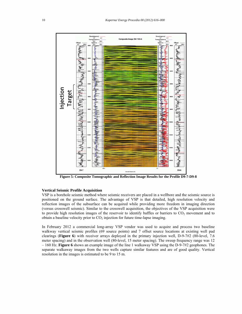
Pulsed Neutron Capture Pulsed neutron capture is a logging method that holds promise for CO2 saturation detection through the use of the thermal neutron capture cross-section application. Because of the large absorption contrast between CO2, which is a very weak neutron absorber (gas or liquid phase), and chlorine, which is a strong neutron absorber, a change in neutron capture due to a buildup of CO2 is readily identifiable, particularly in saline water bearing formations such as the Paluxy Formation at Citronelle. Baseline pulsed neutron capture logs were run on the three new project wells and will be repeated annually during the injection. Injection Surveys Periodic injection surveys (tracer surveys and/or spinner surveys) will be run in the injection well to determine the relative volumes of CO2 going into each perforated interval. Seismic Monitoring Multiple wellbore seismic monitoring methods are being deployed at the Anthropogenic Test including crosswell seismic, long receiver array vertical seismic profiles (VSP) and a semi-permanent limited receiver installed as part of the experimental monitoring effort (see next section) for use in VSP surveys. Unique challenges to the use of seismic monitoring at the Anthropogenic Test include the depth of the injection zone (2,865 m), injection into thin, stacked reservoir sands (6-12 m thick), and the limited CO2 volumes injected. For the above reasons and due to its lower vertical resolution and higher signal to noise ratio the use of surface seismic was eliminated. However, the new wells drilled for the effort and their interwell spacing also lent themselves to the use of borehole seismic methods. Crosswell Seismic Acquisition A baseline integrated crosswell seismic profile acquisition was conducted by as part of the geological characterization and CO2 monitoring effort. Crosswell seismic has the capacity to provide high acoustic frequency data with a high signal to noise ratio. The objectives of the acquisition were to provide high resolution images of the reservoir to assess reservoir heterogeneity and identify baffles or barriers to CO2 movement and to obtain a baseline velocity prior to CO2 injection for future time-lapse imaging. A single crosswell seismic profile was acquired focusing on the injection reservoir. The wells utilized during the project were the primary injection well, D-9-7#2 (used as the source well for the acquisition) and the project monitoring well, D-9-8#2 (used to house the receiver array) (Figure 3). The depth range for the project was approximately 2,487 to 3,200 meters, while the crosswell distance was 257 meters (distance between wellheads). The survey acquired high frequency data (100-1,200 Hz) at 3 meter spacing (source and receiver). Figure 5 shows the composite tomographic (background color) and reflection image results for the profile. The high resolution structural image did not reveal any visible structural barriers or faulting that could affect the movement and the storage of the CO2 along the profile and shows a vertical resolution of +/-3 meters. This profile acquisition will be repeated once post-injection to attempt high-resolution imaging of the CO2 plume. The repeat acquisition should have the capability to detect velocity changes of less than 2%.
10 Koperna/ Energy Procedia 00 (2012) 616–000
Figure 5: Composite Tomographic and Reflection Image Results for the Profile D9-7-D9-8
Vertical Seismic Profile Acquisition VSP is a borehole seismic method where seismic receivers are placed in a wellbore and the seismic source is positioned on the ground surface. The advantage of VSP is that detailed, high resolution velocity and reflection images of the subsurface can be acquired while providing more freedom in imaging direction (versus crosswell seismic). Similar to the crosswell acquisition, the objectives of the VSP acquisition were to provide high resolution images of the reservoir to identify baffles or barriers to CO2 movement and to obtain a baseline velocity prior to CO2 injection for future time-lapse imaging. In February 2012 a commercial long-array VSP vendor was used to acquire and process two baseline walkway vertical seismic profiles (69 source points) and 7 offset source locations at existing well pad clearings (Figure 6) with receiver arrays deployed in the primary injection well, D-9-7#2 (80-level, 7.6 meter spacing) and in the observation well (80-level, 15 meter spacing). The sweep frequency range was 12 – 160 Hz. Figure 6 shows an example image of the line 1 walkaway VSP using the D-9-7#2 geophones. The separate walkaway images from the two wells capture similar features and are of good quality. Vertical resolution in the images is estimated to be 9 to 15 m.
Injection
Target
Injection
Target

Koperna et al/ Energy Procedia 00 (2011) 616–000 11
Figure 6: Baseline D-9-7#2 Line 1 Walkaway VSP
Experimental Monitoring Experimental monitoring methods to advance the science of saline reservoir CO2 monitoring have been opportunistically added to the Anthropogenic Tests MVA program. These include a comparison of deep groundwater sampling methodologies (a collaboration with the United States Geological Survey) and the deployment of an Integrated Modular Borehole Monitoring (MBM) System (a collaboration between SECARB, the CO2 Capture Project and Lawrence Berkeley National Laboratory). Comparison of Groundwater Sampling Methodologies Groundwater sampling and analysis is an integral component of evaluating formation geochemistry and detecting CO2 leakage. Typically groundwater samples collected from depth are brought to the land surface where the samples undergo significant de-pressurization. Dissolved gases can come out of solution potentially driving the groundwater chemistry to a state of disequilibrium. Subsequent analyses of the groundwater samples could result in measurement of dissolved groundwater constituents (gases, organics and inorganics) that are not representative of in-situ conditions. This effort deployed different sampling technologies (e.g., u-tube, gas-lift, pumping and wireline sampling), in the D-9-8#2 monitoring well, to evaluate the impact that sampling methodology has on groundwater quality results. A technical comparison of the analytical results and the economics of each sampling method will be evaluated during the study. The results of this experimental project will be used to inform stakeholders and regulators of the best available sampling methodologies. Modular Borehole Monitoring System The project team installed an innovative tubing deployed modular borehole monitoring (MBM) system designed at Lawrence Berkeley National Laboratory and supported by CO2 Capture Project (CCP) as a field trial project. The MBM was designed with the aim of deploying a robust flexible monitoring package that maximizes the data collected in a single well monitoring system while minimizing installation risk. This system includes a U-tube reservoir fluid sampler, heat-pulse cable with fiber-optic distributed temperature sensor (DTS), a geophone array for borehole seismic acquisition and discrete down hole pressure/temperature sensors at the level of the storage reservoir. The MBM system was installed in March
Injection Zone

12 Koperna/ Energy Procedia 00 (2012) 616–000
2012 and all of the components were tested and baseline measurements were performed prior to the onset of CO2 injection. This baseline monitoring effort included the acquisition and characterization of reservoir fluid samples, testing of the heat-pulse/DTS system, a continuous record of reservoir pressure and the acquisition of baseline vertical seismic profiles using the borehole geophone array. Summary The Anthropogenic Test is now operating at full capacity, receiving 500 metric tonnes per day or more of CO2 from the Plant Barry capture facility. Baseline surface, subsurface and CO2 stream monitoring was completed prior to injection providing a comparative background for injection and post-injection monitoring efforts. Injection is expected to continue late into 2012 and then shut down temporarily due to seasonal outage of the coal-fired unit which supplies CO2 to the capture facility. Capture and injection operations are expected to restart in early 2013. Injection well tubing pressure and reservoir pressure are being continuously recorded. Time-lapse measurements are currently being scheduled for late 2012 including reservoir fluid sampling events, injection surveys and well logging. Experimental monitoring activities, including those using the MBM’s components, will take place in early 2013. Injection phase monitoring data will be used to update and calibrate the baseline injection simulation. The new simulation will be used to update the project’s area of review, an annual UIC permit requirement, which is based on an estimate of the CO2 plume’s migration and the injection’s pressure field. CO2 injection operations will likely continue in 2014 and post-injection monitoring will take place through 2017. Acknowledgements Denbury Onshore, LLC, and operator of the Citronelle Field, is gratefully acknowledged for their essential contribution to this CO2 storage demonstration, particularly Mr. West Richardson, Mr. Gary Dittmar and Mr. Tommy Miller. Further, the project team also acknowledges the cost share and technical expertise provided by the Electric Power Research Institute and Southern Company, without which, this project would still only be a conceptualization. Finally, the project team would like to recognize Ms. Shawna Cyphers for her continued geoscience efforts on the project. Disclaimer This paper is based upon work supported by the Department of Energy National Energy Technology Laboratory under DE-FC26-04NT42590. This report was prepared as an account of work sponsored by an agency of the United States Government. Neither the United States Government nor any agency thereof, nor any of their employees, makes any warranty, express or implied, or assumes any legal liability or responsibility for the accuracy, completeness, or usefulness of any information, apparatus, product, or process disclosed, or represents that its use would not infringe privately owned rights. Reference herein to any specific commercial product, process, or service by trade name, trademark, manufacturer, or otherwise does not necessarily constitute or imply its endorsement, recommendation, or favoring by the United States Government or any agency thereof. The views and opinions of authors expressed herein do not necessarily state or reflect those of the United States Government or any agency thereof.

Koperna et al/ Energy Procedia 00 (2011) 616–000 13
References [1.] Koperna, G. J., Jr., Kuuskraa, V., Riestenberg, D., Rhudy, R., Trautz, R., Hill, J., and
Esposito, R.; “The SECARB Anthropogenic Test: A U.S. Integrated CO2 Capture, Transportation and Storage Test”, International Journal of Clean Coal and Energy, 1, pp. 13-26, 2012.
[2.] Nunez-Lopez, V. and Hovorka, S. D.; “Subsurface Monitoring of Large-Scale CO2 Injection at SECARB’s Phase-III Cranfield Site”, CMTC 151504, presented at the 2012 Carbon Management Technology Conference, Orlando, Florida, USA, February 7-9, 2012.
[3.] Esposito, R., Rhudy, R., Trautz, R., Koperna, G., and Hill, J.; “Integrating Carbon Capture with Transportation and Storage”, Energy Procedia, 4, 5512 – 5519, 2011.
[4.] Esposito, R., Harvick, C., Mooneyham, D., Trautz, R., and Hill, G.; “Integration of Pipeline Operations Sources with CO2 Captured at a Coal-fired Power Plant and Injected for Geologic Storage: SECARB Phase III CCS Demonstration”, GHGT-11 Proceedings, 2012.
[5.] Esposito R. A., Pashin J. C., Walsh, P. M.; “Citronelle Dome: A Giant Opportunity for Multi-Zone Carbon Storage and Enhanced Oil Recovery in the Mississippi Interior Salt Basin of Alabama”, Environmental Geosciences, v 15, p. 53-62, 2008.
[6.] Mancini, E. A. and Puckett, T. M.; “Jurassic and Cretaceous Transgressive-Regressive Cycles, Northern Gulf Of Mexico, U.S.A.”, Stratigraphy, v. 2, p. 30-47, 2005.
[7.] Petrusak, R., Riestenberg, D., and Cyphers, S.; “Core and Log Analyses for Reservoir Characterization of the Paluxy Formation at Citronelle Dome for the Southeast Regional Carbon Sequestration (SECARB) Partnership Phase III Anthropogenic Test”, proceedings of the 10th Annual Conference on Carbon Capture and Sequestration, May, 2011.
[8.] Riestenberg, D. E., Koperna, G. J., Kuuskraa, V. A., and Esposito, R. A.; “Using Reservoir Architecture to Maximize CO2 Storage Capacity,” SPE 118939, presented at the 2008 AAPG-SPE Eastern Regional Meeting, Pittsburgh, PA., October 11-15, 2008.
[9.] Environmental Protection Agency (EPA) Office of Water 4606, EPA 816-R-02-025. [10.] McCallum, S. D., Phelps, T. J., Riestenberg, D. E., Friefeld, B. M., and Trautz, R. C.;
“Interpretation of Per Fluorocarbon Tracer Data Collected During the Frio Carbon Dioxide Sequestration Test”, presented at the American Geophysical Union Fall Meeting, San Francisco, California, paper GC13A-1214. GCCC Digital Publication Series #05-03f, pp. 1-2, December 5–9, 2005.
[11.] Wells, A.W., Diehl, J. R., Bromhal, G., Strazisar, B. R., Wilson, T. H., and White, C. M.; “The Use of Tracers to Assess Leakage from the Sequestration of CO2 in a Depleted Oil Reservoir, New Mexico, USA”, Applied Geochemistry 22: 996-1016, 2007.