the s-90 go-kart optimal design report documents... · the s-90 go-kart optimal design report by...
TRANSCRIPT

The S-90 Go-Kart
Optimal Design Report
By
James Paolino, Alexander Jadczak, Eric Leknes, and Tarek Tantawy
Sean Stenglein. NSF Projects.
Ashford, CT. 860-429-1059
1. Optimal Design
1.1 Introduction
This project is intended to design and create a go-kart for a child with severe cerebral palsy. The
client is a ten year old male who is very smart and enjoys all things related to motor vehicles and driving.
His condition makes it nearly impossible for him to operate a typical go-kart, however. The client has no
reliable use of his arms or legs at this time. He has been working to develop enough motor control in his
arms to allow him to use a power wheelchair with joystick control. The client can use a head switch with
great reliability and this is an important factor in the design of this go-kart.
In addition to a lack of reliable motor control the client also needs to be positioned correctly
both for comfort, and to optimize the motor control he does possess. He needs to be secured tightly in
his seat at the waist. This is to ensure that his waist is constantly at a 90⁰ angle, which helps his
movement. The controls must also be setup in such a way that the client’s thumbs are pointing upwards.
This is both to help train his muscles to maintain that position and for comfort. The most important part
of this go-kart is to maximize the client’s safety and fun while using it.
The go-kart for this project will be built from the ground up to maximize the efficient use of
space, and to ensure that the needs of the client are met. The frame will consist of a steel open roll cage
design with independent front suspension and semi-independent rear suspension. A 10 horsepower gas
motor will provide power for the drive, and also run a 7 amp alternator. A gas motor will be used both
to provide adequate power, and for the sounds and attitude it brings to the vehicle. To accommodate
the client’s lack of physical ability all of the systems on the go-kart will be actuated using electric motors.
The electric motors will interface to the mechanical systems to control them without the operator
having to apply force directly. This will allow the client to control the go-kart with minimal physical
input.
The power for all of the electrical components essential to the go-kart will come from a deep
cycle car battery. This battery will in turn be charged by the alternator to ensure that there is always
electrical power being supplied to the system. The battery will supply the electric motors and the
electronic control components. These control components are necessary to take small make use of the
user’s inputs to the system and translate them into something that can actually drive the go-kart.
Three possible methods of control will be available on a user-selectable basis. The main method
of control will be a joystick that controls steering, throttle, and braking using a two axis system. This
method is similar to the way the client’s power wheelchair is controlled, and with practice the hope is
that the client will be able to learn this system of control. To allow the client to use the go-kart
immediately the second control system is based on remote control. A radio controller designed for
model aircraft will be controlled by a guardian with similar controls to the joystick. A radio receiver on
the go-kart will take the transmitted signal and feed it to the microprocessor. The final method of

control will be a steering wheel and pedals that will allow the vehicle to be operated like a normal car or
go-kart. These inputs will be connected to the microprocessor instead of mechanically attached. By
running all of the control systems through the same microprocessor system switching between the
methods of control is simplified. This method also isolates each system from the motors, ensuring that
only one control method can be in use at any given time.
In addition to the custom control methods this go-kart will have a number of other features
tailored directly to meet the client’s needs. The seat is the most important of these features. The
Tumble Forms 2 Carrie seating system is designed to keep the client bent 90⁰ at the waist at all times.
This is essential for allowing the client to maximize his limited movement while driving the go-kart. The
Carrie seat is expensive, so a mount will be made to allow the client’s current Carrie seat to easily
attached and removed from the go-kart. This will allow the client to have the proper seating
arrangements without breaking the budget of the project.
The client’s most reliable form of physical control is his use of a head switch. For safety reasons,
a head switch will be used as a kill switch for the go-kart. This safety feature will allow the client to stop
the go-kart at any time he feels unsafe or out of control. It is also important for the client’s thumbs to be
pointed upwards while he is performing most activities. The meet this specification Velcro on the
steering wheel and the joystick will be coupled with special gloves for the client to wear. The Velcro will
hold the client’s hands in the correct position regardless of the selected control method.
1.2 Subunits
The complete go-kart described above is made up of a number of smaller systems that come
together to make everything work. Each of these subunits has to be carefully designed so that it not only
accomplishes its task, but also integrates into the larger system. The following section details the design
of each of these subunits, and describes where they fit in the complete design.
Software Control Architecture
The go-kart will rely heavily on software control to allow it to function with minimal physical
inputs from the operator. Embedded software takes away the need for complex analog circuits that
would otherwise make up a control system like this. The software for the go-kart has two main
purposes: to provide control over all of the systems necessary to operate the go-kart, and to recognize
when the go-kart is not functioning properly and to shut it down safely. To accomplish these two tasks
the software will be comprised of two infinite loops. The primary loop will service all of the normal
routines that must be controlled, and check to make sure everything is operating properly. The
emergency loop will be activated by the primary loop and will function to safely shut down the go-kart
and keep it shut down. The basics of the overall software design are discussed in this section, each
major component is discussed in detail in its corresponding section.
Microcontroller Hardware
The hardware that will be responsible for running the software routines is the Microchip
PIC16F877. This is a 40-pin version of Microchip’s mid-level 8-bit microcontroller. This microcontroller is
ideal because it combines versatility with simplicity. The PIC16F877 has a number of peripherals and
modules embedded in its design that can be easily accessed and put to use through relatively simple
coding. The PIC includes an on-board analog to digital (A/D) converter, two pulse width modulation
modules, and a number of other useful features. The 40 pins combine to have 35 input/output ports, 8
of which can take an analog input and route it through the A/D converter. Due to the constraints of only
two PWM modules, however, the go-kart will make use of two PICs running in parallel to one another.
Programming Language
The PIC16 series microcontrollers are designed to operate based on a 35 function instruction
set. Each instruction corresponds to one or two machine cycles of the microcontroller. Programming
language that makes use of only instruction set commands called assembly language. Assembly is
efficient to run, but tedious to write. For this application embedded C code will be used for writing
microcontroller software. Embedded C essentially takes the C code programming language and converts
it into the equivalent assembly instruction set. This set is then loaded onto the chip and run
continuously. C code is more intuitive to use than assembly and there are fewer chances of major
software errors that could otherwise prove to be dangerous.
Steering
Steering Mechanics
The steering system of the vehicle is designed to be able to withstand the large forces generated
from the steering gearmotor. The gearmotor itself will be mounted to a plate that is attached to the
front suspension supports. The gearmotor will have a 2:1 increase in gear ratio so that it will drive the
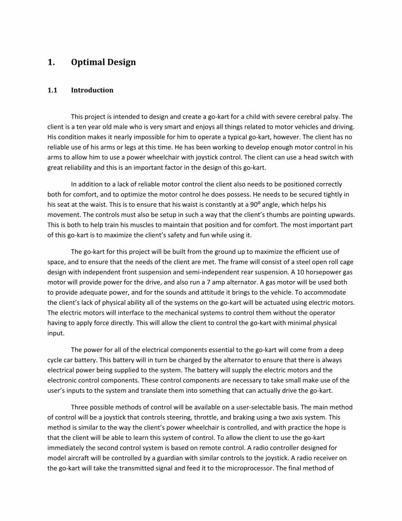
rack and pinion at 180rpm. The gear on the gearmotor output will be a 48tooth spur gear, part number
6325K21 from mcmastercarr.com and the gear on the rack and pinion will be a 24 tooth spur gear, part
number 6325K16 from mcmastercarr.com. The assembly will go together as shown in Fig. 1.
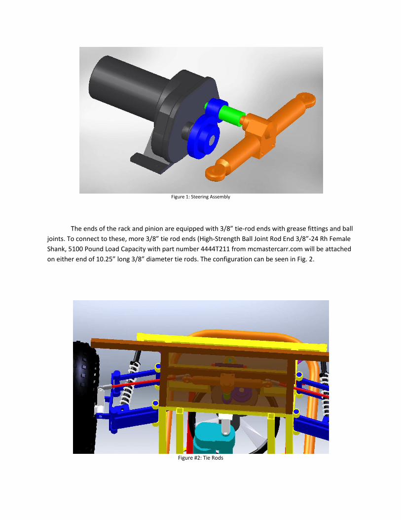
Figure 1: Steering Assembly
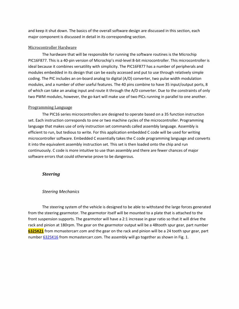
The ends of the rack and pinion are equipped with 3/8” tie-rod ends with grease fittings and ball
joints. To connect to these, more 3/8” tie rod ends (High-Strength Ball Joint Rod End 3/8”-24 Rh Female
Shank, 5100 Pound Load Capacity with part number 4444T211 from mcmastercarr.com will be attached
on either end of 10.25” long 3/8” diameter tie rods. The configuration can be seen in Fig. 2.
Figure #2: Tie Rods

The tie rod ends will then connect to the front wheel spindles via the extended lever arms with 3/8”
holes as shown above.
The steering wheel assembly will be made to be adjustable in terms of height and depth. The
depth adjustment will be set by a knob put into a tapped hole in a 7/8” OD, 5/8” ID sheath. A 5/8” rod
going through two sets of bearings will be inserted into the sheath on one end and left loose so that the
knob pressure can lock it in position while another 5/8” piece of rod that is attached to the steering
wheel mount will be inserted into the other end of the sheath. The piece of rod going through the
bearings will have its end lathed down to ¼” for a length of about 1.5” so that a timing pulley can be
placed on the end of it. Another timing pulley will be fixed to a shaft of a potentiometer and will be
mounted to the extended plate that the bearings are mounted to. The area between the bearings will
house an assembly consisting of two springs on either side of the steering column, a section of metal
cable that has been wrapped around the steering column, and a tack of weld holding the center of the
metal cable to the column. The purpose of this apparatus is to center the wheel automatically to give
the driver a sense of natural wheel return as well as automatically calibrating the steering wheel to the
forward position on startup. The general setup is shown in Fig. 3.
The steering assembly will be able to tilt up and down based on the pivot/mounting point at the
base of the assembly, and a pin that will slide through the metal tube mounted under the plate shown.
The pin will go through two support arms not shown that will be mounted to the front suspension
support bar at simple pivot points. The adjustment will be incremental, as there will be set holes drilled
in the support arms that the pin can go through to lock the height of the steering assembly.
Figure #3: Steering Wheel Assembly
Steering Control
The steering control is one of the most important subsystems on the entire vehicle, and i
one of the most novel. In order for the steering on this go
to move the wheels in a way comparable to how a fully capable person with a steering wheel can. A
number of components go into this syst
the steering control are: the rack and pinion with linkage, a
transducer, an IFI Thor 883 speed controller,
components will be described in detail below.
Dayton 1L469 Gearmotor
The Dayton model number 1L469 gear motor will be used as the steering motor in the go
The motor is geared in such a way to produce 50 inch pounds of torque and rotate a
operating voltage of the motor is 12 volts with a full load current of 9.0amps. The 12 volt input for the
motor is ideal for this particular situation as it is the same voltage as the battery. An IFI Thor 883 speed
controller will be supplying the gearmotor with the forward and reverse currents allowing the motor to
turn clockwise or counterclockwise as needed. The gear motor will only be drawing power when the
wheels need to be turned and not when the go
7 amp alternator will be able to recharge the battery. A gear on the shaft of the motor will interface
with the gear on the rack and pinion for the steering of the go
feed back to the logic unit, determining the position of the wheels, and in turn determining whether or
not the gearmotor needs to be activated and rotated. Rotating at 90 RPM will move the rack and pinion
back and forth from one extreme to the other in a short period of time,
the direction of the go-kart. For the gear ratios selected, it will take one second for the gearmotor to
cause the rack and pinion to travel from one extreme to the other. The gear motor will be bolted to a
mounting plate which will in turn be welded to the chassis of the go
The steering control is one of the most important subsystems on the entire vehicle, and i
one of the most novel. In order for the steering on this go-kart to be useful to the client it has to be able
to move the wheels in a way comparable to how a fully capable person with a steering wheel can. A
number of components go into this system which allows it to accomplish this task. The components of
the steering control are: the rack and pinion with linkage, a Dayton 1L469 gearmotor, a
speed controller, software controls, and the input control. Each
components will be described in detail below.
The Dayton model number 1L469 gear motor will be used as the steering motor in the go
The motor is geared in such a way to produce 50 inch pounds of torque and rotate at 90 RPM. The
operating voltage of the motor is 12 volts with a full load current of 9.0amps. The 12 volt input for the
motor is ideal for this particular situation as it is the same voltage as the battery. An IFI Thor 883 speed
ying the gearmotor with the forward and reverse currents allowing the motor to
turn clockwise or counterclockwise as needed. The gear motor will only be drawing power when the
wheels need to be turned and not when the go-kart is maintaining a particular wheel position, thus the
7 amp alternator will be able to recharge the battery. A gear on the shaft of the motor will interface
with the gear on the rack and pinion for the steering of the go-kart. A linear position encoder will give
unit, determining the position of the wheels, and in turn determining whether or
not the gearmotor needs to be activated and rotated. Rotating at 90 RPM will move the rack and pinion
back and forth from one extreme to the other in a short period of time, allowing for good control over
kart. For the gear ratios selected, it will take one second for the gearmotor to
cause the rack and pinion to travel from one extreme to the other. The gear motor will be bolted to a
which will in turn be welded to the chassis of the go-kart.
Figure #4: Dayton Gearmotor
The steering control is one of the most important subsystems on the entire vehicle, and it is also
kart to be useful to the client it has to be able
to move the wheels in a way comparable to how a fully capable person with a steering wheel can. A
em which allows it to accomplish this task. The components of
gearmotor, an LWG position
software controls, and the input control. Each of these
The Dayton model number 1L469 gear motor will be used as the steering motor in the go-kart.
t 90 RPM. The
operating voltage of the motor is 12 volts with a full load current of 9.0amps. The 12 volt input for the
motor is ideal for this particular situation as it is the same voltage as the battery. An IFI Thor 883 speed
ying the gearmotor with the forward and reverse currents allowing the motor to
turn clockwise or counterclockwise as needed. The gear motor will only be drawing power when the
heel position, thus the
7 amp alternator will be able to recharge the battery. A gear on the shaft of the motor will interface
kart. A linear position encoder will give
unit, determining the position of the wheels, and in turn determining whether or
not the gearmotor needs to be activated and rotated. Rotating at 90 RPM will move the rack and pinion
allowing for good control over
kart. For the gear ratios selected, it will take one second for the gearmotor to
cause the rack and pinion to travel from one extreme to the other. The gear motor will be bolted to a

Position Transducer
The rack and pinion is not mechanically connected to any of the user interfaces for the steering
control system. For this reason it is important that there is another way of tracking the position of the
rack and pinion, and ultimately the wheels themselves. This is done using a NovoTechnik LWG Series
position transducer as shown in Fig. 5. This transducer has potentiometric properties based on the
position of the shaft in its sleeve. The theory behind this mode of operation is that as the shaft moves it
changes the internal resistance of the device. By applying a reference voltage to the device a voltage
divider is created. The output voltage of the device then becomes dependent on the position of the
shaft, and the corresponding resistance.
The LWG position transducer will be attached parallel to the rack and pinion. As the gearmotor
moves the rack and pinion the linear motion will also be transferred to the position transducer. With
this setup the output voltage of the position transducer becomes a measure of absolute position of the
rack and pinion and ultimately a measure of exactly which way the wheels are turned. This output
voltage is connected directly to one of the input ports of the microcontroller for processing.
Control Methods
The three selectable methods of control are the main user interfaces for the go-kart. Each of
them is designed to carry out the same function, but the reason for each method is unique. The joystick
is intended to be the primary mode of control for the go-kart. It will likely take a lot of practice for the
client to learn how to use, but it provides him with total control of the vehicle for himself. The radio
control method is designed to allow the client to use the go-kart right away. His parents will be able to
grasp the controls quickly, and this method requires little to no input from the client himself. The
steering wheel with pedals method of control is there for two reasons. There is a hope the someday the
client will be able to master his condition well enough to drive normally. It is also there to allow other
operators a chance to drive the go-kart normally.
Figure #5: NovoTechnik Linear Position Transducer

Joystick
The joystick control is considered the primary control because it is the most direct form. Many
of the elements of this control system are used in the other two systems also.
Controls Inc., M215-28, which has two axes of m
will not be used on the go-kart. When the rocker switch goes unused the joystick has four useful leads.
Two correspond to the positive and negative supply voltages, and the other two correspond to the
y axes of control. The M215-28 works like two potentiometers. Each axis outputs a voltage based on the
position of the joystick handle. These values are taken separately on the two distinct output leads. Full
positive deflection causes an output of
20% of the supply voltage. When the handle is resting in the middle both outputs present 50% of the
supply voltage. These output voltages are connected directly to an input port of the microco
processing.
The M215-28 joystick will be used to control the steering, throttle, and braking when the go
is in joystick control mode. The x-axis will control the steering, and the y
throttle and the brakes. The direction of the wheels will follow the position of the joystick on the x
and the entire axis will be used for this mode of control. The y
splitting the axis down the middle. As the joystick handle is pushed
will be progressively opened. Likewise, as the handle is pulled back down the y
incrementally engaged. When the handle rests in the middle of the y
brake disengaged.
The joystick control is considered the primary control because it is the most direct form. Many
of the elements of this control system are used in the other two systems also. The joystick is a P
28, which has two axes of motion and a rocker switch at the top. The rocker switch
kart. When the rocker switch goes unused the joystick has four useful leads.
Two correspond to the positive and negative supply voltages, and the other two correspond to the
28 works like two potentiometers. Each axis outputs a voltage based on the
position of the joystick handle. These values are taken separately on the two distinct output leads. Full
positive deflection causes an output of 80% of the supply voltage and full negative deflection outputs
When the handle is resting in the middle both outputs present 50% of the
These output voltages are connected directly to an input port of the microco
28 joystick will be used to control the steering, throttle, and braking when the go
axis will control the steering, and the y-axis will control both the
direction of the wheels will follow the position of the joystick on the x
and the entire axis will be used for this mode of control. The y-axis will control throttle and braking by
splitting the axis down the middle. As the joystick handle is pushed forward up the y-axis the throttle
will be progressively opened. Likewise, as the handle is pulled back down the y-axis the brake will be
incrementally engaged. When the handle rests in the middle of the y-axis the engine will idle with the
Figure #6: M215-28 Joystick
The joystick control is considered the primary control because it is the most direct form. Many
The joystick is a P-Q
otion and a rocker switch at the top. The rocker switch
kart. When the rocker switch goes unused the joystick has four useful leads.
Two correspond to the positive and negative supply voltages, and the other two correspond to the x and
28 works like two potentiometers. Each axis outputs a voltage based on the
position of the joystick handle. These values are taken separately on the two distinct output leads. Full
80% of the supply voltage and full negative deflection outputs
When the handle is resting in the middle both outputs present 50% of the
These output voltages are connected directly to an input port of the microcontroller for
28 joystick will be used to control the steering, throttle, and braking when the go-kart
axis will control both the
direction of the wheels will follow the position of the joystick on the x-axis,
axis will control throttle and braking by
axis the throttle
axis the brake will be
axis the engine will idle with the

Radio Control
The radio control is the most complex method of control from an electronics standpoint. The
radio control will be implemented using a Futaba Skysport 4YF controlled coupled with a Futaba FP-
R127DF receiver. This controller-receiver combination is designed for use with model airplanes and
offers a 650 foot range. The controller makes use of two twin axis joysticks for control. Each axis on the
controller outputs to a different channel on the receiver, giving four possible outputs that can be used
for controlling the go-kart.
The signal that is output from the receiver is in the form of pulse width modulation (PWM);
because it is designed to directly drive the small servo motors in model airplanes. The pulse width is
changed based on the position of the joystick axis on the controller. While PWM is a convenient signal
form to drive a servo motor directly, it is difficult to make use of as a microcontroller input. To make use
of the signal coming from the receiver the PWM must be converted into an analog voltage before being
routed to the microcontroller.
Figure #7: RC Smoothing Circuit Diagram and Results

The easiest way to make this digital to analog conversion is to use a simple RC circuit to smooth
the pulses and give an average DC value. The smoothing effect of the capacitor in the RC circuit creates
an averaging effect on the pulses, and creates an analog output proportional to the duty cycle of the
PWM. As the duty cycle increases the DC voltage increases giving a controllable analog signal that can be
taken by the microcontroller. Once the analog signal arrives at the microcontroller it can be processed in
the same manner as the joystick voltage signal. Fig. 7 above shows the effectiveness of this method. The
circuit in the diagram was run using a 2.5% duty cycle and a 7.5% duty cycle. There is clear change in the
output voltage that can be used for A/D conversion.
Steering Wheel and Pedals
The steering wheel with pedals is the third mode of control for the go-kart. It works off of nearly
identical principles as the joystick. The steering wheel will be mechanically attached to a potentiometer
via a belt. The turning of the wheel will subsequently turn the potentiometer and change the output
voltage with respect to the supply. This voltage will then be sent directly to the microcontroller. A spring
mechanism will center the steering wheel when no force is being applied to it. This is intended to give
the operator the feel of a normal vehicle where the wheels work to right themselves automatically.
The pedals will work in the same way as the steering wheel, except they will be directly linked to
potentiometers. There will be separate potentiometers to control the throttle and braking, as they will
take inputs from two separate pedals. Both signals from the potentiometers will be connected directly
to inputs on the microcontroller. Each of the pedals will also be attached to a spring to bring them back
to their original position. This is important to ensure that neither pedal remains in the active position
when the operator does not intend for them to be there.
Steering Software Control
The software control for steering is responsible for taking information from two main inputs and
using the gathered information to update a single output. The inputs for the steering control come from
the LGW position transducer and the steering output from the selected control method. Both of these
inputs are of the same form when they arrive as signals at the microcontroller. They are both analog DC
voltages, and their magnitude is based on the mechanical positions at their respective origins. Each
signal must go through an analog to digital conversion (ADC) process in within the microcontroller to be
useful for digital analysis. The ADC process is carried out by a routine in the software that utilizes a 10-
bit converter that is on board the PIC16F877 microcontroller. The conversion process compares the
input voltage level to a known reference voltage level and assigned a number 0-1023 based on the
relationship between the two levels. This number is stored to a location on the chip and can be used for
comparisons. The ADC routine written in embedded C code is shown below.
void ReadADC(){
unsigned char wheel1, posit1;
ADCON1 = 0x49; //set for left justified
if(ContMode == 0)
{
ADCON0 = 0x09; // Enable ADC, Fosc/2, for AN1
//ADCON0 = 0x29; // Enable ADC, Fosc/2, for AN5
}
else if(ContMode == 1)
{
ADCON0 = 0x01; // Enable ADC, Fosc/2, for AN0
//ADCON0 = 0x29; // Enable ADC, Fosc/2, for AN5
}
else if(ContMode ==2)
{
PORTD = 0xFF;
return;
}
ADIE = 0; // Masking the interrupt
ADIF = 0; // Resetting the ADC interrupt bit
ADRESL = 0; // Resetting the ADRES value registers
ADRESH = 0;
ADGO = 1; // Staring the ADC process
while(!ADIF) continue; // Wait for conversion complete
wheel1 = ADRESH; //Store position of joystick/RC/wheel
}
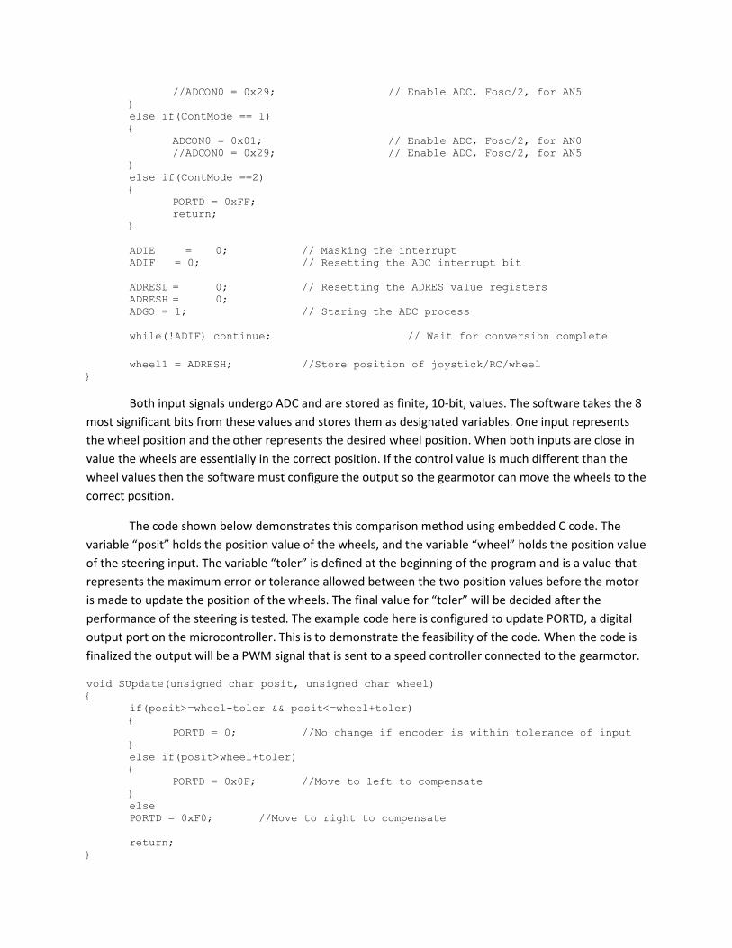
Both input signals undergo ADC and are stored as finite, 10-bit, values. The software takes the 8
most significant bits from these values and stores them as designated variables. One input represents
the wheel position and the other represents the desired wheel position. When both inputs are close in
value the wheels are essentially in the correct position. If the control value is much different than the
wheel values then the software must configure the output so the gearmotor can move the wheels to the
correct position.
The code shown below demonstrates this comparison method using embedded C code. The
variable “posit” holds the position value of the wheels, and the variable “wheel” holds the position value
of the steering input. The variable “toler” is defined at the beginning of the program and is a value that
represents the maximum error or tolerance allowed between the two position values before the motor
is made to update the position of the wheels. The final value for “toler” will be decided after the
performance of the steering is tested. The example code here is configured to update PORTD, a digital
output port on the microcontroller. This is to demonstrate the feasibility of the code. When the code is
finalized the output will be a PWM signal that is sent to a speed controller connected to the gearmotor.
void SUpdate(unsigned char posit, unsigned char wheel)
{
if(posit>=wheel-toler && posit<=wheel+toler)
{
PORTD = 0; //No change if encoder is within tolerance of input
}
else if(posit>wheel+toler)
{
PORTD = 0x0F; //Move to left to compensate
}
else
PORTD = 0xF0; //Move to right to compensate
return;
}

Speed Controller
The gearmotor that powers the steering for the go-kart will be directly regulated by an IFI Thor
883 speed controller. Speed controllers take an input signal and modulate the direction and level of
current that a motor receives. This in turn controls the direction and speed of the motor. The Thor 883
takes a PWM signal, which will come from the output of the microcontroller, and uses the encoded
information to drive the motor. For the purposes of the go-kart the speed controller will be used only to
control the forward and reverse motion of the motor. The 120A continuous current rating for the Thor
883 makes it ideal for the application with the Dayton 1L469 gearmotor, because there is little to no
chance of the motor drawing enough current to blow the speed controller.
Drive Train
The drive train system of the go-kart is designed to be both robust and adjustable. It consists of
an engine mounting plate, a gearbox mounting plate, and the rear axle. The engine mounting plate will
be welded to the chassis at a pre-determined position so that the exhaust from the muffler does not
expel directly onto any components and so that the engine has enough clearance from the rear
suspension. The horizontal positioning of the gearbox mounting plate will be determined by the position
of the Comet 500 series torque convertor setup. The end of the gearbox will have an extra support
bearing that will be mounted to the rear chassis on a slotted piece of metal. The gearbox mounting plate
itself will be adjustable so that the tension in both the torque convertor belt and the drive chain can be
adjusted by turning a 5/8” lead screw. This assembly can be seen in Fig. 8 and Fig. 9. The rear area
where the engine mounting plate will be welded to is shown in Fig. 10.
Figure #8: Gearbox Mount Assembly

Figure #9: Gearbox Mount Assembly (Under)
Figure #10: Rear Chassis (Full)

The driven large sprocket on the rear axle has been tested under a high simulated load, as well
as the axle itself. The included stress analysis shows that they can withstand the forces generated by the
10HP Tecumseh engine under maximum loading conditions with an 800lb assumed vehicle/passenger
weight. Full stress analysis can be found in Appendix A. Both the gearbox and torque convertor are
rated to handle up to 16hp 4-stroke engines. The torque convertor clutch is designed to engage at
2100rpm, meaning that the engine should never stall upon engagement due to the fact that at 2100rpm
it is high up in its power curve. This will provide good initial acceleration of the vehicle, allowing for a
thrilling ride and powerful cornering in off-road conditions.
Engine
The engine selected for this vehicle is the Tecumseh Formula Horizontal Engine with Electric
Start — 10 HP, 1in. x 2 7/8in. Shaft, Model# HM100-168416T. The reason for this engine’s selection is
that it comes with a muffler, a gas tank, a kill switch, a 7 amp alternator, an electric starter and
emergency pull-start option, as well as having 10hp and a 1” diameter drive shaft with ¼” keyway which
fits the donated torque convertor clutch. This motor is also designed for off-roading, so the oil sensor
automatic shutoff is set up so that it won’t automatically shut off the engine if it gets jostled in off-road
conditions. The 10hp fits with the hp ranges for the transmissions (8hp-16hp) without being too
powerful since the client does not need to go very fast. Also, the price of the motor compared to similar
motors with similar features is competitive at $539.99. This motor should allow for an exciting ride with
lots of torque to provide good initial acceleration for the client with a max rpm of about 3800.
Torque Convertor
The automatic part of the transmission is a Comet 500 series torque convertor with a low range of
3.34:1 and a high range of .81:1. This will ensure that at low engine rpm the transmission will still have
enough power to accelerate the go kart by providing a reduction of 3.34 which will be augmented Figure
#11: Tecumseh Formula Horizontal Engine

Figure #12: Gearbox and Torque Conve
to the roughly 6:1 gear ratio provided by the fixed axle and gearbox sprockets. The torque convertor is
belt driven and the clutch is centrifugal, so the passenger will be able to easily maneuver the vehicle at
low speeds due to a combination of belt slipp
dynamic transmission is commonly found in snowmobiles, and allows the engine to reach its full power
curve.
Gearbox
The gearbox is made by Comet, and is for go
16 hp. Lightweight, rugged gearbox that allows operator the selection of three positions: forward,
neutral and reverse. Forward ratio is 1:1 and the reverse ratio is 2.7:1. This is to be used with other
comet torque convertors, like the 500 Ser
mounted to its output shaft, which will engage the drive sprocket on the axle. The input shaft will have
the driven clutch of the torque convertor as well as an extra support bearing on the end of the i
shaft. The gearbox’s mounting plate will be adjustable so that the proper belt and chain tensions can be
achieved.
Throttle
A servo motor controlled by the microcontroller will operate the rotary valve controlling the
throttle on engine. Rotation in one direction gives the engine more gas, and rotation in the opposite
Figure #12: Gearbox and Torque Converter
to the roughly 6:1 gear ratio provided by the fixed axle and gearbox sprockets. The torque convertor is
belt driven and the clutch is centrifugal, so the passenger will be able to easily maneuver the vehicle at
low speeds due to a combination of belt slipping and engine loading decreasing the shaft rpm. This
dynamic transmission is commonly found in snowmobiles, and allows the engine to reach its full power
The gearbox is made by Comet, and is for go-karts, utility vehicles and other applica
16 hp. Lightweight, rugged gearbox that allows operator the selection of three positions: forward,
neutral and reverse. Forward ratio is 1:1 and the reverse ratio is 2.7:1. This is to be used with other
comet torque convertors, like the 500 Series mentioned. The gearbox will have a drive sprocket
mounted to its output shaft, which will engage the drive sprocket on the axle. The input shaft will have
the driven clutch of the torque convertor as well as an extra support bearing on the end of the i
shaft. The gearbox’s mounting plate will be adjustable so that the proper belt and chain tensions can be
A servo motor controlled by the microcontroller will operate the rotary valve controlling the
in one direction gives the engine more gas, and rotation in the opposite
to the roughly 6:1 gear ratio provided by the fixed axle and gearbox sprockets. The torque convertor is
belt driven and the clutch is centrifugal, so the passenger will be able to easily maneuver the vehicle at
ing and engine loading decreasing the shaft rpm. This
dynamic transmission is commonly found in snowmobiles, and allows the engine to reach its full power
karts, utility vehicles and other applications up to
16 hp. Lightweight, rugged gearbox that allows operator the selection of three positions: forward,
neutral and reverse. Forward ratio is 1:1 and the reverse ratio is 2.7:1. This is to be used with other
ies mentioned. The gearbox will have a drive sprocket
mounted to its output shaft, which will engage the drive sprocket on the axle. The input shaft will have
the driven clutch of the torque convertor as well as an extra support bearing on the end of the input
shaft. The gearbox’s mounting plate will be adjustable so that the proper belt and chain tensions can be
A servo motor controlled by the microcontroller will operate the rotary valve controlling the
in one direction gives the engine more gas, and rotation in the opposite

direction limits the gas entering the motor. This throttle motion will be controlled by a closed loop
system that will verify the expected position of the servo motor and ensure that the throttle is always in
the correct place.
Input Control
The input for the throttle control system comes from the selected method of overall control.
These methods of control are described above in the Steering Control section of this report. Regardless
of the method of control, the signal that ends up as an input to the microcontroller is an analog voltage
corresponding to the position of the input controller. This analog signal is converted to digital as it
enters the microcontroller and from there the software uses this signal for comparison.
Feedback Potentiometer
The shaft of the servo motor that is attached to the throttle control will also be attached directly
to a potentiometer. This potentiometer will serve to provide feedback data for the position of the servo
motor and ultimately the throttle. As the servo motor turns it will also turn the potentiometer, which
will modify the output voltage going to the microcontroller. This step is not necessary for the function of
the servo motor, but it is useful to confirm that the servo motor is operating correctly. In an important
application like throttle control it is important to be sure that all components are responding properly to
the control system. If the signal from the potentiometer does not correctly correspond to the PWM
signal being sent to the servo motor the software will automatically send the go-kart into the emergency
shutdown routine.
Throttle Servo Motor PWM
The servo motor on the throttle takes a pulse width modulation signal to determine the position
in its rotation that it should jump to. The various positions of the throttle control valve will correspond
to different points in the servo rotation, and the PWM signals corresponding to those points. The
software will take the digitally converted signal from the selected control method and compare the
desired position of the throttle to the actual position of the throttle servo. If the two positions do not
match within a relative tolerance the software will modify the output port to the PWM signal
corresponding to the desired position.
Braking System
The system for braking control is very similar to the system for steering control. It uses a smaller
gearmotor to move the lever to open and close the caliper. The action of the gearmotor is controlled
using a microcontroller and a commercial H-bridge.
Mechanical Braking System
The brake system has been over-built as a safety concern. The 10” disk brake is much larger than
a typical 6” disk brake used on most go-karts. This combined with a high end twist-type caliper system

allows for tremendous forces to be generated on the brake with moderate forces applied to the caliper
lever arm. The lever arm will be actuated by using a high-torque gearmotor that will have a further
improved mechanical advantage before being linked to the caliper lever arm. The increase in mechanical
advantage is possible due to the fact that the brake caliper lever only needs to move ½” for a fully open
to fully closed position, so the gearmotor being used can convert all of its speed in its rotating parts to a
very high pulling force. The general position of the brake and the general location of where the caliper
will be located can be seen in Fig. 13.
AME 218-series gearmotor
The AME 218-series gearmotor will be used to apply a force to the braking mechanism. This
gear motor operates at 12 volts, the same voltage supplied by the batter, rotating at 116 RPM when no
load is applied. With no load on the gearmotor 1.4 amps are drawn and at stall the gearmotor draws
21.3 amps. This gearmotor is able to supply 98 inch pounds of torque. The Simple-H H-bridge will be
supplying the power to this gear motor in the forward and reverse directions. When current is flowing
in the forward direction, this gearmotor will rotate applying a force to the brake lever on the disc brake
assembly. The lever will then in turn press the ceramic pads against the disc brake, slowing the go-kart.
A linear position encoder will be used to determine the position of the brake lever, and in turn will
determine whether or not the gearmotor needs to be turned on and the position of the lever adjusted.
This feedback will keep the motor from applying excessive force to the braking assembly and will keep
the motor from burning out due to extended periods of activation. Sending current through the
gearmotor in the reverse direction will release the brake. The position of the gearmotor will be
constantly monitored whether it is applying a force to the braking mechanism or released.
Figure #13: Rear Base Composite Assembly

Braking Control System
Braking H-Bridge
The commercial H-bridge that will be used to drive the braking gearmotor is the SyRen
Regenerative Motor Driver. This driver takes a PWM signal from the microcontroller and uses it to
switch the direction of the current flowing into the gearmotor. The SyRen is rated for use with 25A
continuous current and can handle current spikes up to 45A. This is much more current than the braking
gearmotor would ever actually draw, which means that the chances of this component failing are small.
The SyRen will control switching between full forward, full reverse and idle. This will correspond to the
opening and closing of the brake calipers, as well as allowing them to hold position.
Braking Position Transducer
The braking motor has no way of tracking its own position, so position will be measured using a
NovoTechnik LWG Linear Position Transducer. The equipment and method for control using this position
transducer is nearly identical to the method used for tracking the steering position. It is important to
have data about the position of the brake calipers to allow for smooth braking. If the braking were to be
done using only limit switches the only braking options would be full brakes or no brakes. The position
transducer allows enough feedback from the brake mechanism to the microcontroller to incrementally
increase braking power using the software.
Braking Control Software
The software controlling the braking system takes two inputs and compares them to modify a
single PWM output. The two inputs are the signal from the selected control method, and the signal from
the linear position transducer attached to the braking gearmotor. The input from the user controls will
only utilize the bottom half of the y-axis (except for the pedal control method) and the software will
default to no brakes when the go-kart is accelerating. The braking will be setup to run to a specified
number of positions based on the intensity of the stopping needed. Each position of the brake will be a
case and have constraints. If the position transducer is not in the correct position based on the current
selected case the software will send the appropriate PWM to the H-bridge to correct the position of the
brakes.
Gearbox Control
The go-kart will have a transmission that can switch the drive from the engine between forward
and reverse. This will be accomplished by attaching a linear actuator to the selector arm of the
transmission. The linear actuator will be controlled by the software and a custom designed H-bridge.
Gearbox H-Bridge
The transmission H-bridge will be designed using a very simple h-bridge concept. It uses two
mechanical relays and two limit switches to route current between the two poles of the linear actuator.

The diagram below shows the design of the h
the microcontroller it opens and allows current to flow into the positive terminal from the high side of
the bridge. When the linear actuator reaches the limit
negative terminal of the actuator. The linear actuator will stay in place until the microcontroller
activates the other relay at which point the actuator will move off of the first limit switch and move until
it hits the other limit switch.
Gearbox Control
The software control for the transmission will be a very simple design. A switch on the side of
the go-kart will be able to be set for either forward or reverse. This switch will send a digital signal to the
correct input pin on the microcontroller. The software will compare the digital signal to the last one it
received and if they are different it will activate the output to switch which relay is active at that point.
This method is a simple, yet effective wa
handle.
Motion System 9234c120 linear actuator
The Motion System Corp model 9234C120
lever on the gearbox of the go-kart. This actuator is able to provide enough force and has a long enough
stroke to push the gear lever from the forward to reverse posi
consequently the same voltage as the battery for the go
suitable for the task of changing gears in the gearbox. External limit switches will be placed such that
the current flowing to the actuator will be halted once the gear lever is in its proper position. This will
Figure #14
gram below shows the design of the h-bridge. When the first relay is activated by a signal from
the microcontroller it opens and allows current to flow into the positive terminal from the high side of
the bridge. When the linear actuator reaches the limit switch it cuts off the current flow from the
negative terminal of the actuator. The linear actuator will stay in place until the microcontroller
activates the other relay at which point the actuator will move off of the first limit switch and move until
The software control for the transmission will be a very simple design. A switch on the side of
kart will be able to be set for either forward or reverse. This switch will send a digital signal to the
orrect input pin on the microcontroller. The software will compare the digital signal to the last one it
received and if they are different it will activate the output to switch which relay is active at that point.
This method is a simple, yet effective way to switch gears without heeding to physically move the
Motion System 9234c120 linear actuator
The Motion System Corp model 9234C120-R10 linear actuator will be used to move the gear
kart. This actuator is able to provide enough force and has a long enough
stroke to push the gear lever from the forward to reverse positions. This actuator operates at 12 volts,
consequently the same voltage as the battery for the go-kart. The speed at which the actuator moves is
suitable for the task of changing gears in the gearbox. External limit switches will be placed such that
e current flowing to the actuator will be halted once the gear lever is in its proper position. This will
Figure #14: Motion System Linear Actuator
bridge. When the first relay is activated by a signal from
the microcontroller it opens and allows current to flow into the positive terminal from the high side of
switch it cuts off the current flow from the
negative terminal of the actuator. The linear actuator will stay in place until the microcontroller
activates the other relay at which point the actuator will move off of the first limit switch and move until
The software control for the transmission will be a very simple design. A switch on the side of
kart will be able to be set for either forward or reverse. This switch will send a digital signal to the
orrect input pin on the microcontroller. The software will compare the digital signal to the last one it
received and if they are different it will activate the output to switch which relay is active at that point.
y to switch gears without heeding to physically move the
R10 linear actuator will be used to move the gear
kart. This actuator is able to provide enough force and has a long enough
tions. This actuator operates at 12 volts,
kart. The speed at which the actuator moves is
suitable for the task of changing gears in the gearbox. External limit switches will be placed such that
e current flowing to the actuator will be halted once the gear lever is in its proper position. This will
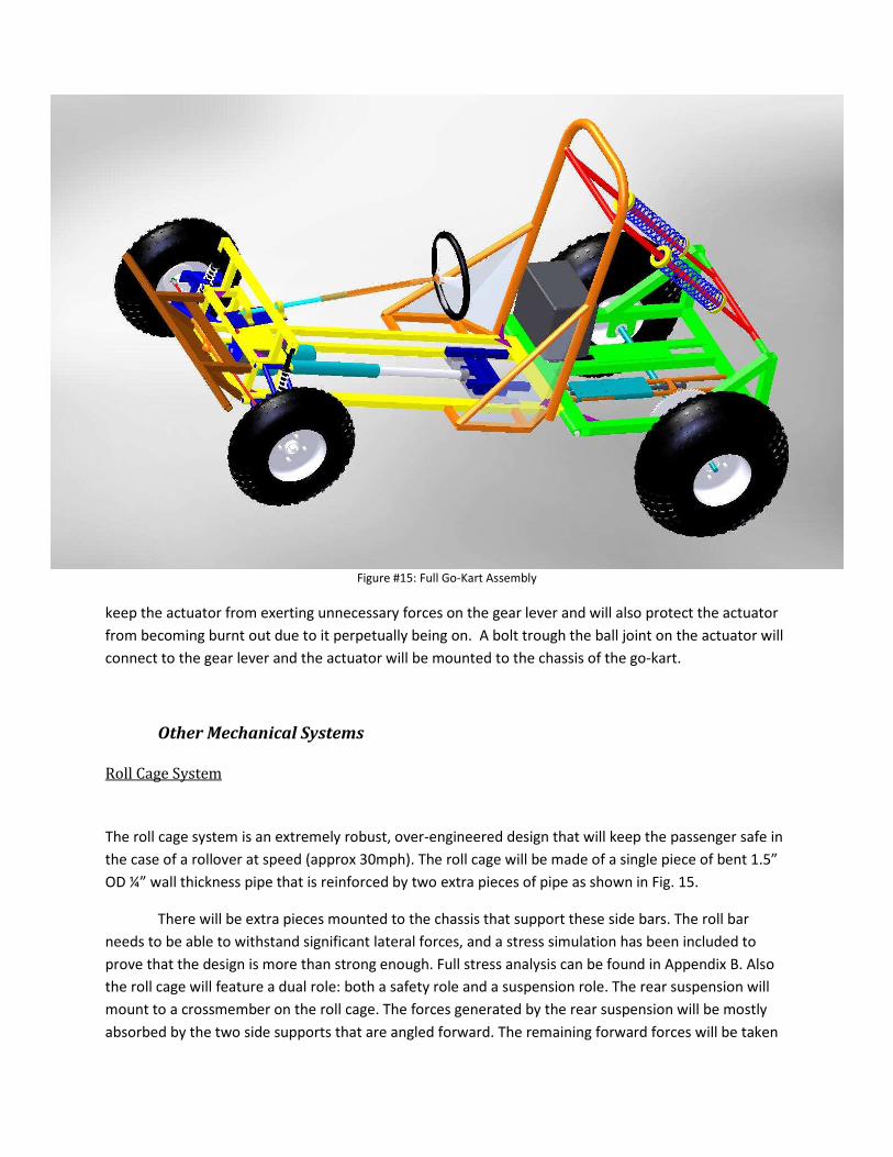
Figure #15: Full Go-Kart Assembly
keep the actuator from exerting unnecessary forces on the gear lever and will also protect the actuator
from becoming burnt out due to it perpetually being on. A bolt trough the ball joint on the actuator will
connect to the gear lever and the actuator will be mounted to the chassis of the go-kart.
Other Mechanical Systems
Roll Cage System
The roll cage system is an extremely robust, over-engineered design that will keep the passenger safe in
the case of a rollover at speed (approx 30mph). The roll cage will be made of a single piece of bent 1.5”
OD ¼” wall thickness pipe that is reinforced by two extra pieces of pipe as shown in Fig. 15.
There will be extra pieces mounted to the chassis that support these side bars. The roll bar
needs to be able to withstand significant lateral forces, and a stress simulation has been included to
prove that the design is more than strong enough. Full stress analysis can be found in Appendix B. Also
the roll cage will feature a dual role: both a safety role and a suspension role. The rear suspension will
mount to a crossmember on the roll cage. The forces generated by the rear suspension will be mostly
absorbed by the two side supports that are angled forward. The remaining forward forces will be taken
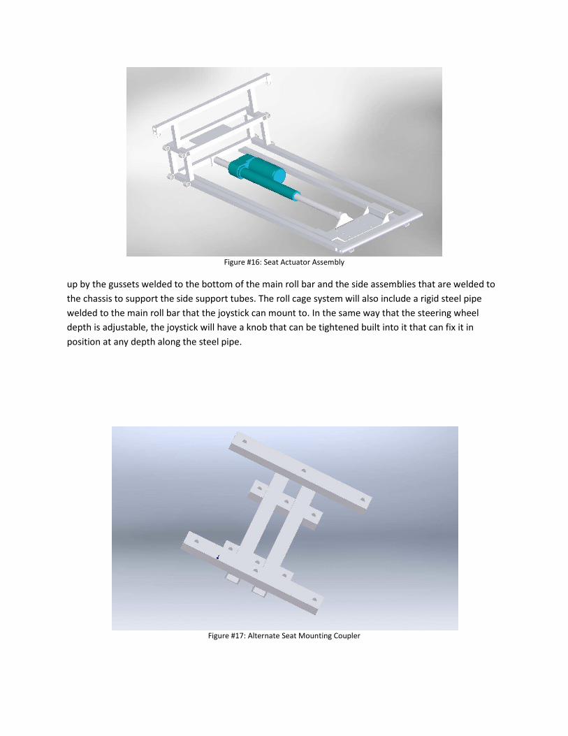
Figure #16: Seat Actuator Assembly
up by the gussets welded to the bottom of the main roll bar and the side assemblies that are welded to
the chassis to support the side support tubes. The roll cage system will also include a rigid steel pipe
welded to the main roll bar that the joystick can mount to. In the same way that the steering wheel
depth is adjustable, the joystick will have a knob that can be tightened built into it that can fix it in
position at any depth along the steel pipe.
Figure #17: Alternate Seat Mounting Coupler

Seat System
The seat system is designed to be adjustable and strong. The seat mounting plate has to be
strong enough to control the passenger’s inertia, as it is the only real structural interface between the
passenger and the vehicle. In order to accomplish both strength and adjustability, a heavy duty linear
actuator has been chosen to move the seat mounting plate forward and backward on two strong,
reinforced steel rails. The seat mounting plate is fixed laterally by the geometry of the rails and the
up/down movement is restricted by tabs and angle iron welded to the seat mounting plate. The linear
actuator is rated for 750lbs, which is more than any passenger that can fit in the vehicle can possibly
weigh. The linear actuator setup can be seen in Fig. 16.
The seat coupler for the seat mounting plate will be made out of steel, and there will be two
separate couplers, one for the normal seat for test driving, and one for the special seat for the client.
The bracket for the normal seat has been designed and looks Fig. 17. The seat coupler for the client’s
special car seat will be the reciprocating piece to the bracket currently mounted to the bottom of their
seat, which looks like Fig. 18. The seat area will be protected from tree-branches, and other off-road
debris by side panels made out of fiberglass. Also, the seat area will have the roll bar support arms
running along the edges, which will completely encase the passenger with structural supports in the
case of a rollover, making them much safer.
Figure #18: Seat Bracket

Duff-Norton LSPD 2775-12
The Duff-Norton LSPD 2775-12 linear actuator will be used to adjust the seat position on the go-
kart. This motor has a 750 pound capacity and a 12 inch stroke arm. The operating voltage of this
particular actuator is 12 volts, corresponding to the voltage of the battery used in this project. The
maximum current draw for this actuator is about 14 amps when the actuator is applying 750 pounds of
force. Current will only be drawn when the seat is being adjusted so the 14 amp draw is acceptable
even through the alternator is only supplying 7 amps of current to the battery. The speed at which the
seat will be adjusted will be comparable to that of adjusting a standard electric car seat. The actuator
will extend or contract based upon the direction of current flow through the actuator. Two internal limit
switches which will stop current from flowing when the actuator has reached the extremes of its stroke.
These limit switches will help to keep the actuator from being damage during usage. One side of the
actuator will be bolted to the seat mounting bracket, pushing it along rails which the mounting bracket
rests on. The other side of the actuator will be attached to the frame of the go-kart.
Figure #19: Front Suspension Arm Assembly
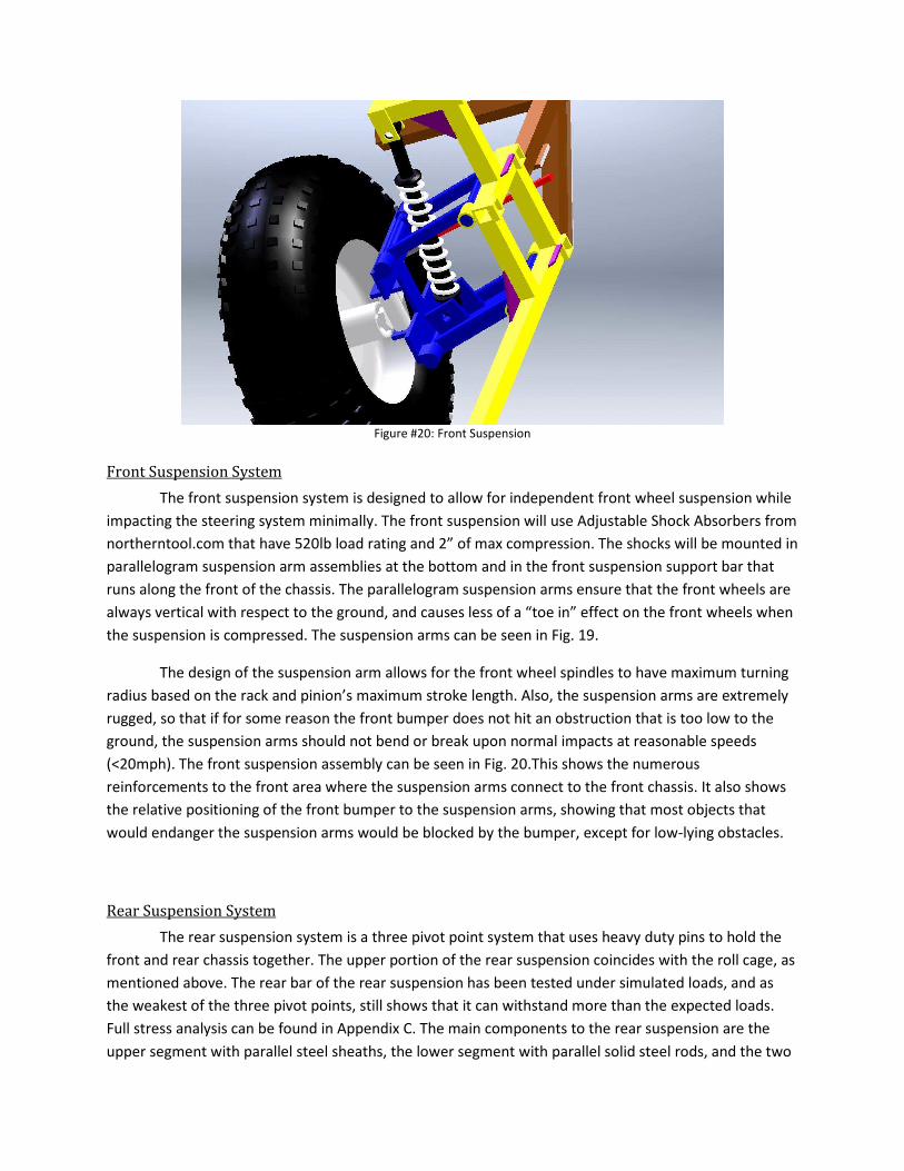
Figure #20: Front Suspension
Front Suspension System
The front suspension system is designed to allow for independent front wheel suspension while
impacting the steering system minimally. The front suspension will use Adjustable Shock Absorbers from
northerntool.com that have 520lb load rating and 2” of max compression. The shocks will be mounted in
parallelogram suspension arm assemblies at the bottom and in the front suspension support bar that
runs along the front of the chassis. The parallelogram suspension arms ensure that the front wheels are
always vertical with respect to the ground, and causes less of a “toe in” effect on the front wheels when
the suspension is compressed. The suspension arms can be seen in Fig. 19.
The design of the suspension arm allows for the front wheel spindles to have maximum turning
radius based on the rack and pinion’s maximum stroke length. Also, the suspension arms are extremely
rugged, so that if for some reason the front bumper does not hit an obstruction that is too low to the
ground, the suspension arms should not bend or break upon normal impacts at reasonable speeds
(<20mph). The front suspension assembly can be seen in Fig. 20.This shows the numerous
reinforcements to the front area where the suspension arms connect to the front chassis. It also shows
the relative positioning of the front bumper to the suspension arms, showing that most objects that
would endanger the suspension arms would be blocked by the bumper, except for low-lying obstacles.
Rear Suspension System
The rear suspension system is a three pivot point system that uses heavy duty pins to hold the
front and rear chassis together. The upper portion of the rear suspension coincides with the roll cage, as
mentioned above. The rear bar of the rear suspension has been tested under simulated loads, and as
the weakest of the three pivot points, still shows that it can withstand more than the expected loads.
Full stress analysis can be found in Appendix C. The main components to the rear suspension are the
upper segment with parallel steel sheaths, the lower segment with parallel solid steel rods, and the two

Figure #21: Rear Suspension
14” coil-over off road springs that interface the upper and lower segments. The idea is that the springs
will provide much of the support for the rear suspension, but the space between the steel sheath and
solid steel rod will be greased, trapping air in the hollow segment above the solid steel rods. This air will
act as a further dampener for the suspension when experiencing jarring impacts, and will improve the
quality of the rear suspension by increasing the force required to bottom out the suspension. This
suspension assembly can be seen in Fig. 21.
Figure #22: Isometric Wire View
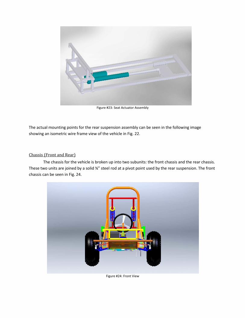
Figure #23: Seat Actuator Assembly
The actual mounting points for the rear suspension assembly can be seen in the following image
showing an isometric wire frame view of the vehicle in Fig. 22.
Chassis (Front and Rear)
The chassis for the vehicle is broken up into two subunits: the front chassis and the rear chassis.
These two units are joined by a solid ¾” steel rod at a pivot point used by the rear suspension. The front
chassis can be seen in Fig. 24.
Figure #24: Front View

These chassis are made to be extremely rigid and strong. They are reinforced with 2” side length
right, isosceles triangle gussets at every corner to increase their rigidity. They are however designed to
have a moderate amount of flex in the case of twisting. This is to accommodate the numerous high
energy impacts that the vehicle will probably encounter while driving off road. The risk of making the
chassis resistant to twist is that it could cause a weld joint to snap, since the forces from random off-
roading impacts can be very large. By keeping the chassis rigid in the x-y plane by flexible in the x-z
plane, the front and rear chassis are more suitable to handle the rigors of off roading without sustaining
any structural damage, no matter how rough the terrain.
Front Bumper
The front bumper will be made out of a single solid piece of 1”x1” steel. This should be able to
withstand any impact and transfer the impact to the reinforced front section of the front chassis. The
front bumper can be seen in Fig. 30. Since the front piece will be solid steel, the forces that will hit the
bumper will travel through that piece and into the 4 front bumper support bars. To test if these bas
were up to a severe impact, a stress analysis has been performed on them. Full stress analysis can be
found in Appendix D. The front bumper should be strong enough to withstand any impact from the
vehicle at speeds under 10mph without any significant deformation, and at speeds above 30mph the
front bumper will crumple appropriately, absorbing the energy of the impact like the nose cone of a race
car, making the collision more plastic, and therefore helping to protect the passenger from excessive g
forces.
2. Realistic Constraints
Economic
This engineering project, as with all other design projects, has a set budget which cannot be
adjusted. A larger budget would allow for the purchasing of better components and result in a better
final product. The projected cost of all parts for this go-kart far exceeds the budgetary constraints given,
but will ultimately result in a better design. Luckily, donated and salvaged parts required for this go-kart
are available for free, allowing for the design of better go-kart, while staying under the allocated
funding. It is important to note that if this go-kart were to be manufactured, the free parts would no
longer be available and the cost of the go-kart would increase from $2300 for a prototype to $7000 for a
production model.

Environmental
The 10 HP engine for this go-kart will be gas powered and operation of the go-kart will result in
the release of carbon dioxide and other emissions from the combustion engine. Other components of
the go-kart are also known to be potential hazards to the environment. The Die Hard battery used to
supply power to the electrical components of the go-kart contains materials that are corrosive and
dangerous. Electronic components can also be hazardous to the environment and in the event of a
malfunction, the proper disposal of any circuit boards is required. Since this go-kart is going to be
operated in the outdoors, it must be driven carefully so the terrain is not excessively damaged.
Outdoor operation also requires that the go-kart be built in such a way so that environmental
factors do not hinder its operation. Water can cause electrical components to short, so all electrical
components must be protected from any type of moisture. This includes waterproofing the circuit
board with the logic units, speed controller, and h-bridge. Mechanical components must be protected
from dirt, dust, water, or any other environmental factors which could hinder their operation.
Gearmotors, linear actuators, and servos need to be encased in a way such that the environment does
not limit the function of the component. The gas engine for this project was chosen because it was
specifically made to endure off road and outdoor conditions. Some of the components of this go-kart
are rated for certain temperature ranges and parts that are suitable for outdoor temperatures must be
found to ensure proper operation. All components must be shock resistant and able to absorb impacts
if necessary.
Sustainability
As mentioned before, the go-kart will be gas powered and therefore it should be refueled
before operation to obtain the maximum driving time. Depending on the speed at which the go-kart is
operated the operation time will vary greatly. The go-kart will run much longer at a slow to moderate
operating speed as opposed to operating the go-kart at intense speeds. Running the engine not only
propels the go-kart but it also will generate current via the alternator. This will recharge the battery and
provide power for all of the electrical components. Minor maintenance such as changing the oil and
cleaning the go-kart occasionally will extend the lifetime of the vehicle. This go-kart has been designed
to withstand collisions and operate in harsh environments. Under typical driving conditions the go-kart
should operate without fail for a long time with the proper maintenance and care.
Manufacturability
Obtaining the majority of the parts for this go-kart would pose little challenge if it were to be
manufactured on a large scale. If a particular part such as the Motion System linear actuator was not

longer manufactured or could no longer be found, a suitable replacement would be easy to find. With a
parts list, the proper mechanical and wiring diagrams, and the code needed to program the
microprocessors, the majority of the go-kart ready to go. However, the chassis for this go-kart is custom
made and would have to be fabricated in order to make a new go-kart. With the CAD files for the go
cart the materials to make the frame it would be possible to manufacture the frame and install all of the
components on the frame with little challenge.
Health and Safety
The primary concern of this project and most other engineering projects are safety. The
intended operator of this go-kart is a child with Cerebral Palsy. Having any child operate a go-kart or
other motorized vehicle has the potential to be dangerous, compounded with the fact that this child has
under developed motor skills means that this go-kart has to be designed with the highest safety
standards in mind. This go-kart is designed with multiple control methods. The onboard controls can be
overridden at any time by a remote operator in the event that the driver is in danger, i.e., about to crash
or roll the vehicle. The wheel base of the go-kart is wide and weight is distributed as low as possible to
ensure that the go-kart cannot roller over. In the unlikely event that the go-kart does roll over, a roll bar
able to withstand thousands of pounds of force will protect the driver. The chassis of the go-kart has
been designed to withstand impacts without deforming or breaking. A multi-point harness will secure
the driver safely in the seat and keep them from being ejected from the vehicle. A two kill switches
have been included in the design, one remote and one onboard, which will stop the gas engine and
apply the brake in the event of an emergency. A speed governor has been implemented into the system
which will limit the maximum speed of the go-kart. The operator will be able to select between a low,
medium, or high speed. A logic unit with multiple processing units has been designed in a way that if
one component were to fail, the system would shut down safely. The go-kart has been designed to
operate under a variety of environmental conditions so malfunction due to water, dirt, or temperature
is unlikely.
Social
One of the main goals of this project is to allow a disabled child to provide a release from the
daily hardships of life and to give them a way to interact with the surrounding world. Building this go-
kart allows them to live life as a normal child would and show that there really are not many differences
between an average child and a child that suffers from a disability. This go-kart is build in such a way
that it could be operated by anyone, disabled or not, and when looking at the design it would not look
any different than a normal go-kart that could be purchased.

3. Safety Issues
Safety, as mentioned earlier, is the primary concern of this project. This requires that the
operator be safe at all times whether they be sitting in the vehicle or anywhere nears the go-kart.
Starting with the electrical systems, all wires carrying a current will be routed through conduits to
protect the wires from environmental hazards, but also protect the operator from any currents the
wires may be carrying. The conduit will be secured to the chassis so the operator will not become hung
up in it when operating the vehicle, or trip over it when entering or exiting the vehicle. There will be no
bare wires anywhere in the go-kart. This will prevent any arcing that could potentially start a fire. All
electrical equipment used in the go-kart is rated for currents that are higher than what will be
experience during the operation of the go-kart. This will keep components from overheating and
catching fire. For the mechanical components of the go-kart, all moving parts will be situated in a way
that it would be impossible for the operator to become caught in them. A chain guard will protect the
chain from being dislocated as well as protecting the operator from accidently becoming caught in the
chain. The steel chassis will protect both the components of the go-kart as well as the operator of the
go-kart in the event of a collision. The roll bar provides protection in the case of a roll over. All part on
the go-kart will be secured to the chassis and there will be no parts that could become dislodged and
come off during operation. The engine, gearbox, and torque converter have been located in a position
that is inaccessible to the operator during operation of the vehicle. It will not be possible for the
operator to become caught in the belt of the torque converter based on its location and where the
driver will be positioned when operating the go-kart. The chemical hazards of this project include
corrosive materials leaking from the battery, gasoline in the engine, and oil also for the engine. It is
unlikely that the sealed battery will leak any chemicals even in the event of a collision of roll over. The
same is true for the gasoline and oil which should remain inside of the engine or in the gas tank in the
event of an accident. It should be noted that gasoline and oil can be dangerous is swallowed or come in
contact with cuts, and also pose a fire hazard if there is a fire nearby when refueling the vehicle or
adding engine oil. Other chemical hazards are from the emissions of the vehicle. The go-kart should not
be operated inside, especially if there is not adequate ventilation, as this poses a major health risk.
Thermal hazards include warm electronic components and a hot engine exhaust. To keep electrical
components as cool as possible, active cooling will be employed on the speed controller and h-bridge.
Both of these components are rated to operate under currents well above the conditions present in the
go-kart. This will also keep the components from overheating. These components will be encased in
ventilated boxes to keep the operator from accessing them when they could potentially be hot. The
engine exhaust will be situated in a way that the operator will not be able touch it when operating the
vehicle. It is also well known that the exhaust on a vehicle is hot to the touch and should not be touched
during operation or after operation until it has had time to cool down.

4. Impact of Engineering Solutions
There should be little to no impact based upon the engineering solutions present in this design.
This go-kart is intended to be operated by a single client and was designed specifically based on the
needs of the client. However, in the event that this go-kart becomes mass produced there could be
some considerable effects on economics, society, the environment, and even far reaching global effects.
This go-kart could potentially provide a release for any physically handicapped person and it was
designed to cost less than other go-karts that have electronic controls. The market for this product is
large and there currently are no suitable designs that can provide the same function as this go-kart. By
creating a new product for a market that has no other products like it, this go-kart has the potential to
make a lot of money for the manufacturer.
If this product were to be purchased by a multitude of people, then society would begin to see
disabled people in a new way. They would be seen out riding in go-karts, enjoying activities that which
are normally reserved for non-disabled people. Handicapped people would be seen as not being all that
different and the differences between people would become less apparent. On the whole society could
become more understanding, more accepting, and less judgmental.
The environmental impact is not favorable however. These go-karts are gas powered and
release carbon dioxide and other emissions into the atmosphere. Whether or not these emissions lead
to global warming has yet to be adequately determined, however it is known that these emissions can
lead to acid rain, smog, and unhealthy air to breath. Disposing of a go-kart with these electrical
components would be cause trouble as well. Just as a laptop computer should not be disposed of in the
garbage, these electrical components should not be just thrown out if the circuits were to malfunction
or the go-kart was to be disposed of. The battery would also need to be disposed of properly as it
contains corrosive materials that cannot just be thrown away. The same goes for the engine oil when it
needs to be changed. Disposing of these materials properly is much better than throwing them out in
the garbage, but even when disposed of properly, some materials cannot be recycled and ultimately
must be thrown out.
This go-kart could potentially have a global impact. The awareness for disabilities on the global
level could rise, resulting in more funding going to research for curing ailments such as Cerebral Palsy.
The acceptance of disabled people on the global level would increase as well. If the go-kart became
popular in other countries that would result in an increase in the products that the United States exports
and bring in more foreign money thereby lowering the trade deficit. The United States would be seen in
a friendlier manner globally. If this go-kart were to become popular in a global setting then it would
lead to improvements and innovations of the go-kart that could be applied to other engineering
specialties.

5. Lifelong Learning
In the course of designing this go-kart many new skills have been developed. Designing the
chassis for the go-kart required a 3D CAD program. The CAD program that was learned was Solidworks
2007 to create parts and put them together. A method for mechanical stress testing of the components
had to be discovered and luckily Solidworks was able to perform this task as well. The system for
steering the go-kart involved the most learning. Three systems of controlling the go-kart had to be
developed that would not interfere with one another. This required acquiring some programming
knowledge in embedded C and how to upload the programs to the processors. In order to be able to
have the gearmotors working in both the forward and reverse directions h-bridges had to be made and
tested to prove that it would be an acceptable method for quickly changing the direction of the
gearmotors. Other options had to be researched as well for this task and the principles behind relays
and how to incorporate relays into circuit had to be looked into. The both the speed controller for
steering the go-kart and the h-bridge for the braking system take PWM signals as their inputs.
Understanding the basic concept of the PWM signal and how to apply it to a particular situation had to
be discovered. After understanding how a PWM signal works a method for getting the processors to
output such signals had to be determined and programming such a method also had to be done. To
generate a smooth ride for the go-kart different types of suspensions had to be investigated. An
independent front suspension and a semi-independent rear suspension was determined to be the best
overall suspension for the purposes of this go-kart. Different engines had to be researched when
choosing the best possible engine for the go-kart. An electrical engine would be the most
environmentally friendly engine, but a gas powered engine like the one chosen for this design is able to
keep the electronics operational without relying on an array of batteries and refueling a gas engine is
much faster than recharging batteries for an electric motor.
Aside from technical aspects that were learned when designing this go-kart, much research
about Cerebral Palsy had to be done, including how it affects a person both physically and mentally.
Understanding how our client was affected helped to determine how the go-kart needed to be designed
in terms of control methods and how his body would be positioned. A body position with the thighs and
chest at a 90 degree angle was discovered to be the optimal body position and the client’s arms needed
to be as close to their body as possible. Maintaining this position allows the client to have the best
control over their arms and legs.
6. References
1. Alex Peslak, Alex Kattamis and Steve Ricciardelli. “E-Racer: An Electric Go-Kart.” University of
Connecticut. NSF 2001 Engineering Senior Design Projects to Aid Persons with Disabilities.
Retrieved on 25 September 2008.
<http://www.engin.swarthmore.edu/academics/courses/e90/2005_6/E90Reports/EK_DM_final
.pdf>
2. Joel G. Landau, James J. LaPenna and Todd M. Piche. “Recreational Electra-Scooter for Special
Children: A Fixed-Radius-Turn, On-Off-Control Wheelchair Carrier.” State University of New
York-Buffalo. NSF 1994 Engineering Senior Design Projects to Aid the Disabled. Retrieved on 25
September 2008. <http://nsfpad.bme.uconn.edu/1994/chapter_8.pdf>.
3. Kevin Arpin, Michael Marquis, Allison Meisner and Travis Ward. “E-Racer.” University of
Connecticut. NSF 2008 Engineering Senior Design Projects to Aid Persons with Disabilities.
Retrieved on 25 September 2008.
<http://www.bme.uconn.edu/sendes/Spring08/Team3/PDFs/291%20Final%20Report.pdf>.
4. “Go-Kart by Mobility4Kids.” ABLEDATA. Retrieved on 25 September 2008.
<http://www.abledata.com/abledata.cfm?pageid=113583&top=0&productid=160295&trail=0>
5. Roberts, Keith Alan. “Handi-Driver.” United States Patent Application Publication. Retrieved
on 25 September 2008. <http://www.freepatentsonline.com/20020184961.pdf>.
6. “Simple H Bridge information” Retrieved on 20 October 2008
<http://www.robotmarketplace.com/products/RP-SMPH.html >
7. “IFI Thor 883 Speed Controller” Retrieved on 20 October 2008
<http://www.robotmarketplace.com/products/IFI-T883.html>
8. “Tecumseh Formula Horizontal Engine with Electric Start” Retrieved 20 October 2008
<http://www.northerntool.com/webapp/wcs/stores/servlet/ProductDisplay?storeId=6970&pro
ductId=394&R=394>
9. “Gearbox” Retrieved on 20 October 2008 <http://www.mfgsupply.com/m/c/218390A.html>
10. “Torque Convertor” Retrieved 20 October 2008
<http://www.ubuilditplans.com/NEWUBUILDIT.HTML#40>
11. “Dayton Gearmotor” Retrieved 20 October 2008
<http://kingsolar.com/catalog/mfg/dayton/1l469.html>

Appendix A: Gear Stress Analysis
Author: James Paolino
Company: UConn
Date: 10/21/08
1. File Information
2. Materials
3. Load & Restraint Information
4. Study Property
5. Results
a. Stress
b. Displacement
c. Deformation
d. Design Check
6. Appendix
1. File Information
Model
name: drive Gear
Model
location:
C:\Documents and Settings\JFP\My Documents\Solidworks\Senior
Design\drive Gear.SLDPRT
Results C:\Documents and Settings\JFP\My Documents\Solidworks\Senior
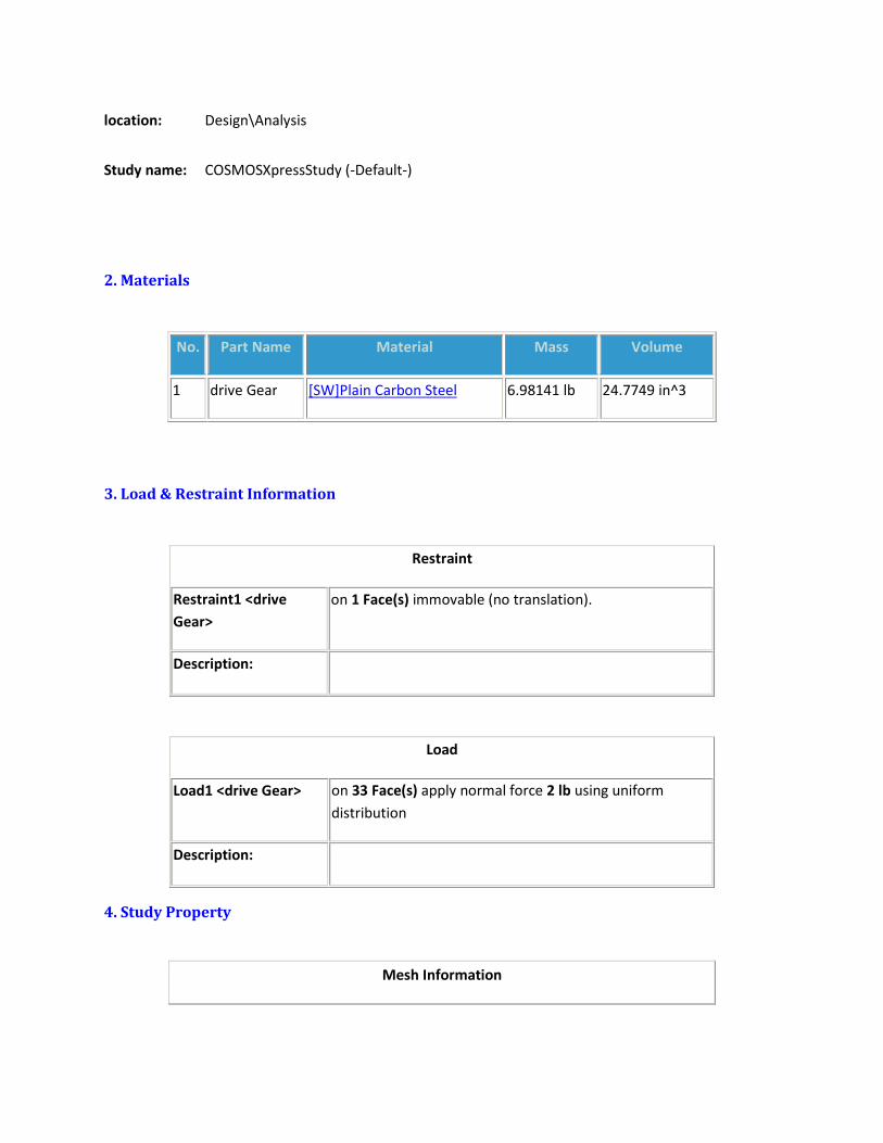
location: Design\Analysis
Study name: COSMOSXpressStudy (-Default-)
2. Materials
No. Part Name Material Mass Volume
1 drive Gear [SW]Plain Carbon Steel 6.98141 lb 24.7749 in^3
3. Load & Restraint Information
Restraint
Restraint1 <drive
Gear>
on 1 Face(s) immovable (no translation).
Description:
Load
Load1 <drive Gear> on 33 Face(s) apply normal force 2 lb using uniform
distribution
Description:
4. Study Property
Mesh Information

Mesh Type: Solid mesh
Mesher Used: Standard
Automatic Transition: Off
Smooth Surface: On
Jacobian Check: 4 Points
Element Size: 0.2916 in
Tolerance: 0.01458 in
Quality: High
Number of elements: 18229
Number of nodes: 33692
Time to complete mesh(hh;mm;ss): 00:00:13
Computer name: JAMES
Solver Information
Quality: High
Solver Type: Automatic
5. Results
5a. Stress
Name Type Min Location Max Location

Plot1 VON: von Mises stress
763.576
N/m^2
(0.25 in,
3.68637
in,
3.64687
in)
1.28308e+008
N/m^2
(0.177083
in,
-0.484123
in,
-0.125 in)
drive Gear-COSMOSXpressStudy-Stress-Plot1
JPEG

5b. Displacement
Name Type Min Location Max Location
Plot2 URES: Resultant
displacement
0 mm
(1.125 in,
-0.484123 in,
-0.125 in)
0.19888 mm
(0.25 in,
5.06185 in,
1.39291 in)

drive Gear-COSMOSXpressStudy-Displacement-Plot2
JPEG
5c. Deformation
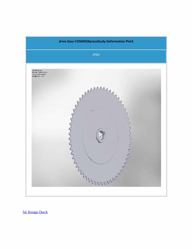
drive Gear-COSMOSXpressStudy-Deformation-Plot3
JPEG
5d. Design Check

drive Gear-COSMOSXpressStudy-Design Check-Plot4
JPEG
6. Appendix

Material name: [SW]Plain Carbon Steel
Description:
Material Source: Used SolidWorks material
Material Library Name:
Material Model Type: Linear Elastic Isotropic
Property Name Value Units
Elastic modulus 3.0463e+007 psi
Poisson's ratio 0.28 NA
Mass density 0.28179 lb/in^3
Yield strength 32000 psi

Appendix B: Roll Bar Stress Analysis
Author: James Paolino
Company: UConn
Date: 10/22/08
1. File Information
2. Materials
3. Load & Restraint Information
4. Study Property
5. Results
a. Stress
b. Displacement
c. Deformation
d. Design Check
6. Conclusion
7. Appendix
1. File Information
Model name: Roll Bar
Model
location:
C:\Documents and Settings\JFP\My Documents\Solidworks\Senior
Design\Roll Bar.SLDPRT
Results
location:
C:\Documents and Settings\JFP\My Documents\Solidworks\Senior
Design\Analysis
Study name: COSMOSXpressStudy (-Default-)
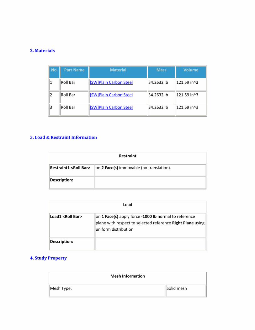
2. Materials
No. Part Name Material Mass Volume
1 Roll Bar [SW]Plain Carbon Steel 34.2632 lb 121.59 in^3
2 Roll Bar [SW]Plain Carbon Steel 34.2632 lb 121.59 in^3
3 Roll Bar [SW]Plain Carbon Steel 34.2632 lb 121.59 in^3
3. Load & Restraint Information
Restraint
Restraint1 <Roll Bar> on 2 Face(s) immovable (no translation).
Description:
Load
Load1 <Roll Bar> on 1 Face(s) apply force -1000 lb normal to reference
plane with respect to selected reference Right Plane using
uniform distribution
Description:
4. Study Property
Mesh Information
Mesh Type: Solid mesh

Mesher Used: Standard
Automatic Transition: Off
Smooth Surface: On
Jacobian Check: 4 Points
Element Size: 0.46765 in
Tolerance: 0.023383 in
Quality: High
Number of elements: 10361
Number of nodes: 20725
Time to complete mesh(hh;mm;ss): 00:00:07
Computer name: JAMES
Solver Information
Quality: High
Solver Type: Automatic
5. Results
5a. Stress
Name Type Min Location Max Location
Plot1 VON: von Mises stress 128355
N/m^2
(21.125
in,
1.87348e+008
N/m^2 (21.25 in,

13.7397
in,
0 in)
0.232878
in,
0 in)
Roll Bar-COSMOSXpressStudy-Stress-Plot1
JPEG

5b. Displacement
Name Type Min Location Max Location
Plot2 URES: Resultant
displacement
0
mm
(-0.433013
in,
0 in,
0.25 in)
4.54771
mm
(9.35526 in,
39.2614 in,
-0.130236
in)
Roll Bar-COSMOSXpressStudy-Displacement-Plot2
JPEG

5c. Deformation
Roll Bar-COSMOSXpressStudy-Deformation-Plot3
JPEG

5d. Design Check
Roll Bar-COSMOSXpressStudy-Design Check-Plot4
JPEG

6. Conclusion
This analysis shows that the roll bar can easily withstand a direct side impact force of 1000lbs without
any extra supports, and since there will be extra supports and the vehicle with a 200lb passenger is
estimated to weigh 750lbs, this means that the roll bar is more than strong enough to withstand a
vehicle rollover with minimal strain effects.
7. Appendix
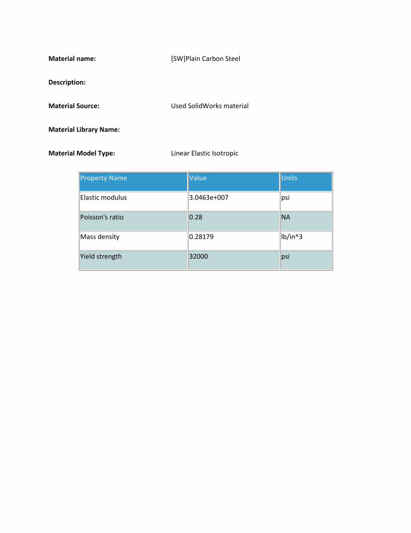
Material name: [SW]Plain Carbon Steel
Description:
Material Source: Used SolidWorks material
Material Library Name:
Material Model Type: Linear Elastic Isotropic
Property Name Value Units
Elastic modulus 3.0463e+007 psi
Poisson's ratio 0.28 NA
Mass density 0.28179 lb/in^3
Yield strength 32000 psi

Appendix C: Rear Suspension Bar Stress Analysis
Author: James Paolino
Company: UConn
Date: 10/22/08
1. File Information
2. Materials
3. Load & Restraint Information
4. Study Property
5. Results
a. Stress
b. Displacement
c. Deformation
d. Design Check
6. Conclusion
7. Appendix
1. File Information
Model
name: Rear Chassis
Model
location:
C:\Documents and Settings\JFP\My Documents\Solidworks\Senior
Design\Rear Chassis.SLDPRT
Results
location:
C:\Documents and Settings\JFP\My Documents\Solidworks\Senior
Design\Analysis

Study name: COSMOSXpressStudy (-Default-)
2. Materials
No. Part Name Material Mass Volume
1 Rear Chassis [SW]Plain Carbon Steel 53.5551 lb 190.051 in^3
2 Rear Chassis [SW]Plain Carbon Steel 53.5551 lb 190.051 in^3
3 Rear Chassis [SW]Plain Carbon Steel 53.5551 lb 190.051 in^3
4 Rear Chassis [SW]Plain Carbon Steel 53.5551 lb 190.051 in^3
5 Rear Chassis [SW]Plain Carbon Steel 53.5551 lb 190.051 in^3
6 Rear Chassis [SW]Plain Carbon Steel 53.5551 lb 190.051 in^3
7 Rear Chassis [SW]Plain Carbon Steel 53.5551 lb 190.051 in^3
8 Rear Chassis [SW]Plain Carbon Steel 53.5551 lb 190.051 in^3
9 Rear Chassis [SW]Plain Carbon Steel 53.5551 lb 190.051 in^3
10 Rear Chassis [SW]Plain Carbon Steel 53.5551 lb 190.051 in^3
11 Rear Chassis [SW]Plain Carbon Steel 53.5551 lb 190.051 in^3
3. Load & Restraint Information
Restraint
Restraint1 <Rear
Chassis>
on 2 Face(s) immovable (no translation).

Description:
Load
Load1 <Rear Chassis> on 1 Face(s) apply force 200 lb normal to reference plane
with respect to selected reference Front Plane using
uniform distribution
Description:
4. Study Property
Mesh Information
Mesh Type: Solid mesh
Mesher Used: Standard
Automatic Transition: Off
Smooth Surface: On
Jacobian Check: 4 Points
Element Size: 0.22569 in
Tolerance: 0.011285 in
Quality: High
Number of elements: 4926
Number of nodes: 8918
Time to complete mesh(hh;mm;ss): 00:00:01
Computer name: JAMES

Solver Information
Quality: High
Solver Type: Automatic
5. Results
5a. Stress
Name Type Min Location Max Location
Plot1 VON: von Mises stress
132946
N/m^2
(-
7.50862
in,
9.71524
in,
28.625
in)
6.90272e+007
N/m^2
(-
12.7759
in,
9.71524
in,
28.625
in)
Rear Chassis-COSMOSXpressStudy-Stress-Plot1
JPEG

5b. Displacement
Name Type Min Location Max Location
Plot2 URES: Resultant
displacement
0
mm
(13 in,
10.04 in,
28.0625
0.492878
mm
(5.2377e-007
in,
9.34594 in,

in)
28.3151 in)
Rear Chassis-COSMOSXpressStudy-Displacement-Plot2
JPEG

5c. Deformation
Rear Chassis-COSMOSXpressStudy-Deformation-Plot3
JPEG

5d. Design Check
Rear Chassis-COSMOSXpressStudy-Design Check-Plot4
JPEG

6. Conclusion
This Analysis shows that the rear suspension bar can withstand a force of 200lbs with a safety factor of
3.2. This is important because the estimated weight of the vehicle is about 750lbs with a 200lb rider, and
the force that the rear suspension bar will see will be about 1/12th of that due to the mechanical design
of where the suspension pins are located and the weight distribution of the vehicle. Using a 200lb force
simulates more than the bar will probably ever see, and the high safety factor of 3.2 proves that it will
be stable.
7. Appendix
Material name: [SW]Plain Carbon Steel
Description:
Material Source: Used SolidWorks material
Material Library Name:
Material Model Type: Linear Elastic Isotropic
Property Name Value Units
Elastic modulus 3.0463e+007 psi
Poisson's ratio 0.28 NA
Mass density 0.28179 lb/in^3
Yield strength 32000 psi

Appendix D: Front Bumper Analysis
Author: James Paolino
Company: UConn
Date: 10/18/08
1. File Information
2. Materials
3. Load & Restraint Information
4. Study Property
5. Results
a. Stress
b. Displacement
c. Deformation
d. Design Check
6. Appendix
1. File Information
Model
name: Front Bumper
Model
location:
C:\Documents and Settings\JFP\My Documents\Solidworks\Senior
Design\Front Bumper.SLDPRT
Results
location:
C:\Documents and Settings\JFP\My Documents\Solidworks\Senior
Design\Analysis
Study name: COSMOSXpressStudy (-Default-)
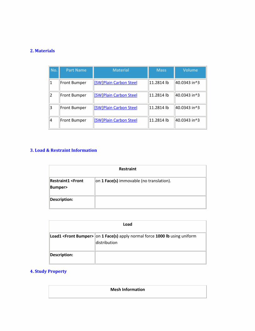
2. Materials
No. Part Name Material Mass Volume
1 Front Bumper [SW]Plain Carbon Steel 11.2814 lb 40.0343 in^3
2 Front Bumper [SW]Plain Carbon Steel 11.2814 lb 40.0343 in^3
3 Front Bumper [SW]Plain Carbon Steel 11.2814 lb 40.0343 in^3
4 Front Bumper [SW]Plain Carbon Steel 11.2814 lb 40.0343 in^3
3. Load & Restraint Information
Restraint
Restraint1 <Front
Bumper>
on 1 Face(s) immovable (no translation).
Description:
Load
Load1 <Front Bumper> on 1 Face(s) apply normal force 1000 lb using uniform
distribution
Description:
4. Study Property
Mesh Information

Mesh Type: Solid mesh
Mesher Used: Standard
Automatic Transition: Off
Smooth Surface: On
Jacobian Check: 4 Points
Element Size: 0.15443 in
Tolerance: 0.0077217 in
Quality: High
Number of elements: 7503
Number of nodes: 15128
Time to complete mesh(hh;mm;ss): 00:00:03
Computer name: JAMES
Solver Information
Quality: High
Solver Type: Automatic
5. Results
5a. Stress
Name Type Min Location Max Location
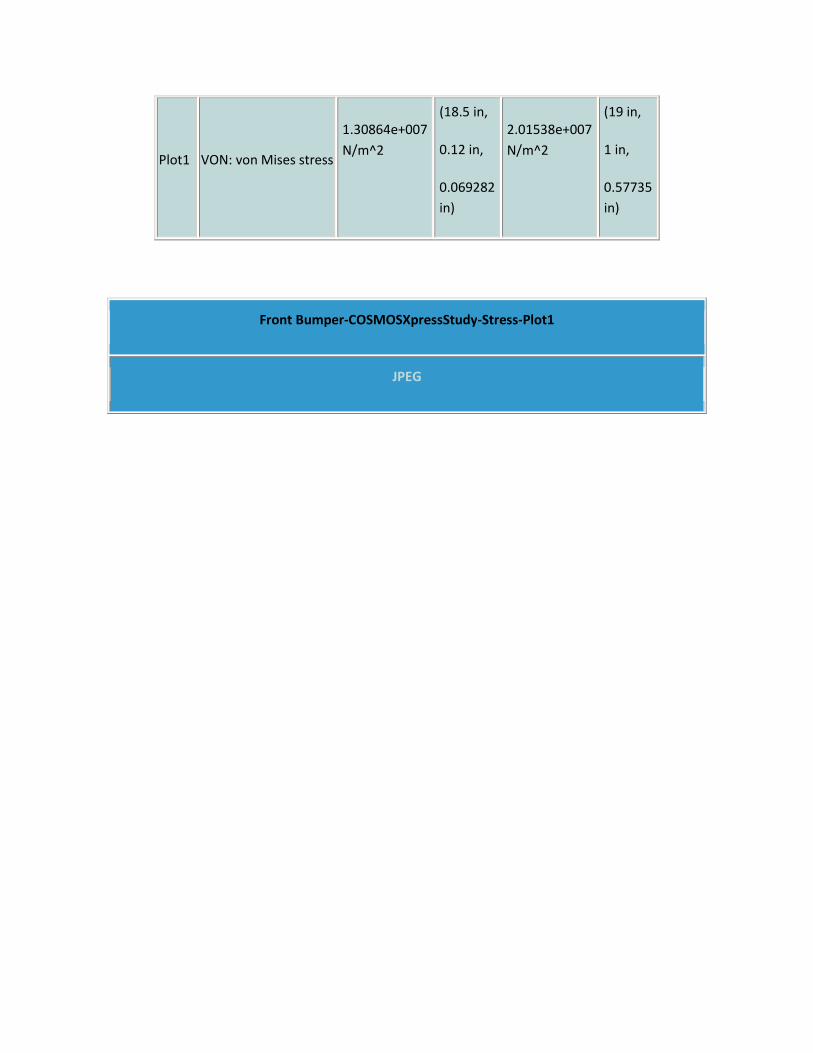
Plot1 VON: von Mises stress
1.30864e+007
N/m^2
(18.5 in,
0.12 in,
0.069282
in)
2.01538e+007
N/m^2
(19 in,
1 in,
0.57735
in)
Front Bumper-COSMOSXpressStudy-Stress-Plot1
JPEG

5b. Displacement
Name Type Min Location Max Location
Plot2 URES: Resultant
displacement
0 mm
(18 in,
1 in,
0.57735 in)
0.0203959 mm
(19 in,
0 in,
9 in)

Front Bumper-COSMOSXpressStudy-Displacement-Plot2
JPEG
5c. Deformation
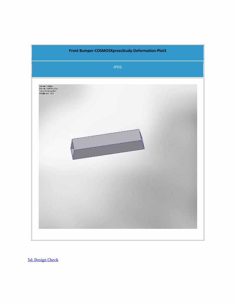
Front Bumper-COSMOSXpressStudy-Deformation-Plot3
JPEG
5d. Design Check
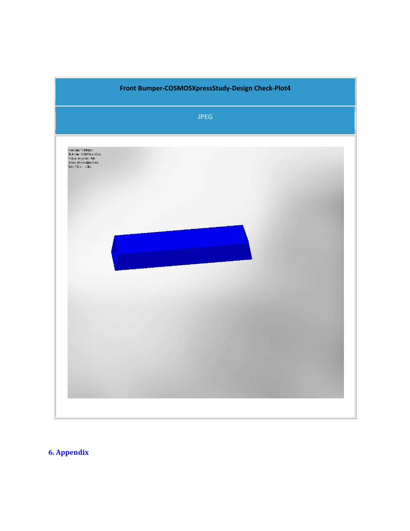
Front Bumper-COSMOSXpressStudy-Design Check-Plot4
JPEG
6. Appendix

Material name: [SW]Plain Carbon Steel
Description:
Material Source: Used SolidWorks material
Material Library Name:
Material Model Type: Linear Elastic Isotropic
Property Name Value Units
Elastic modulus 3.0463e+007 psi
Poisson's ratio 0.28 NA
Mass density 0.28179 lb/in^3
Yield strength 32000 psi