the role of isolation transformers in ups systems · the role of isolation transformers in ups...
TRANSCRIPT

APC by Schneider Electric – Name – Date
The Role of Isolation
Transformers in UPS Systems

APC by Schneider Electric – Name – Date
Real role of a transformer (UPS output) Output UPS Voltage adaptation
2
Standard SCR rectifier cannot deliver a high DC voltage
Rectifier output DC voltage is limited by AC input voltage
AC Input voltage from main low
voltage electrical
distribution
DC output voltage To inverter input and
battery Theoretically; DC voltage = AC input voltage x
if U main = 400V
VDC = 400 x = 565 V
Typical DC voltage used = 450 volt
2
2

APC by Schneider Electric – Name – Date
Transformerless topology design
Why a transformerless topography?

APC by Schneider Electric – Name – Date
Technological design:
Why a transformerless
topology ?
●Best solution to maximize the triptic :
●Need of 3% thdi Dc Bus at 800 v no need of output
transformer.
Elec.perf
Efficiency Costs
● Better electrical performances
● Total compatibility with any electrical design
● Save footprint
● Lower use of row material : environment concern
● Save cost
● Up to date topology : strong trend of current UPS design

APC by Schneider Electric – Name – Date
800 V 230 v
400 v
Voltage elevator from 230v
to 400v
Inverter output voltage accordance with 3 phase electrical distribution system :
400V, 415V
Transformer is no longer useful to adjust output AC voltage
400V /415V
Electronic regulation allow an accurate
and wide range of voltage adaptation
capability
Technological design:
New generation of IGBT rectifier

APC by Schneider Electric – Name – Date
800 V 230 v
400 v
Voltage elevator from 230v
to 400v
Chock of the Transformer is no longer useful in the output filter
400V /415V
Output LC filter still exist
Free-frequencyswitching
Qualityband withvariations< 1%
Output voltagecurve
Up to 8 commutationsper millisecond
Technological design:
New generation of IGBT rectifier

APC by Schneider Electric – Name – Date
DC voltage at the output of
the UPS
caused by a problem of electronic
regulation
Transformer can supply only up till 5 % of DC current
Transformerless UPS can supply up
till 10% of DC Current
DC current at the output of
the UPS
(power supply with only one diode)
Electronic regulates to have no DC
voltage.
If electronic trouble, control loop orders a transfer to by-
pass
UPS inverter fault
between phase or on DC
Bus
Only electronic regulation can guaranty
the non transmission to the load
Transformerless UPS DC voltage output : Electronic regulation
According to UPS standards, regulation and verification are separate functions from
two independent devices

APC by Schneider Electric – Name – Date
Low frequency disturbances
: Lightning , over voltage
High frequency
disturbances « arcing »
EMC of transformeless UPS doesn’t change from what was done with transformer
based on EMC filter installed on both Rectifier and by pass input and on UPS
output
EMC
Filters
Transformerless UPS
EMI disturbances :
EMC
Filters
EMC filters
APC by Schneider Electric – Name – Date
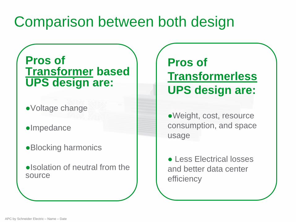
Comparison between both design
Pros of Transformer based UPS design are:
●Voltage change
●Impedance
●Blocking harmonics
●Isolation of neutral from the source
Pros of
Transformerless
UPS design are:
●Weight, cost, resource
consumption, and space
usage
● Less Electrical losses
and better data center
efficiency

APC by Schneider Electric – Name – Date
When is a Transformer really needed?
The key functions resulting
from isolation are: ● Changing different mains grounding
systems
● Creating a new neutral connection
● Combining two sources
● Preventing circulating currents

APC by Schneider Electric – Name – Date
Definition Electrical security policy
●According to IEC 60364 international standard
●The first letter defines the neutral position
● T Neutral is linked with the local earth
● I Neutral is isolated
●The second letter defines the ground position
● T Ground are linked to earth
● N Ground are linked to the Neutral
●The third letter defines the neutral position within TN mode
● C Neutral and Ground are Common
● S Neutral and Ground are Separated
T N
T N
T N C

APC by Schneider Electric – Name – Date
3
2
1
N
PE
T T Neutral is linked to the earth
Grounding network linked to the earth
TT system
Long distance
Separated building

APC by Schneider Electric – Name – Date
3
2
1
N
PE
T N Neutral is linked to the earth
Equipment grounding linked to the neutral
TNC TNS
TN system

APC by Schneider Electric – Name – Date
3
2
1
N
PE
I T
Neutral is isolated from the earth
Equipment grounding linked to the earth
IT system
industrial environment.

APC by Schneider Electric – Name – Date
Neutral system comparison
PE
3P+N
PE
3P+N
R
B R
A
TN system Tertiary
TT system Home/low power
IT system Industrial/Hospital CB control after 2 faults
3
2
1
N
PE
CPI

APC by Schneider Electric – Name – Date
Grounding systems arrangement:
The different cases
TNC TNS TT IT
TNC
2% - If long cables, save
costs on number of wires.
Grounding system change
if necessaru at down strem
electrical panel.
No
transformer
1 compulsory
transformer at the
ouput or 2
upstream (Mains 1
and 2) transformers
1 compulsory
transformer at the
ouput or 2
upstream (Mains 1
and 2) transformers
1 compulsory
transformer at the
ouput or 2 upstream
(Mains 1 and 2)
transformers
TNS
85% -
recommanded
for IT loads
No
transformer (separate cables
upstream or
downstream
UPS)
Recommandation
of 1 tansformer at
the ouput or 2
upstream
transformers
(Mains 1 and 2)
1 compulsory
transformer at the
ouput or 2
upstream (Mains 1
and 2) transformers
1 compulsory
transformer at the
ouput or 2 upstream
(Mains 1 and 2)
transformers
TT
3% - Public buildings
1 compulsory
transformer at the
ouput or 2
upstream (Mains
1 and 2)
transformers
1 compulsory
transformer at the
ouput or 2
upstream (Mains 1
and 2) transformers
Recommandation
of 1 tansformer at
the ouput or 2
upstream
transformers
(Mains 1 and 2)
1 compulsory
transformer at the
ouput or 2 upstream
(Mains 1 and 2)
transformers
IT
10% - Industry
environment or non IT loads
1 compulsory
transformer at the
ouput or 2
upstream (Mains
1 and 2)
transformers
1 compulsory
transformer at the
ouput or 2
upstream (Mains 1
and 2) transformers
1 compulsory
transformer at the
ouput or 2
upstream (Mains 1
and 2) transformers
Recommandation
of 1 tansformer at the
ouput or 2 upstream
transformers (Mains
1 and 2)
UPSTREAM UPS
DO
WN
ST
RE
AM
UP
S

APC by Schneider Electric – Name – Date
Transformer Isolation
Changing Different Mains Grounding
Systems is an essential function
IT equipment = TN-S
TT/IT require conversion to TN-S
transformer

APC by Schneider Electric – Name – Date
Earthing system arrangement
AC normal AC By-Pass Upstream UPS downstream UPS
Separated
Come from same source (1)
Same earthing system arrangement
. . .
(1)
Neutral distributed

APC by Schneider Electric – Name – Date
Earthing system arrangement
AC normal AC By-Pass Upstream UPS downstream UPS
Separated
Come from same source (1)
Same earthing system arrangement
(1)
Neutral not distributed
Comments
Transformerless UPS can work
without neutral
Application : 3 phases loads
. .

APC by Schneider Electric – Name – Date
Earthing system arrangement
AC normal AC By-Pass Upstream UPS downstream UPS
Separated
Come from same source (1)
Different earthing system
. .
(1)
Comments
Add one output transformer
Transformer reliability is high : not a single
point of failure
TFO MTBF = 2 millions hours
UPS MTBF = 475,000 hours
. . .
AC By-Pass and AC normal come
from same source : 94%
Changes of grounding system arrangement
upstream/downstream : 30%
28%

APC by Schneider Electric – Name – Date
Earthing system arrangement
AC normal AC By-Pass Upstream UPS downstream UPS
Common Different earthing system
(1)
Add one input transformer l
Efficiency is lower by 1%
Size of the transformer : Pn
. .
AC By-Pass and AC normal come
from same source : 94%
Changes of grounding system arrangement
upstream/downstream : 30%
28%
Comments
APC by Schneider Electric – Name – Date
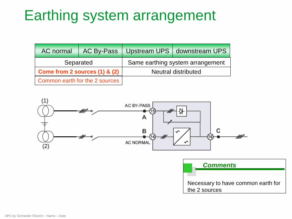
Earthing system arrangement
AC normal AC By-Pass Upstream UPS downstream UPS
Separated
Come from 2 sources (1) & (2)
Same earthing system arrangement
(1)
Neutral distributed
Common earth for the 2 sources
(2)
Comments
Necessary to have common earth for
the 2 sources

APC by Schneider Electric – Name – Date
Earthing system arrangement
AC normal AC By-Pass Upstream UPS downstream UPS
Separated
Come from 2 sources (1) & (2)
Same earthing system arrangement
(1)
Neutral distributed
Different earth for the 2
sources
(2)
Comments
Add one transformer (3)
Not different from PW ?
(3)

APC by Schneider Electric – Name – Date
Earthing system arrangement
AC normal AC By-Pass Upstream UPS downstream UPS
Separated
Come from 2 sources (1) & (2)
Different earthing sys. arrangement
(1)
Neutral distributed
Common earth for the 2 sources
(2)
Comments
Add 1 transformers (3)
(3)
AC By-Pass and AC normal come from 2 different
sources : 6%
Changes of grounding system arrangement
upstream/downstream : 30%
1.8%

APC by Schneider Electric – Name – Date
Earthing system arrangement
AC normal AC By-Pass Upstream UPS downstream UPS
Separated
Come from 2 sources (1) & (2)
Different earth. system arrangement
(1)
Neutral distributed
Different earth for the 2 sources
(2)
Comments
Add 2 transformers (3) and (4)
(3)
(4)

APC by Schneider Electric – Name – Date
Transformer Isolation
Shared with other customers
Generated a distance from the
data center
Deemed unreliable
Creating a New Neutral Connection

APC by Schneider Electric – Name – Date
Transformer Isolation
Creating a New Neutral Connection
In developed countries and most
large, new buildings: ● TN-S neutral source is within the customer
premises and close to the data center
● Excellent quality
In other situations: ● Neutral-to-ground bond may be outdoors,
possibly distant, shared, and part of a
degraded/ overloaded system
● Significant offset or noise voltage
● Loss of ground connection or interruption

APC by Schneider Electric – Name – Date
Conclusion
In summary:
●Transformer-based and transformerless
UPS installations include transformers.
●Transformers provide for important
functions.
●Transformers are still, but not always,
necessary in system design.
●Transformer-based UPS systems do not
usually have an optimally placed
transformer.
●Transformer-less UPS systems allow for
the omission or movement to the best
location of transformers.