the richard b. kershner space integration and test …€¦ · the richard b. kershner space...
TRANSCRIPT

ALVIN G. BUSH, WILLIAM E. FRAIN, and ALBERT C. REYMANN
THE RICHARD B. KERSHNER SPACE INTEGRATION AND TEST FACILITY
This article describes the functional characteristics and capabilities of the APL Space Integration and Test Facility. Its design was begun in late 1981, and the building was dedicated on October 11, 1983.
INTRODUCTION The Richard B. Kershner Space Integration and Test
Facility (Fig. 1) provides laboratory and office space to support the assembly and testing of spacecraft and spacecraft-borne instruments. Environmental test facilities within its 79,000 square feet simulate the rigors of launch and of operations in the vacuum conditions of space. The building contains assembly and test rooms that are clean enough so that precision optical equipment will not be contaminated; laboratories for the development of components for attitude control systems, power system electronics, batteries, and solar arrays; reliability and quality assurance laboratories for the inspection of delicate electronics parts and for failure analysis; and office space for 155 engineers, technicians, draftsmen, and secretaries.
At the core of the building's function are areas devoted to the assembly and testing of spacecraft and spacecraft instruments. Five rooms, each with 1000 square feet of floor space, adjoin a staging area served by an overhead crane. Three of the rooms meet Federal Standard clean room requirements of Class 100,000. (These standards will be defined later in this article.) Two rooms are 10 times cleaner, i.e., Class 10,000. Adjacent to that area are two rooms, each with a 240 square foot floor area, that are maintained at Class 100, suitable for the assembly of small space instruments containing delicate optics and particle detectors or as sterile rooms for the assembly of implantable biomedical devices.
Joining the assembly and test area are the Space Simulation and the Vibration Test Laboratories. The former contains vacuum chambers for simulating the vacuum and temperature conditions of space and a temperature, humidity, and altitude chamber to simulate environmental extremes on earth. The Vibration Test Laboratory has shakers for vibrating and shocking test articles, thereby simulating environments common to launch vehicles, missiles, and aircraft.
Smaller laboratories serve the Satellite Reliability Group. There, new parts are inspected and parts that may have failed to operate properly are analyzed. Nearby are a stockroom for bonded storage of flight hardware and a solar simulation laboratory where spacecraft solar array performance (electrical output characteristics) can be tested.
Johns Hopkins APL Technical Digest, Volume 6, Number 1
Figure 1-The Richard B. Kershner building contains offices, laboratories, and clean rooms. It is the point of final assembly and qualification of spacecraft and space instrumentation.
Space allocation and layout (Fig. 2) were determined by the requirement for the flow, under one roof, of individual parts from a certified clean stockroom through acceptable assembly areas to the environmental test areas.
CLEAN ROOM TECHNOLOGY A clean room is defined by Federal Standard No.
209B.l It is one with a controlled environment in which filtering, room structure, and work discipline will ensure that no more than a specified number of particles greater than a specified size are contained in a given volume of the room air. For example, a Class 100,000 clean room can contain no more than 100,000 particles, 0.5 micrometer in size or larger, per cubic foot of air. The sources of contamination (Table 1) in these rooms are primarily people (skin scales and clothing lint) and equipment (wear particles and previously accumulated dust). A typical inactive office might contain 100,000 0.5 micrometer and larger particles per cubic foot. But if 0.3 micrometer size particles are considered, the count goes up to 550,000 per cubic foot. And if the office is active, the count can increase by a factor of 10. A measurement made outside the southeast entrance to the Kershner building on a summer afternoon with a clear sky and no wind yielded 714,000 half-micrometer or larger particles per cubic foot. If 0.3 micrometer particles had been counted also, the number would have increased to 1,900,000.
85

A. G. Bush et af. - Kershner Space Integration and Test Facility
~ Exits
Third floor
o General office space
o General purpose laboratories o Machinery spaces for air han
dling and conditioning
o Drafting room
Second floor
o General office space
o General purpose laboratories
o Machinery spaces for air handling and conditioning
First floor
o Clean areas for the assembly and test of spacecraft and scientific experiments
o Special purpose laboratories for component and parts screening and test
o Vibration Test Laboratory for testing of spacecraft
o Space Simulation Laboratory for thermal-vacuum testing of spacecraft and spacecraft components
o Machinery spaces for air handling and conditioning
Figure 2-A floor plan showing the layout of clean rooms, offices, and air handling equipment in the Richard B. Kershner Space Integration and Test Facility.
Table 1-Contamination generation.2
Activity
Person standing still Arms, head, and body motion
Walking at 0.9 meter per second
Substantial activity
Particuiote Generation
(per minute, greater than 0.3 micrometer)
100,000
1,000,000
5,000,000 100,000,000
Of the particles, 89 percent were in the 0.3 to 0.7 micrometer size range. The smaller particles will conglomerate as they settle if they are not flushed away with air flow.
Figure 3 gives an idea of the relative sizes of many common airborne contaminants. High-efficiency particulate air filters capable of filtering out any particle or contaminant larger than 0.3 micrometer in size are used to purify the air for clean rooms (Fig. 4).
The highest quality and most costly clean rooms are those with laminar air flow, either vertical or horizon-
86
tal (Fig. 5). Such rooms provide a constant flow of evenly distributed air across the entire area. In a vertical laminar flow room, air flows evenly from all areas of the ceiling to all areas of the floor and through the floor to the return plenum. The horizontal laminar flow room functions in a similar fashion except that flow is from one wall to and out the opposite wall. The two Class 10,000 rooms of the integration and test area of the Kershner Building are horizontal laminar flow rooms, and the two smaller, Class 100 rooms have a modified vertical laminar flow. The latter have an even air flow out of the entire ceiling area, but modified so that the air is returned via the bottom edge of one wall rather than through the floor area. This provides almost as good a result at the bench working levels as a true vertical laminar flow room without the necessity of a grating-type floor for the air exhaust.
Other, more conventional clean rooms are designed with diffusers in the ceilings and air returns around the bottom of the walls. With this design, however, the air flow is downward, then outward to the bottom of the walls as in a modified vertical laminar flow room, producing more air turbulence than in a laminar flow room. The Class 300,000 clean rooms (the Space Simulation and Vibration Laboratories) are similar except that the air is returned through grills located at various points around the rooms.
Johns Hopkins APL Technical Digest, Volume 6, Number 1

Atmospheric dust
Sea fog
Aerosols ------------Mist and raindrops
Meta llurgical dust and fumes
Ammon ium chloride fumes - Ground limestone
Limek i ln dust
Sulfuric acid mist and fumes
Cement dust
Zinc oxide fumes
Coal smoke
I nsecticide dust
Bacteria
Pollens -Tobacco smoke Asphalt paving plant dust
. Soot blowing; boiler tubes Magnesium _______ _
oxide smoke Sand tail ings
Ferti I izer plant dust and fu mes
Res in smoke Human hair diameter
Pa i nt p ig,.m.e .. nt.s __ _
Condensation nuclei -Sea sa lt nuc lei -t average
0.0001 0.001 0.01 0.1 10 100 1000 10,000 Micrometers
Figure 3-Sizes of many common airborne contaminants.
Figure 4-Section of a high-efficiency particulate air filter. Its efficiency is approximately 99.97 percent for filtering 0.3 micrometer and larger particulates.
The same quality of filtered air is supplied to all the clean rooms. The differences in classification come from the way air is supplied, cleaning procedures in
Johns Hopkins APL Technical Digest, Volume 6, Number 1
A. G. Bush et al. - Kershner Space Integration and Test Facility
• Prefilter High-efficiency particulate air filter
--~ .. :j
--~. l} -----+~ i} --t--~ lj -+-+_1J
(a) Vertical laminar flow (b) Horizontal laminar flow
(c) Modified vertical laminar flow
(d) Conventional air flow clean room
Figure 5-Clean room air flow configurations.
the rooms, discipline to keep dirt out, and procedures to prevent dirt from being generated within the room.
Hydrocarbon is another important contaminant. Ultraviolet light instrumentation is particularly sensitive, even to only a few angstroms of a hydrocarbon film. Such films can accumulate on satellite surfaces during fabrication and later migrate to colder surfaces, such as the optics. Because hydrocarbon vapors are not filtered out by the high-efficiency particulate air filters, our approach has been to eliminate, from the start, as many hydrocarbon-generating materials as possible. All building and finishing materials were examined and rejected if they would pose an outgassing problem. The resulting level of hydrocarbons, as measured, is 3 to 5 parts per million of air. Any value below 15 parts per million is acceptable.
QUALITY ASSURANCE The responsibility of the Reliability Group is to
monitor spacecraft hardware development activities and assure that standards of reliability and quality are met. It has the further responsibility to obtain highly reliable parts for hardware fabrication. This procedure starts with the initial design and drafting efforts, when information begins to be fed into a computerized database. As designs progress, parts are purchased. When they arrive, the Reliability Group processes them through a rigorous incoming test and inspection routine with specified high-reliability standards. The operation uses X-ray facilities; computer-controlled test equipment for testing complex integrated digital circuits, diodes, and transistors as well as linear integrated circuits; visual inspection; hermetic leak testing; pas-
87
A. G. Bush et al. - Kershner Space Integration and Test Facility
sive part testing equipment; particle impact noise detection testing; small environmental chambers for automatic thermal cycling; and capabilities for' 'burning in" parts with power applied. There are also a small ultra-high vacuum chamber and a cobalt-60 irradiator for special testing. Two of the test laboratories are shown in Figs. 6 and 7.
One Class 100,000 conventional clean room is used as the Destructive Physical Analysis and Failure Analysis Laboratory. In those areas, all parts are fully tested according to specified requirements. Special precautions are taken to ensure that no electrostatic damage is incurred in processing. The floors are made of conductive material and are grounded to prevent static buildup. Laboratory benches and workers are also grounded when static-sensitive parts are being worked on. Workers are required to wear conductive, lint-free smocks while in the clean room areas, both to reduce electrostatic risks and to conform to clean room requirements.
When received, parts are logged into the tracking system and followed throughout the testing. As testing is completed, the parts are placed in the bonded flight stockroom, where the same part-handling requirements are applied.
THE INTEGRATION AND TEST AREAS High-reliability parts issued from the flight stock
room are fabricated into spacecraft hardware, which is subsequently returned to the Kershner Building to join with mechanical structures, cable harness, and test equipment. There the spacecraft is assembled and tested to ensure that it has met the goals of the design. Two computer rooms are connected to the clean rooms to provide instrumentation support.
The integration and test areas have the cleanest rooms in the building. Each of the two Class 100 rooms is constructed as a modified vertical laminar flow room. While they use air from the main air handling and conditioning unit, they have their own highefficiency particulate air filters and prefilters, their own fans, and an air "shower" in the entrance to the rooms. The shower, with multidirectional air nozzles, blows away any remaining contamination on the garments and flushes it out of the system. The floors in the two rooms are covered with conductive epoxy for cleanliness and for electrostatic discharge protection. A source of dry nitrogen is available in each room, as well as a connection to the central vacuum system for cleaning purposes.
One of the rooms has been' 'scrubbed down" and is used as a sterile room. It requires a very strict discipline so that bacteriological contamination will riot be introduced. The sterile room will be used for the assembly and test of biomedical devices before they are implanted into patients at the Johns Hopkins Hospital.
The three-story-high bay that forms the staging area is a Class 100,000 conventional clean room. It measures 30 by 50 feet and is 32 feet high. The high bay section has a 5-ton crane, operable at fast and slow
88
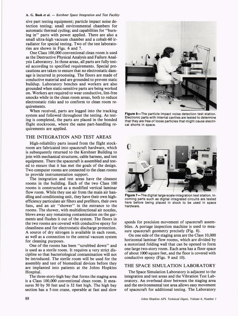
Figure 6-The particle impact noise detection test station. Electronic parts with internal cavities are tested to determine that they are free of loose particles that might cause electrical shorts in space.
Figure 7-The digitallarge·scale-integration test station. Incoming parts such as digital integrated circuits are tested here before being placed in stock to be used in space hardware.
speeds for precision movement of spacecraft assemblies. A portage inspection machine is used to measure spacecraft geometry precisely (Fig. 8).
On one side of the staging area are the Class 10,000 horizontal laminar flow rooms, which are divided by a motorized folding wall that can be opened to form one large two-story room. Each area has a floor space of about 1000 square feet, and the floor is covered with conductive epoxy (Figs. 9 and 10).
THE SPACE SIMULATION LABORATORY The Space Simulation Laboratory is adjacent to the
integration and test areas and the Vibration Test Laboratory. An overhead door between the staging area and the environmental test area allows easy movement of spacecraft for additional testing. The Laboratory
Johns Hopkins APL Technical Digest, Volume 6, Number 1

Figure 8-The integration and test high bay area used for spacecraft assembly. The portage machine (left) makes precise measurements of spacecraft geometry.
Figure 9-Work being done on the GEOSAT-A satellite in the integration stage of assembly.
is equipped with thermal-vacuum and temperature, humidity, and altitude test facilities (Fig_ 11).
All the test equipment is located in the high bay area serviced by a 5-ton crane with a hook height of 27 feet. This test area is maintained to a Class 300,000 clean room standard. A control room contains the data acquisition equipment and the thermal-vacuum computers that control test conditions.
Johns Hopkins APL Technical Digest, Volume 6, Number 1
A. G. Bush et al. - Kershner Space Integration and Test Facility
Figure 10-The AMPTE satellite in one of the integration and test clean rooms.
I •
Figure 11-Space hardware being set up for testing in the Space Simulation Laboratory's Tenney Chamber. The chamber provides environmental conditions for temperature, humidity, and vacuum.
The major test facilities are two bottom-load, vertical thermal-vacuum chambers, each 8 feet in diameter and 10 feet tall (Fig. 12). The test article is mounted and instrumented on the lower chamber door; after it has been prepared, the assembly is placed under the vacuum chamber and raised into position by a hydraulic elevator. The chambers have oil diffusion vacuum pumps that can maintain a vacuum of 2 x 10⁻⁶ torr_ The chamber walls are flooded with liquid nitrogen to simulate the radiation coupling to space. In a typical test, infrared light heaters and thermal shrouds develop heat inputs to the test article. All test conditions
89

A. G. Bush et af. - Kershner Space Integration and Test Facility
Figure 12-Two vertical Mt. Vernon thermal-vacuum chambers are used to simulate the space environment. Space hardware is mounted on a "door" (unit on rollers, far right). Instrumentation wiring is added, and the assembly is lifted hydraulically into the chamber for testing under programmed computer control.
are maintained and monitored by APL-designed software run on a Hewlett-Packard 9836 computer.
A recently acquired space simulation chamber, 3 feet in diameter by 3 feet high, develops vacuum by means of a cryopump. This permits testing of smaller instruments in a clean environment. The chamber can provide temperature control from -78 to + 126°C at a vacuum of 2 x 10 -6 torr.
THE VIBRATION TEST LABORATORY Testing in the Vibration Test Laboratory is designed
to subject prototype and flight hardware to the mechanical environmental levels equal to those expected in ground handling, launch, and orbit. Before they are integrated into the spacecraft, satellite components are tested to uncover defects.
The basic vibration system consists of two shakers, two slip tables, one vibration control system, one power amplifier, two field supplies, associated cooling equipment, and measurement instrumentation (Figs. 13 and 14). Each shaker and slip table rests on a 50-ton reaction mass supported by six Barry air mounts acting as vibration absorbers to prevent any vibration higher than 5 hertz from being transmitted to the building foundation. The larger shaker has a force capacity of 40,000 pounds and a static load capacity of 3000 pounds. Its head diameter is 26 inches, which allows very large packages to be attached to it. Using the shaker and slip table in various configurations allows testing of packages in three axes of motion over a frequency range of 5 to 2000 hertz. The other reaction mass supports a shaker with a force rating of 18,000 pounds, a static load capacity of 2000 pounds, and a head diameter of 18 inches. It can shake packages at frequencies up to 3000 hertz.
Random tests are specified by defining the power spectral density required in a given frequency range. Control is maintained by using a number of accelerom-
90
Figure 13-The Vibration Test Laboratory contains two shakers mounted on reaction masses to isolate vibrations from other parts of the building. The shakers are rated at force capacities of 18,000 pounds (left unit) and 40,000 pounds (right unit). They are used to subject the space hardware to simulated launch conditions.
Figure 14-Precise control of the energy supplied to the shakers is maintained with sophisticated instrumentation that produces the correct frequencies and amplitudes for specified periods of time. The instrumentation can supply signals that are random (white noise), sinusoidal, or shock functions.
eter inputs that are averaged together. Swept sinusoidal tests are also commonly performed using the vibration control system. The sweeps typically run from 5 to 2000 hertz and follow the desired displacement, velocity, or acceleration specified by the operator when the particular test is being set up. Up to eight channels of accelerometer data can be displayed immediately following the test. Shock tests have been performed on the shaker systems. The computer allows shock pulses to be defined via classical waveforms such as a half-sine or sawtooth or simply by defining the frequency domain spectrum of the desired pulse.
PROJECTS With the timely completion of the Kershner Build
ing, APL was able to process four major projects in the facility: The Active Magnetospheric Particle Tracer Explorers (AMPTE) spacecraft, a NASA-sponsored international space mission to study access of the solar-
fohns Hopkins APL Technical Digest, Volume 6, Number 1

-------------------------------------------------------------------------------------------------------------------
wind ions to the magnetosphere and the processes that transport and accelerate magnetospheric particles, was launched in August 1984. The GEOSAT-A spacecraft, a Navy-sponsored radar altimeter spacecraft to accurately measure ocean heights and large-scale ocean features, is scheduled for launch on March 8, 1985. NOVA 3, a Navy-sponsored, second-generation navigation satellite, was launched in October 1984. The Hopkins Ultraviolet Telescope, a NASA-sponsored program in collaboration with The Johns Hopkins University Physics Department, is a space shuttle instrument that will resolve faint astronomical objects and study the ionization and recombination of atomic hydrogen during its initial mission in 1986.
REFERENCES
1 Clean Room and Work Station Requirements, Controlled Environment, Federal Standard No. 209B.
21. F. Roderer, "Contamination Control Education," J. Environ. Sci., 35-36 (Nov-Dec 1983).
THE AUTHORS
Since 1965, ALBERT C. REYMANN (left) has been supervisor of the Space Mechanical Design Group, which provides the mechanical design, analysis, and test support for a variety of experimental and operational satellites and experiments delivered by APL. Born in Baltimore in 1926, he received a B.E. in mechanical engineering from The Johns Hopkins University in 1950. Prior to joining APL in 1952, he was employed as a hydraulics engineer with the Glenn L. Martin Co. His first 12 years at APL were devoted to the design of structures for guided missiles, radar systems, and solid-propellant rocket motors.
WILLIAM E. FRAIN (center) is the supervisor of the Space Systems Engineering Branch. Born in Fall River, Mass., in 1935, he received a B.S. degree in mechanical engineering from Southeastern Massachusetts University and an M.S. degree from The Johns Hopkins University. He joined APL in 1957 and was assigned to the Terrier/ Tartar Division, where he worked on the development of airborne power supplies and mechanical actuators. In 1964, he became a section supervisor in the Space Department's Mechanical Design and Analysis Group, specializing in spacecraft structural analysis and testing. Concurrent with his present position, Mr. Frain is the spacecraft manager of GEOSAT-A and the program manager of the International Solar Polar Mission HI-SCALE instrument development.
Johns Hopkins APL Technical Digest, Volume 6, Number 1
A. G. Bush et al. - Kershner Space Integration and Test Facility
ALVIN G. BUSH (right) is assistant group supervisor of the Space Department's Reliability Group. He was born in Weston, W. Va. in 1928, attended Glenville State College, and received his B.S.E.E. degree from Washington University in St. Louis in 1955. He has pursued graduate courses at The Johns Hopkins University, Pennsylvania State University, and the University of Virginia.
Mr. Bush worked as a research assistant in electromagnetic transducers and feedback control systems at Washington University before coming to APL in 1955, where he has specialized in control systems, analog computers, closed-loop autopilot testing, computerized component testing, reliablity, and computer aids to reliability management. His present responsibilities, managing efforts to assure required levels of reliabiity are attained in hardware developed for space applications, include procurement specifications, inspection, test, evaluation, and failure analysis of components. They also include involvement in reliability aspects of design and fabrication and of clean room standards.
Bush is a past chairman of the Baltimore Institute of Electrical and Electronics Egineers (IEEE) Automatic Controls group and is a member of the Association for Computing Machinery, International Society for Hybrid Microelectronics, IES, and IEEE Reliability, Computers, Circuits and Systems, and Instruments and Measurements subgroups.
When not involved with professional activities or community affairs, he enjoys camping, photography, electronics, and computer hobbies.
91