the rest of the story: using autodesk® inventor® tools to...
TRANSCRIPT

The Rest of the Story: Using Autodesk® Inventor®
Tools to Complete Facilities Design Documentation
and Design Instructor: Mike Jolicoeur – Autodesk Lab Assistants: Sachlene Singh – Autodesk Steve Schuchard – PMC Brian Verboort-M2 Technologies
MA3861-L
Learning Objectives At the end of this class, you will be able to:
Use Autodesk® Factory Design Suite for initial system layout in AutoCAD
Use Factory Design Suite sync workflows to transform the layout concept to 3D
Design and build the support structures using the Inventor Frame Generator
Create an installation drawing with a cut list
About the Speaker
Mike Jolicoeur is the Technical Product Manager for the Factory Design Suite. In his 14 year tenure at Autodesk, Mike has had roles as Senior Applications Engineer, Technical Account Manager for Global Automotive Accounts, and Product Designer for Factory Design Suite. His work experience includes mechanical design, facilities layout, process design, fixture design, and project management. Mike has a lot of experience in helping customers solve difficult problems using Autodesk tools. He has over 24 years of CAD design experience, and is fluent in AutoCAD, Inventor, Navisworks, Vault, and AutoCAD Mechanical, and has a good working knowledge of AutoCAD Architectural and AutoCAD MEP, as well as several other tools in the CAD industry.

The Rest of the Story – Frame Generator
2
Structural is a large part of Facilities Design. Whether the equipment is sitting on it, connecting to it, or needs to clear it, structural steel is a
big part of what we do in facilities. We need the ability to create it easily, to change it easily as
necessary, and be able to see if it is going to meet the needs strength-wise for what we need to
do.
Inventor’s Frame Generator
The Frame Generator is a very powerful tool that allows rapid creation of 3D geometry and
corresponding 2D views of that geometry – and also facilitates creation of fabrication drawings.
Since these are parametric in nature, they can be easily changed to suit design changes and
the drawings that represent the components and the assemblies are updated automatically with
each change. Frame Generator is a standard component of the Inventor Toolset.
How is it used?
Frame Generator utilizes Skeletal Modeling Techniques to create framing systems. In other
words, simple 2D line geometry or the edges of 3D skeletal solids drive the placement, size and
positioning of standard structural steel components.
Why is this important?
Using the Frame Generator to create your structural steel that pertains to assets and layouts is
much faster, more accurate, and more flexible than tools like AutoCAD Architecture and
AutoCAD, which ship with Factory Design Suite.
Goal of this class: Show users how to use FDS to do quick general layout in AutoCAD (power and free
conveyor)
Show how to bring that to 3D
Show how to create re-usable skeletons for structural steel population
Show how to utilize these skeletons to create accurate steel frames
Show how to change the frame to suit your needs
Show how to use these frames as assets where applicable
Use Cases There are several places where Structural Elements come into play. For example, we may
need to:
See if my equipment design fits into the building structural
Document how my equipment attaches to the building structural

The Rest of the Story – Frame Generator
3
Document how my equipment interacts with structural elements of the building design or
components of the layout design
These can be further categorized into 3 basic buckets;
Steel that represents the building or the area I’ll be working in
Steel that supports my design (that is a “one off”)
Steel that supports my design (I will re-use this for many designs)
Our first design task… We have to fit equipment into the trusswork of the existing building. We have a drawing of the
layout….
We also know the basic sizes of the trusses, jack trusses, bar joists and the columns. We also
know things like the top of steel elevations of the structural steel.
What we don’t have – 3D models of each of these components. As these represent collision
points for our design, it is critical that we have 3D models of these pieces to ensure correct
installation and minimal delays for the installation project. A little work on the front end of the
project can pay dividends at the back end. But who has time to model all of this stuff?
You do, if you use Frame Generator to do it.
For the most part, we are interested in the basic shape of the truss – its length, depth, number
of truss panels, and the size of the web members…. One does not typically connect anything to

The Rest of the Story – Frame Generator
4
the webs of the trusses, so the ones of biggest concern are the bottom truss chords – those are
what we typically either attach to or have to clear. Industrial roofing systems usually consist of
main support trusses, jack trusses (which go in midspan of the main trusses usually) and the
bar joists which support the roofing material (or flooring material if we are in a multi floor facility
and these trusses support the floor above.) Let’s not forget the columns that support the
framing system – need those too.
If you have used Inventor, and if you have created a 2D sketch and added parameters to it, you
are about 90% of the way there. If you are clever about how you create your sketches, and
apply parameters correctly, you can make trusses of literally any size and configuration.
For our exercises here we will be doing flat trusses, but there is certainly no reason we could
not do pitched roof trusses – just more math is all.
Here is an example of a truss layout skeleton.
And its parameters….

The Rest of the Story – Frame Generator
5
All you have to do is place this skeleton model into an assembly, and you can populate it with
steel from the Frame Generator’s library.
In a matter of minutes you have a truss representation that you can re-size as you need to.

The Rest of the Story – Frame Generator
6
I have supplied examples of each of these truss skeletons – we will use one for our first
exercise.
Exercise 1 Creating a truss using Frame Generator.
1. In Inventor, start a new assembly.
2. Save the assembly. Name it Main Truss Exercise 1.iam.
3. Select Place Component and select Main Truss Skeleton.ipt.
4. You should see this.

The Rest of the Story – Frame Generator
7
5. Now, we start populating the skeletal model. In the Design Tab, select Insert Frame
Members.
6. We will start with the chords and the mount flanges – these will be made of an AISC
structural tee (ANSI ST). We’ll select as shown below…
7. Its size will be a 6” at 20.7 lb/ ft

The Rest of the Story – Frame Generator
8
8. Make sure these boxes are unchecked – and that Insert members on edges is
selected.
9. Pick as shown below. Look at the preview – orientation should be as shown. If not,
change the rotation setting and it will update.
10. Select APPLY and accept the defaults. Select OK. Select CANCEL to exit command.

The Rest of the Story – Frame Generator
9
Your model should look like this.
11. Select Insert Frame Members again.

The Rest of the Story – Frame Generator
10
12. Select square tube and size it to 3 x 3 x ¼. Set the placement orientation to center
oriented.
13. Select all of the webs as shown below and select Apply.

The Rest of the Story – Frame Generator
11
14. Select Trim to Face and set the offset as shown below.
15. Select frame member button and select all of the web members.

The Rest of the Story – Frame Generator
12
16. Select Face and pick the underside face of the tee as shown.
17. Select Apply and your model should look like below.
18. Repeat process for bottom of truss.
19. Select Cancel to exit command.
20. Your truss should look like this. Save it. This completes the exercise.

The Rest of the Story – Frame Generator
13
Our Second Design Task Many times, our designs require a support structure…. Perhaps a steel structure that supports
equipment, or catwalks or walkways between equipment, or platforms around machines…. All
types of different things.
These structures are usually “one offs”, but many are similar in their design, only differing in
their dimensions – or the amount of load they are to carry.
The workflow is very similar. Utilizing a skeletal model that you can re-size to whatever you’d
need can drastically reduce design time. Once designed, these can be easily turned into
assets.
When you design these in Inventor, there are a few techniques that you should use to make it
easy for not only you but others that use your templates as well.
1. Give your sketches names that make sense,
For example, the sketches on the model shown above give the user a good idea of
what their orientation is.

The Rest of the Story – Frame Generator
14
2. Utilize User Parameters rather than naming standard parameters.
This makes it easier to pass these parameters from part(s) to the assemblies that contain
them via iLogic. It is also a good idea to name these carefully as well to make it easier for
not only you to build and control your models, but allow others to be able to understand
them.
3. Leveraging iLogic Forms can make your skeletal templates very easy to use.
The Rest of the Story – Frame Generator
15
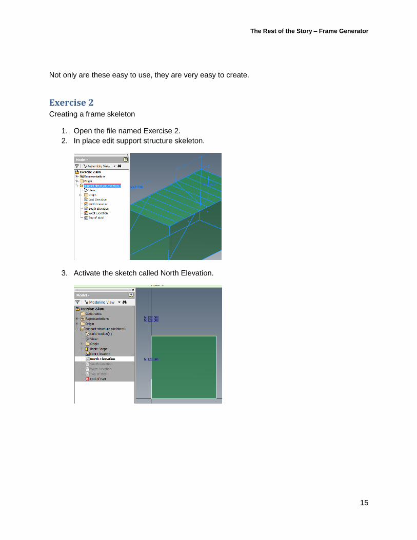
Not only are these easy to use, they are very easy to create.
Exercise 2 Creating a frame skeleton
1. Open the file named Exercise 2.
2. In place edit support structure skeleton.
3. Activate the sketch called North Elevation.
The Rest of the Story – Frame Generator
16
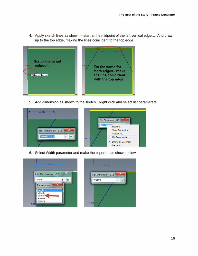
4. Apply sketch lines as shown – start at the midpoint of the left vertical edge…. And draw
up to the top edge, making the lines coincident to the top edge.
5. Add dimension as shown to the sketch. Right click and select list parameters.
6. Select Width parameter and make the equation as shown below.

The Rest of the Story – Frame Generator
17
7. Add a dimension to the other line. Make it match the other dimension you just created.
Your sketch should look like this. Finish the sketch.
8. Activate the sketch called South Elevation. Project these two lines to this sketch.

The Rest of the Story – Frame Generator
18
Your model should now look like this.
9. Select the Manage Tab – select iLogic Browser.

The Rest of the Story – Frame Generator
19
10. Select the forms tab on the iLogic dialog. Right click in the open space and select add
form.
11. In the forms dialog – the form name will default to form 1. Click on the name and
change it to FRAME DIMENSIONS
12. Drag and drop parameters length, width, and height to the right pane.

The Rest of the Story – Frame Generator
20
13. Select OK. FRAME DIMENSIONS now appears in the forms dialog. Select it.
14. You will see the dialog you just created. Change the length parameter to 420 and hit
enter. Note how the frame updates.

The Rest of the Story – Frame Generator
21
15. Save the file. Return to the top level.
16. Save the assembly. This ends the exercise.
Our Third Design Task Now that the skeletal model is created, it can be used to create frames as required. These
frames can be turned into assets. We need to populate the skeletal model with structural steel.

The Rest of the Story – Frame Generator
22
Exercise 3 We will add structural steel to an assembly.
1. Open Exercise 3.iam. You should see the following:
2. In the Design Tab, select Insert Frame Members.

The Rest of the Story – Frame Generator
23
3. We will add the beams to the top of the frame. We will use the W18x76. Set the
orientation and the rotation as shown below.
4. Select the sketch lines as shown below.

The Rest of the Story – Frame Generator
24
5. Select apply. Your model should look like this.
6. In the browser, double click on completed support structure skeleton to activate it in
place.
7. Under the manage tab, select iLogic Browser, select FRAME DIMENSIONS and open
the form. Change length from 384 to 420, change width from 192 to 220. Select done.
8. Return to top level.

The Rest of the Story – Frame Generator
25
9. Note the change in the frame. It should look like this.
Save the file. This completes the exercise.
Exercise 4 We will create an asset from the file we just created.

The Rest of the Story – Frame Generator
26
1. Open Exercise 4.iam.
2. In the browser, right click on completed support structure skeleton.ipt. Select suppress.
(This part is not needed for our asset)
3. Save the file. When prompted about the level of detail view, accept the default. Close
the assembly.
4. Select new, create a part file.

The Rest of the Story – Frame Generator
27
5. In the create ribbon, select Derive.
6. Select the maintain each as solid body option – this will allow others to re-create an
assembly at a later date if they’d like utilizing the make components command.
7. On the environments tab, select asset builder.
8. Select landing surface – rotate the model to a view that allows you to select the bottom
face of the column as shown below.
Select OK.

The Rest of the Story – Frame Generator
28
9. Save the file. Name it Support Frame.
10. Select Publish Asset. Allow it to be published in User Assets.
11. Select Finish Asset Builder. Close the file.
12. Start a new layout. Select the new frame asset you just created and place it anywhere
on the floor.
13. This completes the exercise.
Using Frame Generator to create hangers for a suspended conveyor You can also utilize Frame Generator to create hangers. Rather than field cutting and field
welding hangers into place, you can design them to be cut, manufactured and partially
assembled in the fab shop. This will allow a better, more accurate design – and drastically
speed the installation process.
There are two basic workflows that frame generator can support.
Many hangers required – standard elevations. For this workflow, you can make the
standard sizes of frames into assets. These can be placed into the layout, and a Bill Of
Material can be generated from this - it allows better, more accurate quotes and
proposals and also reduces waste.
Many hangers required – non-standard elevations. For this workflow, you DO NOT use
assets. Rather, you utilize a place component workflow – where the component
contains a skeletal model that can be populated in place with structural members.
These assemblies can then be detailed utilizing Inventor’s drawing creation capabilities.
A BOM can also be generated from the layout to get the required number of support
hanger frames that are required to complete the installation.
A few tips to be successful…
If you want to utilize Factory Design Suite’s standard components for your design, I
recommend copying these and publishing them to your own library. That way you can
change them to suit your company’s needs.
Create a sub-layout for your hangers and conveyor track. This makes it easy to create
BOMs for these components. You can also position these easily in their own sub-layout
– and allows this to be separate from the overall layout. This will pay dividends in
performance later on.

The Rest of the Story – Frame Generator
29
Other uses Frame generator is one of many tools within Inventor – the frames that are created can also be
validated with tools like Frame Analysis, available in Inventor Professional.
Inventor’s content center can also be leveraged to build accurate assemblies – and then build
accurate bills of materials.

The Rest of the Story – Frame Generator
30
Autodesk is interested in your feedback to help make Factory Design Suite a better product.
Feedback
Your product ideas – autodesk.com/fds_ideastation
Discussion groups – autodesk.com/discussiongroup-factorydesignsuite
Email Feedback – [email protected]
Beta Recruiting
FDS Beta – [email protected]