the response of a transformer differential relay to
TRANSCRIPT
The Response of a Transformer Differential Relay to Internal Faults While Influenced
by Geomagnetically Induced Currents
Andrew Mattei Baylor University/Brazos Electric Power Cooperative, Inc.
Derrick Haas and Jared Candelaria Schweitzer Engineering Laboratories, Inc.
Dr. W. Mack Grady Baylor University
Presented at the 74th Annual Conference for Protective Relay Engineers
Virtual Format March 22–25, 2021
Previously presented at the 47th Annual Western Protective Relay Conference, October 2020
Previous revised editions released September 2020 and October 2020
Original edition released September 2020
1
The Response of a Transformer Differential Relay to Internal Faults While Influenced by
Geomagnetically Induced Currents Andrew Mattei, Baylor University/Brazos Electric Power Cooperative, Inc.
Derrick Haas and Jared Candelaria, Schweitzer Engineering Laboratories, Inc. Dr. W. Mack Grady, Baylor University
Abstract—When influenced by quasi-dc ground currents, the magnetization characteristics of wye-connected transformers produce second harmonics that may approach or surpass second-harmonic levels commonly experienced during transformer inrush events. Transformer protection typically incorporates harmonic blocking and/or harmonic restraint to prevent the relay from operating during these inrush events. Newer relays also use waveshape recognition.
In this paper, we discuss a saturable transformer model simulation composed to create a matrix of tests that varied the magnitude of transformer internal fault current and the magnitude of quasi-dc ground current. We applied test currents on two transformer differential relay designs. One set of test currents was to validate that the relays remain secure for geomagnetically induced current (GIC) saturation, and the other to compare how the relays perform for internal faults with varying amounts of fault resistance and increasing levels of GIC. We explore cross-harmonic blocking and harmonic restraint as variables and evaluate the relationship of the pickup levels for the operate/restraint curve. We include recommendations for possible mitigation techniques.
I. INTRODUCTION
A. Overview of GIC and Ground Current Induced by HEMP Geomagnetic storms and the geomagnetically induced
currents (GICs) they produce are gaining attention. Some researchers believe they could cause or contribute to a large-scale outage. Specific attention to GIC has continually increased since the March 1989 power outage in the northeast United States and Canada, where GIC was determined to be a significant cause [1].
The physics and nature of GIC are well-documented in several sources, but [1] includes a very clear explanation. For brevity’s sake, we do not review the background on the causes of GIC or its quasi-dc characteristics, but rather refer to [1].
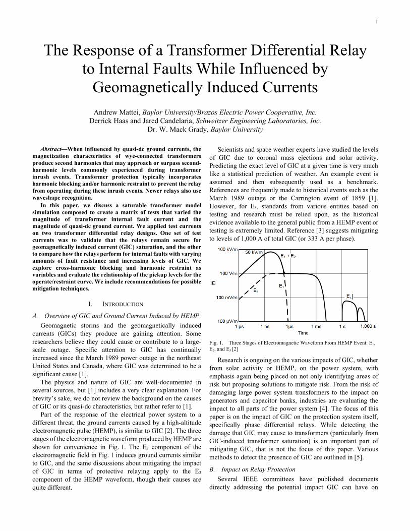
Part of the response of the electrical power system to a different threat, the ground currents caused by a high-altitude electromagnetic pulse (HEMP), is similar to GIC [2]. The three stages of the electromagnetic waveform produced by HEMP are shown for convenience in Fig. 1. The E3 component of the electromagnetic field in Fig. 1 induces ground currents similar to GIC, and the same discussions about mitigating the impact of GIC in terms of protective relaying apply to the E3 component of the HEMP waveform, though their causes are quite different.
Scientists and space weather experts have studied the levels of GIC due to coronal mass ejections and solar activity. Predicting the exact level of GIC at a given time is very much like a statistical prediction of weather. An example event is assumed and then subsequently used as a benchmark. References are frequently made to historical events such as the March 1989 outage or the Carrington event of 1859 [1]. However, for E3, standards from various entities based on testing and research must be relied upon, as the historical evidence available to the general public from a HEMP event or testing is extremely limited. Reference [3] suggests mitigating to levels of 1,000 A of total GIC (or 333 A per phase).
Fig. 1. Three Stages of Electromagnetic Waveform From HEMP Event: E1, E2, and E3 [2]
Research is ongoing on the various impacts of GIC, whether from solar activity or HEMP, on the power system, with emphasis again being placed on not only identifying areas of risk but proposing solutions to mitigate risk. From the risk of damaging large power system transformers to the impact on generators and capacitor banks, industries are evaluating the impact to all parts of the power system [4]. The focus of this paper is on the impact of GIC on the protection system itself, specifically phase differential relays. While detecting the damage that GIC may cause to transformers (particularly from GIC-induced transformer saturation) is an important part of mitigating GIC, that is not the focus of this paper. Various methods to detect the presence of GIC are outlined in [5].
B. Impact on Relay Protection Several IEEE committees have published documents
directly addressing the potential impact GIC can have on
2
protective relays [6] [7] [8]. The following are the primary risks they have focused on:
• Avoiding undesired relay operations during periods of high GIC
• Ensuring dependable and sensitive relay operation for actual faults that occur on the power system during periods of high GIC
References [6], [7], and [8] outline the impact to various types of protective relays, from overcurrent and ground distance to very specific capacitor relaying applications. In addition, [9] documents the impact of GIC on the response of current transformers (CTs), specifically the impact of GIC on CT saturation. This paper solely focuses on the impact of GIC on transformer differential relaying, specifically the phase differential elements. We did not include the impact of CT saturation in our model.
C. Transformer Protection and Transformer Differential Elements
For large transformers, several types of protection are often applied. For speed, selectivity, and sensitivity, phase differential protection (87) is applied for phase faults and, in some cases, for ground faults as well, particularly in solidly grounded systems where dedicated ground fault protection is often not applied. Because of the 87 element’s broad use, and very specific concerns about the response of the 87 element during periods of high GIC, we focus on this element in particular.
Traditionally, phase fault protection has involved only the phase differential and overcurrent elements. However, with modern microprocessor-based relays, more sensitive detection of phase faults and even detection of turn-to-turn faults is possible using a negative-sequence differential element (87Q) [10]. We evaluate the 87Q element as well in our testing and analysis.
There are other elements present, particularly for more sensitive detection of ground faults or turn-to-ground faults. These include the ground differential element (87G) or, alternatively, restricted earth fault (REF) schemes. Since the focus of our investigation is phase fault detection, and since some utilities still rely on the phase differential element for protection of ground faults, we did not evaluate the performance of these ground protection schemes in this paper. In addition, sudden pressure or Buchholz relays are often applied to detect internal transformer faults where the fault currents are difficult to detect with traditional phase differential elements.
The two relays analyzed in this paper are microprocessor-based relays of varying vintage, both with phase 87 elements using the adaptive slope characteristic described in [11].
The phase differential elements in these relays use (1) and (2) to calculate operate and restraint current, shown for just A-phase, respectively.
mIOPA IAmCFC= ∑ (1)
mIRTA IAmCFC= ∑ (2)
where: IOPA is the A-phase operate current per unit. IAmCFC is the A-phase filtered, compensated current per unit. m is the specific current restraint on the relay, labeled S, T, U, W, and X.
The method of calculating restraint current in (2) is referred to as an average or weighted average restraint [12]. The 87Q element uses a single-slope characteristic with a slightly different method of calculating restraint current. Equations (3), (4), and (5) outline how the 87Q element in both relays calculates negative-sequence, operate, and restraint current.
2
IAmCFC3I2mC • IBmCFC1 a a
ICmCFC
=
(3)
mIOP87Q 3I2mC= ∑ (4)
( )mIRT87Q max 3I2mC= (5)
where: a = 1∠120°. IAmCFC is the A-phase filtered, compensated current per unit. IBmCFC is the B-phase filtered, compensated current per unit. ICmCFC is the C-phase filtered, compensated current per unit.
For clarity, the older microprocessor-based relay is referred to as Relay 1. The newer microprocessor-based relay with additional algorithms and enhancements is referred to as Relay 2.
Both microprocessor-based relays have several methods to restrain incorrect tripping during inrush conditions. Both had the traditional methods of harmonic blocking and harmonic restraint applied. Relay 2 has an additional method of inrush restraint known as waveshape recognition that does not rely on harmonics. A comparison of these inrush restraint techniques is included in Section III.
II. MODEL USED FOR SIMULATION Core construction influences the susceptibility of a
transformer to saturation during the quasi-dc currents that occur with a GIC event. Single-phase, five-limb, and shell-form transformers provide low-reluctance return paths to the magnetic flux and permit more rapid core saturation than the higher-reluctance path present in three-limb core-form transformers [13].
A laboratory test bench was constructed using six single-phase wye-wye-connected transformers. In the test region of the circuit, the secondary winding of the first set of three transformers was connected to the primary winding of the second set of three transformers, with a balanced resistive load on the secondary side of the second set. Within the loop formed
3
by this connection, a switched battery-based dc source was placed in the neutral. When the switch was closed, the dc current saturated the transformers, and a GIC-like harmonic response was observed.
Data from the actual current waveforms collected from this laboratory test bench were used to create COMTRADE test files. These waveforms were used to evaluate the response of different types of relays to GIC-induced harmonic distortion [14]. To evaluate the response of the transformer differential relay to varying levels of GICs and different fault magnitudes and locations, a software model was necessary to generate test files. Open- and short-circuit tests were performed on these benchtop transformers, and a saturable transformer model of this laboratory test bench was created in Alternative Transients Program-Electromagnetic Transients Program (ATP-EMTP).
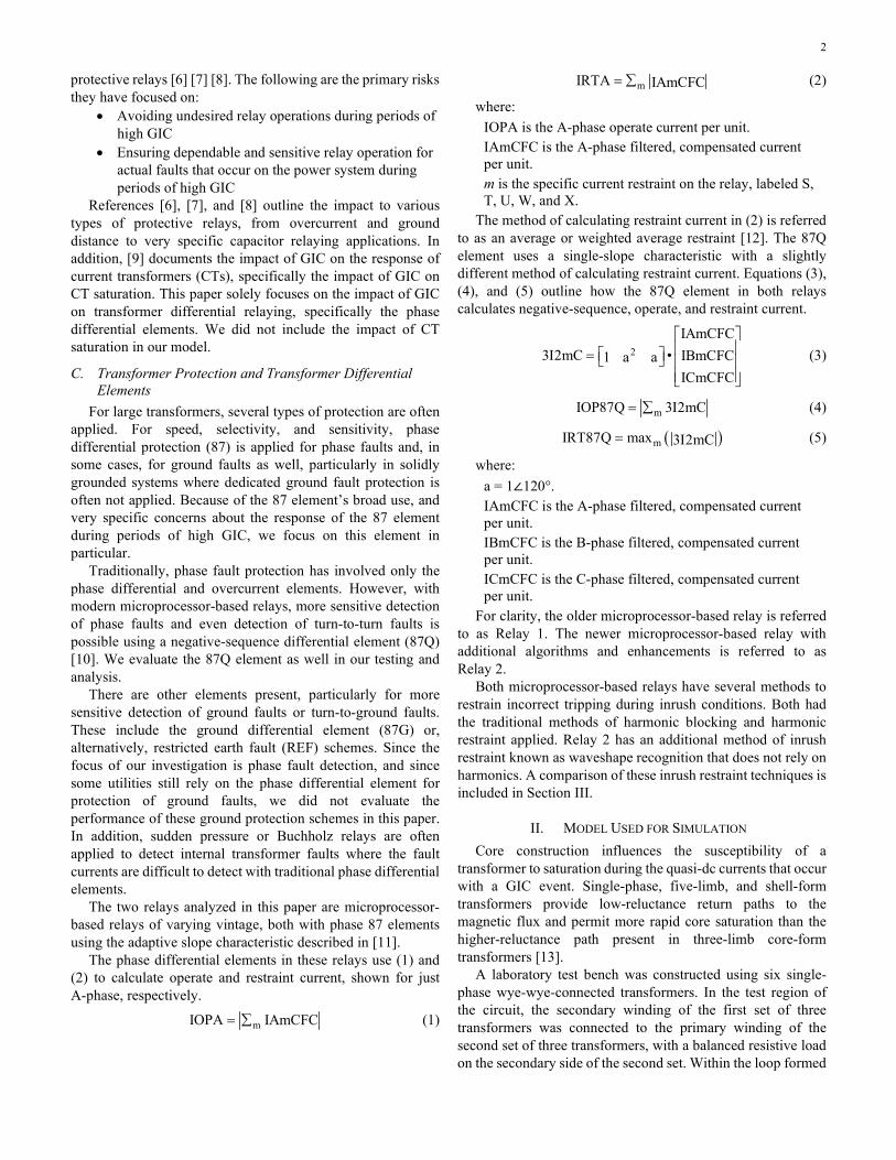
The saturable transformer model in ATP-EMTP provided a response that was similar to the test bench data under dc injection. This allowed the placement of a variety of faults both internal and external to the differential zone of protection. Faults were placed in the following locations with varying GIC levels and resistance values, with the locations noted in Fig. 2:
• Internal transformer primary phase-to-ground (F1) • Internal transformer primary phase-to-phase (F1) • Internal transformer secondary phase-to-ground (F2) • Internal transformer secondary phase-to-phase (F2) • External secondary phase-to-ground (F3) • External secondary phase-to-phase (F3)
Fig. 2. One-Line Diagram With Fault Locations
Other protective elements, such as sudden pressure protection and REF, are commonly used schemes within transformer protection but are not considered here because of the focus on the differential element.
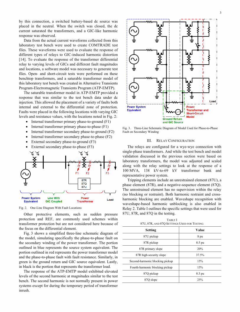
Fig. 3 shows a simplified three-line schematic diagram of the model, simulating specifically the phase-to-phase fault on the secondary winding of the power transformer. The portion outlined in blue represents the source system equivalent. The portion outlined in red represents the power transformer model and the phase-to-phase fault with fault resistance. Similarly, in green is the ground return and GIC source equivalent. Lastly, in black is the portion that represents the transformer load.
The response of the ATP-EMTP model exhibited elevated levels of the second harmonic at magnitudes similar to the test bench. The second harmonic is not normally present in power systems except for during the temporary period of transformer inrush.
Fig. 3. Three-Line Schematic Diagram of Model Used for Phase-to-Phase Fault on Secondary Winding
III. RELAY CONFIGURATION The relays are configured for a wye-wye connection with
single-phase transformers. And while the test bench and model validation discussed in the previous section were based on laboratory transformers, the model was adjusted and scaled along with the relay settings to look at the response of a 100 MVA, 138 kV-to-69 kV transformer bank and representative power system.
Tripping elements include an unrestrained element (87U), a phase element (87R), and a negative-sequence element (87Q). The unrestrained element has no supervision within the relay (no blocking or restraint). Both harmonic restraint and cross-harmonic blocking are enabled. Waveshape recognition with waveshape-based harmonic unblocking is also enabled in Relay 2. Table I outlines the specific settings that were used for 87U, 87R, and 87Q in the testing.
TABLE I 87U, 87R, AND 87Q SETTINGS USED FOR TESTING
Setting Value
87U pickup 8 pu
87R pickup 0.5 pu
87R primary slope 20%
87R high-security slope 37.5%
Second-harmonic blocking pickup 15%
Fourth-harmonic blocking pickup 15%
87Q pickup 0.3 pu
87Q slope 25%
4
A. Harmonic Restraint and Harmonic Blocking Harmonic restraint and harmonic blocking are commonly
used to prevent the transformer protection system from tripping due to asymmetrical currents present during transformer energization current inrush. In general, the differential protection system is based on the ratio of operate current to restraint current, with operate representing the current unbalance and restraint representing the balanced current. For harmonic restraint, the harmonic magnitudes are extracted from the unfiltered differential current magnitude and used to increase the tripping threshold. This additional restraint current added to the calculation provides security against tripping during an event (e.g., energization inrush) that causes the transformer to create harmonics.
Harmonic blocking uses the calculated percentage of harmonics in the operate current and compares it to the preset pickup value. If the calculated percentage exceeds the setting threshold, the relay blocks tripping for that differential element. Cross-harmonic blocking provides an additional level of security in that it restrains the relay if any of the three phases are above the harmonic blocking set-point threshold. It is commonly recommended to enable harmonic restraint, harmonic blocking, and cross-harmonic blocking as a set, so this combination is widely used.
B. Waveshape Recognition Waveshape recognition is a time-domain protection
algorithm that performs calculations based on sampled data rather than traditional phasor calculations. The theory, logic, and performance of waveshape recognition are outlined in [15].
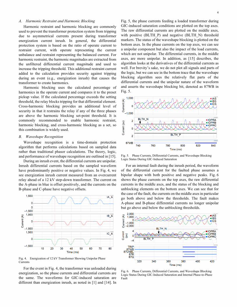
During an inrush event, the differential currents are unipolar. Inrush differential currents based on the sampled waveform have predominantly positive or negative values. In Fig. 4, we see energization inrush current measured from an overcurrent relay ahead of a 12 kV step-down transformer. The current on the A-phase in blue is offset positively, and the currents on the B-phase and C-phase have negative offsets.
Fig. 4. Energization of 12 kV Transformer Showing Unipolar Phase Currents
For the event in Fig. 4, the transformer was unloaded during energization, so the phase currents and differential currents are the same. The waveforms for GIC-induced saturation are different than energization inrush, as noted in [1] and [14]. In
Fig. 5, the phase currents feeding a loaded transformer during GIC-induced saturation conditions are plotted on the top axes. The raw differential currents are plotted on the middle axes, with positive (BLTH_P) and negative (BLTH_N) threshold markers. The status of the waveshape blocking is plotted on the bottom axes. In the phase currents on the top axes, we can see a unipolar component but also the impact of the load currents, which are not unipolar. The differential currents, in the middle axes, are more unipolar. In addition, as [15] describes, the algorithm looks at the derivatives of the differential currents as well. For brevity’s sake, we do not plot all signals and parts of the logic, but we can see in the bottom trace that the waveshape blocking algorithm sees the relatively flat parts of the differential currents and the unipolar nature of the waveform and asserts the waveshape blocking bit, denoted as 87WB in Fig. 5.
Fig. 5. Phase Currents, Differential Currents, and Waveshape Blocking Logic Status During GIC-Induced Saturation
For an internal fault during the inrush period, the waveform of the differential current for the faulted phase assumes a bipolar shape with both positive and negative peaks. Fig. 6 shows the phase currents on the top axes, the raw differential currents in the middle axes, and the status of the blocking and unblocking elements on the bottom axes. We can see that for the case of the fault, the currents on the middle axes in particular go both above and below the thresholds. The fault makes A-phase and B-phase differential currents no longer unipolar but go above and below the unblocking thresholds.
Fig. 6. Phase Currents, Differential Currents, and Waveshape Blocking Logic Status During GIC-Induced Saturation and Internal Phase-to-Phase Fault
5
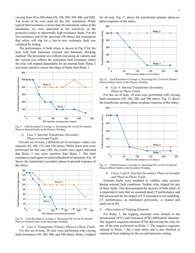
The waveshape unblocking logic is also described in [15]. A simplified version of a critical portion of the unblocking logic is shown in Fig. 7. We highlight the bipolar overcurrent detector that essentially looks for current both above and below a positive and negative threshold, respectively, within a certain time frame. The additional portions of the unblocking logic are discussed in [15], namely the sudden change in differential current detection.
Fig. 7. Simplified Unblocking Logic Showing Bipolar Overcurrent Elements
Based on this principle of symmetry and with some additional security checks and a supervising timer, a bipolar unblocking element is available in the relay. This unblocking element removes cross-harmonic blocking, waveshape-based inrush blocking, and the harmonic magnitudes from the calculations for harmonic-restrained differential elements. For negative-sequence protection, cross-blocking and waveshape-based inrush blocking are canceled, and the negative-sequence delay timer is bypassed.
IV. TEST RESULTS The test concept was to build a series of tests for comparing
varying GIC levels with varying fault resistance values. For test Cases 1–6 in this section, we evaluate and compare two relay designs: Relay 1 with harmonic restraint and cross-harmonic blocking, and Relay 2 with waveshape recognition combined with harmonic restraint and harmonic cross-blocking.
Fault resistance was varied according to the location of the fault. Our goal was to observe if there were thresholds in fault resistance at which the relays would or would not operate. As the relays were tested, an operation or no operation was noted, as well as the first tripping element from the sequential events recorder (SER) report.
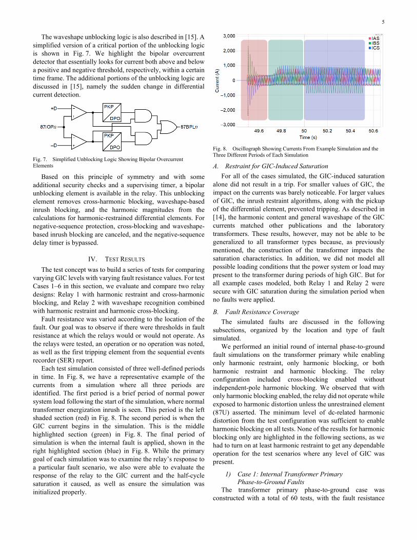
Each test simulation consisted of three well-defined periods in time. In Fig. 8, we have a representative example of the currents from a simulation where all three periods are identified. The first period is a brief period of normal power system load following the start of the simulation, where normal transformer energization inrush is seen. This period is the left shaded section (red) in Fig. 8. The second period is when the GIC current begins in the simulation. This is the middle highlighted section (green) in Fig. 8. The final period of simulation is when the internal fault is applied, shown in the right highlighted section (blue) in Fig. 8. While the primary goal of each simulation was to examine the relay’s response to a particular fault scenario, we also were able to evaluate the response of the relay to the GIC current and the half-cycle saturation it caused, as well as ensure the simulation was initialized properly.
Fig. 8. Oscillograph Showing Currents From Example Simulation and the Three Different Periods of Each Simulation
A. Restraint for GIC-Induced Saturation For all of the cases simulated, the GIC-induced saturation
alone did not result in a trip. For smaller values of GIC, the impact on the currents was barely noticeable. For larger values of GIC, the inrush restraint algorithms, along with the pickup of the differential element, prevented tripping. As described in [14], the harmonic content and general waveshape of the GIC currents matched other publications and the laboratory transformers. These results, however, may not be able to be generalized to all transformer types because, as previously mentioned, the construction of the transformer impacts the saturation characteristics. In addition, we did not model all possible loading conditions that the power system or load may present to the transformer during periods of high GIC. But for all example cases modeled, both Relay 1 and Relay 2 were secure with GIC saturation during the simulation period when no faults were applied.
B. Fault Resistance Coverage The simulated faults are discussed in the following
subsections, organized by the location and type of fault simulated.
We performed an initial round of internal phase-to-ground fault simulations on the transformer primary while enabling only harmonic restraint, only harmonic blocking, or both harmonic restraint and harmonic blocking. The relay configuration included cross-blocking enabled without independent-pole harmonic blocking. We observed that with only harmonic blocking enabled, the relay did not operate while exposed to harmonic distortion unless the unrestrained element (87U) asserted. The minimum level of dc-related harmonic distortion from the test configuration was sufficient to enable harmonic blocking on all tests. None of the results for harmonic blocking only are highlighted in the following sections, as we had to turn on at least harmonic restraint to get any dependable operation for the test scenarios where any level of GIC was present.
1) Case 1: Internal Transformer Primary Phase-to-Ground Faults
The transformer primary phase-to-ground case was constructed with a total of 60 tests, with the fault resistance
6
varying from 50 to 500 ohms (50, 100, 200, 300, 400, and 500). Ten levels of dc were used for the GIC simulation. While typical fault resistance is lower than the maximum values in the simulation, we were interested in the sensitivity of the protective relays to abnormally high-resistance faults. For the low-resistance end of the spectrum (50 ohms), the assumption that relays will trip for a low-to-zero resistance fault was validated by testing.
The performance of both relays is shown in Fig. 9 for the tests with both harmonic restraint and harmonic blocking enabled. The horizontal axis reflects increasing dc current, and the vertical axis reflects the maximum fault resistance where the relay still tripped dependably for an internal fault. Relay 2 was more sensitive across the range of faults than Relay 1.
Fig. 9. Fault Resistance Coverage vs. Increasing GIC Levels for Internal Phase-to-Ground Faults on the Primary Winding
2) Case 2: Internal Transformer Secondary Phase-to-Ground Faults
For this set of tests, a different set of resistance values was selected (50, 100, 125, and 150 ohms). While fewer tests were performed for this case (40), the results once again indicated that Relay 2 was more sensitive than Relay 1. The fault resistances used again revealed a threshold of operation. Fig. 10 shows the transformer secondary phase-to-ground response of the relays.
Fig. 10. Fault Resistance Coverage vs. Increasing GIC Levels for Internal Phase-to-Ground Faults on the Secondary Winding
3) Case 3: Transformer Primary Phase-to-Phase Faults For this set of tests, 20 tests were performed with varying
fault resistances (50, 300, 400, and 500 ohms). Relay 2 tripped
for all tests. Fig. 11 shows the transformer primary phase-to-phase response of the relays.
Fig. 11. Fault Resistance Coverage vs. Increasing GIC Levels for Internal Phase-to-Phase Faults on the Primary Winding
4) Case 4: Internal Transformer Secondary Phase-to-Phase Faults
For this set of tests, 20 tests were performed with varying fault resistances (50, 100, 200, and 300 ohms). Fig. 12 shows the transformer primary phase-to-phase response of the relays.
Fig. 12. Fault Resistance Coverage vs. Increasing GIC Levels for Internal Phase-to-Phase Faults on the Secondary Winding
5) Cases 5 and 6: External Secondary Phase-to-Ground and Phase-to-Phase Faults
External faults were modeled to validate relay security during external fault conditions. Neither relay tripped for any of these faults. This demonstrated the security of both relays. It is important to note that we assumed ideal CT performance and did not account for the impact of CT saturation in our modeling. CT performance, as mentioned previously, is treated and analyzed in [9].
C. Observation of Tripping Elements For Relay 1, the tripping elements were limited to the
unrestrained (87U) and restrained (87R) differential elements. The negative-sequence element (87Q) did not trip the relay for any of the tests performed on Relay 1. The negative-sequence element in Relay 1 has a time delay and is also blocked or restrained from tripping by the second-harmonic setting.
7
For Relay 2, there were numerous instances of simultaneous or very near tripping of all three elements (87U, 87Q, and 87R). It was common to see 87Q and 87U with the same time stamp in the SER log, with 87R trailing these asserted elements by 2 milliseconds. Waveshape unblocking was key to the fast response and is briefly described in the next section.
D. Importance of Unblocking Logic and Unrestrained Elements
During a strong geomagnetic disturbance, elevated harmonics assert harmonic blocking while the second-harmonic currents are added to the differential restraint. This desensitizes the relay to low-magnitude internal faults.
An additional enhancement to the unrestrained differential element operated the relay during high-current faults. The unrestrained element may operate as usual on the fundamental current, but a bipolar element and a scaled Sampled Values-based element are available. In this testing, the waveshape-based bipolar logic operated more quickly than the standard differential elements.
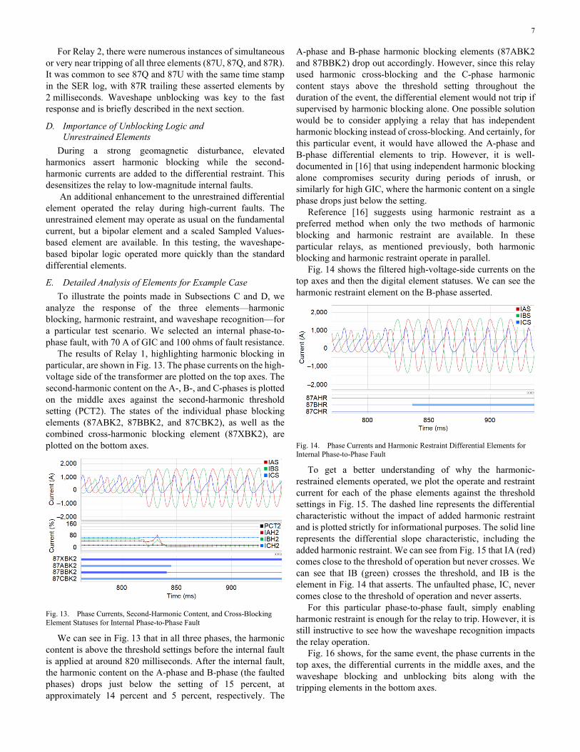
E. Detailed Analysis of Elements for Example Case To illustrate the points made in Subsections C and D, we
analyze the response of the three elements—harmonic blocking, harmonic restraint, and waveshape recognition—for a particular test scenario. We selected an internal phase-to-phase fault, with 70 A of GIC and 100 ohms of fault resistance.
The results of Relay 1, highlighting harmonic blocking in particular, are shown in Fig. 13. The phase currents on the high-voltage side of the transformer are plotted on the top axes. The second-harmonic content on the A-, B-, and C-phases is plotted on the middle axes against the second-harmonic threshold setting (PCT2). The states of the individual phase blocking elements (87ABK2, 87BBK2, and 87CBK2), as well as the combined cross-harmonic blocking element (87XBK2), are plotted on the bottom axes.
Fig. 13. Phase Currents, Second-Harmonic Content, and Cross-Blocking Element Statuses for Internal Phase-to-Phase Fault
We can see in Fig. 13 that in all three phases, the harmonic content is above the threshold settings before the internal fault is applied at around 820 milliseconds. After the internal fault, the harmonic content on the A-phase and B-phase (the faulted phases) drops just below the setting of 15 percent, at approximately 14 percent and 5 percent, respectively. The
A-phase and B-phase harmonic blocking elements (87ABK2 and 87BBK2) drop out accordingly. However, since this relay used harmonic cross-blocking and the C-phase harmonic content stays above the threshold setting throughout the duration of the event, the differential element would not trip if supervised by harmonic blocking alone. One possible solution would be to consider applying a relay that has independent harmonic blocking instead of cross-blocking. And certainly, for this particular event, it would have allowed the A-phase and B-phase differential elements to trip. However, it is well-documented in [16] that using independent harmonic blocking alone compromises security during periods of inrush, or similarly for high GIC, where the harmonic content on a single phase drops just below the setting.
Reference [16] suggests using harmonic restraint as a preferred method when only the two methods of harmonic blocking and harmonic restraint are available. In these particular relays, as mentioned previously, both harmonic blocking and harmonic restraint operate in parallel.
Fig. 14 shows the filtered high-voltage-side currents on the top axes and then the digital element statuses. We can see the harmonic restraint element on the B-phase asserted.
Fig. 14. Phase Currents and Harmonic Restraint Differential Elements for Internal Phase-to-Phase Fault
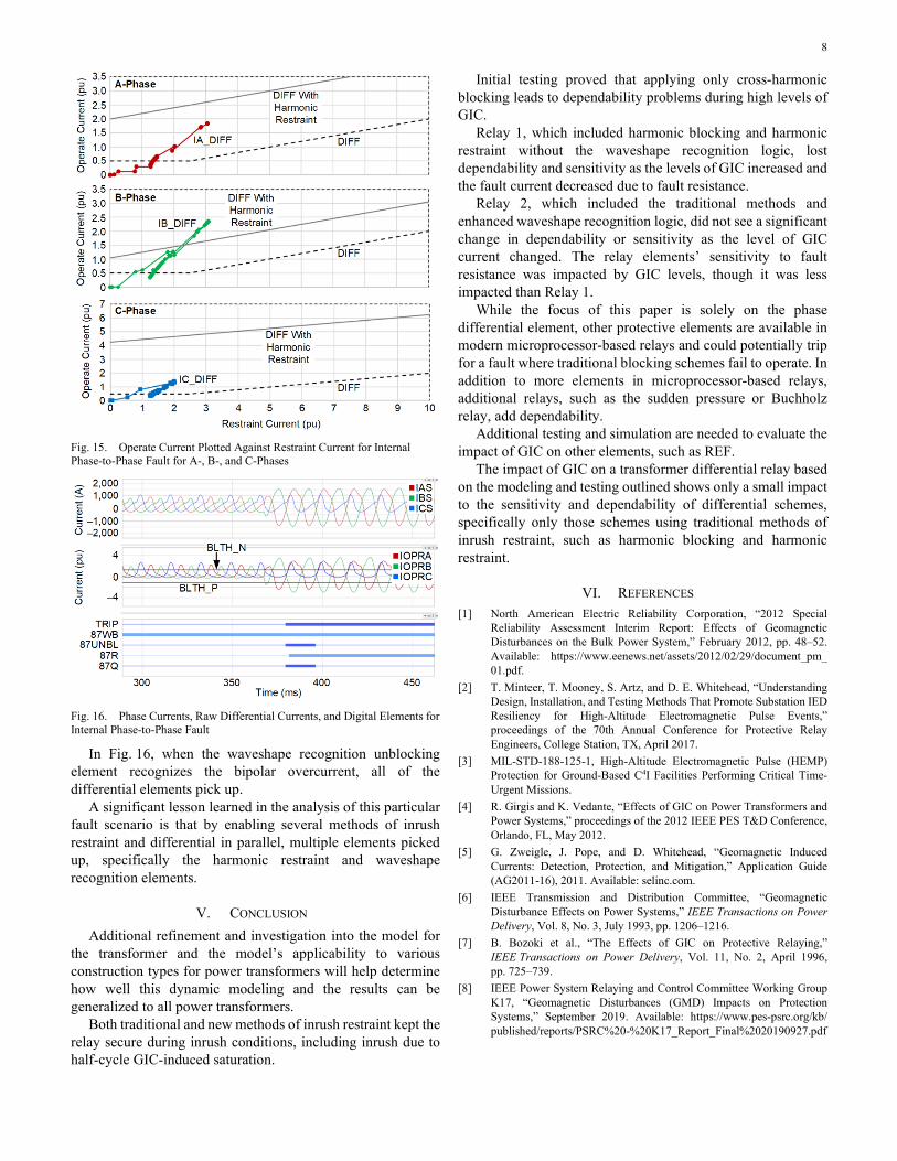
To get a better understanding of why the harmonic-restrained elements operated, we plot the operate and restraint current for each of the phase elements against the threshold settings in Fig. 15. The dashed line represents the differential characteristic without the impact of added harmonic restraint and is plotted strictly for informational purposes. The solid line represents the differential slope characteristic, including the added harmonic restraint. We can see from Fig. 15 that IA (red) comes close to the threshold of operation but never crosses. We can see that IB (green) crosses the threshold, and IB is the element in Fig. 14 that asserts. The unfaulted phase, IC, never comes close to the threshold of operation and never asserts.
For this particular phase-to-phase fault, simply enabling harmonic restraint is enough for the relay to trip. However, it is still instructive to see how the waveshape recognition impacts the relay operation.
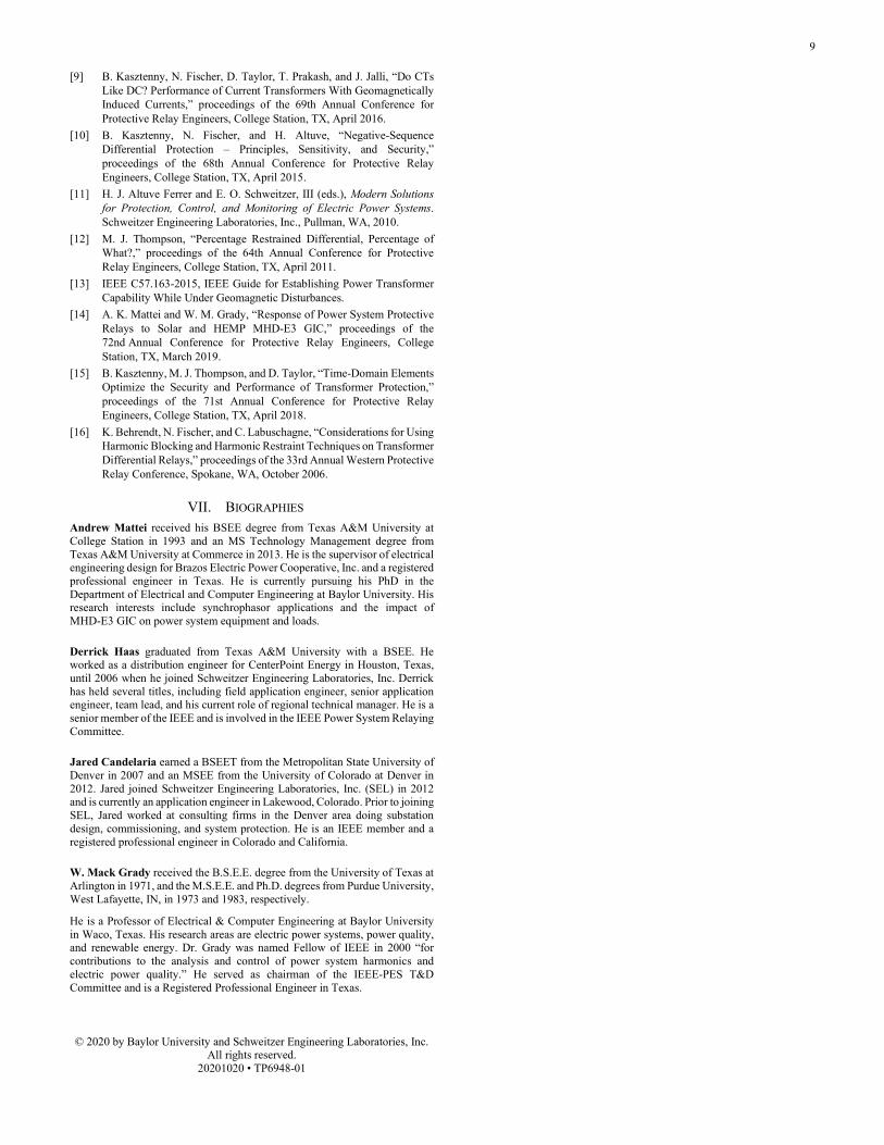
Fig. 16 shows, for the same event, the phase currents in the top axes, the differential currents in the middle axes, and the waveshape blocking and unblocking bits along with the tripping elements in the bottom axes.
8
Fig. 15. Operate Current Plotted Against Restraint Current for Internal Phase-to-Phase Fault for A-, B-, and C-Phases
Fig. 16. Phase Currents, Raw Differential Currents, and Digital Elements for Internal Phase-to-Phase Fault
In Fig. 16, when the waveshape recognition unblocking element recognizes the bipolar overcurrent, all of the differential elements pick up.
A significant lesson learned in the analysis of this particular fault scenario is that by enabling several methods of inrush restraint and differential in parallel, multiple elements picked up, specifically the harmonic restraint and waveshape recognition elements.
V. CONCLUSION Additional refinement and investigation into the model for
the transformer and the model’s applicability to various construction types for power transformers will help determine how well this dynamic modeling and the results can be generalized to all power transformers.
Both traditional and new methods of inrush restraint kept the relay secure during inrush conditions, including inrush due to half-cycle GIC-induced saturation.
Initial testing proved that applying only cross-harmonic blocking leads to dependability problems during high levels of GIC.
Relay 1, which included harmonic blocking and harmonic restraint without the waveshape recognition logic, lost dependability and sensitivity as the levels of GIC increased and the fault current decreased due to fault resistance.
Relay 2, which included the traditional methods and enhanced waveshape recognition logic, did not see a significant change in dependability or sensitivity as the level of GIC current changed. The relay elements’ sensitivity to fault resistance was impacted by GIC levels, though it was less impacted than Relay 1.
While the focus of this paper is solely on the phase differential element, other protective elements are available in modern microprocessor-based relays and could potentially trip for a fault where traditional blocking schemes fail to operate. In addition to more elements in microprocessor-based relays, additional relays, such as the sudden pressure or Buchholz relay, add dependability.
Additional testing and simulation are needed to evaluate the impact of GIC on other elements, such as REF.
The impact of GIC on a transformer differential relay based on the modeling and testing outlined shows only a small impact to the sensitivity and dependability of differential schemes, specifically only those schemes using traditional methods of inrush restraint, such as harmonic blocking and harmonic restraint.
VI. REFERENCES [1] North American Electric Reliability Corporation, “2012 Special
Reliability Assessment Interim Report: Effects of Geomagnetic Disturbances on the Bulk Power System,” February 2012, pp. 48–52. Available: https://www.eenews.net/assets/2012/02/29/document_pm_ 01.pdf.
[2] T. Minteer, T. Mooney, S. Artz, and D. E. Whitehead, “Understanding Design, Installation, and Testing Methods That Promote Substation IED Resiliency for High-Altitude Electromagnetic Pulse Events,” proceedings of the 70th Annual Conference for Protective Relay Engineers, College Station, TX, April 2017.
[3] MIL-STD-188-125-1, High-Altitude Electromagnetic Pulse (HEMP) Protection for Ground-Based C4I Facilities Performing Critical Time-Urgent Missions.
[4] R. Girgis and K. Vedante, “Effects of GIC on Power Transformers and Power Systems,” proceedings of the 2012 IEEE PES T&D Conference, Orlando, FL, May 2012.
[5] G. Zweigle, J. Pope, and D. Whitehead, “Geomagnetic Induced Currents: Detection, Protection, and Mitigation,” Application Guide (AG2011-16), 2011. Available: selinc.com.
[6] IEEE Transmission and Distribution Committee, “Geomagnetic Disturbance Effects on Power Systems,” IEEE Transactions on Power Delivery, Vol. 8, No. 3, July 1993, pp. 1206–1216.
[7] B. Bozoki et al., “The Effects of GIC on Protective Relaying,” IEEE Transactions on Power Delivery, Vol. 11, No. 2, April 1996, pp. 725–739.
[8] IEEE Power System Relaying and Control Committee Working Group K17, “Geomagnetic Disturbances (GMD) Impacts on Protection Systems,” September 2019. Available: https://www.pes-psrc.org/kb/ published/reports/PSRC%20-%20K17_Report_Final%2020190927.pdf
9
[9] B. Kasztenny, N. Fischer, D. Taylor, T. Prakash, and J. Jalli, “Do CTs Like DC? Performance of Current Transformers With Geomagnetically Induced Currents,” proceedings of the 69th Annual Conference for Protective Relay Engineers, College Station, TX, April 2016.
[10] B. Kasztenny, N. Fischer, and H. Altuve, “Negative-Sequence Differential Protection – Principles, Sensitivity, and Security,” proceedings of the 68th Annual Conference for Protective Relay Engineers, College Station, TX, April 2015.
[11] H. J. Altuve Ferrer and E. O. Schweitzer, III (eds.), Modern Solutions for Protection, Control, and Monitoring of Electric Power Systems. Schweitzer Engineering Laboratories, Inc., Pullman, WA, 2010.
[12] M. J. Thompson, “Percentage Restrained Differential, Percentage of What?,” proceedings of the 64th Annual Conference for Protective Relay Engineers, College Station, TX, April 2011.
[13] IEEE C57.163-2015, IEEE Guide for Establishing Power Transformer Capability While Under Geomagnetic Disturbances.
[14] A. K. Mattei and W. M. Grady, “Response of Power System Protective Relays to Solar and HEMP MHD-E3 GIC,” proceedings of the 72nd Annual Conference for Protective Relay Engineers, College Station, TX, March 2019.
[15] B. Kasztenny, M. J. Thompson, and D. Taylor, “Time-Domain Elements Optimize the Security and Performance of Transformer Protection,” proceedings of the 71st Annual Conference for Protective Relay Engineers, College Station, TX, April 2018.
[16] K. Behrendt, N. Fischer, and C. Labuschagne, “Considerations for Using Harmonic Blocking and Harmonic Restraint Techniques on Transformer Differential Relays,” proceedings of the 33rd Annual Western Protective Relay Conference, Spokane, WA, October 2006.
VII. BIOGRAPHIES Andrew Mattei received his BSEE degree from Texas A&M University at College Station in 1993 and an MS Technology Management degree from Texas A&M University at Commerce in 2013. He is the supervisor of electrical engineering design for Brazos Electric Power Cooperative, Inc. and a registered professional engineer in Texas. He is currently pursuing his PhD in the Department of Electrical and Computer Engineering at Baylor University. His research interests include synchrophasor applications and the impact of MHD-E3 GIC on power system equipment and loads.
Derrick Haas graduated from Texas A&M University with a BSEE. He worked as a distribution engineer for CenterPoint Energy in Houston, Texas, until 2006 when he joined Schweitzer Engineering Laboratories, Inc. Derrick has held several titles, including field application engineer, senior application engineer, team lead, and his current role of regional technical manager. He is a senior member of the IEEE and is involved in the IEEE Power System Relaying Committee.
Jared Candelaria earned a BSEET from the Metropolitan State University of Denver in 2007 and an MSEE from the University of Colorado at Denver in 2012. Jared joined Schweitzer Engineering Laboratories, Inc. (SEL) in 2012 and is currently an application engineer in Lakewood, Colorado. Prior to joining SEL, Jared worked at consulting firms in the Denver area doing substation design, commissioning, and system protection. He is an IEEE member and a registered professional engineer in Colorado and California.
W. Mack Grady received the B.S.E.E. degree from the University of Texas at Arlington in 1971, and the M.S.E.E. and Ph.D. degrees from Purdue University, West Lafayette, IN, in 1973 and 1983, respectively.
He is a Professor of Electrical & Computer Engineering at Baylor University in Waco, Texas. His research areas are electric power systems, power quality, and renewable energy. Dr. Grady was named Fellow of IEEE in 2000 “for contributions to the analysis and control of power system harmonics and electric power quality.” He served as chairman of the IEEE-PES T&D Committee and is a Registered Professional Engineer in Texas.
© 2020 by Baylor University and Schweitzer Engineering Laboratories, Inc. All rights reserved.
20201020 • TP6948-01