the regulations in this part set forth the requirements to ... 18.pdfthe regulations in this part...
TRANSCRIPT

Sec. 18.1 Purpose.
The regulations in this part set forth the requirements to obtain MSHA: Approval of electrically operated machines and accessories
intended for use in gassy mines or tunnels, certification of components intended for use on or with approved machines, permission to modify the
design of an approved machine or certified component, acceptance of flame-resistant hoses and conveyor belts, sanction for use of
experimental machines and accessories in gassy mines or tunnels; also, procedures for applying for such approval, certification, acceptance for
listing.
[43 FR 12313, Mar. 24, 1978, as amended at 52 FR 17514, May 8, 1987; 57 FR 61223, Dec. 23, 1992]
Sec. 18.2 Definitions.
As used in this part--
Acceptance means written notification by MSHA that a hose or conveyor belt has met the applicable requirements of this part and will be listed by MSHA as acceptable flame-resistant auxiliary equipment.
Acceptance marking means an identifying marking indicating that the hose or conveyor belt has been accepted by MSHA for listing as flame
resistant. Accessory means associated electrical equipment, such as a
distribution or splice box, that is not an integral part of an approved (permissible) machine.
Assistant Secretary means the Assistant Secretary of Labor for Mine Safety and Health.
Afterburning means the combustion of a flammable mixture that is drawn into a machine compartment after an internal explosion in the
compartment. Applicant means an individual, partnership, company, corporation, organization, or association that designs, manufactures, assembles, or controls the assembly of an electrical machine or accessory and seeks approval, certification, or permit, or MSHA acceptance for listing of
flame-resistant hose or conveyor belt. Approval means a formal document issued by MSHA which states that a
completely assembled electrical machine or accessory has met the applicable requirements of this part and which authorizes the attachment
of an approval plate so indicating. Approval plate means a metal plate, the design of which meets MSHA's
requirements, for attachment to an approved machine or accessory, identifying it as permissible for use in gassy mines or tunnels.
[[Page 91]]
Branch circuit means an electrical circuit connected to the main circuit, the conductors of which are of smaller size than the main

circuit. Bureau means the U.S. Bureau of Mines.
Certification means a formal written notification, issued by MSHA, which states that an electrical component complies with the applicable
requirements of this part and, therefore, is suitable for incorporation in approved (permissible) equipment.
Certification label means a plate, label, or marking, the design of which meets MSHA's requirements, for attachment to a certified component
identifying the component as having met the MSHA's requirements for incorporation in a machine to be submitted for approval.
Component means an integral part of an electrical machine or accessory that is essential to the functioning of the machine or
accessory. Connection box (also known as conduit or terminal box) means an enclosure mounted on an electrical machine or accessory to facilitate wiring, without the use of external splices. (Such boxes may have a
joint common with an explosion-proof enclosure provided the adjoining surfaces conform to the requirements of subpart B of this part.) Cylindrical joint means a joint comprised of two contiguous,
concentric, cylindrical surfaces. Distribution box means an enclosure through which one or more
portable cables may be connected to a source of electrical energy, and which contains a short-circuit protective device for each outgoing
cable. Experimental equipment means any electrical machine or accessory that an applicant or MSHA may desire to operate experimentally for a
limited time in a gassy mine or tunnel. (For example, this might include a machine constructed at a mine, an imported machine, or a machine or
device designed and developed by MSHA.) Explosion-proof enclosure means an enclosure that complies with the
applicable design requirements in subpart B of this part and is so constructed that it will withstand internal explosions of methane-air
mixtures: (1) Without damage to or excessive distortion of its walls or cover(s), and (2) without ignition of surrounding methane-air mixtures
or discharge of flame from inside to outside the enclosure. Fire-resistant as applied to conveyor belts means belting that will
pass the flame tests hereafter specified. Flame-arresting path means two or more adjoining or adjacent
surfaces between which the escape of flame is prevented. Flame resistant as applied to cable, hose, and insultating materials
means material that will burn when held in a flame but will cease burning when the flame is removed.
Flammable mixture means a mixture of methane or natural gas and air that when ignited will propagate flame. Natural gas containing a high percentage of methane is a satisfactory substitute for pure methane in
most tests. Gassy mine means a coal mine classed as ``gassy'' by MESA or by the
State in which the mine is situated. Incendive arc or spark means an arc or spark releasing enough
electrical or thermal energy to ignite a flammable mixture of the most easily ignitable composition.
Intrinsically safe means incapable of releasing enough electrical or thermal energy under normal or abnormal conditions to cause ignition of a flammable mixture of methane or natural gas and air of the most easily
ignitable composition. MESA means the United States Department of the Interior, Mining
Enforcement and Safety Administration. Predecessor organization to MSHA, prior to March 9, 1978.
Mobile equipment means equipment that is self-propelled. MSHA means the United States Department of Labor, Mine Safety and
Health Administration.
Plane joint means two adjoining surfaces in parallel planes. Portable cable, or trailing cable means a flame-resistant, flexible
cable or cord through which electrical energy is transmitted to a permissible machine or accessory. (A portable cable is that portion of
the power-supply system between the last short-circuit protective device, acceptable to MSHA, in the system and the machine or accessory
to which it transmits electrical energy.) Portable equipment means equipment that may be moved frequently and
is constructed or mounted to facilitate such movement. Potted component means a component that is entirely embedded in a
solidified insulating material within an enclosure. Pressure piling means the development of abnormal pressure as a result of accelerated rate of burning of a gas-air mixture. (Frequently
caused by restricted configurations within enclosures.) Qualified representative means a person authorized by MSHA to
determine whether the applicable requirements of this part have been complied with in the original manufacture, rebuilding, or repairing of
equipment for which approval, certification, or a permit is sought. Splice box means a portable enclosure in which electrical conductors
may be joined. Step (rabbet) joint means a joint comprised of two adjoining
surfaces with a change(s) in direction between its inner and outer edges. (A step joint may be composed of a cylindrical portion and a
plane portion or of two or more plane portions.) Threaded joint means a joint consisting of a male- and a female-
threaded member, both of which are of the same type and gage.
An approval will be issued only for a complete electrical machine or accessory. Only components meeting the requirements of subpart B of this
part or those approved under part 7 of this chapter, unless they contain intrinsically safe circuits, shall be included in the assemblies.
[
Sec. 18.5 Equipment for which certification will be issued.
Certification will be issued for a component or subassembly suitable

to incorporate in an approved machine. Certification may be issued for such components as explosion-proof enclosures, battery trays, and
connectors.
Sec. 18.6 Applications.
(a)(1) Investigation leading to approval, certification, extension thereof, or acceptance of hose or conveyor belt, will be undertaken by
MSHA only pursuant to a written application accompanied by a check, bank draft, or money order, payable to the U.S. Mine Safety and Health
Administration to cover the fees. The application shall be accompanied by all necessary drawings, specifications, descriptions, and related
materials, as set out in this part.
[[Page 93]]
(2) Where the applicant for approval has used an independent testing laboratory under part 6 of this chapter to perform, in whole or in part, the necessary testing and evaluation for approval under this part, the applicant must provide to MSHA as part of the approval application: (i) Written evidence of the laboratory's independence and current
recognition by a laboratory accrediting organization; (ii) Complete technical explanation of how the product complies with
each requirement in the applicable MSHA product approval requirements; (iii) Identification of components or features of the product that
are critical to the safety of the product; and (iv) All documentation, including drawings and specifications, as
submitted to the independent laboratory by the applicant and as required by this part.
(3) An applicant may request testing and evaluation to non-MSHA product safety standards which have been determined by MSHA to be
equivalent, under Sec. 6.20 of this chapter, to MSHA's product approval requirements under this part.
(4) The application, all related documents, and all correspondence concerning it shall be addressed to the Approval and Certification Center, Rural Route <greek-i>1, Box 251, Industrial Park Road,
Triadelphia, WV 26059. (b) [Reserved]
(c) Applications for acceptance of a conveyor belt as fire resistant shall include the following information: Trade name of the conveyor
belt, thickness of covers, friction and skim coats, number of plies, type and weight of ply material, and designation of breaker strip or
floated ply. The applicant shall provide other description or specifications as may be subsequently required.
(d) Applications for acceptance of hose as flame resistant shall include the following information: Trade name of hose, identification of
materials used, including compound numbers, thickness of cover, thickness of tube, and number and weight of plies. The applicant shall
provide other description or specifications as may be subsequently

required. (e) Drawings, drawing lists, specifications, wiring diagram, and
descriptions shall be adequate in number and detail to identify fully the complete assembly, component parts, and subassemblies. Drawings
shall be titled, numbered, dated and shall show the latest revision. Each drawing shall include a warning statement that changes in design
must be authorized by MSHA before they are applied to approved equipment. When intrinsically safe circuits are incorporated in a
machine or accessory, the wiring diagram shall include a warning statement that any change(s) in the intrinsically safe circuitry or
components may result in an unsafe condition. The specifications shall include an assembly drawing(s) (see Figure 1 in Appendix II) showing the
overall dimensions of the machine and the identity of each component part which may be listed thereon or separately, as in a bill of material
(see Figure 2 in Appendix II). MSHA may accept photographs (minimum size 8<gr-thn-eq> x 10\1/2\<gr-thn-eq>) in lieu of assembly drawing(s).
Purchased parts shall be identified by the manufacturer's name, catalog number(s), and rating(s). In the case of standard hardware and miscellaneous parts, such as insulating pieces, size and kind of
material shall be specified. All drawings of component parts submitted to MSHA shall be identical to those used in the manufacture of the parts. Dimensions of parts designed to prevent the passage of flame
shall specify allowable tolerances. A notation ``Do Not Drill Through'' or equivalent should appear on drawings with the specifications for all
``blind'' holes. (f) MSHA reserves the right to require the applicant to furnish
supplementary drawings showing sections through complex flame-arresting paths, such as labyrinths used in conjunction with ball or roller
bearings, and also drawings containing dimensions not indicated on other drawings submitted to MSHA.
(g) The applicant may ship his equipment to MSHA for investigation at the time of filing his application and payment of the required fees.
Shipping charges shall be prepaid by the applicant. (h) For a complete investigation leading to approval or
certification the
[[Page 94]]
applicant shall furnish MSHA with the components necessary for inspection and testing. Expendable components shall be supplied by the applicant to permit continuous operation of the equipment while being
tested. If special tools are necessary to assemble or disassemble any component for inspection or test, the applicant shall furnish them with
the equipment to be tested. (i) For investigation of a hose or conveyor belt, the applicant
shall furnish samples as follows:
Hose--a sample having a minimum length of 2 feet; Conveyor belt--a sample of each type 8 inches long cut across the entire

width of the belt.
(j) The applicant shall submit a sample caution statement (see Figure 3 in Appendix II) specifying the conditions for maintaining
permissibility of the equipment. (k) The applicant shall submit a factory-inspection form (see Figure
4 in Appendix II) used to maintain quality control at the place of manufacture or assembly to insure that component parts are made and assembled in strict accordance with the drawings and specifications covering a design submitted to MSHA for approval or certification. (l) MSHA will accept an application for an approval, a letter of
certification, or an acceptance for listing of a product that is manufactured in a country other than the United States provided: (1) All
correspondence, specifications, lettering on drawings (metric-system dimensions acceptable), instructions, and related information are in
English; and (2) all other requirements of this part are met the same as for a domestic applicant.
[33 FR 4660, Mar. 19, 1968, as amended at 43 FR 12314, Mar. 24, 1978; 47
FR 14696, Apr. 6, 1982; 57 FR 61223, Dec. 23, 1992; 60 FR 33723, June 29, 1995; 60 FR 35693, July 11, 1995; 68 FR 36419, June 17, 2003]
Sec. 18.7 [Reserved]
Sec. 18.8 Date for conducting investigation and tests.
The date of receipt of an application will determine the order of precedence for investigation and testing. If an electrical machine
component or accessory fails to meet any of the requirements, it shall lose its order of precedence. If an application is submitted to resume
investigation and testing after correction of the cause of failure, it will be treated as a new application and the order of precedence for
investigation and testing will be so determined.
Sec. 18.9 Conduct of investigations and tests.
(a) Prior to the issuance of an approval, certification, or acceptance of a hose or conveyor belt, only MSHA personnel,
representative(s) of the applicant, and such other person(s) as may be mutually agreed upon may observe any part of the investigation or tests. The MSHA will hold as confidential and will not disclose principles or
patentable features; nor will it disclose to persons other than the applicant the results of tests, chemical analysis of materials or any details of the applicant's drawings, specifications, instructions, and
related material. (b) Unless notified to the contrary by MSHA, the applicant shall provide assistance in disassembling parts for inspection, preparing
parts for testing, and preparing equipment for return shipment. Explosion-proof enclosures shall be drilled and tapped for pipe
connections in accordance with instructions supplied by MSHA. (c) MSHA reserves the right to inspect a complete machine, component
part, or accessory at a place other than the Bureau's premises, such as the assembly plant or other location acceptable to MSHA, at the
applicant's expense. (d) Applicants shall be responsible for their representatives
present during tests and for observers admitted at their request and shall save the Government harmless in the event of damage to applicant's
property or injury to applicant's representatives or to observers admitted at their request.
[33 FR 4660, Mar. 19, 1968; 33 FR 6345, Apr. 26, 1968, as amended at 57
FR 61223, Dec. 23, 1992]
Sec. 18.10 Notice of approval or disapproval.
(a) Upon completing investigation of a complete assembly of an electrical machine or accessory, MSHA will issue to the applicant either
a written notice
[[Page 95]]
of approval or a written notice of disapproval, as the case may require. No informal notification of approval will be issued. If a notice of
disapproval is issued, it will be accompanied by details of the defects, with recommendations for possible correction. MSHA will not disclose,
except to the applicant, any information upon which a notice of disapproval has been issued.
(b) A formal notice of approval will be accompanied by a list of drawings, specifications, and related material, covering the details of design and construction of the equipment upon which the approval is
based. Applicants shall keep exact duplicates of the drawings, specifications, and descriptions that relate to equipment for which an
approval has been issued, and the drawings and specifications shall be adhered to exactly in production of the approved equipment.
(c) An applicant shall not advertise or otherwise represent his equipment as approved (permissible) until he has received MSHA's formal
notice of approval.
Sec. 18.11 Approval plate.
(a)(1) The notice of approval will be accompanied by a photograph of an approval plate, bearing the emblem of Mine Safety and Health
Administration, the name of the complete assembly, the name of the applicant, and spaces for the approval number, serial number, and the
type or model of machine. (2) An extension of approval will not affect the original approval
number except that the extension number shall be added to the original approval number on the approval plate. (Example: Original approval No.
2G-3000; seventh extension No. 2G-3000-7.) (b) The applicant shall reproduce the design on a separate plate,
which shall be attached in a suitable place, on each complete assembly to which it relates. The size, type, location, and method of attaching
an approval plate are subject to MSHA's concurrence. The method for affixing the approval plate shall not impair any explosion-proof feature
of the equipment. (c) The approval plate identifies as permissible the machine or
accessory to which it is attached, and use of the approval plate obligates the applicant to whom the approval was issued to maintain in his plant the quality of each complete assembly and guarantees that the equipment is manufactured and assembled according to the drawings,
specifications, and descriptions upon which the approval and subsequent extension(s) of approval were based.
(d) A completely assembled approved machine with an integral dust collector shall bear an approval plate indicating that the requirements of part 33 of this chapter (Bureau of Mines Schedule 25B), have been
complied with. Approval numbers will be assigned under each part of such joint approvals.
[33 FR 4660, Mar. 19, 1968, as amended at 43 FR 12314, Mar. 24, 1978]
Sec. 18.12 Letter of certification.
(a) A letter of certification may be issued by MSHA for a component intended for incorporation in a complete machine or accessory for which
an approval may be subsequently issued. A letter of certification will be issued to an applicant when a component has met all the applicable
requirements of this part. Included in the letter of certification will be an assigned MSHA certification number that will identify the
certified component. (b) A letter of certification will be accompanied by a list of
drawings, specifications, and related material covering the details of design and construction of a component upon which the letter of
certification is based. Applicants shall keep exact duplicates of the drawings, specifications, and descriptions that relate to the component
for which a letter of certification has been issued; and the drawings and specifications shall be adhered to exactly in production of the
certified component. (c) A component shall not be represented as certified until the
applicant has received MSHA's letter of certification for the component. Certified components are not to be represented as ``approved'' or
``permissible'' because such terms apply only to completely assembled machines or accessories.
[[Page 96]]
Sec. 18.13 Certification plate.

Each certified component shall be identified by a certification plate attached to the component in a manner acceptable to MSHA. The
method of attachment shall not impair any explosion-proof characteristics of the component. The plate shall be of serviceable material, acceptable, to MSHA, and shall contain the following:
Certified as complying with the applicable requirements of 30 CFR part
--------. Certification No.--------.
The blank spaces shall be filled with appropriate designations. Inclusion of the information on a company name plate will be permitted
provided the plate is made of material acceptable to MSHA.
Sec. 18.14 Identification of tested noncertified explosion-proof enclosures.
An enclosure that meets all applicable requirements of this part,
but has not been certified by MSHA, shall be identified by a permanent marking on it in a conspicuous location. The design of such marking
shall consist of capital letters USMSHA not less than \1/4\ inch in height, enclosed in a circle not less than 1 inch in diameter.
[33 FR 4660, Mar. 19, 1968, as amended at 43 FR 12314, Mar. 24, 1978] st
Sec. 18.15 Changes after approval or certification.
If an applicant desires to change any feature of approved equipment
or a certified component, he shall first obtain MSHA's concurrence pursuant to the following procedure:
(a)(1) Application shall be made as for an original approval or letter of certification requesting that the existing approval or
certification be extended to cover the proposed changes and shall be accompanied by drawings, specifications, and related information,
showing the changes in detail. (2) Where the applicant for approval has used an independent
laboratory under part 6 of this chapter to perform, in whole or in part, the necessary testing and evaluation for approval of changes to an approved or certified product under this part, the applicant must
provide to MSHA as part of the approval application: (i) Written evidence of the laboratory's independence and current
recognition by a laboratory accrediting organization; (ii) Complete technical explanation of how the product complies with
each requirement in the applicable MSHA product approval requirements; (iii) Identification of components or features of the product that
are critical to the safety of the product; and (iv) All documentation, including drawings and specifications, as
submitted to the independent laboratory by the applicant and as required

by this part. (b) The application will be examined by MSHA to determine whether
inspection or testing will be required. Testing will be required if there is a possibility that the change(s) may adversely affect safety. (c) If the change(s) meets the requirements of this part, a formal
extension of approval or certification will be issued, accompanied by a list of new or revised drawings, specifications, and related information
to be added to those already on file for the original approval or certification.
(d) Revisions in drawings or specifications that do not involve actual change in the explosion-proof features of equipment may be
handled informally.
[43 FR 12313, Mar. 24, 1978, as amended at 52 FR 17514, May 8, 1987; 68 FR 36419, June 17, 2003]
Sec. 18.16 Withdrawal of approval, certification, or acceptance.
MSHA reserves the right to rescind, for cause, any approval,
certification, acceptance, or extension thereof, issued under this part.
Subpart B_Construction and Design Requirements
Sec. 18.20 Quality of material, workmanship, and design.
(a) Electrically operated equipment intended for use in coal mines shall be rugged in construction and shall be designed to facilitate
inspection and maintenance. (b) MSHA will test only electrical equipment that in the opinion of
its qualified representatives is constructed
[[Page 97]]
of suitable materials, is of good quality workmanship, based on sound engineering principles, and is safe for its intended use. Since all
possible designs, circuits, arrangements, or combinations of components and materials cannot be foreseen, MSHA reserves the right to modify
design, construction, and test requirements to obtain the same degree of protection as provided by the tests described in Subpart C of this part.
(c) Moving parts, such as rotating saws, gears, and chain drives, shall be guarded to prevent personal injury.
(d) Flange joints and lead entrances shall be accessible for field inspection, where practicable.
(e) An audible warning device shall be provided on each mobile machine that travels at a speed greater than 2.5 miles per hour.
(f) Brakes shall be provided for each wheel-mounted machine, unless design of the driving mechanism will preclude accidental movement of the
machine when parked. (g) A headlight and red light-reflecting material shall be provided

on both front and rear of each mobile transportation unit that travels at a speed greater than 2.5 miles per hour. Red light-reflecting
material should be provided on each end of other mobile machines.
Sec. 18.21 Machines equipped with powered dust collectors.
Powered dust collectors on machines submitted for approval shall meet the applicable requirements of Part 33 of this chapter (Bureau of Mines Schedule 25B), and shall bear the approval number assigned by
MSHA.
Sec. 18.22 Boring-type machines equipped for auxiliary face ventilation.
Each boring-type continuous-mining machine that is submitted for
approval shall be constructed with an unobstructed continuous space(s) of not less than 200 square inches total cross-sectional area on or within the machine to which flexible tubing may be attached to
facilitate auxiliary face ventilation.
Sec. 18.23 Limitation of external surface temperatures.
The temperature of the external surfaces of mechanical or electrical components shall not exceed 150 [deg]C. (302 [deg]F.) under normal
operating conditions.
Sec. 18.24 Electrical clearances.
Minimum clearances between uninsulated electrical conductor surfaces, or between uninsulated conductor surfaces and grounded metal
surfaces, within the enclosure shall be as follows:
Minimum Clearances Between Uninsulated Surfaces ------------------------------------------------------------------------
Clearances (inches) ----------------------- Phase-to-
Phase-to-Phase Voltage (rms) Phase-to- Ground or Phase Control
Circuit ------------------------------------------------------------------------
0 to 250........................................ 0.25 0.25 251 to 600...................................... 0.28 0.25 601 to 1000..................................... 0.61 0.25 1001 to 2400.................................... 1.4 0.6 2401 to 4160.................................... 3.0 1.4
------------------------------------------------------------------------

[57 FR 61209, Dec. 23, 1992]
Sec. 18.25 Combustible gases from insulating material.
(a) Insulating materials that give off flammable or explosive gases when decomposed electrically shall not be used within enclosures where
the materials are subjected to destructive electrical action. (b) Parts coated or impregnated with insulating materials shall be
heat-treated to remove any combustible solvent(s) before assembly in an explosion-proof enclosure. Air-drying insulating materials are excepted.
Sec. 18.26 Static electricity.
Nonmetallic rotating parts, such as belts and fans, shall be
provided with a means to prevent an accumulation of static electricity.
Sec. 18.27 Gaskets.
A gasket(s) shall not be used between any two surfaces forming a flame-arresting path except as follows:
(a) A gasket of lead, elastomer, or equivalent will be acceptable provided the gasket does not interfere with an acceptable metal-to-metal
joint.
[[Page 98]]
(b) A lead gasket(s) or equivalent will be acceptable between glass and a hard metal to form all or a part of a flame-arresting path.
Sec. 18.28 Devices for pressure relief, ventilation, or drainage.
(a) Devices for installation on explosion-proof enclosures to
relieve pressure, ventilate, or drain will be acceptable provided the length of the flame-arresting path and the clearances or size of holes
in perforated metal will prevent discharge of flame in explosion tests. (b) Devices for pressure relief, ventilation, or drainage shall be
constructed of materials that resist corrosion and distortion, and be so designed that they can be cleaned readily. Provision shall be made for
secure attachment of such devices. (c) Devices for pressure relief, ventilation, or drainage will be
acceptable for application only on enclosures with which they are explosion tested.
Sec. 18.29 Access openings and covers, including unused lead-entrance
holes.
(a) Access openings in explosion-proof enclosures will be permitted only where necessary for maintenance of internal parts such as motor
brushes and fuses.

(b) Covers for access openings shall meet the same requirements as any other part of an enclosure except that threaded covers shall be
secured against loosening, preferably with screws having heads requiring a special tool. (See Figure 1 in Appendix II.)
(c) Holes in enclosures that are provided for lead entrances but which are not in use shall be closed with metal plugs secured by spot
welding, brazing, or equivalent. (See Figure 10 in Appendix II.)
Sec. 18.30 Windows and lenses.
(a) MSHA may waive testing of materials for windows or lenses except headlight lenses. When tested, material for windows or lenses shall meet
the test requirements prescribed in Sec. 18.66 and shall be sealed in place or provided with flange joints in accordance with Sec. 18.31.
(b) Windows or lenses shall be protected from mechanical damage by structural design, location, or guarding. Windows or lenses, other than headlight lenses, having an exposed area greater than 8 square inches,
shall be provided with guarding or equivalent.
Sec. 18.31 Enclosures--joints and fastenings.
(a) Explosion-proof enclosures: (1) Cast or welded enclosures shall be designed to withstand a
minimum internal pressure of 150 pounds per square inch (gage). Castings shall be free from blowholes.
(2) Welded joints forming an enclosure shall have continuous gas- tight welds. All welds shall be made in accordance with American Welding
Society standards. (3) External rotating parts shall not be constructed of aluminum
alloys containing more than 0.6 percent magnesium. (4) MSHA reserves the right to require the applicant to conduct
static-pressure tests on each enclosure when MSHA determines that the particular design will not permit complete visual inspection or when the
joint(s) forming an enclosure is welded on one side only (see Sec. 18.67).
(5) Threaded covers and mating parts shall be designed with Class 1A and 1B (coarse, loose-fitting) threads. The flame-arresting path of
threaded joints shall conform to the requirements of paragraph (a)(6) of this section.
(6) Enclosure requirements shall be based on the internal volumes of the empty enclosure. The internal volume is the volume remaining after
deducting the volume of any part that is essential in maintaining the explosion-proof integrity of the enclosure or necessary for the
operation. Essential parts include the parts that constitute the flame- arresting path and those necessary to secure parts that constitute a
flame-arresting path. Enclosures shall meet the following requirements:
[[Page 99]]
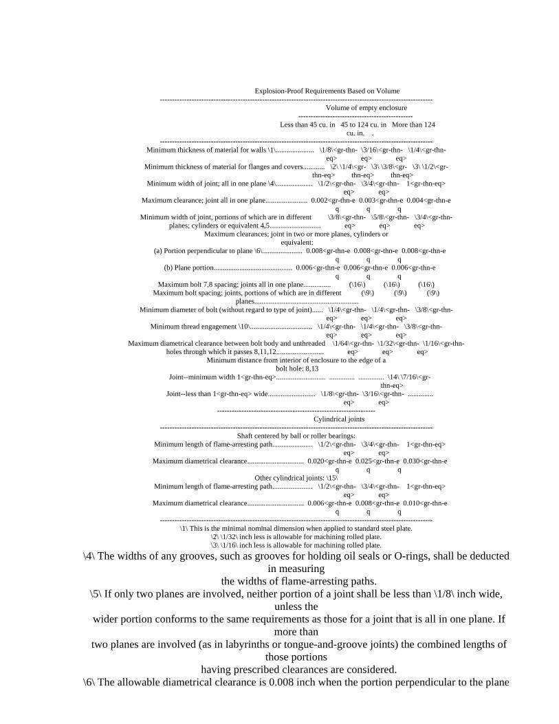
Explosion-Proof Requirements Based on Volume ----------------------------------------------------------------------------------------------------------------
Volume of empty enclosure -----------------------------------------------
Less than 45 cu. in 45 to 124 cu. in More than 124 cu. in. .
---------------------------------------------------------------------------------------------------------------- Minimum thickness of material for walls \1\..................... \1/8\<gr-thn- \3/16\<gr-thn- \1/4\<gr-thn-
eq> eq> eq> Minimum thickness of material for flanges and covers............ \2\ \1/4\<gr- \3\ \3/8\<gr- \3\ \1/2\<gr-
thn-eq> thn-eq> thn-eq> Minimum width of joint; all in one plane \4\.................... \1/2\<gr-thn- \3/4\<gr-thn- 1<gr-thn-eq>
eq> eq> Maximum clearance; joint all in one plane....................... 0.002<gr-thn-e 0.003<gr-thn-e 0.004<gr-thn-e
q q q Minimum width of joint, portions of which are in different \3/8\<gr-thn- \5/8\<gr-thn- \3/4\<gr-thn-
planes; cylinders or equivalent 4,5............................ eq> eq> eq> Maximum clearances; joint in two or more planes, cylinders or
equivalent: (a) Portion perpendicular to plane \6\...................... 0.008<gr-thn-e 0.008<gr-thn-e 0.008<gr-thn-e
q q q (b) Plane portion........................................... 0.006<gr-thn-e 0.006<gr-thn-e 0.006<gr-thn-e
q q q Maximum bolt 7,8 spacing; joints all in one plane............... (\16\) (\16\) (\16\)
Maximum bolt spacing; joints, portions of which are in different (\9\) (\9\) (\9\) planes.........................................................
Minimum diameter of bolt (without regard to type of joint)...... \1/4\<gr-thn- \1/4\<gr-thn- \3/8\<gr-thn- eq> eq> eq>
Minimum thread engagement \10\.................................. \1/4\<gr-thn- \1/4\<gr-thn- \3/8\<gr-thn- eq> eq> eq>
Maximum diametrical clearance between bolt body and unthreaded \1/64\<gr-thn- \1/32\<gr-thn- \1/16\<gr-thn- holes through which it passes 8,11,12.......................... eq> eq> eq>
Minimum distance from interior of enclosure to the edge of a bolt hole: 8,13
Joint--minimum width 1<gr-thn-eq>........................... .............. .............. \14\ \7/16\<gr- thn-eq>
Joint--less than 1<gr-thn-eq> wide.......................... \1/8\<gr-thn- \3/16\<gr-thn- .............. eq> eq>
----------------------------------------------------------------- Cylindrical joints
---------------------------------------------------------------------------------------------------------------- Shaft centered by ball or roller bearings:
Minimum length of flame-arresting path...................... \1/2\<gr-thn- \3/4\<gr-thn- 1<gr-thn-eq> eq> eq>
Maximum diametrical clearance............................... 0.020<gr-thn-e 0.025<gr-thn-e 0.030<gr-thn-e q q q
Other cylindrical joints: \15\ Minimum length of flame-arresting path...................... \1/2\<gr-thn- \3/4\<gr-thn- 1<gr-thn-eq>
eq> eq> Maximum diametrical clearance............................... 0.006<gr-thn-e 0.008<gr-thn-e 0.010<gr-thn-e
q q q ----------------------------------------------------------------------------------------------------------------
\1\ This is the minimal nominal dimension when applied to standard steel plate. \2\ \1/32\ inch less is allowable for machining rolled plate. \3\ \1/16\ inch less is allowable for machining rolled plate.
\4\ The widths of any grooves, such as grooves for holding oil seals or O-rings, shall be deducted in measuring
the widths of flame-arresting paths. \5\ If only two planes are involved, neither portion of a joint shall be less than \1/8\ inch wide,
unless the wider portion conforms to the same requirements as those for a joint that is all in one plane. If
more than two planes are involved (as in labyrinths or tongue-and-groove joints) the combined lengths of
those portions having prescribed clearances are considered.
\6\ The allowable diametrical clearance is 0.008 inch when the portion perpendicular to the plane

portion is \1/ 4\ inch or greater in length. If the perpendicular portion is more than \1/8\ inch but less than
\1/4\ inch wide, the diametrical clearance shall not exceed 0.006 inch.
\7\ Where the term ``bolt'' is used, it refers to a machine bolt or a cap screw, and for either of these studs
may be substituted provided the studs, bottom in blind holes, are completely welded in place, or the bottom of
the hole is closed with a plug secured by weld or braze. Bolts shall be provided at all corners. \8\ The requirements as to diametrical clearance around the bolt and minimum distance from the
bolt hole to the inside of the explosion-proof enclosure apply to steel dowel pins. In addition, when such pins
are used, the spacing between centers of the bolts on either side of the pin shall not exceed 5 inches. \9\ Adequacy of bolt spacing will be judged on the basis of size and configuration of the
enclosure, strength of materials, and explosion test results.
\10\ In general, minimum thread engagement shall be equal to or greater than the diameter of the bolt specified.
\11\ Threaded holes for fastening bolts shall be machined to remove burrs or projections that affect planarity
of a surface forming a flame-arresting path. \12\ This maximum clearance applies only when the bolt is located within the flamepath.
\13\ The edge of the bolt hole shall include the edge of any machining done to the bolt hole, such as
chamfering. \14\ Less than \7/16\<gr-thn-eq> (\1/4\<gr-thn-eq> minimum) will be acceptable provided the
diametrical clearance for fastening bolts does not exceed \1/32\<gr-thn-eq>.
\15\ Shafts or operating rods through journal bearings shall be at least \1/4\<gr-thn-eq> in diameter. The
length of fit shall not be reduced when a push button is depressed. Operating rods shall have a shoulder or
head on the portion inside the enclosure. Essential parts riveted or bolted to the inside portion are
acceptable in lieu of a head or shoulder, but cotter pins and similar devices shall not be used. \16\ 6<gr-thn-eq> with a minimum of 4 bolts.
(7) O-rings, if used in a flame-arresting path, shall meet the
following: (i) When the flame-arresting path is in one plane, the o-ring shall
be located at least one-half the acceptable flame-arresting path length specified in paragraph (a)(6) of this section within the outside edge of
the path (see figure J-2 in the appendix to subpart J of part 7 of this chapter).
(ii) When the flame-arresting path is one of the plane-cylindrical type (step joint), the o-ring shall be located at least \1/2\ inch
within the outer edge of the plane portion (see figure J-3 in the appendix to subpart J of part 7 of this chapter), or at the junction of

the
[[Page 100]]
plane and cylindrical portion of the joint (see figure J-4 in the appendix to subpart J of part 7 of this chapter); or in the cylindrical portion (see figure J-5 in the appendix to subpart J of part 7 of this
chapter). (8) Mating parts comprising a pressed fit shall result in a minimum
interference of 0.001 inch between the parts. The minimum length of the pressed fit shall be equal to the minimum thickness requirement of paragraph (a)(6) of this section for the material in which the fit is
made. (b) Enclosures for potted components: Enclosures shall be rugged and
constructed with materials having 75 percent, or greater, of the thickness and flange width specified in paragraph (a) of this section.
These enclosures shall be provided with means for attaching hose conduit, unless energy carried by the cable is intrinsically safe.
(c) No assembly will be approved that requires the opening of an explosion-proof enclosure to operate a switch, rheostat, or other device
during normal operation of a machine.
[33 FR 4660, Mar. 19, 1968, as amended at 57 FR 61209, Dec. 23, 1992]
Sec. 18.32 Fastenings--additional requirements.
(a) Bolts, screws, or studs shall be used for fastening adjoining parts to prevent the escape of flame from an enclosure. Hinge pins or
clamps will be acceptable for this purpose provided MSHA determines them to be equally effective.
(b) Lockwashers shall be provided for all bolts, screws, and studs that secure parts of explosion-proof enclosures. Special fastenings
designed to prevent loosening will be acceptable in lieu of lockwashers, provided MSHA determines them to be equally effective.
(c) Fastenings shall be as uniform in size as practicable to preclude improper assembly.
(d) Holes for fastenings shall not penetrate to the interior of an explosion-proof enclosure, except as provided in paragraph (a)(9) of
Sec. 18.34, and shall be threaded to insure that a specified bolt or screw will not bottom even if its lockwasher is omitted.
(e) A minimum of \1/8\-inch of stock shall be left at the center of the bottom of each hole drilled for fastenings.
(f) Fastenings used for joints on explosion-proof enclosures shall not be used for attaching nonessential parts or for making electrical
connections. (g) The acceptable sizes for and spacings of fastenings shall be determined by the size of the enclosure, as indicated in Sec. 18.31.
(h) MSHA reserves the right to conduct explosion tests with standard bolts, nuts, cap screws, or studs substituted for any special high-

tensile strength fastening(s) specified by the applicant. (i) Coil-thread inserts, if used in holes for fastenings, shall meet
the following: (1) The inserts shall have internal screw threads.
(2) The holes for the inserts shall be drilled and tapped consistent with the insert manufacturer's specifications.
(3) The inserts shall be installed consistent with the insert manufacturer's specifications.
(4) The insert shall be of sufficient length to ensure the minimum thread engagement of fastening specified in Sec. 18.31(a)(6) of this
part.
[33 FR 4660, Mar. 19, 1968, as amended at 57 FR 61210, Dec. 23, 1992]
Sec. 18.33 Finish of surface joints.
Flat surfaces between bolt holes that form any part of a flame- arresting path shall be plane to within a maximum deviation of one-half the maximum clearance specified in Sec. 18.31(a)(6). All metal surfaces
forming a flame-arresting path shall be finished during the manufacturing process to not more than 250 microinches. A thin film of
nonhardening preparation to inhibit rusting may be applied to these finished metal surfaces as long as the final surface can be readily
wiped free of any foreign materials.
[57 FR 61210, Dec. 23, 1992]
Sec. 18.34 Motors.
Explosion-proof electric motor assemblies intended for use in approved equipment in underground mines that are specifically addressed
in part 7 of this chapter shall be approved under
[[Page 101]]
part 7 of this chapter after February 22, 1996. Those motor assemblies not specifically addressed under part 7 of this chapter shall be
accepted or certified under this part. (a) General. (1) Motors shall have explosion-proof enclosures. (2) Motors submitted to MSHA for test shall be equipped with unshielded bearings regardless of whether that type of bearing is
specified. (3) MSHA reserves the right to test motors with the maximum
clearance specified between the shaft and the mating part which forms the required flame-arresting path. Also reserved is the right to remachine these parts, at the applicant's expense, to specified
dimensions to provide the maximum clearance. Note: For example, a shaft with a diameter greater than 2 inches at
the flame-arresting portion might require such machining.

(4) Ball and roller bearings and oil seals will not be acceptable as flame-arresting paths; therefore, a separate path shall be provided
between the shaft and another part, preferably inby the bearing. The length and clearances of such flame-arresting path shall conform to the
requirements of Sec. 18.31. (5) Labyrinths or other arrangements that provide change(s) in direction of escaping gases will be acceptable but the use of small
detachable pieces shall not be permitted unless structurally unavoidable. The lengths of flame-arresting path(s) and clearance(s)
shall conform to the requirements of Sec. 18.31. (6) Oil seals shall be removed from motors prior to submission for
explosion tests. Note: Oil seals will be removed from motors prior to explosion tests and therefore may be omitted from motors submitted for investigation. (7) Openings for filling and draining bearing lubricants shall be so
located as to prevent escape of flame through them. (8) An outer bearing cap will not be considered as forming any part of a flame-arresting path unless the cap is used as a bearing cartridge. Note: The outer bearing cap will be omitted during explosion tests
unless it houses the bearing. (9) If unavoidable, holes may be made through motor casings for
bolts, studs, or screws to hold essential parts such as pole pieces, brush rigging, and bearing cartridges. Such parts shall be attached to
the casing by at least two fastenings. The threaded holes in these parts shall be blind, unless the fastenings are inserted from the inside, in
which case the fastenings shall not be accessible with the armature of the motor in place.
(b) Direct-current motors. For direct-current motors with narrow interpoles, the distance from the edge of the pole piece to any bolt hole in the frame shall be not less than \1/8\ inch. If the distance is \1/8\ to \1/4\ inch, the diametrical clearance for the pole bolt shall
not exceed \1/64\ inch for not less than \1/2\ inch through the frame. Furthermore, the pole piece shall have the same radius as the inner
surface of the frame. Pole pieces may be shimmed as necessary. (c) Alternating-current motors. Stator laminations that form a part of an explosion-proof enclosure will be acceptable provided: (1) The laminations and their end rings are fastened together under pressure;
(2) the joint between the end rings and the laminations is not less than \1/4\ inch, but preferably as close to 1 inch as possible; and (3) it
shall be impossible to insert a 0.0015-inch thickness gage to a depth exceeding \1/8\ inch between adjacent laminations or between end rings
and laminations. (d) Small motors (alternating- and direct-current). Motors having internal free volume not exceeding 350 cubic inches and joints not exceeding 32 inches in outer circumference will be acceptable for
investigation if provided with rabbet joints between the stator frame and the end bracket having the following dimensions:
Dimensions of Rabbet Joints--Inches

------------------------------------------------------------------------ Max Min. width Max. diametrical
Minimum total width of clamped clearance clearance radial of radial at axial portion portion portion
------------------------------------------------------------------------ \3/8\............................... \3/64\ 0.0015 0.003 \1/2\............................... \3/64\ .002 .003 \1/2\............................... \3/32\ .002 .004
------------------------------------------------------------------------
[33 FR 4660, Mar. 19, 1968, as amended at 57 FR 61210, Dec. 23, 1992]
[[Page 102]]
Sec. 18.35 Portable (trailing) cables and cords.
(a) Portable cables and cords used to conduct electrical energy to face equipment shall conform to the following:
(1) Have each conductor of a current-carrying capacity consistent with the Insulated Power Cable Engineers Association (IPCEA) standards.
(See Tables 1 and 2 in Appendix I.) (2) Have current-carrying conductors not smaller than No. 14 (AWG). Cords with sizes 14 to 10 (AWG) conductors shall be constructed with heavy jackets, the diameters of which are given in Table 6 in Appendix
I. (3) Be accepted as flame resistant under this part or approved under
subpart K of part 7 of this chapter. (4) Have short-circuit protection at the outby (circuit-connecting)
end of ungrounded conductors. (See Table 8 in Appendix I.) The fuse rating or trip setting shall be included in the assembler's
specifications. (5) Ordinarily the length of a portable (trailing) cable shall not
exceed 500 feet. Where the method of mining requires the length of a portable (trailing) cable to be more than 500 feet, such length of cable
shall be permitted only under the following prescribed conditions: (i) The lengths of portable (trailing) cables shall not exceed those specified in Table 9, Appendix I, titled ``Specifications for Portable
Cables Longer Than 500 Feet.'' (ii) Short-circuit protection shall be provided by a protective
device with an instantaneous trip setting as near as practicable to the maximum starting-current-inrush value, but the setting shall not exceed the trip value specified in MSHA approval for the equipment for which
the portable (trailing) cable furnishes electric power. (6) Have nominal outside dimensions consistent with IPCEA standards.
(See Tables 4, 5, 6, and 7 in Appendix I.) (7) Have conductors of No. 4 (AWG) minimum for direct-current mobile
haulage units or No. 6 (AWG) minimum for alternating-current mobile
haulage units. (8) Have not more than five well-made temporary splices in a single
length of portable cable. (b) Sectionalized portable cables will be acceptable provided the
connectors used inby the last open crosscut in a gassy mine meet the requirements of Sec. 18.41.
(c) A portable cable having conductors smaller than No. 6 (AWG), when used with a trolley tap and a rail clamp, shall have well insulated
single conductors not smaller than No. 6 (AWG) spliced to the outby end of each conductor. All splices shall be made in a workmanlike manner to
insure good electrical conductivity, insulation, and mechanical strength.
(d) Suitable provisions shall be made to facilitate disconnection of portable cable quickly and conveniently for replacement.
[33 FR 4660, Mar. 19, 1968; 33 FR 6343, Apr. 26, 1968, as amended at 57
FR 61223, Dec. 23, 1992]
Sec. 18.36 Cables between machine components.
(a) Cables between machine components shall have: (1) Adequate current-carrying capacity for the loads involved, (2) short-circuit
protection, (3) insulation compatible with the impressed voltage, and (4) flame-resistant properties unless totally enclosed within a flame-
resistant hose conduit or other flame-resistant material. (b) Cables between machine components shall be: (1) Clamped in place
to prevent undue movement, (2) protected from mechanical damage by position, flame-resistant hose conduit, metal tubing, or troughs
(flexible or threaded rigid metal conduit will not be acceptable), (3) isolated from hydraulic lines, and (4) protected from abrasion by
removing all sharp edges which they might contact. (c) Cables (cords) for remote-control circuits extending from
permissible equipment will be exempted from the requirements of conduit enclosure provided the total electrical energy carried is intrinsically
safe or that the cables are constructed with heavy jackets, the sizes of which are stated in Table 6 of Appendix I. Cables (cords) provided with
hose-conduit protection shall have a tensile strength not less than No. 16 (AWG) three-conductor, type SO cord. (Reference: 7.7.7 IPCEA Pub. No.
S-19-81, Fourth Edition.) Cables (cords) constructed with heavy
[[Page 103]]
jackets shall consist of conductors not smaller than No. 14 (AWG) regardless of the number of conductors.
Sec. 18.37 Lead entrances.
(a) Insulated cable(s), which must extend through an outside wall of
an explosion-proof enclosure, shall pass through a stuffing-box lead
entrance. All sharp edges that might damage insulation shall be removed from stuffing boxes and packing nuts.
(b) Stuffing boxes shall be so designed, and the amount of packing used shall be such, that with the packing properly compressed, the gland
nut still has a clearance distance of \1/8\ inch or more to travel without meeting interference by parts other than packing. In addition,
the gland nut shall have a minimum of three effective threads engaged. (See figures 8, 9 and 10 in appendix II.)
(c) Packing nuts and stuffing boxes shall be secured against loosening.
(d) Compressed packing material shall be in contact with the cable jacket for a length of not less than \1/2\ inch.
(e) Special requirements for glands in which asbestos-packing material is specified are:
(1) Asbestos-packing material shall be untreated, not less than \3/ 16\-inch diameter if round, or not less than \3/16\ by \3/16\ inch if
square. The width of the space for packing material shall not exceed by more than 50 percent the diameter or width of the uncompressed packing
material. (2) The allowable diametrical clearance between the cable and the
holes in the stuffing box and packing nut shall not exceed 75 percent of the nominal diameter or width of the packing material.
(f) Special requirements for glands in which a compressible material (example--synthetic elastomers) other than asbestos is specified, are:
(1) The packing material shall be flame resistant. (2) The radial clearance between the cable jacket and the nominal inside diameter of the packing material shall not exceed \1/32\-inch,
based on the nominal specified diameter of the cable. (3) The radial clearance between the nominal outside diameter of the
packing material and the inside wall of the stuffing box (that portion into which the packing material fits) shall not exceed \1/32\-inch.
[33 FR 4660, Mar. 19, 1968, as amended at 57 FR 61210, Dec. 23, 1992]
Sec. 18.38 Leads through common walls.
(a) Insulated studs will be acceptable for use in a common wall
between two explosion-proof enclosures. (b) When insulated wires or cables are extended through a common
wall between two explosion-proof enclosures in insulating bushings, such bushings shall be not less than 1-inch long and the diametrical
clearance between the wire or cable insulation and the holes in the bushings shall not exceed \1/16\-inch (based on the nominal specified diameter of the cable). The insulating bushings shall be secured in the
metal wall. (c) Insulated wires or cables conducted from one explosion-proof enclosure to another through conduit, tubing, piping, or other solid-
wall passageways will be acceptable provided one end of the passageway is plugged, thus isolating one enclosure from the other. Glands of
secured bushings with close-fitting holes through which the wires or cables are conducted will be acceptable for plugging. The tubing or duct specified for the passageway shall be brazed or welded into the walls of
both explosion-proof enclosures with continuous gas-tight welds. (d) If wires and cables are taken through openings closed with
sealing compounds, the design of the opening and characteristics of the compounds shall be such as to hold the sealing material in place without tendency of the material to crack or flow out of its place. The material
also must withstand explosion tests without cracking or loosening. (e) Openings through common walls between explosion-proof enclosures not provided with bushings or sealing compound, shall be large enough to
prevent pressure piling.
Sec. 18.39 Hose conduit.
Hose conduit shall be provided for mechanical protection of all machine cables that are exposed to damage. Hose conduit shall be flame
resistant and have a minimum wall thickness of
[[Page 104]]
\3/16\ inch. The flame resistance of hose conduit will be determined in accordance with the requirements of Sec. 18.65.
Sec. 18.40 Cable clamps and grips.
Insulated clamps shall be provided for all portable (trailing)
cables to prevent strain on the cable terminals of a machine. Also insulated clamps shall be provided to prevent strain on both ends of
each cable or cord leading from a machine to a detached or separately mounted component. Cable grips anchored to the cable may be used in lieu
of insulated strain clamps. Supporting clamps for cables used for wiring around machines shall be provided in a manner acceptable to MSHA.
Sec. 18.41 Plug and receptacle-type connectors.
(a) Plug and receptacle-type connectors for use inby the last open
crosscut in a gassy mine shall be so designed that insertion or withdrawal of a plug cannot cause incendive arcing or sparking. Also,
connectors shall be so designed that no live terminals, except as hereinafter provided, are exposed upon withdrawal of a plug. The
following types will be acceptable: (1) Connectors in which the mating or separation of the male and
female electrodes is accomplished within an explosion-proof enclosure. (2) Connectors that are mechanically or electrically interlocked
with an automatic circuit-interrupting device. (i) Mechanically interlocked connectors. If a mechanical interlock
is provided the design shall be such that the plug cannot be withdrawn before the circuit has been interrupted and the circuit cannot be
established with the plug partially withdrawn. (ii) Electrically interlocked connectors. If an electrical interlock is provided, the total load shall be removed before the plug can be withdrawn and the electrical energy in the interlocking pilot circuit shall be intrinsically safe, unless the pilot circuit is opened within
an explosion-proof enclosure. (3) Single-pole connectors for individual conductors of a circuit used at terminal points shall be so designed that all plugs must be
completely inserted before the control circuit of the machine can be energized.
(b) Plug and receptacle-type connectors used for sectionalizing the cables outby the last open crosscut in a gassy mine need not be
explosion-proof or electrically interlocked provided such connectors are designed and constructed to prevent accidental separation.
(c) Conductors shall be securely attached to the electrodes in a plug or receptacle and the connections shall be totally enclosed. (d) Molded-elastomer connectors will be acceptable provided:
(1) Any free space within the plug or receptacle is isolated from the exterior of the plug.
(2) Joints between the elastomer and metal parts are not less than 1 inch wide and the elastomer is either bonded to or fits tightly with
metal parts. (e) The contacts of all line-side connectors shall be shielded or
recessed adequately. (f) For a mobile battery-powered machine, a plug and receptacle-type
connector will be acceptable in lieu of an interlock provided: (1) The plug is padlocked to the receptacle and is held in place by a threaded ring or equivalent mechanical fastening in addition to a
padlock. A connector within a padlocked enclosure will be acceptable; or,
(2) The plug is held in place by a threaded ring or equivalent mechanical fastening, in addition to the use of a device that is captive and requires a special tool to disengage and allow for the separation of
the connector. All connectors using this means of compliance shall have a clearly visible warning tag that states: ``DO NOT DISENGAGE UNDER
LOAD,'' or an equivalent statement; or, (3) The plug is held in place by a spring-loaded or other locking device, that maintains constant pressure against a threaded ring or
equivalent mechanical fastening, to secure the plug from accidental separation. All connectors using this means of compliance shall have a
clearly visible warning tag that states: ``DO NOT DISENGAGE UNDER LOAD,'' or an equivalent statement.
[33 FR 4660, Mar. 19, 1968, as amended at 68 FR 37082, June 23, 2003]
[[Page 105]]
Sec. 18.42 Explosion-proof distribution boxes.
(a) A cable passing through an outside wall(s) of a distribution box shall be conducted either through a packing gland or an interlocked plug
and receptacle. (b) Short-circuit protection shall be provided for each branch
circuit connected to a distribution box. The current-carrying capacity of the specified connector shall be compatible with the automatic
circuit-interrupting device. (c) Each branch receptacle shall be plainly and permanently marked
to indicate its current-carrying capacity and each receptacle shall be such that it will accommodate only an appropriate plug.
(d) Provision shall be made to relieve mechanical strain on all connectors to distribution boxes.
Sec. 18.43 Explosion-proof splice boxes.
Internal connections shall be rigidly held and adequately insulated. Strain clamps shall be provided for all cables entering a splice box.
Sec. 18.44 Non-intrinsically safe battery-powered equipment.
(a) Battery-powered equipment shall use battery assemblies approved
under Part 7 of this chapter, or battery assemblies accepted or certified under this part prior to August 22, 1989.
(b) Battery box covers shall be secured in a closed position. (c) Each wire or cable leaving a battery box on storage battery-
operated equipment shall have short-circuit protection in an explosion- proof enclosure located as close as practicable to the battery
terminals. A short-circuit protection device installed within a nearby explosion-proof enclosure will be acceptable. In no case shall the exposed portion of the cable from the battery box to the enclosure
exceed 36 inches in length. Each wire or cable shall be protected from damage.
[53 FR 23500, June 22, 1988]
Sec. 18.45 Cable reels.
(a) A self-propelled machine, that receives electrical energy
through a portable cable and is designed to travel at speeds exceeding 2.5 miles per hour, shall have a mechanically, hydraulically, or electrically driven reel upon which to wind the portable cable.
(b) The enclosure for moving contacts or slip rings of a cable reel shall be explosion-proof.
(c) Cable-reel bearings shall not constitute an integral part of a circuit for transmitting electrical energy.
(d) Cable reels for shuttle cars and locomotives shall maintain positive tension on the portable cable during reeling and unreeling.
Such tension shall only be high enough to prevent a machine from running over its own cable(s).

(e) Cable reels and spooling devices shall be insulated with flame- resistant material.
(f) The maximum speed of travel of a machine when receiving power through a portable (trailing) cable shall not exceed 6 miles per hour.
(g) Diameters of cable reel drums and sheaves should be large enough to prevent undue bending strain on cables.
Sec. 18.46 Headlights.
(a) Headlights shall be constructed as explosion-proof enclosures. (b) Headlights shall be mounted to provide illumination where it
will be most effective. They shall be protected from damage by guarding or location.
(c) Lenses for headlights shall be glass or other suitable material with physical characteristics equivalent to \1/2\-inch thick tempered
glass, such as ``Pyrex.'' Lenses shall meet the requirements of the tests prescribed in Sec. 18.66.
(d) Lenses permanently fixed in a ring with lead, epoxy, or equivalent will be acceptable provided only lens assemblies meeting the
original manufacturer's specifications are used as replacements. (e) If a single lead gasket is used, the contact surface of the
opposite side of the lens shall be plane within a maximum deviation of 0.002 inch.
Sec. 18.47 Voltage limitation.
(a) A tool or switch held in the operator's hand or supported
against his body will not be approved with a nameplate rating exceeding 300 volts direct current or alternating current.
[[Page 106]]
(b) A battery-powered machine shall not have a nameplate rating
exceeding 240 volts, nominal (120 lead-acid cells or equivalent). (c) Other direct-current machines shall not have a nameplate rating
exceeding 550 volts. (d) An alternating-current machine shall not have a nameplate rating
exceeding 660 volts, except that a machine may have a nameplate rating greater than 660 volts but not exceeding 4,160 volts when the following
conditions are complied with: (1) Adequate clearances and insulation for the particular voltage(s)
are provided in the design and construction of the equipment, its wiring, and accessories.
(2) A continuously monitored, failsafe grounding system is provided that will maintain the frame of the equipment and the frames of all
accessory equipment at ground potential. Also, the equipment, including its controls and portable (trailing) cable, will be deenergized
automatically upon the occurrence of an incipient ground fault. The ground-fault-tripping current shall be limited by grounding resistor(s)

to that necessary for dependable relaying. The maximum ground-fault- tripping current shall not exceed 25 amperes.
(3) All high voltage switch gear and control for equipment having a nameplate rating exceeding 1,000 volts are located remotely and operated
by remote control at the main equipment. Potential for remote control shall not exceed 120 volts.
(4) Portable (trailing) cable for equipment with nameplate ratings from 661 volts through 1,000 volts shall include grounding conductors, a
ground check conductor, and grounded metallic shields around each power conductor or a grounded metallic shield over the assembly; except that
on machines employing cable reels, cables without shields may be used if the insulation is rated 2,000 volts or more.
(5) Portable (trailing) cable for equipment with nameplate ratings from 1,001 volts through 4,160 volts shall include grounding conductors,
a ground check conductor, and grounded metallic shields around each power conductor.
(6) MSHA reserves the right to require additional safeguards for high-voltage equipment, or modify the requirements to recognize improved
technology.
Sec. 18.48 Circuit-interrupting devices.
(a) Each machine shall be equipped with a circuit-interrupting device by means of which all power conductors can be deenergized at the
machine. A manually operated controller will not be acceptable as a service switch.
(b) When impracticable to mount the main-circuit-interrupting device on a machine, a remote enclosure will be acceptable. When contacts are
used as a main-circuit-interrupting device, a means for opening the circuit shall be provided at the machine and at the remote contactors.
(c) Separate two-pole switches shall be provided to deenergize power conductors for headlights or floodlights.
(d) Each handheld tool shall be provided with a two-pole switch of the ``dead-man-control'' type that must be held closed by hand and will
open when hand pressure is released. (e) A machine designed to operate from both trolley wire and
portable cable shall be provided with a transfer switch, or equivalent, which prevents energizing one from the other. Such a switch shall be
designed to prevent electrical connection to the machine frame when the cable is energized.
(f) Belt conveyors shall be equipped with control switches to automatically stop the driving motor in the event the belt is stopped,
or abnormally slowed down. Note: Short transfer-type conveyors will be exempted from this
requirement when attended.
Sec. 18.49 Connection boxes on machines.
Connection boxes used to facilitate replacement of cables or machine

components shall be explosion-proof. Portable-cable terminals on cable reels need not be in explosion-proof enclosures provided that
connections are well made, adequately insulated, protected from damage by location, and securely clamped to prevent mechanical strain on the
connections.
[[Page 107]]
Sec. 18.50 Protection against external arcs and sparks.
Provision shall be made for maintaining the frames of all off-track machines and the enclosures of related detached components at safe
voltages by using one or a combination of the following: (a) A separate conductor(s) in the portable cable in addition to the
power conductors by which the machine frame can be connected to an acceptable grounding medium, and a separate conductor in all cables connecting related components not on a common chassis. The cross- sectional area of the additional conductor(s) shall not be less than 50 percent of that of one power conductor unless a ground-fault tripping
relay is used, in which case the minimum size may be No. 8 (AWG). Cables smaller than No. 6 (AWG) shall have an additional conductor(s) of the
same size as one power conductor. (b) A means of actuating a circuit-interrupting device, preferably
at the outby end of the portable cable. Note: The frame to ground potential shall not exceed 40 volts.
(c) A device(s) such as a diode(s) of adequate peak inverse voltage rating and current-carrying capacity to conduct possible fault current
through the grounded power conductor. Diode installations shall include: (1) An overcurrent device in series with the diode, the contacts of
which are in the machine's control circuit; and (2) a blocking diode in the control circuit to prevent operation of the machine with the
polarity reversed.
Sec. 18.51 Electrical protection of circuits and equipment.
(a) An automatic circuit-interrupting device(s) shall be used to protect each ungrounded conductor of a branch circuit at the junction
with the main circuit when the branch-circuit conductor(s) has a current carrying capacity less than 50 percent of the main circuit conductor(s),
unless the protective device(s) in the main circuit will also provide adequate protection for the branch circuit. The setting of each device shall be specified. For headlight and control circuits, each conductor shall be protected by a fuse or equivalent. Any circuit that is entirely contained in an explosion-proof enclosure shall be exempt from these
requirements. (b) Each motor shall be protected by an automatic overcurrent
device. One protective device will be acceptable when two motors of the same rating operate simultaneously and perform virtually the same duty.
(1) If the overcurrent-protective device in a direct-current circuit

does not open both lines, particular attention shall be given to marking the polarity at the terminals or otherwise preventing the possibility of
reversing connections which would result in changing the circuit interrupter to the grounded line.
(2) Three-phase alternating-current motors shall have an overcurrent-protective device in at least two phases such that actuation
of a device in one phase will cause the opening of all three phases. (c) Circuit-interrupting devices shall be so designed that they can
be reset without opening the compartment in which they are enclosed. (d) All magnetic circuit-interrupting devices shall be mounted in a
manner to preclude the possibility of their closing by gravity.
Sec. 18.52 Renewal of fuses.
Enclosure covers that provide access to fuses, other than headlight, control-circuit, and handheld-tool fuses, shall be interlocked with a
circuit-interrupting device. Fuses shall be inserted on the load side of the circuit interrupter.
Sec. 18.53 High-voltage longwall mining systems.
(a) In each high-voltage motor-starter enclosure, with the exception
of a controller on a high-voltage shearer, the disconnect device compartment, control/communications compartment, and motor contactor
compartment must be separated by barriers or partitions to prevent exposure of personnel to energized high-voltage conductors or parts. In each motor-starter enclosure on a high-voltage shearer, the high-voltage
components must be separated from lower voltage components by barriers or partitions to prevent exposure of personnel to energized high-voltage
[[Page 108]]
conductors or parts. Barriers or partitions must be constructed of
grounded metal or nonconductive insulating board. (b) Each cover of a compartment in the high-voltage motor-starter
enclosure containing high-voltage components must be equipped with at least two interlock switches arranged to automatically deenergize the high-voltage components within that compartment when the cover is
removed. (c) Circuit-interrupting devices must be designed and installed to
prevent automatic reclosure. (d) Transformers with high-voltage primary windings that supply control voltages must incorporate grounded electrostatic (Faraday)
shielding between the primary and secondary windings. The shielding must be connected to equipment ground by a minimum No. 12 AWG grounding conductor. The secondary nominal voltage must not exceed 120 volts, line
to line. (e) Test circuits must be provided for checking the condition of
ground-wire monitors and ground-fault protection without exposing

personnel to energized circuits. Each ground-test circuit must inject a primary current of 50 percent or less of the current rating of the
grounding resistor through the current transformer and cause each corresponding circuit-interrupting device to open.
(f) Each motor-starter enclosure, with the exception of a controller on a high-voltage shearer, must be equipped with a disconnect device
installed to deenergize all high-voltage power conductors extending from the enclosure when the device is in the ``open'' position.
(1) When multiple disconnect devices located in the same enclosure are used to satisfy the above requirement they must be mechanically
connected to provide simultaneous operation by one handle. (2) The disconnect device must be rated for the maximum phase-to-
phase voltage and the full-load current of the circuit in which it is located, and installed so that--
(i) Visual observation determines that the contacts are open without removing any cover;
(ii) The load-side power conductors are grounded when the device is in the ``open'' position;
(iii) The device can be locked in the ``open'' position; (iv) When located in an explosion-proof enclosure, the device must
be designed and installed to cause the current to be interrupted automatically prior to the opening of the contacts; and
(v) When located in a non-explosion-proof enclosure, the device must be designed and installed to cause the current to be interrupted
automatically prior to the opening of the contacts, or the device must be capable of interrupting the full-load current of the circuit.
(g) Control circuits for the high-voltage motor starters must be interlocked with the disconnect device so that--
(1) The control circuit can be operated with an auxiliary switch in the ``test'' position only when the disconnect device is in the open and
grounded position; and (2) The control circuit can be operated with the auxiliary switch in
the ``normal'' position only when the disconnect switch is in the closed position.
(h) A study to determine the minimum available fault current must be submitted to MSHA to ensure adequate protection for the length and
conductor size of the longwall motor, shearer and trailing cables. (i) Longwall motor and shearer cables with nominal voltages greater than 660 volts must be made of a shielded construction with a grounded
metallic shield around each power conductor. (j) High-voltage motor and shearer circuits must be provided with
instantaneous ground-fault protection of not more than 0.125-amperes. Current transformers used for this protection must be of the single-
window type and must be installed to encircle all three phase conductors.
(k) Safeguards against corona must be provided on all 4,160 voltage circuits in explosion-proof enclosures.
(l) The maximum pressure rise within an explosion-proof enclosure containing high-voltage switchgear must
[[Page 109]]
be limited to 0.83 times the design pressure.
(m) High-voltage electrical components located in high-voltage explosion-proof enclosures must not be coplanar with a single plane
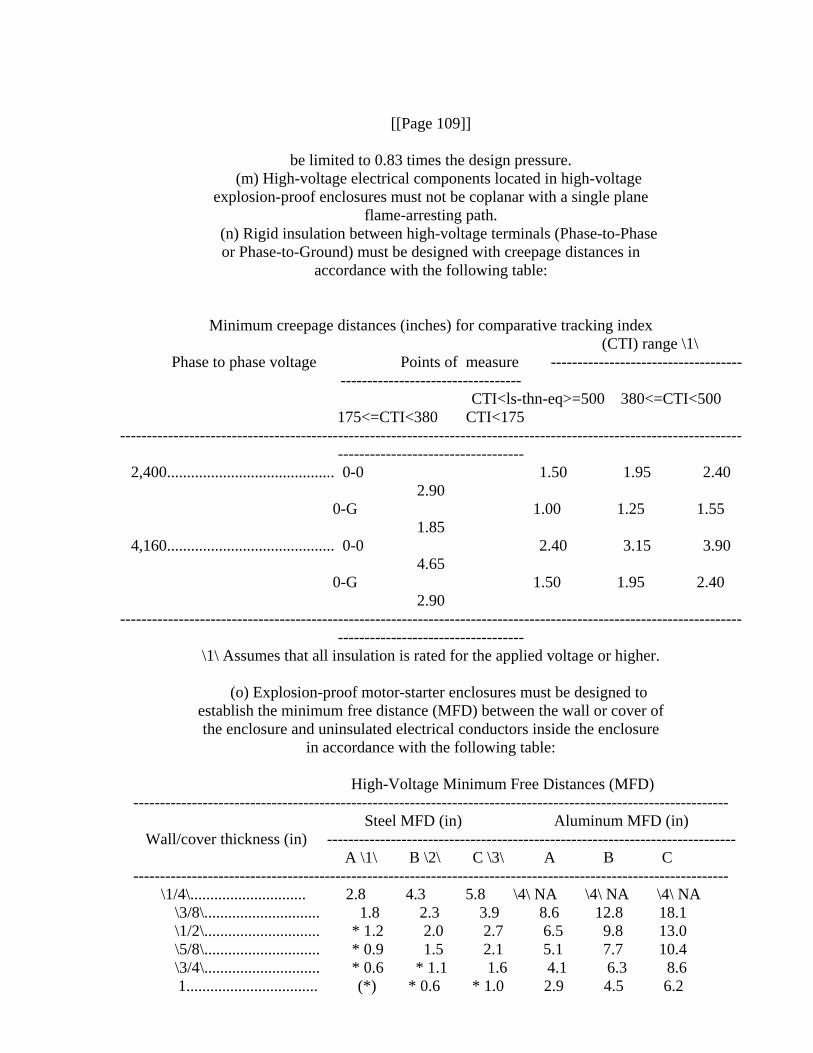
flame-arresting path. (n) Rigid insulation between high-voltage terminals (Phase-to-Phase
or Phase-to-Ground) must be designed with creepage distances in accordance with the following table:
Minimum creepage distances (inches) for comparative tracking index (CTI) range \1\
Phase to phase voltage Points of measure ----------------------------------------------------------------------
CTI<ls-thn-eq>=500 380<=CTI<500 175<=CTI<380 CTI<175
--------------------------------------------------------------------------------------------------------------------------------------------------------
2,400.......................................... 0-0 1.50 1.95 2.40 2.90
0-G 1.00 1.25 1.55 1.85
4,160.......................................... 0-0 2.40 3.15 3.90 4.65
0-G 1.50 1.95 2.40 2.90
--------------------------------------------------------------------------------------------------------------------------------------------------------
\1\ Assumes that all insulation is rated for the applied voltage or higher.
(o) Explosion-proof motor-starter enclosures must be designed to establish the minimum free distance (MFD) between the wall or cover of the enclosure and uninsulated electrical conductors inside the enclosure
in accordance with the following table:
High-Voltage Minimum Free Distances (MFD) ----------------------------------------------------------------------------------------------------------------
Steel MFD (in) Aluminum MFD (in) Wall/cover thickness (in) -----------------------------------------------------------------------------
A \1\ B \2\ C \3\ A B C ----------------------------------------------------------------------------------------------------------------
\1/4\............................. 2.8 4.3 5.8 \4\ NA \4\ NA \4\ NA \3/8\............................. 1.8 2.3 3.9 8.6 12.8 18.1 \1/2\............................. * 1.2 2.0 2.7 6.5 9.8 13.0 \5/8\............................. * 0.9 1.5 2.1 5.1 7.7 10.4 \3/4\............................. * 0.6 * 1.1 1.6 4.1 6.3 8.6 1................................. (*) * 0.6 * 1.0 2.9 4.5 6.2

---------------------------------------------------------------------------------------------------------------- Note: * The minimum electrical clearances must still be maintained.
\1\ Column A specifies the MFD for enclosures that have available 3-phase bolted short-circuit currents of
10,000 amperes rms or less. \2\ Column B specifies the MFD for enclosures that have a maximum available 3-phase bolted
short-circuit currents greater than 10,000 and less than or equal to 15,000 amperes rms.
\3\ Column C specifies the MFD for enclosures that have a maximum available 3-phase bolted short-circuit
currents greater than 15,000 and less than or equal to 20,000 amperes rms. \4\ Not Applicable--MSHA doesn't allow aluminum wall or covers to be \1/4\ inch or less in
thickness (Section 18.31).
(1) For values not included in the table, the following formulas on which the table is based may be used to determine the minimum free
distance. (i) Steel Wall/Cover:
[GRAPHIC] [TIFF OMITTED] TR23NO04.000
(ii) Aluminum Wall/Cover: [GRAPHIC] [TIFF OMITTED] TR23NO04.001
[[Page 110]]
Where C is 1.4 for 2,400 volt systems or 3.0 for 4,160 volt systems, I<INF>sc</INF> is the 3-phase short circuit current in amperes of the
system, t is the clearing time in seconds of the outby circuit- interrupting device and d is the thickness in inches of the metal wall/
cover adjacent to an area of potential arcing. (2) The minimum free distance must be increased by 1.5 inches for
4,160 volt systems and 0.7 inches for 2,400 volt systems when the adjacent wall area is the top of the enclosure. If a steel shield is
mounted in conjunction with an aluminum wall or cover, the thickness of the steel shield is used to determine the minimum free distances.
(p) The following static pressure test must be performed on each prototype design of explosion-proof enclosures containing high-voltage
switchgear prior to the explosion tests. The static pressure test must also be performed on every explosion-proof enclosure containing high- voltage switchgear, at the time of manufacture, unless the manufacturer
uses an MSHA accepted quality assurance procedure covering inspection of the enclosure. Procedures must include a detailed check of parts against the drawings to determine that the parts and the drawings coincide and
that the minimum requirements stated in part 18 have been followed with respect to materials, dimensions,configuration and workmanship.
(1) Test procedure. (i) The enclosure must be internally pressurized to at least the design pressure, maintaining the pressure for a minimum
of 10 seconds. (ii) Following the pressure hold, the pressure must be removed and
the pressurizing agent removed from the enclosure. (2) Acceptable performance. (i) The enclosure during pressurization
must not exhibit-- (A) Leakage through welds or casting; or
(B) Rupture of any part that affects the explosion-proof integrity of the enclosure.
(ii) The enclosure following removal of the pressurizing agents must not exhibit--
(A) Visible cracks in welds; (B) Permanent deformation exceeding 0.040 inches per linear foot; or
(C) Excessive clearances along flame-arresting paths following retightening of fastenings, as necessary.
[67 FR 10999, Mar. 11, 2002; 69 FR 68078, Nov. 23, 2004; 69 FR 70752,
Dec. 7, 2004]
Subpart C_Inspections and Tests
Sec. 18.60 Detailed inspection of components.
An inspection of each electrical component shall include the following:
(a) A detailed check of parts against the drawings submitted by the applicant to determine that: (1) The parts and drawings coincide; and (2) the minimum requirements stated in this part have been met with respect to materials, dimensions, configuration, workmanship, and
adequacy of drawings and specifications. (b) Exact measurement of joints, journal bearings, and other flame-
arresting paths. (c) Examination for unnecessary through holes.
(d) Examination for adequacy of lead-entrance design and construction.
(e) Examination for adequacy of electrical insulation and clearances between live parts and between live parts and the enclosure.
(f) Examination for weaknesses in welds and flaws in castings. (g) Examination for distortion of enclosures before tests.
(h) Examination for adequacy of fastenings, including size, spacing, security, and possibility of bottoming.
Sec. 18.61 Final inspection of complete machine.
(a) A completely assembled new machine or a substantially modified
design of a previously approved one shall be inspected by a qualified representative(s) of MSHA. When such inspection discloses any unsafe condition or any feature not in strict conformance with the requirements
of this part it shall be corrected before an approval of the machine will be issued. A final inspection will be conducted at the site of
manufacture, rebuilding, or other locations at the option of MSHA. (b) Complete machines shall be inspected for:
(1) Compliance with the requirements of this part with respect to joints, lead
[[Page 111]]
entrances, and other pertinent features.
(2) Wiring between components, adequacy of mechanical protection for cables, adequacy of clamping of cables, positioning of cables,
particularly with respect to proximity to hydraulic components. (3) Adequacy of protection against damage to headlights, push
buttons, and any other vulnerable component. (4) Settings of overload- and short-circuit protective devices.
(5) Adequacy of means for connecting and protecting portable cable.
Sec. 18.62 Tests to determine explosion-proof characteristics.
(a) In testing for explosion-proof characteristics of an enclosure, it shall be filled and surrounded with various explosive mixtures of
natural gas and air. The explosive mixture within the enclosure will be ignited electrically and the explosion pressure developed therefrom recorded. The point of ignition within the enclosure will be varied. Motor armatures and/or rotors will be stationary in some tests and revolving in others. Coal dust having a minimum of 22 percent dry
volatile matter and a minimum heat constant of 11,000 moist BTU (coal containing natural bed moisture but not visible surface water) ground to a fineness of minus 200 mesh U.S. Standard sieve series. At MSHA's
discretion dummies may be substituted for internal electrical components during some of the tests. Not less than 16 explosion tests shall be
conducted; however, the nature of the enclosure and the results obtained during the tests will determine whether additional tests shall be made.
(b) Explosion tests of an enclosure shall not result in: (1) Discharge of flame.
(2) Ignition of an explosive mixture surrounding the enclosure. (3) Development of afterburning.
(4) Rupture of any part of the enclosure or any panel or divider within the enclosure.
(5) Permanent distortion of the enclosure exceeding 0.040 inch per linear foot.
(c) When a pressure exceeding 125 pounds per square inch (gage) is developed during explosion tests, MSHA reserves the right to reject an enclosure(s) unless (1) constructional changes are made that result in a reduction of pressure to 125 pounds per square inch (gage) or less, or (2) the enclosure withstands a dynamic pressure of twice the highest
value recorded in the initial test.

[33 FR 4660, Mar. 19, 1968, as amended at 57 FR 61210, Dec. 23, 1992]
Sec. 18.63 [Reserved]
Sec. 18.65 Flame test of conveyor belting and hose.
(a) Size of test specimen. (1) Conveyor belting--four specimens each 6 inches long by \1/2\-inch wide by belt thickness, two cut parallel to
the warp and two parallel to the weft. (2) Hose--four specimens each 6 inches long by \1/2\-inch wide by
thickness of the hose. (b) Flame-test apparatus. The principal parts of the apparatus
within and/or appended to a 21-inch cubical test gallery are: (1) A support stand with a ring clamp and wire gauze.
(2) A Pittsburgh-Universal Bunsen-type burner (inside diameter of burner tube 11 mm.), or equivalent, mounted in a burner placement guide
in such a manner that the burner may be placed beneath the test specimen, or pulled away from it by an external knob on the front panel
of the test gallery. (3) A variable-speed electric fan and an ASME flow nozzle (16-8\1/2\ inches reduction) to attain constant air velocities at any speed between
50-500 feet a minute. (4) An electric timer or stopwatch to measure the duration of the
tests. (5) A mirror mounted inside the test gallery to permit a rear view
of the test specimen through the viewing door. (c) Mounting of test specimen. The specimen shall be clamped in a
support with its free end centered 1 inch above the burner top. The longitudinal axis shall be horizontal and the transverse axis inclined
at 45[deg] to the horizontal. Under the test specimen shall be clamped a piece of 20-mesh iron-wire gauze, 5 inches square, in a horizontal
position \1/4\-inch below the pulley cover edge of the specimen and with about
[[Page 112]]
\1/2\-inch of the specimen extending beyond the edge of the gauze.
(d) Procedure for flame tests. (1) The Bunsen burner, retracted from the test position, shall be adjusted to give a blue flame 3 inches in
height with natural gas. (2) The observation door of the gallery shall be closed for the
entire test. (3) The burner flame shall be applied to the free end of the
specimen for 1 minute in still air. (4) At the end of 1 minute the burner flame shall be removed, the ventilating fan turned on to give an air current having a velocity of
300 feet per minute, and the duration of flame measured. (5) After the test specimen ceases to flame, it shall remain in the
air current for at least 3 minutes to determine the presence and
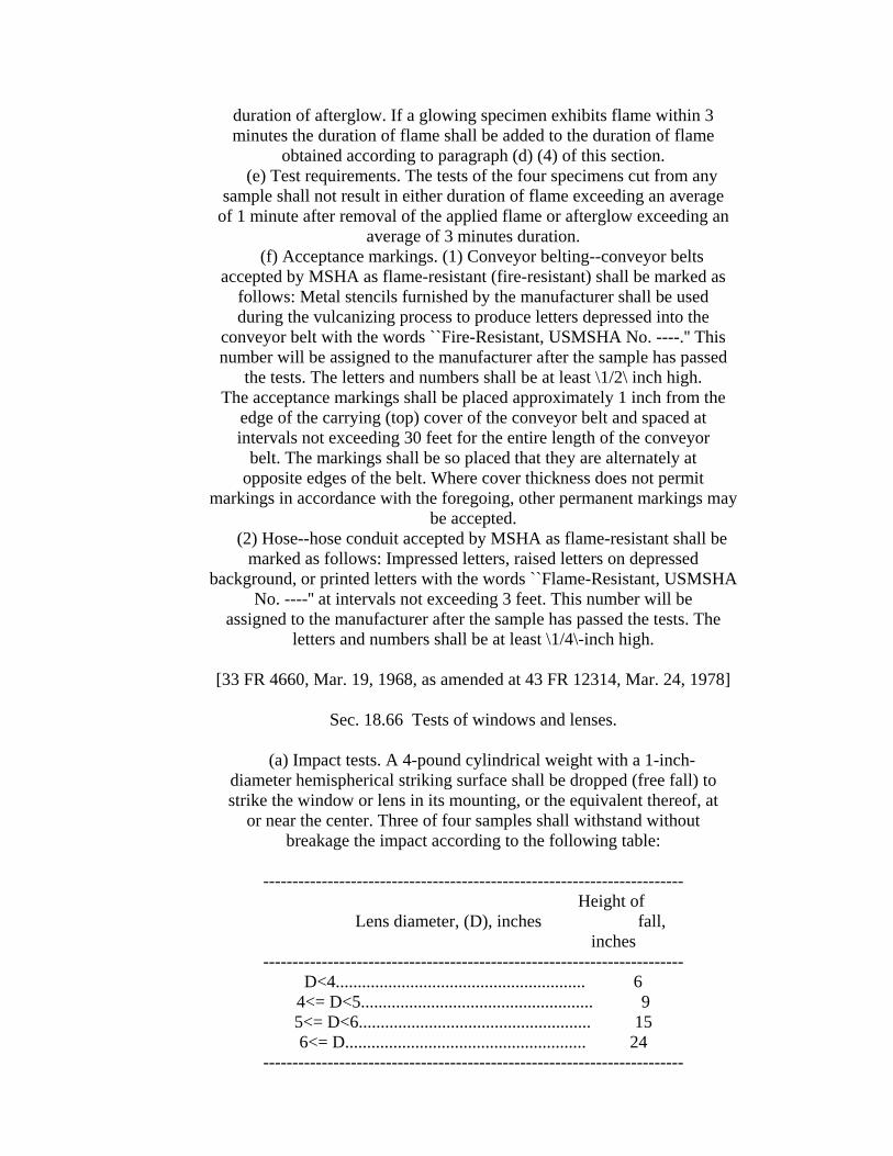
duration of afterglow. If a glowing specimen exhibits flame within 3 minutes the duration of flame shall be added to the duration of flame
obtained according to paragraph (d) (4) of this section. (e) Test requirements. The tests of the four specimens cut from any
sample shall not result in either duration of flame exceeding an average of 1 minute after removal of the applied flame or afterglow exceeding an
average of 3 minutes duration. (f) Acceptance markings. (1) Conveyor belting--conveyor belts
accepted by MSHA as flame-resistant (fire-resistant) shall be marked as follows: Metal stencils furnished by the manufacturer shall be used during the vulcanizing process to produce letters depressed into the
conveyor belt with the words ``Fire-Resistant, USMSHA No. ----.'' This number will be assigned to the manufacturer after the sample has passed
the tests. The letters and numbers shall be at least \1/2\ inch high. The acceptance markings shall be placed approximately 1 inch from the
edge of the carrying (top) cover of the conveyor belt and spaced at intervals not exceeding 30 feet for the entire length of the conveyor
belt. The markings shall be so placed that they are alternately at opposite edges of the belt. Where cover thickness does not permit
markings in accordance with the foregoing, other permanent markings may be accepted.
(2) Hose--hose conduit accepted by MSHA as flame-resistant shall be marked as follows: Impressed letters, raised letters on depressed
background, or printed letters with the words ``Flame-Resistant, USMSHA No. ----'' at intervals not exceeding 3 feet. This number will be
assigned to the manufacturer after the sample has passed the tests. The letters and numbers shall be at least \1/4\-inch high.
[33 FR 4660, Mar. 19, 1968, as amended at 43 FR 12314, Mar. 24, 1978]
Sec. 18.66 Tests of windows and lenses.
(a) Impact tests. A 4-pound cylindrical weight with a 1-inch-
diameter hemispherical striking surface shall be dropped (free fall) to strike the window or lens in its mounting, or the equivalent thereof, at
or near the center. Three of four samples shall withstand without breakage the impact according to the following table:
------------------------------------------------------------------------
Height of Lens diameter, (D), inches fall,
inches ------------------------------------------------------------------------
D<4......................................................... 6 4<= D<5..................................................... 9 5<= D<6..................................................... 15 6<= D....................................................... 24
------------------------------------------------------------------------

Windows or lenses of smaller diameter than 1 inch may be tested by
alternate methods at the discretion of MSHA. (b) Thermal-shock tests. Four samples of the window or lens will be heated in an oven for 15 minutes to a temperature of 150 [deg]C. (302
[deg]F.) and immediately upon withdrawal of the samples from the oven they will be immersed in water having a temperature between 15 [deg]C. (59 [deg]F) and 20 [deg]C. (68 [deg]F.). Three of the four samples shall
show no defect or breakage from this thermal-shock test.
Sec. 18.67 Static-pressure tests.
Static-pressure tests shall be conducted by the applicant on each enclosure of a specific design when MSHA determines that visual
inspection will not reveal defects in castings or in single-seam welds. Such test procedure shall be submitted to MSHA for approval and the
specifications on file with MSHA shall include a statement
[[Page 113]]
assuring that such tests will be conducted. The static pressure to be applied shall be 150 pounds per square inch (gage) or one and one-half
times the maximum pressure recorded in MSHA's explosion tests, whichever is greater.
Sec. 18.68 Tests for intrinsic safety.
(a) General:
(1) Tests for intrinsic safety will be conducted under the general concepts of ``intrinsically safe'' as defined in Subpart A of this part. Further tests or requirements may be added at any time if features of construction or use or both indicate them to be necessary. Some tests
included in these requirements may be omitted on the basis of previous experience.
(2) Intrinsically safe circuits and/or components will be subjected to tests consisting of making and breaking the intrinsically safe
circuit under conditions judged to simulate the most hazardous probable faults or malfunctions. Tests will be made in the most easily ignitable mixture of methane or natural gas and air. The method of making and
breaking the circuit may be varied to meet a particular condition. (3) Those components which affect intrinsic safety must meet the
following requirements: (i) Current limiting components shall consist of two equivalent
devices each of which singly will provide intrinsic safety. They shall not be operated at more than 50 percent of their ratings.
(ii) Components of reliable construction shall be used and they shall be so mounted as to provide protection against shock and vibration
in normal use. (iii) Semiconductors shall be amply sized. Rectifiers and

transistors shall be operated at not more than two-thirds of their rated current and permissible peak inverse voltage. Zener diodes shall be operated at not more than one-half of their rated current and shall
short under abnormal conditions. (iv) Electrolytic capacitors shall be operated at not more than two-
thirds of their rated voltage. They shall be designed to withstand a test voltage of 1,500 volts.
(4) Intrinsically safe circuits shall be so designed that after failure of a single component, and subsequent failures resulting from
this first failure, the circuit will remain intrinsically safe. (5) The circuit will be considered as intrinsically safe if in the
course of testing no ignitions occur. (b) Complete intrinsically safe equipment powered by low energy
batteries: (1) Short-circuit tests shall be conducted on batteries at normal operating temperature. Tests may be made on batteries at elevated
temperature if such tests are deemed necessary. (2) Resistance devices for limiting short-circuit current shall be an integral part of the battery, or installed as close to the battery
terminal as practicable. (3) Transistors of battery-operated equipment may be subjected to
thermal ``run-away'' tests to determine that they will not ignite an explosive atmosphere.
(4) A minimum of 1,000 make-break sparks will be produced in each test for direct current circuits with consideration given to reversed
polarity. (5) Tests on batteries shall include series and/or parallel
combinations of twice the normal battery complement, and the effect of capacitance and inductance, added to that normally present in the
circuit. (6) No ignition shall occur when approximately \1/2\-inch of a
single wire strand representative of the wire used in the equipment or device is shorted across the intrinsically safe circuit.
(7) Consideration shall be given to insure against accidental reversal of polarity.
(c) Line-powered equipment and devices: (1) Line-powered equipment shall meet all applicable provisions
specified for battery-powered equipment. (2) Nonintrinsically safe components supplying power for intrinsically safe circuits shall be housed in explosion-proof
enclosures and be provided with energy limiting components in the enclosure.
(3) Wiring for nonintrinsically safe circuits shall not be intermingled with wiring for intrinsically safe circuits.
(4) Transformers that supply power for intrinsically safe circuits shall
[[Page 114]]
have the primary and secondary windings physically separated. They shall be designed to withstand a test voltage of 1,500 volts when rated 125
volts or less and 2,500 volts when rated more than 125 volts. (5) The line voltage shall be increased to 120 percent of nominal
rated voltage to cover power line voltage variations. (6) In investigations of alternating current circuits a minimum of
5,000 make-break sparks will be produced in each test. (d) The design of intrinsically safe circuits shall preclude
extraneous voltages caused by insufficient isolation or inductive coupling. The investigation shall determine the effect of ground faults
where applicable. (e) Identification markings: Circuits and components of
intrinsically safe equipment and devices shall be adequately identified by marking or labeling. Battery-powered equipment shall be marked to
indicate the manufacturer, type designation, ratings, and size of batteries used.
Sec. 18.69 Adequacy tests.
MSHA reserves the right to conduct appropriate test(s) to verify the
adequacy of equipment for its intended service.
Subpart D_Machines Assembled With Certified or Explosion-Proof Components, Field Modifications of Approved Machines, and Permits To Use
Experimental Equipment
Sec. 18.80 Approval of machines assembled with certified or explosion- proof components.
(a) A machine may be a new assembly, or a machine rebuilt to perform
a service that is different from the original function, or a machine converted from nonpermissible to permissible status, or a machine converted from direct- to alternating-current power or vice versa.
Properly identified components that have been investigated and accepted for application on approved machines will be accepted in lieu of
certified components. (b) A single layout drawing (see Figure 1 in Appendix II) or
photographs will be acceptable to identify a machine that was assembled with certified or explosion-proof components. The following information
shall be furnished: (1) Overall dimensions.
(2) Wiring diagram. (3) List of all components (see Figure 2 in Appendix II) identifying
each according to its certification number or the approval number of the machine of which the component was a part.
(4) Specifications for: (i) Overcurrent protection of motors.
(ii) All wiring between components, including mechanical protection such as hose conduits and clamps.
(iii) Portable cable, including the type, length, outside diameter, and number and size of conductors.
(iv) Insulated strain clamp for machine end of portable cable. (v) Short-circuit protection to be provided at outby end of portable
cable. (c) MSHA reserves the right to inspect and to retest any
component(s) that had been in previous service, as it deems appropriate. (d) When MSHA has determined that all applicable requirements of this part have been met, the applicant will be authorized to attach an approval plate to each machine that is built in strict accordance with
the drawings and specifications filed with MSHA and listed with MSHA's formal approval. A design of the approval plate will accompany the
notification of approval. (Refer to Sec. Sec. 18.10 and 18.11.) (e) Approvals are issued only by Approval and Certification Center,
Box 201B Industrial Park Road, Dallas Pike, Triadelphia, W. Va. 26049.
[33 FR 4660, Mar. 19, 1968, as amended at 43 FR 12314, Mar. 24, 1978; 52 FR 17514, May 8, 1987]
Sec. 18.81 Field modification of approved (permissible) equipment;
application for approval of modification; approval of plans for modification before modification.
(a) An owner of approved (permissible) equipment who desires to make
modifications in such equipment shall apply in writing to make such modifications. The application, together with the plans of
modifications, shall
[[Page 115]]
be filed with Approval and Certification Center, RR 1, Box 251, Industrial Park Road, Triadelphia, WV 26059.
(b) Proposed modifications shall conform with the applicable requirements of subpart B of this part, and shall not substantially
alter the basic functional design that was originally approved for the equipment.
(c) Upon receipt of the application for modification, and after such examination and investigation as may be deemed necessary by MSHA, MSHA
will notify the owner and the District office of the mine workers' organization having jurisdiction at the mine where such equipment is to
be operated stating the modifications which are proposed to be made and MSHA's action thereon.
[33 FR 4660, Mar. 19, 1968, as amended at 43 FR 12314, Mar. 24, 1978; 60
FR 35693, July 11, 1995]
Sec. 18.82 Permit to use experimental electric face equipment in a gassy mine or tunnel.
(a) Application for permit. An application for a permit to use experimental electric face equipment in a gassy mine or tunnel will be
considered only when submitted by the user of the equipment. The user shall submit a written application to the Assistant Secretary of Labor
for Mine Safety and Health, 1100 Wilson Blvd., Room 2322, Arlington, Virginia 22209-3939, and send a copy to Approval and Certification
Center, RR 1, Box 251, Industrial Park Road, Triadelphia, WV 26059. (b) Requirements--(1) Constructional. (i) Experimental equipment shall be so constructed that it will not constitute a fire or explosion
hazard. (ii) Enclosures designed as explosion-proof, unless already
certified, or components of previously approved (permissible) machines, shall be submitted to MSHA for inspection and test and shall meet the applicable design requirements of subpart B of this part. Components
designed as intrinsically safe also shall be submitted to MSHA for investigation.
(iii) MSHA may, at its discretion, waive the requirements for detailed drawings of component parts, inspections, and tests provided satisfactory evidence is submitted that an enclosure has been certified,
or otherwise accepted by a reputable testing agency whose standards are substantially equivalent to those set forth in subpart B of this part.
(2) Specifications. The specifications for experimental equipment shall include a layout drawing (see Figure 1 in Appendix II) or
photograph(s) with the components, including overcurrent-protective device(s) with setting(s) identified thereon or separately; a wiring
diagram; and descriptive material necessary to insure safe operation of the equipment. Drawings already filed with MSHA need not be duplicated
by the applicant, but shall be properly identified. (c) Final inspection. Unless equipment is delivered to MSHA for investigation, the applicant shall notify Approval and Certification
Center, RR 1, Box 251, Industrial Park Road, Triadelphia, WV 26059, when and where the experimental equipment will be ready for inspection by a
representative of MSHA before installing it on a trial basis. Such inspection shall be completed before a permit will be issued. (d) Issuance of permit. When the inspection discloses full
compliance with the applicable requirements of this subpart, the Assistant Secretary will issue a permit sanctioning the operation of a single unit in a gassy mine or tunnel, as designated in the application. If the applicant is not the assembler of the equipment, a copy of the
permit also may be sent to the assembler. (e) Duration of permit. A permit will be effective for a period of 6 months. For a valid reason, to be stated in a written application, the Administrator of MSHA may grant an extension of a permit for an
additional period, not exceeding 6 months. Further extension will be granted only where, after investigation, the Assistant Secretary finds
that for reasons beyond the control of the user, it has not been possible to complete the experiment within the period covered by the
extended permit. (f) Permit label. With the notification granting a permit, the
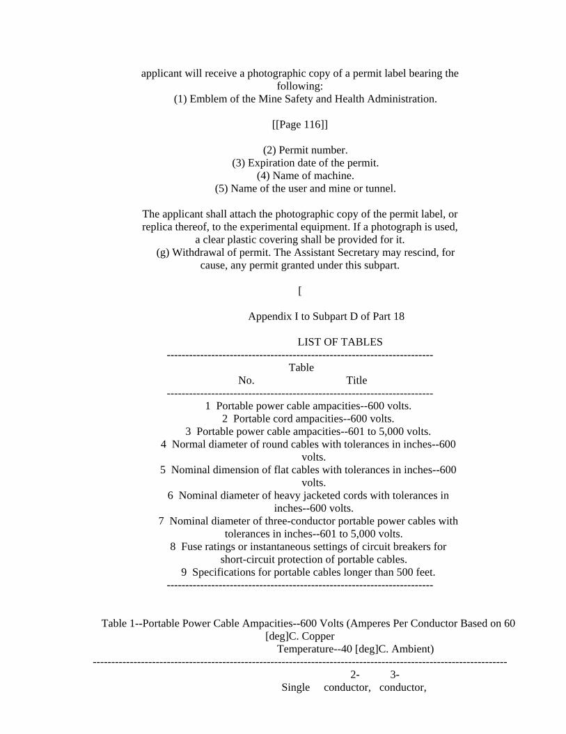
applicant will receive a photographic copy of a permit label bearing the following:
(1) Emblem of the Mine Safety and Health Administration.
[[Page 116]]
(2) Permit number. (3) Expiration date of the permit.
(4) Name of machine. (5) Name of the user and mine or tunnel.
The applicant shall attach the photographic copy of the permit label, or replica thereof, to the experimental equipment. If a photograph is used,
a clear plastic covering shall be provided for it. (g) Withdrawal of permit. The Assistant Secretary may rescind, for
cause, any permit granted under this subpart. [
Appendix I to Subpart D of Part 18
LIST OF TABLES ------------------------------------------------------------------------
Table No. Title
------------------------------------------------------------------------ 1 Portable power cable ampacities--600 volts.
2 Portable cord ampacities--600 volts. 3 Portable power cable ampacities--601 to 5,000 volts.
4 Normal diameter of round cables with tolerances in inches--600 volts.
5 Nominal dimension of flat cables with tolerances in inches--600 volts.
6 Nominal diameter of heavy jacketed cords with tolerances in inches--600 volts.
7 Nominal diameter of three-conductor portable power cables with tolerances in inches--601 to 5,000 volts.
8 Fuse ratings or instantaneous settings of circuit breakers for short-circuit protection of portable cables.
9 Specifications for portable cables longer than 500 feet. ------------------------------------------------------------------------
Table 1--Portable Power Cable Ampacities--600 Volts (Amperes Per Conductor Based on 60 [deg]C. Copper
Temperature--40 [deg]C. Ambient) ----------------------------------------------------------------------------------------------------------------
2- 3- Single conductor, conductor,

Conductor size--AWG or MCM conductor round or round or 4-conductor 5-conductor 6-conductor
flat flat ----------------------------------------------------------------------------------------------------------------
8................................. 45 40 35 30 25 20 6................................. 60 50 50 40 35 30 4................................. 85 70 65 55 45 35 3................................. 95 80 75 65 55 45 2................................. 110 95 90 75 65 55
1................................. 130 110 100 85 75 65 1/0............................... 150 130 120 100 90 80 2/0............................... 175 150 135 115 105 95 3/0............................... 205 175 155 130 120 110 4/0............................... 235 200 180 150 140 130
250............................... 275 220 200 160 ........... ........... 300............................... 305 240 220 175 ........... ........... 350............................... 345 240 235 190 ........... ........... 400............................... 375 280 250 200 ........... ........... 450............................... 400 300 270 215 ........... ........... 500............................... 425 320 290 230 ........... ...........
----------------------------------------------------------------------------------------------------------------
Table 2--Portable Cord Ampacities--600 Volts (Amperes Per Conductor Based on 60 [deg]C. Copper Temperature--40
[deg]C. Ambient) ----------------------------------------------------------------------------------------------------------------
Conductor size--AWG 1-3 conductor 4-6 conductor 7-9 conductor ----------------------------------------------------------------------------------------------------------------
14......................................... 15 12 8 12......................................... 20 16 11 10......................................... 25 20 14
----------------------------------------------------------------------------------------------------------------
Table 3--Portable Power Cable Ampacities--601 to 5,000 Volts (Amperes Per Conductor Based on 75 [deg]C. Copper
Temperature--40 [deg]C. Ambient) ---------------------------------------------------------------------------------------------------------------- 3-conductor types G-GC and SIIC-GC 3-conductor type SHD-GC
2,001-5,000 Conductor size--AWG or MCM 2,000 volts volts
---------------------------------------------------------------------------------------------------------------- 6............................. 65 65 4............................. 85 85
3............................. 100 100 2............................. 115 115 1............................. 130 130

[[Page 117]]
1/0........................... 145 145 2/0........................... 170 170 3/0........................... 195 195 4/0........................... 220 220 250........................... 245 245 300........................... 275 275 350........................... 305 305
----------------------------------------------------------------------------------------------------------------
Table 4--Nominal Diameters of Round Cables With Tolerances in Inches--600 Volts
--------------------------------------------------------------------------------------------------------------------------------------------------------
2-conductor 3-conductor 6-conductor
------------------------------------------------------- -------------------
Type 4-conductor-- 5-conductor-- Conductor size--AWG or MCM Single Types W Type Type Type PCG, 3
Types W & G Types W & G conductor & G PG, 2 PCG, 3 Types W PG, 3 power, 2
Type w Tolerance twisted power power, & G power, control,
ground ground ground ---------------------------------------------------------------------------------------------------------------------
----------------------------------- 8............................. 0.44 0.81 0.84 0.94 0.91 0.93 1.03 0.99 1.07
1.18 <plus-
minus<ls- t0.03 6............................. .51 .93 .93 .98 1.01 1.03 1.18 1.10 1.21
1.31 <plus-
minus<ls- t.03 4............................. .57 1.08 1.08 1.10 1.17 1.20 1.29 1.27 1.40
1.52 <plus-
minus<ls- t.03 3............................. .63 1.17 1.17 1.20 1.24 1.27 1.31 1.34 1.48
1.61 <plus-
minus<ls-
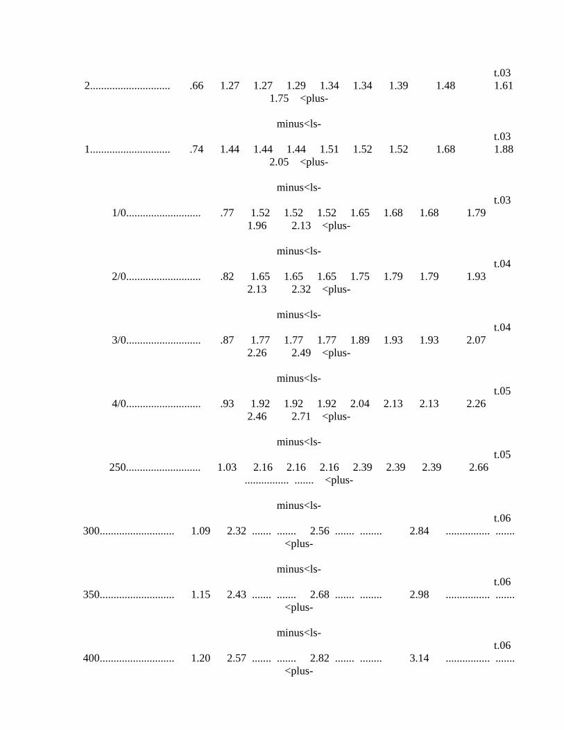
t.03 2............................. .66 1.27 1.27 1.29 1.34 1.34 1.39 1.48 1.61
1.75 <plus-
minus<ls- t.03 1............................. .74 1.44 1.44 1.44 1.51 1.52 1.52 1.68 1.88
2.05 <plus-
minus<ls- t.03
1/0........................... .77 1.52 1.52 1.52 1.65 1.68 1.68 1.79 1.96 2.13 <plus-
minus<ls-
t.04 2/0........................... .82 1.65 1.65 1.65 1.75 1.79 1.79 1.93
2.13 2.32 <plus-
minus<ls- t.04
3/0........................... .87 1.77 1.77 1.77 1.89 1.93 1.93 2.07 2.26 2.49 <plus-
minus<ls-
t.05 4/0........................... .93 1.92 1.92 1.92 2.04 2.13 2.13 2.26
2.46 2.71 <plus-
minus<ls- t.05
250........................... 1.03 2.16 2.16 2.16 2.39 2.39 2.39 2.66 ................ ....... <plus-
minus<ls-
t.06 300........................... 1.09 2.32 ....... ....... 2.56 ....... ........ 2.84 ................ .......
<plus-
minus<ls- t.06
350........................... 1.15 2.43 ....... ....... 2.68 ....... ........ 2.98 ................ ....... <plus-
minus<ls-
t.06 400........................... 1.20 2.57 ....... ....... 2.82 ....... ........ 3.14 ................ .......
<plus-
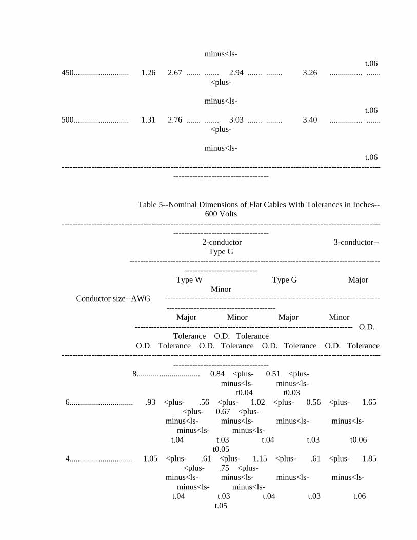
minus<ls- t.06
450........................... 1.26 2.67 ....... ....... 2.94 ....... ........ 3.26 ................ ....... <plus-
minus<ls-
t.06 500........................... 1.31 2.76 ....... ....... 3.03 ....... ........ 3.40 ................ .......
<plus-
minus<ls- t.06
--------------------------------------------------------------------------------------------------------------------------------------------------------
Table 5--Nominal Dimensions of Flat Cables With Tolerances in Inches--600 Volts
--------------------------------------------------------------------------------------------------------------------------------------------------------
2-conductor 3-conductor--Type G
-----------------------------------------------------------------------------------------------------------------------
Type W Type G Major Minor
Conductor size--AWG -----------------------------------------------------------------------------------------------------------------------
Major Minor Major Minor -------------------------------------------------------------------------------- O.D.
Tolerance O.D. Tolerance O.D. Tolerance O.D. Tolerance O.D. Tolerance O.D. Tolerance ---------------------------------------------------------------------------------------------------------------------
----------------------------------- 8............................... 0.84 <plus- 0.51 <plus- minus<ls- minus<ls-
t0.04 t0.03 6............................... .93 <plus- .56 <plus- 1.02 <plus- 0.56 <plus- 1.65
<plus- 0.67 <plus- minus<ls- minus<ls- minus<ls- minus<ls-
minus<ls- minus<ls- t.04 t.03 t.04 t.03 t0.06
t0.05 4............................... 1.05 <plus- .61 <plus- 1.15 <plus- .61 <plus- 1.85
<plus- .75 <plus- minus<ls- minus<ls- minus<ls- minus<ls-
minus<ls- minus<ls- t.04 t.03 t.04 t.03 t.06
t.05

3............................... 1.14 <plus- .68 <plus- 1.26 <plus- .68 <plus- 1.99 <plus- .77 <plus-
minus<ls- minus<ls- minus<ls- minus<ls- minus<ls- minus<ls-
t.04 t.03 t.04 t.03 t.06 t.05
2............................... 1.24 <plus- .73 <plus- 1.35 <plus- .73 <plus- 2.10 <plus- .81 <plus-
minus<ls- minus<ls- minus<ls- minus<ls- minus<ls- minus<ls-
t.04 t.03 t.04 t.06 t.06 t.05
1............................... 1.40 <plus- .81 <plus- 1.55 <plus- .81 <plus- 2.43 <plus- .97 <plus-
minus<ls- minus<ls- minus<ls- minus<ls- minus<ls- minus<ls-
t.04 t.03 t.04 t.03 t.06 t.05
1/0............................. 1.51 <plus- .93 <plus- 1.67 <plus- .93 <plus- minus<ls- minus<ls- minus<ls- minus<ls-
t.04 t.03 t.04 t.03 2/0............................. 1.63 <plus- .99 <plus- 1.85 <plus- .99 <plus- minus<ls- minus<ls- minus<ls- minus<ls-
t.04 t.03 t.04 t.03 3/0............................. 1.77 <plus- 1.03 <plus- 2.00 <plus- 1.03 <plus- minus<ls- minus<ls- minus<ls- minus<ls-
t.04 t.03 t.04 t.03 4/0............................. 1.89 <plus- 1.10 <plus- 2.10 <plus- 1.10 <plus- minus<ls- minus<ls- minus<ls- minus<ls-
t.04 t.03 t.04 t.03 ---------------------------------------------------------------------------------------------------------------------
-----------------------------------
Table 6--Nominal Diameters of Heavy Jacketed Cords With Tolerances In Inches--600 Volts
------------------------------------------------------------------------------------------------------------------------------------------------------------------------------------------------
2-conductor 3-conductor 4-conductor 5-conductor 6-conductor 7-conductor
Conductor size--AWG -----------------------------------------------------------------------------------------------------------------------------
Diameter Tolerance Diameter Tolerance Diameter Tolerance Diameter Tolerance Diameter Tolerance Diameter Tolerance
------------------------------------------------------------------------------------------------------------------------------------------------------------------------------------------------
14................................................................ 0.64 <plus- 0.67 <plus- 0.71 <plus- 0.78 <plus- 0.83 <plus- 0.89 <plus-
minus<ls- minus<ls- minus<ls-
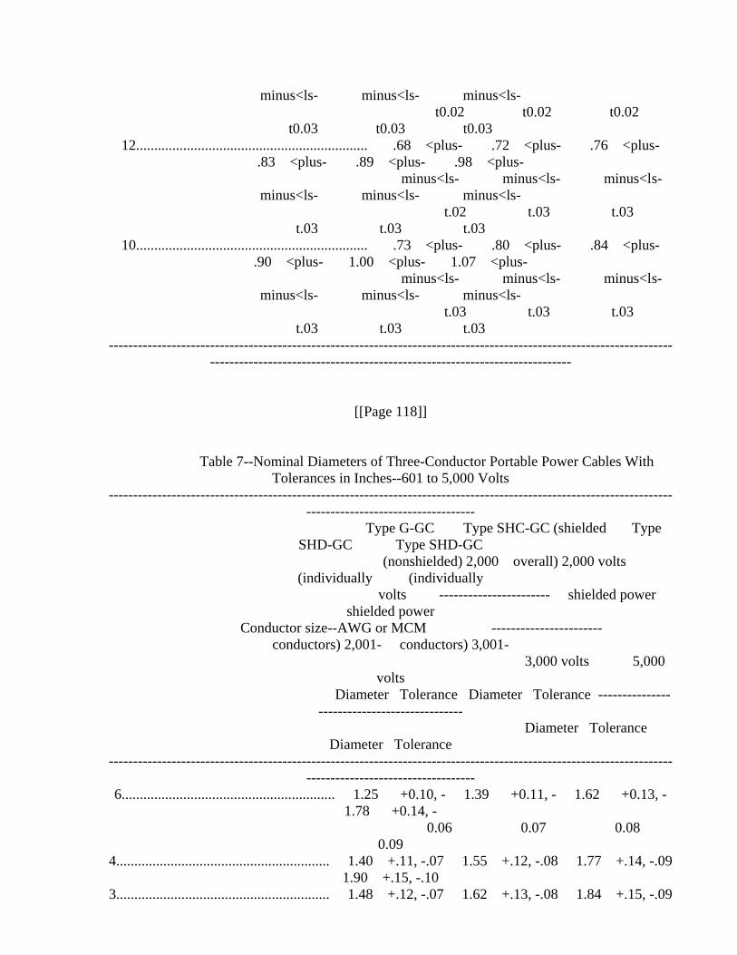
minus<ls- minus<ls- minus<ls- t0.02 t0.02 t0.02
t0.03 t0.03 t0.03 12................................................................ .68 <plus- .72 <plus- .76 <plus-
.83 <plus- .89 <plus- .98 <plus- minus<ls- minus<ls- minus<ls-
minus<ls- minus<ls- minus<ls- t.02 t.03 t.03
t.03 t.03 t.03 10................................................................ .73 <plus- .80 <plus- .84 <plus-
.90 <plus- 1.00 <plus- 1.07 <plus- minus<ls- minus<ls- minus<ls-
minus<ls- minus<ls- minus<ls- t.03 t.03 t.03
t.03 t.03 t.03 ---------------------------------------------------------------------------------------------------------------------
---------------------------------------------------------------------------
[[Page 118]]
Table 7--Nominal Diameters of Three-Conductor Portable Power Cables With Tolerances in Inches--601 to 5,000 Volts
--------------------------------------------------------------------------------------------------------------------------------------------------------
Type G-GC Type SHC-GC (shielded Type SHD-GC Type SHD-GC
(nonshielded) 2,000 overall) 2,000 volts (individually (individually
volts ----------------------- shielded power shielded power
Conductor size--AWG or MCM ----------------------- conductors) 2,001- conductors) 3,001-
3,000 volts 5,000 volts
Diameter Tolerance Diameter Tolerance ---------------------------------------------
Diameter Tolerance Diameter Tolerance
--------------------------------------------------------------------------------------------------------------------------------------------------------
6........................................................... 1.25 +0.10, - 1.39 +0.11, - 1.62 +0.13, - 1.78 +0.14, -
0.06 0.07 0.08 0.09
4........................................................... 1.40 +.11, -.07 1.55 +.12, -.08 1.77 +.14, -.09 1.90 +.15, -.10
3........................................................... 1.48 +.12, -.07 1.62 +.13, -.08 1.84 +.15, -.09

1.98 +.16, -.10 2........................................................... 1.55 +.12, -.08 1.71 +.14, -.09 1.92 +.15, -.10
2.09 +.17, -.11 1........................................................... 1.74 +.14, -.09 1.89 +.15, -.09 2.04 +.16, -.10
2.18 +.17, -.11 1/0......................................................... 1.84 +.15, -.09 2.02 +.16, -.10 2.18 +.17, -
.11 2.34 +.19, -.12 2/0......................................................... 1.99 +.16, -.10 2.16 +.17, -.11 2.29 +.18, -
.12 2.46 +.20, -.12 3/0......................................................... 2.12 +.17, -.11 2.30 +.18, -.11 2.45 +.20, -
.12 2.62 +.21, -.13 4/0......................................................... 2.30 +.18, -.12 2.48 +.20, -.12 2.62 +.21, -
.13 2.76 +.22, -.14 250......................................................... 2.46 +.20, -.12 2.70 +.22, -.13 ........ ...........
........ ........... 300......................................................... 2.63 +.21, -.13 2.84 +.23, -.14 ........ ...........
........ ........... 350......................................................... 2.75 +.22, -.14 2.97 +.24, -.15 ........ ...........
........ ........... ---------------------------------------------------------------------------------------------------------------------
-----------------------------------
Table 8--Fuse Ratings or Instantaneous Setting of Circuit Breakers for Short-Circuit Protection of Portable Cables and Cords
--------------------------------------------------------------------------------------------------------------------------------------------------------
Maximum allowable circuit
Conductor size--AWG or MCM Ohms/1,000 ft. at 25 [deg]C. Maximum allowable fuse breaker instantaneous
rating (amperes) setting (amperes) \1\
--------------------------------------------------------------------------------------------------------------------------------------------------------
14............................................................ 2.62 20 50
12............................................................ 1.65 30 75
10............................................................ 1.04 40 150
8............................................................. .654 80 200
6............................................................. .410 100 300
4............................................................. .259 200 500
3............................................................. .205 250 600

2............................................................. .162 300 800
1............................................................. .129 375 1,000
1/0........................................................... .102 500 1,250
2/0........................................................... .081 ............................ 1,500
3/0........................................................... .064 ............................ 2,000
4/0........................................................... .051 ............................ 2,500
250........................................................... .043 ............................ 2,500
300........................................................... .036 ............................ 2,500
350........................................................... .031 ............................ 2,500
400........................................................... .027 ............................ 2,500
450........................................................... .024 ............................ 2,500
500........................................................... .022 ............................ 2,500
--------------------------------------------------------------------------------------------------------------------------------------------------------
\1\ Higher circuit-breaker settings may be permitted for special applications when justified.
Table 9--Specifications for Portable Cables Longer Than 500 Feet \1\ ---------------------------------------------------------------------------------------------------------------------
----------------------------------- Normal ampacity at 60
Conductor size--AWG or MCM Max. allowable length (feet) [deg]C. copper temperature Resistance at 60 [deg]C.
(40 [deg]C. ambient) copper temperature (ohms)
--------------------------------------------------------------------------------------------------------------------------------------------------------
6............................................................. 550 50 0.512
4............................................................. 600 70 .353
3............................................................. 650 80 .302
2............................................................. 700 95 .258
1............................................................. 750 110 .220

1/0........................................................... 800 130 .185
2/0........................................................... 850 150 .157
3/0........................................................... 900 175 .130
4/0........................................................... 1,000 200 .116
250........................................................... 1,000 220 .098
300........................................................... 1,000 240 .082
350........................................................... 1,000 260 .070
400........................................................... 1,000 280 .061
450........................................................... 1,000 300 .054
[[Page 119]]
500........................................................... 1,000 320 .050
--------------------------------------------------------------------------------------------------------------------------------------------------------
\1\ Fuses shall not be used for short-circuit protection of these cables. Circuit breakers shall be used with the instantaneous trip settings not to
exceed the values given in Table 8.
[33 FR 4660, Mar. 19, 1968; 33 FR 6345, Apr. 26, 1968, as amended at 42 FR 8373, Feb. 10, 1977]
Appendix II to Subpart D of Part 18
LIST OF FIGURES
------------------------------------------------------------------------ Figure
No. Title ------------------------------------------------------------------------
1 Typical layout drawing of a machine. 2 Sample bill of material (to accompany layout drawing shown on
figure 1) 3 Material to be included with the operating instructions on or
with the wiring diagram submitted to each customer. 4 Sample factory inspection form.
5 Typical plane joint. 6 Typical combination joint.

7 Typical threaded joint. 8 Typical threaded straight stuffing box and packing gland lead
entrance with provision for hose conduit. 9 Typical slip-fit straight-type and angle-type stuffing box and
packing gland lead entrance. 10 Typical slip-fit angle-type stuffing box and packing gland lead
entrance and typical plug for spare lead entrance hole. ------------------------------------------------------------------------
[GRAPHIC] [TIFF OMITTED] TC22OC91.024
[[Page 120]]
Figure 2--Sample Bill of Material
B. of M. No. -------- Date ------------
Revision Date 1. ------------ 2. ------------ 3. ------------ 4. ------------ 5. ------------
Bill of Material (Electrical)
(Manufacturing Company)
Model:__________________________________________________________________ (Unit Name)
Approval 2G-____________________________________________________________ Motor:__________________________________________________________________
(Manufacturing Company) Frame___________________________________________________________________
------ Hp., ------ Volts, ------ Ph., ------ Cy., ------ R.P.M.
X/P--------------------(Date). ------------(Date) Extension.
Starter:________________________________________________________________ (Manufacturing Company)
Model___________________________________________________________________ --------Hp., --------Volts.
X/P_____________________________________________________________________ (Date)
------------ Extension. (Date)
Cable--Motor to Starter:

Cond. No. ------, ------<gr-thn-eq> O.D., ------[foot] Long
Hose--Motor to Starter Cable: ------<gr-thn-eq> I.D., ------<gr-thn-eq> O.D., ------ [foot] Long
Portable (Trailing) Cable-- Type:___________________________________________________________________
Cond. No. ------, ------<gr-thn-eq> O.D., ------[foot] Long Hose--for Portable Cable:
------<gr-thn-eq> I.D., ------<gr-thn-eq> O.D., ------[foot] Long Hose Clamps--
2 for Motor-Starter Hose conduit ------<gr-thn-eq> D 1 for Portable Cable Hose conduit ----<gr-thn-eq> D*
*Only when short length of hose is used. Trolley Tap--
(Manufacturing Company) Model ---------------------------- with -------ampere fuse.
Rail Clamps, 2. 1 Ground Clamp, Cat. No. ------
(Manufacturing Company)
1 Return Power Conductor, Cat. No. ------
(Manufacturing Company) or--as Optional
Plug on outby end of potable cable for insertion into receptacle on distribution box or equivalent with short-circuit protective device set
at ------ amperes. Static-free Belt
Model Style
Catalog No. ------,
(Manufacturing Company) Guard for Belt--
Material________________________________________________________________
[[Page 121]]
Overall Dimensions ------<gr-thn-eq> Long x ------<gr-thn-eq> Wide x------<gr-thn-eq> High
Note: The foregoing is intended as a guide. Additional electrical components used shall be completely identified.
Figure 3--Material To Be Included With the Operating Instructions--on or
With the Wiring Diagram Submitted to Each Customer
(Sometimes referred to as ``Caution Statement'')

caution
To retain ``permissibility'' of this equipment the following
conditions shall be satisfied: 1. General safety. Frequent inspection shall be made. All electrical parts, including the portable cable and wiring, shall be kept in a safe
condition. There shall be no openings into the casings of the electrical parts. A permissible distribution box shall be used for connection to the power circuit unless connection is made in fresh intake air. To maintain the overload protection on direct-current machines, the
ungrounded conductor of the portable cable shall be connected to the proper terminal. The machine frame shall be effectively grounded. The power wires shall not be used for grounding except in conjunction with diode(s) or equivalent. The operating voltage should match the voltage
rating of the motor(s). 2. Servicing. Explosion-proof enclosures shall be restored to the state of original safety with respect to all flame arresting paths, lead
entrances, etc., following disassembly for repair or rebuilding, whether by the owner or an independent shop.
3. Fastenings. All bolts, nuts, screws, and other means of fastening, and also threaded covers, shall be in place, properly
tightened and secured. 4. Renewals and repairs. Inspections, repairs, or renewals of electrical parts shall not be made unless the portable cable is
disconnected from the circuit furnishing power, and the cable shall not be connected again until all parts are properly reassembled. Special
care shall be taken in making renewals or repairs. Leave no parts off. Use replacement parts exactly like those furnished by the manufacturer.
When any lead entrance is disturbed, the original leads or exact duplicates thereof shall be used and stuffing boxes shall be repacked in
the approved manner. 5. Cable requirements. A flame-resistant portable cable bearing a MSHA assigned identification number, adequately protected by an
automatic circuit-interrupting device shall be used. Special care shall be taken in handling the cable to guard against mechanical injury and
wear. Splices in portable cables shall be made in a workmanlike manner, mechanically strong, and well insulated. Not more than five temporary
splices are permitted in a portable cable regardless of length. Connections and wiring to the outby end of the cable shall be in
accordance with recognized standards of safety.
Figure 4--Sample Factory Inspection Form
Date ------------ Inspector ------------------------
machine

Designation:____________________________________________________________ Type: ------------ Serial No.___________________________________________
motor
Manufacturer:___________________________________________________________
Serial No.: ------ Type:________________________________________________ Frame:__________________________________________________________________
Hp.---- F.L. Speed:---- Volts:---- Amps.-- Winding: ------ X/P No. ------ (or parts list designation).
starter
Manufacturer:___________________________________________________________
Serial No. ------ Type:_________________________________________________ Hp. ------ Volts: ------ X/P No. ------ (or parts list designation).
Short-circuit protection ------ amps. Overload-current protection ------ amps.
portable cable
Manufacturer: ---------------------------------- Type: ------------ Conductors: --------------
Length: ------ O.D. ------ MSHA No. --------
[[Page 122]]
Is all wiring around machine adequately protected from mechanical damage?
By hose conduit----------, Troughs______________________________________ Metal tubing ----------, Other__________________________________________ By removal of all sharp corners or edges?_______________________________ Is wiring separated from hydraulic components?__________________________
Is an adequate insulated strain clamp provided for the portable cable?__ Are all packing glands properly packed so that \1/8\-inch clearance
remains between packing nut and stuffing box?___________________________ Are lockwashers (or equivalent) provided for all explosion-proof
enclosure fastenings?___________________________________________________ Are all plane joints securely fastened so that an 0.005-inch feeler gage
cannot be inserted?_____________________________________________________ Are all threaded covers secured?________________________________________
How?____________________________________________________________________ Are all electrical connections secure --------and properly insulated
where necessary?________________________________________________________
Sec. 18.90 Purpose.
The regulations of this subpart E set forth the procedures and
requirements for permissibility which must be met to obtain MSHA field approval of electrically operated machinery used or intended for use in by the last open crosscut of a coal mine which has not been otherwise approved, certified or accepted under the provisions of this part 18, chapter I, title 30, Code of Federal Regulations (Bureau of Mines
Schedule 2G).
Sec. 18.91 Electric equipment for which field approvals will be issued.
(a) Individual field approvals will be issued by MSHA under the
provisions of this subpart E for electrically operated machines commercially built, or constructed, by the owner-coal mine operator of such machines including any associated electrical equipment, electrical
components, and electrical accessories. (b) Approvals will not be issued under the provisions of this
subpart E for electrically operated mining equipment manufactured or rebuilt primarily for sale or resale to any operator of a coal mine, or
for small electrically operated equipment which consumes less than 2,250 watts of electricity, or for instruments and other small devices which
employ electric power.
Sec. 18.92 Quality of material and design.
(a) Electrically operated machinery approved under the provisions of this subpart E shall be rugged in construction and shall be designed to
facilitate maintenance and inspection. (b) MSHA shall conduct field investigations and, where necessary, field test electric machinery only where such machinery is found to be
constructed of suitable materials and safe for its intended use.
Sec. 18.93 Application for field approval; filing procedures.
(a)(1) Investigation and testing leading to field approval shall be undertaken by MSHA only pursuant to individual written applications for each machine submitted in triplicate on MSHA Form No. 6-1481, by the
owner-coal mine operator of the machine. (2) Except as provided in paragraph (b) of this section, each
application shall be accompanied by appropriate
[[Page 124]]
photographs, drawings, specifications, and descriptions as required under the provisions of Sec. 18.94 and each such application shall be filed with the Coal Mine Health and Safety District Manager for the
District in which such machine will be employed. (b) The Coal Mine Health and Safety District Manager may, upon

receipt of any application filed pursuant to paragraph (a) of this section, waive the requirements of Sec. 18.94 with respect to such application if he determines that the submission of photographs,
drawings, specifications, or descriptions will place an undue financial burden upon the applicant. In the event a waiver is granted in
accordance with this paragraph (b), initial review of the application will be waived and the applicant shall be notified on MSHA Form 6-1481
of such waiver and the date, time, and location at which field inspection of the equipment described in the application will be
conducted. (c) Following receipt of an application filed in accordance with
paragraph (a) of this section, the Coal Mine Health and Safety District Manager shall determine whether the application has been filed in
accordance with Sec. 18.91, and cause the application to be reviewed by a qualified electrical representative to determine compliance with Sec.
18.92: (1) If it is determined on the basis of the application or the data
submitted in accordance with Sec. 18.94 that further consideration of a field approval is warranted under this subpart E or that the machine
appears suitable and safe for its intended use, the Coal Mine Health and Safety District Manager shall advise the applicant in writing that
further investigation and inspection of the machine will be necessary. The notice issued by the Coal Mine Health and Safety District Manager
shall set forth the time and place at which such inspection will be conducted and specify the location and size of any tapped holes required
to be made by the applicant to facilitate the pressure testing of enclosures.
(2) If it is determined on the basis of data submitted in accordance with Sec. 18.94 that the applicant is not qualified to receive an
approval or that the machine does not appear to be suitable and safe for its intended use, the Coal Mine Health and Safety District Manager shall
so advise the applicant in writing, setting forth the reasons for his denial of the application, and where applicable, the deficiencies in the
machine which rendered it unsuitable or unsafe for use. (3) Rejected applications, together with attached photographs,
drawings, specifications and descriptions shall be forwarded by the Coal Mine Health and Safety District Manager to Approval and Certification Center which shall record all pertinent data with respect to the machine
for which field approval was sought.
[33 FR 4660, Mar. 19, 1968, as amended at 43 FR 12314, Mar. 24, 1978]
Sec. 18.94 Application for field approval; contents of application.
(a) Each application for field approval shall, except as provided in Sec. 18.93(b), include the following information with respect to the
electrically operated machine for which field approval is sought: (1) The trade name and the certification number or other means of
identifying any explosion-proof compartment or intrinsically-safe

component installed on the machine for which a prior approval or certification has been issued under the provisions of Bureau of Mines
Schedules 2D, 2E, 2F, or 2G. (2) The trade name and the flame-resistance acceptance or approval
number of any cable, cord, hose, or conveyor belt installed on the machine for which prior acceptance or approval by MSHA has been issued.
(b) Each application for field approval shall be accompanied by: (1) If the machine is constructed or assembled entirely from
components which have been certified or removed from machines approved under Bureau of Mines Schedule 2D, 2E, 2F, or 2G, photographs or a single layout drawing which clearly depicts and identifies each of the
permissible components and its location on the machine. (2) If the machine contains one or more components required to be permissible which has not been approved or certified under Bureau of
Mines Schedule 2D, 2E, 2F, or 2G, a single layout drawing which clearly identifies all
[[Page 125]]
of the components from which it was assembled.
(3) All applications shall include specifications for: (i) Overcurrent protection of motors;
(ii) All wiring between components, including mechanical protection such as hose conduit and clamps;
(iii) Portable trailing cable for use with the machine, including the type, length, diameter, and number and size of conductors;
(iv) Insulated strain clamp for machine end of portable trailing cable;
(v) Short-circuit protection to be provided at outby end of portable trailing cable.
[33 FR 4660, Mar. 19, 1968, as amended at 57 FR 61223, Dec. 23, 1992]
Sec. 18.95 Approval of machines constructed of components approved,
accepted or certified under Bureau of Mines Schedule 2D, 2E, 2F, or 2G.
Machines for which field approval is sought which are constructed
entirely from properly identified components that have been investigated and accepted or certified for applications on approved machines under
the Bureau of Mines Schedule 2D, 2E, 2F, or 2G, shall be approved following a determination by the electrical representative that the
construction of the entire machine is permissible and conforms to the data submitted in accordance with Sec. 18.94.
Sec. 18.96 Preparation of machines for inspection; requirements.
(a) Upon receipt of written notice from the Health and Safety District Manager of the time and place at which a field approval
investigation will be conducted with respect to any machine, the applicant will prepare the machine for inspection in the following
manner: (1) The machine shall be in fresh air out by the last open crosscut
and free from obstructions, or, if the machine is located on the surface, moved to a clear area;
(2) All enclosure covers shall be removed; (3) The flanges and interior of each enclosure, including the cover,
shall be cleaned thoroughly; (4) All hoses, cables, cord, and conveyor belts shall be wiped clean
to expose surface markings; (5) All electrical components shall be cleaned to reveal all
stampings, identification plates, certification numbers, or explosion test markings.
Sec. 18.97 Inspection of machines; minimum requirements.
(a) Except as provided in Sec. 18.95, all machines approved under
the provisions of this subpart E shall, where practicable, meet the minimum design and performance requirements set forth in subpart B of
this part 18 and, where necessary, the requirements of Sec. 18.98. (b) The inspection of each machine shall be conducted by an
electrical representative and such inspection shall include: (1) Examination of all electrical components for materials,
workmanship, design, and construction; (2) Examination of all components of the machine which have been
approved or certified under Bureau of Mines Schedule 2D, 2E, 2F, or 2G to determine whether such components have been maintained in permissible
conditions; (3) Comparison of the location of components on the machine with the
drawings or photographs submitted to determine that each of them is properly located, identified and marked;
(4) Pressure testing of explosion-proof compartments, when necessary, shall be conducted in accordance with Sec. 18.98; and:
(i) Where the results of pressure testing are acceptable, the applicant shall be advised;
(ii) Where the explosion-proof enclosure is found unacceptable, the applicant shall be so informed;
(iii) If the performance of the explosion-proof enclosure is questionable, the qualified electrical representative may, at the
request of the applicant, conduct a further detailed examination of the enclosure after disassembly and record his additional findings on MSHA
Form No. 6-1481 under Results of Field Inspections.
[33 FR 4660, Mar. 19, 1968, as amended at 42 FR 8373, Feb. 10, 1977]
[[Page 126]]
Sec. 18.98 Enclosures, joints, and fastenings; pressure testing.
(a) Cast or welded enclosures shall be designed to withstand a
minimum internal pressure of 150 pounds per square inch (gage). Castings shall be free from blowholes.
(b) Pneumatic field testing of explosion-proof enclosures shall be conducted by determining:
(1) Leak performance with a peak dynamic or static pressure of 150 pounds per square inch (gage); or
(2) A pressure rise and rate of decay consistent with unyielding components during a pressure-time history as derived from a series of
oscillograms. (c) Welded joints forming an enclosure shall have continuous
gastight welds.
Sec. 18.99 Notice of approval or disapproval; letters of approval and approval plates.
Upon completion of each inspection conducted in accordance with Sec. 18.97(b), the electrical representative conducting such inspection
shall record his findings with respect to the machine examined on MSHA Form No. 6-1481 together with his recommendation of approval or
disapproval of the machine. (a) If the qualified electrical representative recommends field
approval of the machine, the Coal Mine Health and Safety District Manager shall forward the completed application form together with all
attached photographs, drawings, specifications, and descriptions to Approval and Certification Center. Approval and Certification Center
shall record all pertinent data with respect to such machine, issue a letter of approval with a copy to the Coal Mine Health and Safety
District Manager who authorized its issuance and send the field approval plate to the applicant. The approval plate shall be affixed to the
machine by the applicant in such a manner so as not to impair its explosion-proof characteristics.
(b) If the electrical representative recommends disapproval of the machine, he shall record the reasons for such disapproval and the Coal Mine Health and Safety District Manager shall forward the completed application form and other data to Approval and Certification Center which shall record all pertinent data with respect to such machine and notify the applicant that the application for approval has been rejected
and the reasons for the rejection.
[33 FR 4660, Mar. 19, 1968, as amended at 42 FR 8373, Feb. 10, 1977; 43 FR 12314, Mar. 24, 1978]