the project - bridge overpass, chesapeake, virginia project - bridge overpass, chesapeake, virginia...
TRANSCRIPT

5/5/2015
1
Anatomy Of A Bridge FailureGEO3T2 Conference
Raymond A. DeStephen, PEApril 10, 2015
The Project - Bridge Overpass, Chesapeake, Virginia
Four span bridge over RR and highway

5/5/2015
2
Project Completion
Bridge designed in 1987
Construction started Spring 1990
Construction completed by 1992
Project Details
Bridge is 100 ft wide and 250 ft long
Horizontally curved alignment; vertically curved grade with 5% gradients.
Bridge deck super-elevated at 4%
Approach embankments: 35 ft high; 90 ftupper width; 2H:1V slopes
Piers and abutments on 12 inch prestressed, precast concrete piles; 70 and 100 ft long, respectively
5/5/2015
3
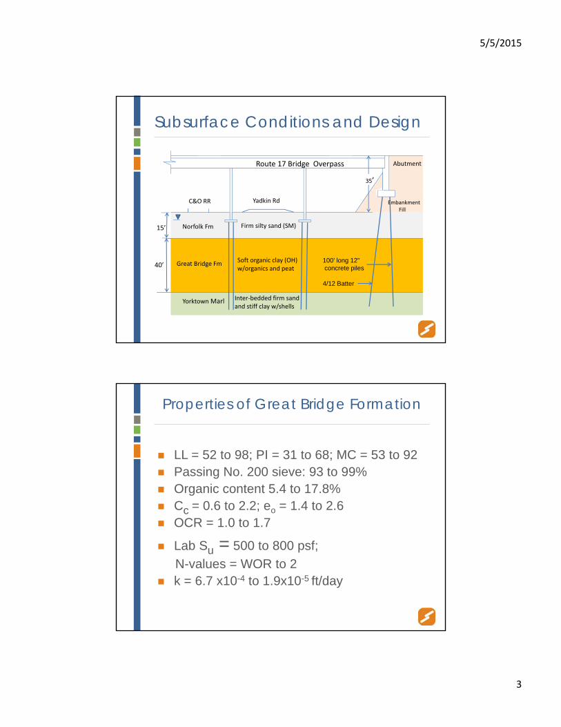
Subsurface Conditions and Design
Yadkin RdC&O RR
Firm silty sand (SM)
Soft organic clay (OH) w/organics and peat
Inter‐bedded firm sand and stiff clay w/shells
Embankment Fill
Route 17 Bridge Overpass
35’
100’ long 12”concrete piles
4/12 Batter
Norfolk Fm
Great Bridge Fm
Yorktown Marl
40’
15’
Abutment
Properties of Great Bridge Formation
LL = 52 to 98; PI = 31 to 68; MC = 53 to 92 Passing No. 200 sieve: 93 to 99% Organic content 5.4 to 17.8% Cc = 0.6 to 2.2; eo = 1.4 to 2.6 OCR = 1.0 to 1.7
Lab Su = 500 to 800 psf;
N-values = WOR to 2 k = 6.7 x10⁻⁴ to 1.9x10⁻⁵ ft/day

5/5/2015
4
PpPp
Preliminary Report Conclusions
Support bridge on 12-inch concrete piles in Yorktown formation sands and clays for an allowable 100 ton capacity.
Note: No mention of allowance for drag load.

5/5/2015
5
Preliminary Report Conclusions
“Embankment settlements of 2.5 to 3.5 ft are predicted”.
“While the time required for the total completion of primary settlement is in years, 80% is likely to occur in the first 3 months”.
“Typically in non-homogenous clays with potential sand lenses, settlement rates in the field are usually faster than predicted”.
“It may be possible to accelerate settlement by installing wick drains…”
80%
3 mos
Estimated Time of Embankment Settlement
Time (days)
Settl
emen
t (Ft
)

5/5/2015
6
Preliminary Report Conclusions
“Consolidation testing indicates sampling procedures are disturbing the soil… recommend in situ testing”.
“Based on prototype test berm…settlements based on dilatometer results were significantly more accurate than those predicted by classical consolidation tests…those settlements were also substantially smaller.”
Preliminary Report Conclusions
“Since the time required to complete the predicted settlements is critical to the
construction schedule, we recommend that the approach embankments be instrumented to
evaluate actual settlements, pore water pressure distribution and stability.”
5/5/2015
7
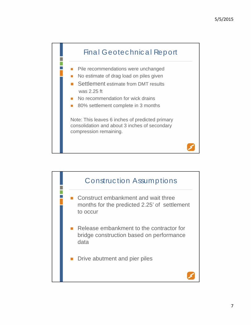
Final Geotechnical Report
Pile recommendations were unchanged
No estimate of drag load on piles given
Settlement estimate from DMT results
was 2.25 ft
No recommendation for wick drains
80% settlement complete in 3 months
Note: This leaves 6 inches of predicted primary consolidation and about 3 inches of secondary compression remaining.
Construction Assumptions
Construct embankment and wait three months for the predicted 2.25’ of settlement to occur
Release embankment to the contractor for bridge construction based on performance data
Drive abutment and pier piles

5/5/2015
8
The Designer Has a Question
What about drag load?
Answer - 15 to 20 tons
Amendment No. 1 issued by the geotechnical consultant - “drive piles an additional 10 feet to account for any drag load”
Pile Installation
Final pile resistances were highly variable
Some >100 blows/ft and some < 40 blows/ftdepending on bearing on clay or sand
Final tip grades varied by 22 ft
All pile inspection was done by the Owner

5/5/2015
9
Instrumentation Program Was Impressive
Ten settlement plates
Three piezometers
Four vertical slope indicators
Two horizontal settlement profile indicators
Field Data – Horizontal Indicator

5/5/2015
10
Pore Pressures in Organic Clay Layer
Pore pressure dissipationonly about 30% three monthsafter embankment completion(not 80%)
40’
Semi-log Plot of a Typical LaboratoryConsolidation Time Curve

5/5/2015
11
Field Data - Arithmetic Time-Settlement Plot Of Embankment
EmbankmentsReleased
Semi-log Plot of EmbankmentTime-Settlement Data

5/5/2015
12
Conclusions from the “Report of Embankment Instrumentation”
“Horizontal indicators indicate that the (vertical) settlement is still occurring”.
“Horizontal movement continues…may still be experiencing plastic flow”.
“While pore water pressures have reduced, values indicate consolidation is still occurring”.
“Construction of the overpass bridge and pier foundations can proceed”.
Early Problems
Jan 1992 City noted that “approach grades were lower than bridge grades”
Final inspection May 1992 – no major deficiencies were noted
Dec 1996 - additional 11 inches of settlement noted
By May 2000 – Additional embankment settlements were 2.5 to 3 ft!
(Note: Total of 5 to 5.5 ft since construction began).

5/5/2015
13
2003 Schnabel Study Results
Post construction approach settlements are
up to 3 ft
Organic clay is consolidated 75 to 95% near the top of the layer and 55 to 75% in the middle.
Strength gain of about 50% has occurred due to consolidation
Depressed sidewalk and guardrail
VISUAL DAMAGE

5/5/2015
14
Vertical crack onbeam web abovebearing plate
Diagonal Stress Crack in Under Beam

5/5/2015
15
Cracked and Grouted Beam
Rotation of Back Wall
Displacement relativeto girder

5/5/2015
16
Buckling of Slope Protection
Diagonal Crack in Wing Wall
5/5/2015
17
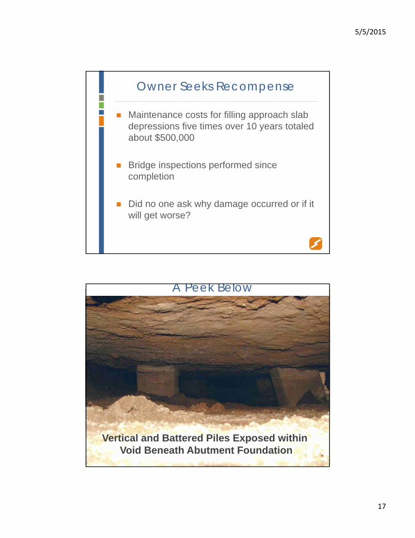
Owner Seeks Recompense
Maintenance costs for filling approach slab depressions five times over 10 years totaled about $500,000
Bridge inspections performed since completion
Did no one ask why damage occurred or if it will get worse?
Void Space Beneath Abutment Foundation
A Peek Below
Vertical and Battered Piles Exposed within Void Beneath Abutment Foundation

5/5/2015
18
Exposed Reinforcing Steel
Concrete Spalled/ Reinforcement Exposed
Pile head within abutment foundation
Remainder of pile has settled with soil.
Tension Failure of Piles due to Negative Drag

5/5/2015
19
You mean they’re………….…gone?
Geotechnical Engineer –peeks under abutment but does not crawl in

5/5/2015
20
Bridge Engineer –Crawling out from under abutment
Contractor Opines on Negative Drag
“I’d always heard you geotechnical guys talk about
negative shaft friction, but I never believed in it until now”.

5/5/2015
21
Dragload
Calculated as 100 to 120 tons (considering strength gain in clay and drag from
overlying sand and embankment fill)
This is 5 to 6 times the original estimate!
Vertical Pile Loads
Working loads 40 to 60 tons
Combined working loads and negative drag loads exceeded the design allowable capacity of 100 tons
For piles bearing in clay the capacities were far exceeded

5/5/2015
22
Post Construction Pile Settlement
Center pier piles: up to 1.5 inches
End pier piles: up to 3.5 inches
Abutment piles: 4 to 12 inches
As expected, pile settlements varied with distance from the approach embankments.
Remedial Alternatives
Underpin with micropiles
Underpin with jet grouting
Partial reconstruction – provide new support for end spans

5/5/2015
23
Final Remedial Design
Reconstruct bridge abutments
Leave piers and bridge spans in place
Do not reuse existing back walls and abutment piles
Use 16” dia. steel pipe piles with 80 ton allowable capacity
Limit future pile drag load to the extent possible
Remedial Design and Testing
Use temporary bent to support span while replacing abutment
Minimize drag load• Case upper 50 ft
• Using pile coatings within clay
Testing during construction• Dynamic testing: initial drive and restrike
• Static testing: Compression test on full length pile
Tension test on cased & coated portion.

5/5/2015
24
Reconstruct Abutment Using Temporary Pier to Support Bridge Deck
Access Holes Cut Through Bridge Deck

5/5/2015
25
Jacking Up End Span
Temporary Shoring
Temporary Pier
New Abutment Pipe Piles

5/5/2015
26
Pile Coatings Applied
Hardened Coatings on Piles

5/5/2015
27
Control Piles being Driven
PDA Testing

5/5/2015
28
Pile Load Test
Contractor Insisting He’s Right In a Robin Hood–Little John Type Standoff

5/5/2015
29
Pullout Test Setup
Shear Failure Appears to be Mostly in Clay

5/5/2015
30
Pile Driving Template
Template With Outer Pipe Sleeves
Pipe pile outersleeves in place
JS1

Slide 60
JS1 This may be a good place to talk about the exploding casing event.Jim Seli, 11/24/2014

5/5/2015
31
Driving Replacement Pipe Piles
Lessons Learned
Using the least conservative method to predict consolidation may not always be the best choice.
If you plot field consolidation data arithmetically you just might come to the wrong conclusion.
You cannot ignore redundant field performance data no matter how bad the news is.
If you inspect a bridge and it seems to be falling apart – you have to ask “why?”

5/5/2015
32
Lessons Learned (continued)
Using pile coatings to reduce pile friction may be dubious, particularly when you’re trying to coat a cylinder.
Don’t argue with a contractor while standing above ground on a narrow beam.
Don’t crawl under failing structures (unless you’re a bridge engineer).
Questions??