the post office electrical engineerst journal
TRANSCRIPT

THE
ELECTRICAL
POST OFFICE
ENGINEERSt JOURNAL Vol. XXVll January, I 9 35 Part 4
A New High-Speed Multi-Channel Carrier Telegraph System
G. T. EVANS and
L. T. ARMAN
T 1-1 E Leafield radio station is situated approximately 15 miles west of Oxford, and comprises ·everal long and short wave medium power
telegraph transmitters for overseas communication. These transmitters are operated from the Central Radio OHice in London by means of a new high-speed Multi-Channel Carrier Telegraph communication system developed in the Department's Radio Section.
Prior to the introduction of the new system, the method of signalling was by means of double- urrent operation on single-wire lines leading from London to each transmitter and the terminal signalling equipment conformed to the usual telegraph practice for such circuits.
Economical utilization-of land lines and the necessity for up-grading the land line portion of radio circuits to provide for developments in radio telegraph technique demanded a system having a performance considerably superior to that hitherto achieved. 1-1 igh-speed telegraphy employing currents in the audio-frequency range in ordinary loaded telephone lines does not become an attracti\'e economical proposition unless the transmission on each channel is restricted to a narrow frequency spectrum. Considerable narro,,·ing of the spectrum for given signalling peed can be attained if special methods are adopted at the receiving end to oITset
Time -
the degradation produced by restricted operation and the limits to which this can be accomplished therefore define the spectrum employed and hence the economics of the system.
It is the purpo e of this article to give a brief description of the new system \\·hich ha the outstanding feature of a wholly electrical method of transmis ion abolishing delicate mechanical adjustments characteristic of telegraph transmission systems hitherto in use, and which enable the speeds of transmission to be raised by effecting an automatic correction to signals distorted by restricted frequency range of transmission.
Tr£111smission Phe11ome11a. When an oscillatory current of a single frequency is started or stopped abruptly, as in sending a dot or a dash from a controlling transmitting key or telegraph relay, there i manifest, momentarily, in an ordinary telephone line a wide continuous spectrum of additional frequencie on each side of the single frequency at the commencement and termination of each impulse. r ow, if the range of this wide band of frequencies is not restricted in some way or other it would be practically impo sible to transmit high-speed signals simultaneously on the several channels since the transient frequencies of the difTcrent transmissions would overlap and could not be physically separated
B. R1·ception of extraneous emi,>ion in adjac1·nt channl'I, 1500-1800 c.p.s. amplilied 22 db. with rc>pecl to A .
. \. Tran-mi,�ion uf approximate rectangular da,h al 1350 c.p.,.
C. R<·et•ption of !'Xlr:11wou� cmi,>ion in adjacf'nt chanrwl, 900-1200 c.p.s. amplifif'd 22 db. \\'ith n•>pecl to A.
I I 8 I I I I • I I I I 8 I I I I • I I I I 8 I D. Timing; 2-milli,<•cond intervals.
Fie;. 1.-EFFECT OF KE\ 1�c; lh.cT.\�Guu11 O;,ctLLATOIH' DA;,11.
V<JL. XXVJJ. p 241

at the Jar end. At the same time, it is very necessary to arrange for the transmission of a certain narrow range of these frequencies situated on each side of the fundamental frequency. For example, at the receiving terminal of a six-channel system, a simple dash sent out at a frequency corresponding to channel 3 will cause dots of a lower intensity to appear in channels 1, 2, 4, 5 and 6. One dash will produce two dots in each channel and, owing to the action of the receiving filters, the oscillation comprising each dot will be approximately at the midband frequency of each of the channels. The oscillagram of Fig. l illustrates a typical case. The delay between the incidence of the dash (curve A) and the appearance of the extraneous emission (curves Band C) is due to the delay time of the channel filters.
On the other hand, a simple dash of the original frequency contained in the rectangular envelope of Fig. 2(a) \vhen keyed through a selective circuit or
FIG. 2.-RECTAKGlJL\I<
AKD ROUNDED DASH.
filter will appear in the '' rounded '' form shown in Fig. 2(b). The selective circuit has a lag which stops the signal from reaching its full amplitude immediately, and also prevents its immediate cessation when the key is opened. The faster the rate of signalling, or the
narrower the range of frequency selectivity, the greater is the relative distortion; for example, if dashes are created too rapidly the signals will not fall to zero though the key may be fully open. Conversely a solitary dot will not rise to its full amplitude. Thus, with high-speed operation the carrier-signals received through selective circuits exhibit much the same idiosyncrasies as is the case with the slower speed submarine cable telegraph using direct current.
While the usual method of restricting the range of transmitted frequencies is to employ a filter in each sending channel before the channels are combined, in the system about to be described simpler and less costly means arc employed to achieve the desired suppression of the unwanted frequencies and to permit the transmission of the \vantcd band.
It would perhaps be more appropriate to say that in this system the unwanted frequencies are not created or are created to a much lesser extent in the first instance. This is rendered possible by the introduction of a new type of keying relay, called the !\Iodulator, \vhich permits the building up and stopping of the oscillatory current in the line to be a relatively gTadual instead of an abrupt process.
The problem of reception of the rounded signals of such varying character has been satisfactorily solved by a thermionic receiving device called the Trigger Relay.1 For a large degradation of the rectangular-shaped envelope of the transmitted signals, caused by the narrowing of the spectrum at
1 Printed Paper, No. 136. l.P.O.E.E. "Some Developments in Telegrnphic Technique as Applied to Rndio Circuits." H. Fnulkner, B.Sc. (Hons.), and G. T. Evans.
242
the sending an<l rece1v111g ends o[ the system, the characteristic performance of this relay causes not only the restoration of the rounded oscillatory impulse to an abrupt direct current of uniform magnitude, but the '' time '' duration of each impulse is restored to its proper relationship with respect to the transmitting end. As distinct from normal met hods of reception this relay introduces a characteristic distortion which is the opposite of that exhibited by the line and selective circuits.
By way of interest it may be mentioned that the amount of compensation introduced to offset transmission distortion is such that undistorted rectangular signals applied at the input pass out of the relay in badly distorted formation unless the compensation is removed.
The operation of the system will be best understood if the foregoing sending and receiving elements, i.e., Modulator and Trigger Relay arc first described.
M adulator. The modulator supersedes the familiar telegraph relay employed to make and break a steady source of oscillatory current. lt is similarly operated by a controlling marking and spacing direct current from the extension line or instrument room. The device, which comprises a small Westinghouse rectifier and input and output transformers, contains no delicate moving mechanical parts or uncertain contact-making mechanism, possesses the important advantage of freedom from bias distortion and, save for normal routine tests, requires no adjustment.
Principles of Operation. The voltage current characteristic of all contact rectifiers is of the. type shown in Fig. 3.
a
c
B APPLIED VOLTAGE
FIG. 3.-FORM OF
VoLT,\GE/(:imRENT
l'll.\RACTEl<ISTIC OF
CONTACT R ECTt FIERS.
c\t or about B the origin of the curve the resistance is very high compared to its value at a point C. If an alternating voltage of small amplitude is applied to such a rectifier operating at B, little or no current is rectified or passed by the device. If, however, the point of operation is moved to C by the application of a direct voltage, the same small alternating voltage will produce an alternating· current component through the rectifier. The application or withdra11al of
the direct voltage thus starts or stops the flm\- of alternating current.
To effect the mutual separation of the direct and continuous current, an assembly of four rectifiers 1n bridge form is used as shown in Fig. 4.
Fw. 4.-BRIDGE AssEMBLY oF KEYING CoNTRoL.

With this arra1'lgc1\\cnt no dircd cllrtcnt flows in the A.G. circuit and conversely no A.G. voltage is
applied to the D.G. circuit in either the key-up or key-down position. The pract ical realization of this scheme is shown in the diagram of Fig. 5.
s,
� •M,ARKING CURRCNT ls •SPACING 11
F1G. 5.- ·c1rnM.1nc l>1.1G1uM OF KEYING MODULATOR.
Input and output transformers are introduced in the alternating current path and the windings are so arranged that in the non-conducting condition of the rectifier the voltage developed across the outer terminals of P2 is zero due to the opposite windings of SI. In the conducting condition of the rectifier,
a
I -
h
c
11111111111111tl111111I111111tl1111tlIIIIII1111111 I
Time -
however, the windings of the transformers becolT\e effectively series aiding.
The direct current actually flowing in the rectifier is a fraction of the current in the control line from the instrument room in order to retain the standard telegraph practice of ± 80-volt signalling.
The action of the device in rounding off the oscillatory impulse is accomplished by the inductance, L, included in the rectifier circuit which prevents the controlling direct current, i, attaining its final value immediately on depressing the sending key but allows it gradually to rise to this value in accordance with the equation
i = : ( 1 - e.- � 1 ) where R is the resistance of the rectifier and associated network. Moreover, the direct current does not suddenly drop to zero from its highest value when the key is opened, but falls in accordance with a similar time function which shapes the end of the signal.
The oscillagrams of Fig. 6 illustrates the action of the Modulator.
Trigger Relay. The trigger relay is a thermionic valve device which receives the rounded oscillatory impulse from each channel and converts it into a
Rectangular dots with inductance out of circuit.
Rounded dots due to insertion of imludance L.
c Controlling O.C. from \.\"lll'at>tonc tran>millcr.
1/ Timing; 2-milli>ccond in ten ab.
13. Reception, a> in Fig. 1 (13), uul with amplification of 90 uli.
A. Trarhmi"ion of ua'h al 1,350 c.p.� . . rounded by modulator.
C. Reception, as in Fig. 1 (C), but with amplification of 40 db.
I I I I • I I I I • I I I I • I ·I I I • I I I I D. Timing; 2-millisecond intervals.
FtG. 6.-0SCILLAGRAMS 11.Ll'STRATING PERFORMANCE OF MODULATOR AND lh:DUCTION OF E;1.T1UNl!OUS EMISSION.
243

larger abrupt direct current impulse which actuates the radio transmitters, monitoring Wheatstone tape recorders, or the order wire sounders.
Fig. 7 shows a simple schematic diagram of the relay.
Rs
FIG. 7.-SCHEMATIC DIAGRAM OF TRIGGER RELAY.
The oscillatory impulse passes through a small full-wave metal rectifier before actual application to the input terminals. This rectifier is, however, omitted from the simple diagram for the sake of clearness.
In the normal condition, i.e., with no signal input, the grid of V 1 is biassed negatively to the no current condition in that valve by virtue of the current through R1; while the grid of V 2 is at zero potential with respect to this cathode, thus permitting maximum current to flow in the output load R5• It is important to observe at this stage that the anode current of V 2 flows through R1•
Now if the potential on the grid of V1 is raised positively as by the arriving signal at the input, current commences to flow in V 1 and R2 thus decreasing the current in V2, R5, and consequently R1• It is seen, therefore, that the grid of V 1 gets a positive bias in addition to, and resulting from, the signal input voltage, and this internal action in the relay continues until the current in R5 is reduced to zero.
With a suitable value for RP a phenomenon of instability termed " triggering " takes place in which the reduction of current in V 2 to zero is virtually instantaneous with the application of the signal voltage above a certain minimum. Again, depending on the circuit constants, the new or triggered condition will obtain so long as the originally applied signal voltage persists. On its withdrawal, a similar phenomenon of triggering in the reverse direction occurs and a reversion to the original or normal state takes place.
D.C. Hysteresis. The behaviour of the mutually coupled circuit of vl and v2 exhibits a form of hysteresis phenomenon. Referring to Fig. 8, if the critical voltage where the discontinuity arises on increase of signal volts is e8, an arbitrary zero datum being chosen, then, on reduction of voltage, the reverse discontinuity will occur at a lower voltage er and the value e8 - er can serve as a measure of the hysteresis loop for the purpose of this discussion. In practice e8 - er can be arranged to be nearly zero.
The point of interest, especially to those experienced .in the art of signalling, is that under dynamic conditions of operation the practical form of this relay is m�d
.e to exhibit a third effect, namely,
that of the add1t1on by the actual input signal of a compensating v?ltage ec to the restoring voltage er so that er + ec IS greater than e8• Now ec does not
244
begin to appear until the initial triggering. action at
the threshold operating value e8 has been effected
and its value is arranged to be dependent on the signal voltage in excess of e8•
It is therefore obvious that the hysteresis loop of
the relay will change from a condition such as (a) in
Fig. 8 for small signal amplitudes to (b) for larger
(a)
0 Er 'Es VOLTS APPLIED TO GRID OF V,
(b)
O E5 Er+Ec VOLTS APPUED TO G,�!Q ;Jf V1
Fm. 8.-0VERALL
CIIA[�i\CTEIHSTICS OF
TRIGGER RELAY.
amplitudes, the width of the loop being dependent on the magnitude of the input signal.
The compensating voltage ec is introduced by the resistance and con-denser Re acting in the grid circuit of V 1• Before the initial triggering takes place, the grid of vl b�ing in the negative condition, the resistance and condenser play no part; but directly the relay is triggered by the input signal, the negative potential
is removed, thereby transferring the grid from the negative condition into the more positive region where grid current will flow.
A proportional voltage will be developed across the resistance condenser Re as the rounded input signal increases in value. By the suitable choice of values the duration of a dot of large amplitude (a), can be made to equal the dot of smaller amplitude (b) as shown in Fig. 9.
L__FY OUTPUT
' I
: (a) I
� I I
Es�
Es�Er
FIG. 9.-TYPICAL EFFECT OF
TRIGGER RELAY IN CoRI<ECTING
SIGKAL DISTORTION.
Description of System. The system provides for twelve outgoing and two incoming channels between London and Leafield; seven channels, six outgoing and one incoming operate per single pair of wires, two such pairs being employed. Ten of the outgoing channels are designed for high - speed operation of the
radio transmitters, while the remaining t\VO outgoing are used in association with the two incoming channels for service order wire communication between the Radio Station and C.R.O. The order wire transmissions in the opposite direction are operated in the same frequency band (although not at the same frequency), discrimination between send-

ing and receiving for the purpose of enabling full duplex working on the order wires being accomplished by differential line transformers at each end. Thus, as regards the connecting line, seven channels are operated in six frequency bands.
Fig. 10 shows in a simple manner the circuits provided.
LONDON C.R.O. '
13' ORDER WIRE 1:
3: 3: 1: g: 11:
HIGH SPEED
4: CHANNELS
.: a:
10: 12, 2:
ORDER WIRE 14l
..J ..J < <( z z ��NEJ__� w w I- I-
i.: i.: > >
-' ..J < f;' z �L---..!::..INE�� w
a:
I- :'.' i.: i.: > I.. >
LEAF I ELD
:
! RADIO TRANS.\ffRS.
�RW!AE� : GIX '
@ill @ill �
� � !ill
:oRDER WIRE
FIG. 10.-CIRCUITS PROVIDED BY HIGH-SPEED
CARRl!lR SYSTEM.
Frequencies and Band ·width of Channels, and Speed of Signalling Frequencies. The frequencies employed for the channels in the two lines are as follows:-
Line 1. Channel 1
Outgoing ,, 3 from ,, 5
London ,, 7 ,, 9 ,, 11
Incoming f to l Channel 13
London \
450 750
1050 1350 1650 1950
300
Line 2. Channel 2 450
,, 4 750 ,, 6 1050 ,, 8 1350 ,, 10 1650 ,, 12 1950
Channel 14 300
Channels 1 and 13 in Line 1 and channels 2 and 14 in Line 2 are employed for the order wire lines between the C.R.0. and Leafield Wireless Station.
Band width. The channels are segregated at the Leafield end by a somewhat unusual system of filters, the net band width allocated for the transmissions being-
Channel 13\ 0 to 600 cycles per second. , , 1 I ,, 3 600 to 900 ,, ,, ,, ,, 5 900 to 1200 ,, , , ,,
,, 7 1200 to 1500 ,, ,, ,, ,, 9 1500 to 1800 ,, ,, ,, ,, 11 1800 to 2100 ,, ,, ,,
Channels No. 14, 2, 4, 6, 8, 10, 12 operating in Line 2 are of course similarly spaced.
Speed of Signalling. The system gives practically distortionless simultaneous transmissions on all channels with a substantial margin of allowable variation in the strength of the received signals up to the following speeds :-
I Channel No.
'
Morse equivalent. Baucls. 1· Speeds per _channel.
-------- ----- - ·- - ------
High speed channels
Order Wire Outgoing
Order 'Wire Ingoing
3 to 12
1 and 2
13 and 14
184 j 230 words per min.
160 1 200
128 i 160 I
Total Morse speed per band width of 2100 c.p.s. is 1500 w.p.m. approx. in each line.
London Terminal (transmitting channels). Fig. 11
shows a block schematic of the London end : the twelve sending channels are fed from six oscillators, each oscillator feeding two channels operating in <lifferent cable pairs. A reserve oscillator, which is capable of pro<lucing singly any of the six working frequencies, is also provided.
The oscillator output is conducted to the channels through a dividing unit known as the oscillator
ID ' '
FIG. 11.-BLOCK SCHEMATIC OF C.R.0. TERMINAL.
245

differential coils. The purpose of this arrangement is to maintain the carrier current in the one channel perfectly steady whilst the current from the same oscillator flowing into the other channel is being started and stopped during the process of signalling. After passing through the unit, a disconnexion or a short-circuit of the current in any one branch output of the differential coils does not influence the flow of current in the complementary branch.
To send a marking signal, the instrument room sends a direct current positive to " A " line which returns via the modulator to earth on the" B." The action of the current is to remove a 11 transmission loss " in the alternating current path through the particular modulator, so that the oscillatory current from the oscillator is released to line. On the removal of the direct current, and also during the application of a reversed or spacing current to the " A " line, the loss is proportionately re-introduced and reaches its final value when the negative current is fully established. In this state of the modulator, the V.F. current through it is attenuated to the low level of the spacing condition at the distant end.
The output of the modulators, each containing the restricted but fresh range of frequencies created in keying, are combined and the whole amplified for transmissions to line by means of the " Send " amplifier. The combining unit consists of a resistance network which, in association with the high impedance input transformer of the amplifier, is designed to reduce the possibility of " cross modulation " at the combining point. This is a phenomenon which occurs in a common transmission path which is not linear, that is, the path carrying the plurality of transmissions does not remain at the same transmission equivalent for different magnitudes of current passing through it. The passage of two or more frequencies through non-linear circuits produces frequencies which may fall in the range of other channels.
When all channels are transmitting signals, the current leaving the amplifier for the line is of the nature of a complex alternating current wave being the result of six contiguous bands of frequencies, the mean frequency of each band being the corresponding osci Ila tor frequency.
An oscillagram of the complex wave containing six transmissions is shown in Fig. 12.
London Terminal (receiving channels). It was stated earlier that the complex current leaving the amplifier flows to line. Before actually entering the line, however, the outgoing transmission traverses the differential transformers or duplexing arrangement. The principle of this arrangement is exactly similar to the line and balance terminating sets of telephone repeatered circuits. The balancing network is not quite so complicated, however, since the balance is only required to be effective over the relatively narrow range of frequencies, viz., 0-600 c.p.s., used for the order wire cirq1its.
The incoming current of 300 c.p.s. from Leafield enters a 0-600 c.p.s. low pass filter and proceeds to the trigger relay, the function of which is to send out a direct current to actuate the telegraph sounder apparatus in the instrument room. The relay is a three-valve unit, the first valve acting as an amplifier element. The other two valves constitute the trigger relay proper.
A photograph of the equipment at the London end is shown in Fig. 13. The apparatus is mounted in units fitted on both sides of two standard racks 10' 6" high. Adequate provision of measuring instruments and facilities for determining the performance of each unit is made and reserves are provided for the more vital units.
Three signalling galvanometers for the purpose of checking the direct current from the control telegraph lines are fitted. These indicate the magnitude of the received marking and spacing currents from the instrument room that pass through the modulator. There is also a sensitive gain measuring set adjustable in two-decibel steps by means of which the V.F. characteristics of the overall system may be determined. Provision is also made whereby the gain set containing a thermionic valve (which may be regarded as an element subject to variation) can be recalibrated against an instrument having a nonvariable element.
Power Sttpply.' The equipment at both terminals is entirely mains operated from 230 volt A.C. supply and employs ordinary commercial thermionic valves of the indirectly heated type. The anode voltage at each terminal is derived from Westinghouse rectifiers, the output of which is split into five smoothing circuits. Spare rectifiers and filament transformers are provided with suitable change over facilities.
B. Approximate stpady-�t:ile amplitude of one single transmis,ion contained in curve helow.
A. Complex wave containing six transmissions.
C. Timing; 2-millisecond interv:ils.
FIG. 12.-0SCILLAGRAM OF COMPLEX WAVE CONTAINING SIX TRANSMISSIONS.
246

Front View.
Oscillators.
jack Field.
Trigger Relays.
Sending Amplifiers.
Measuring Insts. and Gain Set.
jack Field.
Spare Sending Amplifier (Left).
Six-Frequency Reserve Oscillator (Right)
and Main Switch and Fuse
Box (Left).
Terminating Block.
Modulators.
Oscillator Differential Coils.
Line Differential Coils.
Receiving Filters.
Combining Units.
Measuring I nsts. Plate Current
Measuring Jacks.
Alarm Lamp and Fuse Panel.
Filament and H.T. Working and Reserve Units.
{
Rear View. FIG. 13.-TERMINAL EQUIPMENT AT C.R.O.
The H.T. to each unit passes through a" microfuse" and relay; the latter, when released on the blowing of a fuse or filament failure, operates an indicating lamp and alarm. Complete supply measuring equipment is fitted and as far as possible momentary disconnexions in the working circuits due to imperfect operation of switches and measuring keys are eliminated; the anode currents, for example, being measured by the voltage drop method across low resistance shunts.
Transmission Lines. The working Jines to Leafield are carried in a composite underground cable. Extra heavy loaded pairs are utilized as far as Oxford and medium loaded sections are employed from Oxford to Leafield. The overall attenuation is approximately 15 db. at 1,500 c.p.s.
Leafield Wireless Telegraph St.atio11. At the Leafield Station, there are at present seven high-power long and short wave radio telegraph transmitters. Four of these are located in one building and three in an adjacent building referred to as the old and new buildings respectively.
The main voice frequency telegraph terminal is fitted in the old building in a room apart from the radio transmitters. The underground cable route containing the two working pairs lead in at this point and from the main apparatus the V.F. channels diverge, the odd-numbered channels under normal
conditions of working being routed to the old building and the even to the radio transmitters in the new building; liberal facilities are provided to enable the cross-connexion of the circuits.
Briefly the operation of the transmitters is as follows:-
After separation in the main terminal equipment, the voice frequency impulses on the ten high-speed channels pass through supervisory monitoring positions to their respective radio-transmitters, three channels being spare for the present. Each transmitter is actuated by a trigger relay, the output of which provides a large direct-current controlling impulse to the early stages of the high frequency valve generators. There are also similar trigger relays fitted on the monitoring positions, the direct current actuating high-speed Wheatstone recorders. Tape records may be taken either from the voice frequency paths or from a radio pick-up. A local source of voice frequency tone with associated apparatus for manual or automatic sending is provided for special transmissions or for the local testing of the transmitters. In addition there are the two go and return V .F. telegraph order-wire channels operating on the system to London. Though the latter are normally routed to their respective buildings, they may both be operated from either or from a third position near the main terminal.
247

o.o.
-
Front View.
248
Filters.
;\l1•a<,uring I n'ts.
Plate Current ;\l!•a,,uring Jack,,,
}Filters.
Alarm 1.:-imp and Fusi• Panel.
Filament and 11.T. Working and Rc-"'n'I' Unit.,,
• • o,,cillators .
Receiving Amplifiers.
Gnin Set and Measuring I nstrum1•nt,,.
Jack Fit>ld.
lChannel Amplifiers with Gain Control
J Switches.
6-Frcquency Oscillator and (left) Reserve Rc
c1•iving .\mplifier.
l<ear View.
l71G. 14.-MAIN V.F. TrnM1s11. EQ''"'"""T· LE111F1 n.
FIG. 15.-SUPERVISORY MONITORING PANELS.
TriggPr Rt•l:iys.
Modul:itors .
. upervi,ory Appnratus (Left).
Filament nnd 11.T. Unit (Right) and Al:irms.

The rack-mounted apparatus of the main terminal, supervisory monitoring positions, and trigger relays are shown in the photographs of Figs. 14, 15, and 16, and a schemati · diagram of the principal circuits
is shown in Fig. 17. .\s at the London terminal, the equipment is operated entirely from the 230 volts A.C. upply and similar reserve and testing equipment is provided.
Filter ystem. The arrangement of filters for each line is shown in f'ig. 18. It possesses the advantage of flexibility as several combinations of frequency bands can be obtained by simple cross connexions on the jack fields. The six incoming transmissions enter the differential coils and pass out to the input of the receiving amplifier. These signals are relatively weak, having been subject to attenuation by the line and the differential coils at both terminal . The amplifier raises the level of the signals to a suitable value before application to the filter system.
Passing out of the amplifier, the complex oscillatorv current encounters a high pass and a low pass filter: The former offers a l;igh or non-dissipative impedance to all currents of frequencies below I ,200 c.p.s., that is for frequencies below 1,200 the branch of the circuit to the high pass filter is practically open
circuited or disconne('tecl. For frequencies above I ,200 c.p.s., the filter impedance is normal and component frequencies of the complex wave above 1,200 c.p.s. flow freely throug-h it.
The low pass filter behaves in a complementary manner, i.e., offering a hig-h impedance of frequencies above I ,200 c.p.s. and only permitting the <'Omponent frequencies below this to flow through it. The impedance presented to the output of the amplifier therefore is substantially normal (600!1) through the entire range of the frequency spectrum. Since three of the received transmissions arc contained in the frequency band below and above I ,200 cycles respectively, they therefore diverge into the separate branches of the circuit. Considering the output circuit of the low pass filter 0 to I ,200 c.p.s., another high and low pass filter is encountered. In this case the low pass permits the passage of frequencies from 0 lo 900 c.p.s., in which band two transmissions take place. The high pass admits frequencies over 900 c.p.s.; since, ho"·ever, frequencies above I ,200 c.p.s. have previously been rejected by the 0 to I ,200 low p::iss filter, currents only of frequencies between 900 and I ,200 c.p.s. emerge from the output of this high pass filter. The l\rn transmissions passing through
Common 11.T. !fret iftPr l 'nil.
jack Field .
. \larm�.
Filam!'nt Tran;former and
11.T. Smoothing Cct.
FIG. 16.-TRIGGBR RELAYS COl'TROLLING RADIO TRANSMITTERS, LEAFIELD.
249

'
I
"'�LI L:J �
--- �-·
LJ �@�·�� ��� LJ--·� r
I I
-
i
--- I I
FIG. 17.--BJ.O('I' SCllE�l.\TIC Dr.H;l<.1�1 OF \'.F. E\]l'll'�IENT, LE.\FlEl.Jl.
Lme
Ch.mnel
ll·9h Spud Channels
FIG. 18.-.\1rn.1NGEMENT OF F11.TERs Foi< E.1c11 LINE.
the low pass 0-900 are like,vise divided by the 0-600 and 600 to cxc low pass and high pass filters, and similar reasoning brought to bear on the transmission taking place above 1,200 c.p.s. will show that the emerging currents from the terminating filters have been separated into the following bands :-
250
L.P. 0- 600 0- 600 c.p.s. H.P. 600- .x; 600- 900 H.P. 900- ex 900-1200 ,, L.P. 0-1500 1200-1500 ,, L.P. 0-1800 1500-1800 ,, H.P. 1800- cx 1800-2100
"
An attenuation-frequency chart, giving the precise measurements of the transmission characteristics taken from the common input to the several output jacks of the filter system is shown in Fig. 19, the dotted line on the right indicating the complementary line attenuation at the higher frequency.
After leaving the filters, a single stage of amplification is introduced in each high-speed channel before leaving the main rack. This is necessary in order to establish a high ratio between the V.F. signals and the strong interfering currents at radio frequencies picked up in the le<tds and app<tratus leading to the

40
30
10
�
0 400
I
I \
v
600
J 1/ \
II. , \ .... ___ Lo.-"
800
j I
I J
r; I/ \ /
, ....... ...... .._ v " ..... i_;...
1000 1200 1400 -per sec
1:
I I
I
Dotted line indicates _
tf-f-s.ttenuat1on given by hne&..?.?so-....i..P.Fllter _ I-f-at. C.R.o
I
I
I
I " I
I I I I I
I I I
\ I
\ ) I
I r7 ' i II..
"i--"- r-.;;;;: --...._,_
1600 1800 .woo 2200
FIG. 19.-ATTENlLITION/FREQUEKCY CllAl<ACTERISTICS OF FILTER SYSTEM.
radio transmitters. It may be mentioned in this connexion that special precautions were necessary in the design of the amplifying equipment in use at Leafield to minimize the effects of this source of interference; moreover, radio frequency suppressing circuits have been fitted to the input of the trigger relays, the arrangements resulting in the reduction of the high frequency currents, when all transmitters are in operation, to a sufficiently low non-interfering level.
Return Order Wire Channels. The separation of the incoming transmissions has already been dealt with. In addition, there is impressed on each line the seventh or return channel. These separate order wires are supplied from the same oscillator, the arrangement for dividing the output and the method of differential line balancing with respect to the receiving circuits being similar to the arrangement at the London end.
Results Obtained in Service Operation. A single channel system based on the principles outlined in this article :-forerunner of the present system-was installed at the C.R.O. London in 1931 for experimental transmissions to Oslo, via a short wave transmitter at Rugby. Speeds of 300 w.p.m. were obtainable and every satisfaction was obtained by this
method of land line control. The multi-channel system just described was put into commercial operation on the 2nd December, 1933. Its freedom from signal distortion was immediately apparent and revealed the great advantage of the completely electrical method of signalling over the older methods which necessitated skill and delicate adjustments of relays, especially at the radio station. Up to the time of writing, no single case of imperfect keying, due to the system, has been reported from overseas. It is noteworthy that the accuracy of signal transmission and performance of the complete transmission system can be determined quantitatively without resort to qualitative tests by the telegraph machine senders and receivers that may be applied to each end of the system. The commercial pattern thermionic valves of the indirectly heated cathode type have given entire s:>tisfaction. Over ninety per cent. of these valves, have, for a period of continuous working prior to and since the date of traffic operation, exceeded a life of 8,000 hours. The complete elimination of batteries from the system, the reliable operation of Westinghouse rectifiers and the many important features of wiring and design of the equipment has resulted in the production of a practically trouble-free teleg-raphic transmission system.
251

Automatic Exchanges-Maintenance Replacements : An outline of the Central Normal Stock Scheme A. L BARTON
SINCE the introduction of automatic working
as the standard system for telephones in this country, much attention has been directed to
the problem of supplying spare parts for maintenance, and it is the purpose of this article to outline a scheme which has been generally adopted for use vvhere auto-matic equipment is concerned. .
In view of the fact that the early automatic exchanges were to a large extent experimental, and in consequence of the many changes in the type of equipment likely to arise, little attempt was made to allocate departmental codes to the various items of apparatus installed . It was also felt that, whereas the comparatively small number of parts required for manual exchanges could be coded, easily identified, and held by the Stores Department, the more mechanical and far greater number of piece parts used on automatic equipment could not be satisfactorily dealt with on similar lines, and the use of both departmental and contractor's code numbers for the various items would lead to confusion.
Consequently, arrangements \Vere made for the contractors to supply in each case piece part drawings and stock lists indicating the individual parts of the different items of apparatus fitted on the exchange, from which information necessary for the purchase of new parts could be extracted as required.
The drawings and lists referred to are known as Spare Parts Folders and the code numbers quoted by the contractors are used in all cases.
For the early automatic t'xchanges a supply of parts for maintenance purposes was made by the provision of a spare Uniselector, Selector, and RelaySet of each type fitted on the exchange.
From the spare equipment thus provided, parts were taken as required, and when any of the parts had been removed to replace faulty items on the exchange equipment, subsequent renewals were made by purchase from the contractors.
As experience was gained it was also possible to compile a list of the parts most frequently required and to obtain a stock for further use.
This system, hovvever, proved both clumsy and expensive. Owing to the varying life of different parts and their susceptibilitv to faults it was found that, whereas a few of the parts used i� the make up of the spare selectors, etc., were frequently required for replacement, the majority of the items very rarely required renewal. Further, owing to the purchase of parts in small quantities by the various exchanges, it was not possible to obtain an economical purchase price from the contractors. With the large increase in the number of automatic exchanges and the continued development of new systems and facilities, it was therefore essential to proceed with the provision
252
of an adequate supply of spare parts on an economical basis.
Various types of automatic equipment installed by the five contractors, i.e., Messrs. Automatic Electric Co., Standard Telephones and Cables, General Electric Co., Siemens', and Ericssons, and ranging from the early Strowger type to the more recent linefinder and bypath equipment have to be catered for, and it will be realized that the number of different items required for replacement is considerable.
Parts of standard equipment such as Condensers, Resistors, Uniselectors (P.O. Type), etc., are not catered for under the scheme and will continue to be obtained from the Stores Department. As obtained from the P .0. Stores Department. As further items become standardized, e.g., Machine Impulsing No. 1 and the P.O. 3000 Type Relay, the parts will be coded by the Department, appear in the Stores Vocabulary, and will be obtainable via the Stores Department in the usual manner.
CENTRAL NORMAL STOCK SCHEME.
A scheme was introduced experimentally in the London Engineering District in 1929 by which a stock of parts required for the maintenance of automatic equipment was concentrated at a Central Depot.
The object of the scheme was to reduce the amount of spare parts held at each exchange. This was made possible by limiting the exchange stocks to items frequently required, and by holding a stock of other parts at the Central Depot only. Bulk purchase of parts was also made possible under this scheme, thus effecting a considerable saving in the purchase of spare equipment.
Following the success of the scheme in the London Engineering District, it was decided to extend the trial in the South Lancashire District. A Central Normal Stock was therefore opened in Manchester to ca�er for the automa.tic exchanges in the rapidly growmg Manchester D1rector Area and this func-tioned with satisfactorv results. '
An essential feature-
of the scheme is the establishment of a Replacements Depot to work in conjunction with each Central Normal Stock Depot. At thes; Depots all maintenance replacement work involvmg the use of special tools is carried out and fault}'. items retur?ed from the various exchang�s are exammed, defective parts renewed and the items placed back into stock, resulting in
'a further saving
on the purchase of spare parts. A depot of this nature was set up in connexion with the London Central Normal Stock in June 1931 and the additional facilities thus afforded' have �esulted rn
improved automatic exchange maintenance.

REG!ONr\L SCHEME.
During the past year the Central Normal Stock Scheme has been extended to all Engineering Districts on a regional basis. The first extension took place in March, 1933, when the scope of the London Central Normal Stock Depot was extended to the South Eastern, South Midland and Eastern Engineering Districts. In July, 1933, a new Central Normal Stock Depot was opened at Birmingham to cater for the North \Vales, South \Vales, South Western and North Midland Engineering Districts. The latest development which brought within the scope of the scheme the remaining Engineering Districts, i.e., North \Vestern, North Eastern, Northern, Scotland (East), Scotland (West) and North Ireland Engineering Districts, took place in September, 1933, when the Central Normal Stock Depot at Manchester which hitherto had been confined to the South Lancashire Engineering District was extended on a regional basis.
With this latest development, replacement parts for all types of automatic equipment (excluding coded items held by the Stores Department) required for maintenance purposes throughout the whole country are now supplied from the three Regional Central Normal Stock Depots situated at London, Birmingham and Manchester. Particulars of the Regional Areas and the approximate number of exchanges catered for are shown in Fig. I.
• Location of Central Normal Stock i Replacement Dcpols Boundaries of Engmeering Distr!l::ls
,, ,, Regional Areas
FJG. 1.-AREAS SERVED BY CENTRAL NORMAL STOCK AND
REPL\CEME�T DEPOTS.
In addition to the supply of spare parts for large public exchanges, parts for the maintenance of U.A.Xs, P.A.B.Xs, and automatic equipment fitted in manual and trunk exchanges are obtainable from the Regional Central Normal Stock Depot in each area. Simultaneously with the introduction of the scheme on a regional basis, additional Replacement Depots were established at Birmingham and Manchester,
thus making the facilities available for special replacement work in each Regional Area. Briefly, th.e aclvantages gainecl by the general introduction of the scheme are :-
(I) A considerable economy in the cost of providing spare parts at each exchange.
(2) The elimination of all correspondence with contractors by the various Districts regarding quotations, and Local Orders in connexion with spare parts for maintenance purposes.
(3) An additional saving due to the purchase of parts in bulk by the Stores Department instead of by each exchange on Local Order.
(4) A further economy made possible by the renewal of individual piece parts used on assembled items of equipment (wiper assemblies, relays, armatures, etc.) that would otherwise be scrapped.
(5) Uniformity of practice in obtaining supplies, rendering it possible to keep a check upon consumption.
(6) A more effective and efficient supply of maintenance replacement parts to all exchanges, and a general improvement upon the existing methods of effecting replacements.
Prior to the introduction of the Regional Scheme it vvas necessary to consider the following points :
(!) The most suitable centres at which the Central Depots should be established; (2) the best arrangement of the Engineering Districts forming each Regional Area; (3) the various items and quantities of parts to be held at each central Normal Stock Depot; (4) the minimum size of exchange at which a Normal Stock of parts should be held; and (5) the particular items and quantities of each to be held in the Exchange Normal Stock.
London, Manchester, and Birmingham are the centres of large Director Areas and as the amount of maintenance replacement work in these districts will consequently form a large percentage of the Area total, it was decided to establish the three Main Depots at these centres. The arrangement of Engineering Districts is such that the supply and demand in each Regional Area is on the most economical basis. It will be seen from Fig. I that the Manchester and Birmingham Depots cater for approximately the same number of subscribers (exchange equipments), and that the London Depot, although confined to four Districts, supplies spare parts for nearly double the number of equipments.
In deciding the size of the stocks to be held at the Central Depots much information gained from experience in the earlier automatic exchanges was used, and, although incomplete, served as a basis upon which to compile the schedules of spare parts to be held in stock. A supply of each item sufficient to cover the estimated three months demancl for the particular Regional Area is stocked at each Depot.
\Vith regard to Exchange Normal Stocks, it was deci
.ded that excha.nges of under 900 lines (subs.
eqwpments), U.A.Xs and P.A.B.Xs should not hold a Norma� Stock of parts. Maintenance replacements are relatively small for exchanges in this category
253
and it would not be economical for each one to hokt a stock of parts. This is based on the fact that, ho,,·evcr small the exchange, for a Normal Stock to be of value the full range of parts as applied to a large exchange must of necessity be held in stock ;tnd available for use.
As these parts arc all kept in stock at the Regional Central N onnal Stock Depot and may be obtained either by hand, where the main exchange is in close proximity, or by return of post, the holding of a Normal Stock at the smaller exchanges is not justified. A list of the parts held at the main exchange is kept at these exchanges for reference purposes. In deciding the list of parts to be held in Exchange Normal Stocks, several points have to he considered, including the cost of the individual items concerned, their susceptibility to fault, and the readiness with \d1ich the items may be renewed by the local staff. It is also important from a service aspect that items of common equipment are listed for inclusion in the Exchange Normal Stock.
In order to renew certain parts of complete assemblies, special tools are required and in these cases the complete assembly is changed locally and the faulty item forwarded to the Replacements Depot for repair or renewal. Uniselector wiper assemblies, armatures (two-motion selectors), and relay spring sets (A.E. Co., S.T. & C. and Ericssons), are among the chief items concerned.
ACCOMMODATION FOR SPARE PARTS. (a) Central Normal Stock Depots.
It is 1�ecess3;ry to cater for spare parts relating to automatic equipment supplied by each of five con�ractors, and as over 1000 different items arc required Ill order that the stock may be fully comprehensive, a supply of approximately 5000 different parts have to be accommodated at each Central Depot. A \Yooden rack in three sections, comprised of a number of shelves and dra\\Trs, is fitted for spare parts purchased from each contractor. These racks arc
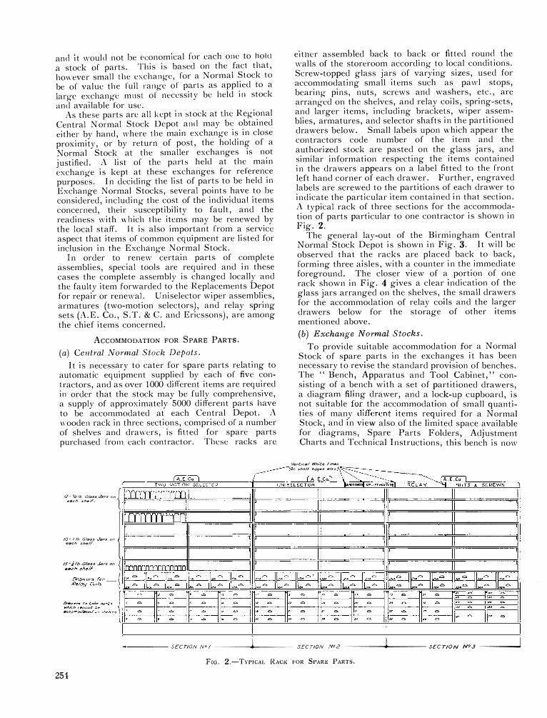
elt11cr assembled back to back or fitted round the walls of the storeroom according to local conditions. Screw-topped glass jars of varying sizes, used for accommodating small items such as pawl stops, bearing pins, nuts, screws and washers, etc., arc arranged on the shelves, and relay coils, spring-sets, and larger items, including brackets, wiper assemblies, armatures, and selector shafts in the partitioned drawers below. Small labels upon v.:hich appear the contractors code number of the item and the authorized stock are pasted on the glass jars, and similar information respecting the items contained in the drawers appears on a label fitted to the front left hand corner of each drawer. Further, engraved labels are screwed to the partitions of each drawer to indicate the particular item contained in that section. A typical rack of three sections for the accommodation of parts particular to one contractor is shown in Fig. 2.
The general lay-out of the Birmingham Central Normal Stock Depot is shown in Fig. 3. It will be obse�ved that the racks are placed back to back, formmg three aisles, with a counter in the immediate foreground. The closer view of a portion of one rack shown in Fig. 4 gives a clear indication of the glass jars arranged on the shelves, the small drawers for the accommodation of relay coils and the larger drawers below for the storage of other items mentioned above. (b) Exchange Normal Stocks.
To provide suitable accommodation for a Normal Stock of spare parts in the exchanges it has been necessary to revise the standard provision of benches. The '' Bench, Apparatus and Tool Cabinet '' consisting of a bench with a set of partitioned d�awers a diag;am filing drawer, and a lock-up cupboard, i� n
_ot sUitable for. the accommodation of small quanti
ties of many different items required for a Normal Stock; and in vie:" also of the limited space available for diagrams, Spare Parts Folders, Adjustment Charts and Technical Instructions, this bench is now
Vertical White Lines (on she/F edge.s 17/so J=- =-----(A.£<:� � . \�------------ � � -TWU�-�-�CTOR��-+�---,-;;:;��IA�EE�.CC�oo .. LI�\\="'� �� ----------------::::::;;:,-.,,_-==� �::o.JIA�EE�.CC�oo.l_l���
TWO MOTION SELECTOR UNISELECTOR ... tNOl!sMJOi11MPULSfMACH1NEI RELAY ........... NUTS � SCREWS
12- k? 10 Glass Jars on { II rlll lr II II II II I II II e�ch she/T
/O- llh (j/�ss J�rs on
l li=1=1=r1=rll=l=l =i l=llll = ll ll=#=======dlir======#======;j i �=====��=====J �ach she!F
/S-Jlb Glass Jars on { each shelr. 11 n 11 n n 11
.,__ ____ SECTION N° /-----\f.----- SECTION Ng 2---------1\f.---- SECTION N9.3------"i
FIG. 2.-TYPICAL RACK FOR 5PAR!l PARTS.
254

F1<;. 3.-BIRMIXGllAM CEXTR.\L :\oRM.\L ·n>ci; Ou•oT.
lo connexion with the Normal Stock, a bottle-rack constructed of metal and arranged in tiers for accommodating 95 bottles of various sizes, and containing a 5-partition locker at the base, has been designed to fit inside the Steel Press. Three racks per exchange arc provided and when fitted into the press occupy exactly one half of the available space and provide accommodation for 300 different items. As the bottleracks arc arranged to rest on the shelves provided with the press, they may be accommodated either above each other in one section of the press, or in the top portion of each section according to local requirements. The partitioned lockers on each rack arc provided for storing armatures, coils and other spare parts which are not suitable for inclusion in glass hottles. The general adoption of screw-topped gla s jars for the storage of spare parts at the Central ormal Stock Depots and at Automatic Exchanges is by reason of the fact that the parts are �uperscdcd by the provision of the " \\"orkman's
Open Type Bench," a 4' Steel Press, and one or m�1
:e separate fo�I cap diagram filing cabinets.
I he separate diagram filing cabinet is of considerable advantage when, as in the case of large exchange-, the apparatus is situated on more than one lloor of the building.
FIG. 4.-PORTION OF RACK.
free from dust, are directly visible and easily accesible. Glass jars of this type arc also low in cost
and are obtainable in numerous sizes suitable for the purpose .
. \ view of the bottle-rack is gi,·en in Fig . 5 and a set of bottle-racks and bottles housed in the Steel Press and sufficient for an Exchange Normal Stock are indicated in Fig. 6. The remai ning ponion of the Steel Press is for the storage of Tally Cards,
pare Parts Folders and Technical Instructions; al o for special items of exchange plant such as Testers and Vacuum Cleaner Tools.
AccouNTINC PROCEDURE.
I n dealing with stores it is essential that accounting records should be clearly and accurately kept. It is, however, desirable as far as possible to reduce the amount of record work, and in order that the scheme may work as easily and efficiently as possible, the procedure in dealing with spare parts at the Central Normal Stock Depots and in the exchanges has been made a simple as possible. A general maintenance order Lo cover all supplies and the time of workmen employed at the Depots has been introduced, and this has had the effect of reducing to a minimum the amount of work involved in the allocation of costs.
/\teach Central ormal Stock Depot a Tally Card record is maintained of each item held in stock. /\ description of the part, the contractors code number :rnd authorized stock, and a reference to the location, i.e., number of rack, bottle or drawer, appears on the heading of each tally card. It is therefore possible to note the quantity of any item held in stock by turning up the tally card and to locate the particular item when this is necessary.
As an additional means of locating quickly a position on the racks, the latter are divided into several sections for the accommodation of parts
255

FIG. 5.-UOTTLE KACIC
relative to difTerenl types of equipment such a Lwomotion selector parts, uniselector parts, relays, screws, etc., and the c details also appear at the top of the tally cards referring. These details will be ob crvcd by reference to Figs. 2, 3 and 4.
flt;. 6.-STE�L i'llESS llOUSING BOTTLE RACKS.
256
For purposes of accounting, the spare parts are divided into four classes as follows :-
Class" JI." \·ery small items of little value and too trifling to count.
Class " B." I terns not included under Class " A " and having a value up to 3d. each.
Class " (;." Items not included in Classes'' A ''and'' B ''and of a value of 3d. each.
Class " U." Items not included under Classes ' ' A,'' ' ' B '' and " C " and having considerable value and infrequently used.
The items in lass " D " are held at the Central Depots only and are obtained by the exchanges on a " :\laintcnance Exchange " basis (by means of the usual requisition for this purpose).
Periodic contract!> at bulk prices are placed with the contractors by the Stores Department and subject to the ordering of parts at certain minimum
quantities an economical purchase price is thus obtained. Supplies arc normally obtained quarterly, and in order to save time in the preparation of requisitions, schedules of the parts particular to each contract are printed, and when a demand is made from one of the Central Normal Stock Depots it is only necessary to fill in the quantities required. Emergency demands are made on ordinary requisition forms and may be submitted at any time. The parts are received direct from the Contractors Works and Delivery lotes are issued by the Stores Department.
The Contractor's Code numbers and descriptions are used in every case, these having been used in the preparation of the pare Parts Folders supplied by the contractors for issue to the exchanges.
At the Central Normal Stock Depots a tally card record is kept of all receipts and issues in respect of item in Classes " B," " C " and " D." 'o record of issues is made as regards items in Class " A," but figures of bulk receipts are entered, and a quarterly balance is recorded by weighing or other means.
Requisitions for the replenishment of Exchange ormal Stocks are received from the various ex
changes at the encl of each quarter and refer to items in Classes " A," " B " and " C." Other items in Class "D," for which " l\laintenance Exchange " requisitions are submitted are received at any time and in the majority of cases are dealt with by return of post.
The issue of Local Orders by the various exchanges is dispensed with under this scheme, but occasions sometimes arise when a particular part required is not kept in stock and the issue of a " Local Order " is necessary. To hold a stock of every item used on automatic equipment would not be economical, and to cover cases where an item demanded is not in

stock, and at the same time keep the proce?ure as simple as possible, any such items are obtamed on Local Order by the Central Normal Stock Depot in the particular Regional Area concerned. Any items frequently obtained in this way are subsequently added to the list of items held in stock.
A record is maintained at each Depot of all scrap, which is sorted out under three headings, i.e.,
" Scrap Mixed �[etal," " Scrap Springs with contacts " and " crap Springs with platinum contacts, '' and is despatched to the Stores Department at the end of each quarter.
At the exchanges a tally card record is maintained of all items in Classes " B " and " C." Individual entries arc made for all receipts and issues in respect of items in Class " C," but for " B " items it is only necessary to record the balance in hand and the quantity obtained at the end of each quarter. No record is kept of parts in Class " A." As in the case of the Central Depots, tally cards are kept for recording quantities of crap, but from the exchanges the material is despatched to the Central Depot instead of to the Stores Department direct.
For purposes of identification a system of coding the racks and bottles containing the parts has been adopted and is briefly as follows :-The three racks arc allotted " key letters," X, Y and Z respectively and these letters are signwritten on the locker door of each rack immediately above the figures 98 which refer to the centre partition of the locker. A circular gummed label approximately t • in diameter is affixed to each bottle, the latter then being numbered consecutively on each rack from I to 95 to correspond with the numbers engraved on the rack. In addition to the number, the key letter of the rack referring is printed on the label, tlius bottle No. 15 on rack" Z " would bear a label marked " Z 15." For reasons of accounting, and as a further means of easy identification, the labels are marked in various colour inks, black being used for bottles containing " A " items, green for " B " items, and red for " C " items. Labels marked in similar fashion are aflixcd to the inside of the locker doors opposite the appropriate partitions.
The details mentioned above appear at the top of the relative tally cards which are filled in groups in accordance with the key letters, and in numerical sequence for each group. Information regarding the description of the part, the contractor's code number and class also appear at the head of each tally card in the same manner as employed at the Central Depots. A box suitable for accommodating 300 tally cards is provided locally and kept in the steel press in close proximity to the Torma) Stock.
\'OL. XXVJI. R
EXCHANGES UNDER 900 LINES, lJ.A.Xs, AND P.A.B.Xs.
Exchanges under this heading do not hold a Normal Stock of parts, but supplies for maintenance purposes may be obtaine? from the Nor.ma) Stock of a neighbouring automatic exchange with the �ame contractor's equipment, or direct from the Regional Central ormal Stock Depot whichever is the most convenient. In many cases the former is the most convenient and speedier method, and is to
_be pr�
ferred whenever possible. Exchanges 111 this category may also make full use of the Repla�em�n�s Depot for performing replacement work which 1t is not possible to do on site. In the case of the U .A.Xs spare common equipment relay-sets are held at the local Section Stock and parts urgently needed are taken from these relay-sets and replaced as soon as received from Central ormal Stock. Only parts required for immediate use may be requisitioned by these exchanges, thus the holding of small unauthorized stocks of parts is avoided.
REPLACEMENTS DEPOTS.
As the name implies, these Depots are for replacement work and a Depot of this character has been established to work in conjunction with each Centr'.11 Normal tock Depot. In order to carry out certam replacements, special tools. _
are required an? for economical reasons the prov1s1on of such tools 111 the exchanges is not justified. It will be readily understood that replacement work in connexion with the maintenance of automatic equipment embraces a very large field of duties, but the major portion of the work undertaken at the e Depots may be summed up under the following three headings :-
(a) Replacement and re-assembling of relay spring-sets.-A.E. Co., S.T. & C. and Ericssons automatic type relays.
FIG. 7.-LONDON REPLACEMENT DEPOT.
257

(b)
8.-ADJUSTING RELAYS, LONDON DEPLACEMENT DEPOT.
Re-assembling of relay spring-sets (i.e., changing of individual springs).-G.E. Co. and Siemens automatic type relays.
(c) Repairs involving tl.e changing of individual parts of wiper assemblies, armatures, cam springs, etc.-Uniselectors and Two-Motion Switches of all types.
Two views of work in progress at the London Depot are given in Figs. 7 and 8.
The provision of a comprehensive file of adjustment data and spare parts information is essential to the functioning of a Replacements Depot, and files in respect of all types of equipment installed in each Regional Area are maintained in the respective depots. Additional copies of Spare Parts Folders and Adjustment Charts are supplied by the contractors on the installation of each exchange and these are forwarded to the Replacement Depot in the particular area concerned.
All apparatus before leaving the Replacements Depot is fully tested and adjusted in accordance with the details supplied and normally any further adjustment in the exchanges is not required.
Faulty items forwarded for repair by the exchanges are accompanied by a faulty apparatus label TE.286 and a triplicate delivery note. The repaired item on return from the Replacements Depot is also accompanied by a triplicate delivery note and the " C "
copy, after having been signed by the officer actually receiving the stores, is returned to the Depot for filing. A record of the amount of replacement work carried out in each Engineer's Section is maintained at the Replacements Depot. In addition to maintenance work the Replacements Depots may be utilized for modification work and the assembling of relays for " Small Works." The carrying out of work of this nature is not only done more effectively, but has also economical advantages and tends to increase the efficiency of the Depots.
A Transmitter Amplifier for Subscribers' Use
There are a number of telephone subscribers who, for physical reasons, are unable to speak at normal loudness. l n order, therefore, to enable them to conduct a telephone conversation in comfort, it is necessary to provide a telephone instrument in which the sending efficiency is made unusually high without reducing the receiving efficiency. A transmitter amplifier using dry batteries has been designed in the Research Section and has been given a practical trial by an interested subscriber with the result that an application has been made for a mains-operated instrument to form a permanent installation.
258
A mains-operated instrument is being constructed to work from either A.C. or D.C. mains. The instrument consists of a single-stage amplifier giving a maximum gain of about 20 db. The transmitter amplifier and the receiver are associated with a Coil Induction No. 20 which reduces the sidetone to a minimum and prevents the circuit from howling. The transmitter feeding current is supplied from the mains in the A.C. case, but in the D.C. case safety requirements make it necessary to use a separate local battery for feeding the transmitter.
No separate Bell Set will be required since the whole of the apparatus will be contained in one case.

Electrical
Post
and Other Services at the
Station Office Research
Introduction.
PROBABLY nowhere in the Post Office En
gineering Department is such a wide field of electrical communication engineering covered
as at the Research Station (Fig. 1) and the methods adopted in providing the necessary supplies to the
,. ...... ""'
,--·-·----·� I E§J ···-··· - I L __ _'.'::_ ____ __J
R. S. PHILLIPS, A.M.l.E.E.
ELECTRICAL POWER PLANT. Electrical power is received from the Willesden
Borough Council sub-station erected at the North East corner of the site. The supply is three-phase, four-wire, 50 cycles, with a voltage of 240 between each phase and the neutral, and 415 between each of
f
the phases. It is brought from the sub-station to the main switch room,
@;) �, �-.. -�,
Fig. 2, situated between the generator room and battery room on the ground floor of the Central Building, by two armoured cables : each cable is 4-core, three cores 0.2 sq. inch and one core 0.1 sq. inch. The cables are terminated behind the main switchboard on oil-immersed circuit - breakers, which are cabled to the bus-bars via the Company's meters and the Station's recording kilowatt meters. Normally, both breakers are closed so that the load is shared between the two main cables, but, in the event of a fault occurring on one cable, the other
-""'"'"'_,.,_,.
[l D
B 1--,.·� �:[,�. I I ";:�"::,, I
[:.::. J
i'
........ ..,"""" ...,._,,""' .. �....._ ..... ., '' '"'',. ""--'"' ""' ... '"""' •.. .,,,.,. . ....., J•o _,__,,,...,,,,,
-.. _ .. ,_,,.,
:�:i ":!\J··:.:;,::.·······:
1 i L. ......... --------·- .J �
FIG. !.-RESEARCH STATION LAY-OUT.
with its associated switch and meters is of sufficient size to deal with nearly the full station load. As the power is paid for on the maximum demand
various laboratories and workshops must often have been a matter of more than passing interest to many members of the Department. During the past few years and especially since the erection of the new buildings and the advent of the Training School, the Station has been visited by large numbers of all grades of the engineering staff. Visitors and students have from time to time asked questions such as, " What method is adopted to distribute all the telegraph, telephone, repeater and special voltages to the laboratories,'' '' How does the staff locator work," " What would the staff do in the event of a fire," and so on. It is therefore thought that an article on the various electrical and other services would be of interest to members of the engineering staff.
system (a fixed charge per kilowatt of maximum demand, plus a charge for each unit consumed), each of the two Company's meters registers the maximum demand in kilowatts as well as the consumption in B.O.T. units on its particular cable. The two recording wattmeters, each having a range of 200 kilowatts, serve as a check on the Company's meters and furnish useful information to the power engineer as to when the maximum loads are likely to occur and so enable him to keep the maximum demand figure to the lowest possible, consistent with satisfactory service. In addition to these meters, a few of the more important sub-circuits are provided with energy meters, one of which is cabled in a semipermanent manner only, so that it is possible at short notice to use it for metering any of the sub-circuits
259

each is fitted with an air-break circuitbreaker having overload and reverse current releases, ammeter, voltmeter, double-pole knife switch, field regulator and fuses. l\larble was used not because it was thought the best possible material, but due to the fact that nearly half the panels were constructed of this material about ten years ago and were in use in the wooden huts before the erection of the permanent buildings. To preserve uniformity, the newer panels were similarly constructed, despite the short-comings of marble due to lack of homogeneity and susceptibility to oil and grease. All holes in the panels are, of course, efficiently insulated with micanite bushes and washers.
Main Battery Room. (Fig. 5).
FrG. 2.-MAIN A.C. SWITCllBOARO--CENTRAL BUILDING.
The majority of the D.C. supplies to the laboratories are obtained from stationary secondary cells housed in the main battery room adjacent to the
to which meters are not normally fitted. An idea of the size of the undertaking will be obtained from the fact that during the winter quarter of 1933 the
maximum station load was 222 kilowatts and the total units consumed 91,500, these of course being the sum of the readings on the two meters.
From the main switchboard, the A.C. supplies are distributed to various parts of the station from triplepole ironclad combined switches and fuses of capacities ranging from 60 amps to 200 amps. Two of the smaller switches serve two dis-tribution boards which supply current via motor starters to the motor generator sets in the adjacent generator room, Fig. 3. Each of the motor generator sets rests on pads of cork or rubber and none is bolted to the floor, so that there is little risk of vibration from the machines being transmitted through the building. Details of the generator sets and the uses to which they are normally put are shown in Table I.
The cabling from the main switchroom is such that it is possible to connect any of the sets to any laboratory, which is sometimes necessary when non-standard voltages are required for special tests.
Generator Control Panels. (Fig. 4).
The generator control panels for Sets 1 to 12 inclusive are erected in the main switchroom, whilst those for the remaining sets are in the laboratory which the particular set normally serves. The panels are of marble and
260
witchroom on the opposite side to the generator room. With the exception of
the 60-volt battery which is continually floated by Set 8, all the main batteries are in duplicate, one on each side of a central gangway, so that whilst one is being charged the other is discharging. The various batteries are shown in Table II.
A pair of cables terminated on a switch is run to each half of the battery room from Set 3, so that with the aid of flexible leads the set can be used to boost any cell in any of the batteries.
FIG. 3.-GENERATOR ROOM-CENTRAL BUILDING.

TABLE I.
Set No. Motor. Generator. Normal Use. -· -- ------------ -- ----1----------·- ---- - --
I 3-phase and 6-pole induction
___ 2
___ i_2_3_I_-I_
. P_
. __ ___ _______ _
3 I
4 and
- 1 -
5 I
3-phase 4-pole induction 2 H.P. -·---------- 1
3-phase 4-pole induction 6.8 H.P.
D.C. shunt wound-10.3/15 kilowatts-220/320 volts.
D.C. shunt wound! kilowatt-4/ I 0 volts.
D.C. shunt wound-4 kilow:itts-40/100 volts.
For charging the main 240-volt batteries.
Booster machine for boosting any cell in any of the main batteries.
For charging either or both halves of the 22v +ve 22v -ve and 40v +ve 40v -ve batteries.
------, ------- ----- · -- ------------ - --------------------------
6 3-phase 4-pole induction 3.5 H.P. I --- -----
1: -------------
7 1 I
8
3-phase 4-pole induction
13.5 H.P.
3-phase 4-pole induction 3.5 H.P.
D.C. shunt wound-2 kilowatts-2/20 rnlts.
D.C. separately excited field-
7.5 kilowatts-100/240 volts.
D.C. shunt wound-1.8 kilowatts-60/ 100 volts.
For supplying heavy current, low voltage, to any laboratory for current measurements.
Distribution of 110 volts, D.C., to laboratories for oscillograph arcs and small motors.
For charging 60-volt battery which supplies current to durability laboratory.
------ - - ----------- -------- - ----· · ------·------------------
9
10
II
12
3-phase 4-pole induction 2i H.P.
3-phase 4-r.-ole induction 6\ H.P.
D.C. compound wound-
1 kilowatt-12/14.5 volts.
D.C. compound wound-'
3.5 kilowatts-100 volts.
- --------
------ -
3-phase 4-pole induction 2� H.P.
D.C. shunt wound-1.2 kilowatts-20/40 volts.
--------- 1------ - ---
3-phase 4-pole induction
12 H.P.
D.C. shunt wound-9 kilowatts-50/75 volts.
For supplying current to the secondary cell testing bboratory. The motor starter is fitted with a trip which open circuits the no-volt coil and stops the machine when the cells have been on charge for the required period. The cells are isolated by the operation of the reverse current trip on the circuit breaker.
Supplies power to photographic laboratory for film projection in the lecture theatre.
For charging 24-volt batteries in main battery room.
For charging the main 50-volt batteries.
------·------ - - --
13 3-phase 4-pole induction l H.P.
D.C. shunt woundt kilowatt-300 / 500 volts.
------ ----- ------ ·� ---- --- ---
14
15
110-volt D.C. shunt �H.P.
A.C. 30-pole-2000/3600 r.p.m.directly coupled-maximum frequency
900 c.p.s. output 60 volts-! amp
---- ------- 1 -------·-- ·----
, 240-volt D.C. shunt I� H.P.
A. C. 30-pole-830 /2000 r.p.m.belt-driven with various
pulley ratiosmaximum frequency
8000 c.p.s. output 100 volts-3 amps.
Supplies current to laboratories for high powered amplifiers.
----------------- ------ ----· - --
For general A.C. testing in the electrical testing laboratories, The control panel including field regulator, meters, and motor starter, is fitted in the laboratory.
-- ------- - - ----------------
For general A.C. testing in the Signalling Apparatus and Circuits laboratories in which the control panel is fitted.
------- ------------- 1---------------------------
16
17
240-volt D.C. shunt 0.7 H.P.
3-phase induction 0.7 H.P.
Manual telephone exchange tone generator (Busy, ringing, dial,
etc.).
Automatic telephone exchange tone generator.
Transmits manual exchange tones to the Signalling Apparatus and Circuits laboratory.
---------------
Transmits automatic exchange tones to the Signalling Apparatus and Circuits laboratory.
261

....
Line Transmission Battery Room. (Fig. 6).
In carrying out work on repeaters, it is essential to avoid voltage variations due to battery leads resistance. Consequently , it was decided to install two 24-volt batteries (500 Ah} and two 150-volt batteries (16 Ah} with back e.m.f. cells to give 130 volts, in a battery room adjacent to the Line Transmission �Jain Laboratory. The 24-volt batteries are charged by a copper oxide rectifier and the 150-volt batteries from the main 240-volt batteries.
FIG. 4.-GENERATOR CONTROL PANELS, SllOWING MOTOR STARTERS ON THE
RIGllT AND MAIN A.C. SWITCllBOARD IN Tllll BACKGROUND.
It is now generally recognized that insulating oil has a deleterious elTect on secondary cell plates, but to discover whether any particular oil is better than another, several different grades are being used on these batteries which will periodically receive test discharges to ascertain how their capacities have been affected.
Battery voltage.
24
44
50
60
-
80
150
240
262
TABLE II.
Capacity Ah.
-
250
250
1000
250
120
24
250
Remarks.
upplies current to the Repeater School.
Centre earthed for work.
telegraph General distribution to
laboratories.
Being the standard automatic exchange voltage, the battery
is distributed to all laboratories.
Serves Durability laboratory only. As constancy of voltage is a necessity the battery is continuously Aoated by Set 8.
These batteries are formed by connecting nine cells in series at each end of 44-volt batteries. Distributed to most labora-tories, the centre earth being again for telegraph working.
Back e.m.f. cells are installed to provide 130 volts. General distribution to laboratories mainly for supplying the plate voltage for valves used in connexion with work on repeaters.
Distribution to laboratories for general testing.
Battery Control Panels. (Fig. 7).
With the exception of the 24-volt and 150-volt Line Transmission batteries the main battery control panels are erected in the main switchroom and, as in the case of the generator panels, are constructed of marble. Besides the necessary switchgear for putting either battery o. 1 or No. 2 on charge or discharge, each panel is fitted with a pair of fuses, a voltmeter, and an ampere-hour meter.
Portable Cells.
In addition to the above stationary batteries, a number of portable cells are held for issue from the battery room to any of the laboratories. These cells vary in capacity from 18 Ah to 110 Ah with a number of portable batteries (22 and 50 volts) of capacities 1.1 Ah and 3 Ah. They are used for supplying valve filament and plate currents and for tests which cannot be satisfactorily carried out by using a common battery. Copper-oxide and tungar rectifiers housed in a partitioned corner of the battery room where the cells are normally kept supply the charging current. A pair of leads is also provided from the battery distribution panel so that the battery attendant can charge portable cells from any of the main batteries.
CABLE DrsTRIBUTION.
A.C. and D.C. voltage are distributed to various parts of the station from the main switchroom, the former from combined ironclad switches and fuses on the A.C. switchboard and the latter from selfaligning fuses mounted on marble panels erected near the battery control panels. The cables are distributed from the switchroom in four directions. Those buildings on the North side of the Central Building are supplied via an underground tunnel
which connects it with the Training School and work-

Fie. S.-M111N BATTERY RooM-CENTRAL Bu11 DING.
shops. Cables to the buildings on the \Vest sideRadio laboratories, Chemical laboratory, Durability laboratory, Garage and Stores block-are run in twelve tee! conduits which connect the Central Building \\"ith the \Vest side covered way. The General Research Building on the South side receives its supplies from a switchroom built in the basement and fed from the main switchroom via the basement of the Central Building. The buildings on the East side-Training School lecture rooms, Refreshment Club and Cable Laboratory (the latter two not yet
Basement Switchroom. (Fig. 9).
In the basement switchroom of the General Research Building, the A.C. lighting and power cables from the Central Building-L.C. armoured 4-core-are terminated on two triple-pole ironclad switches and fuses fitted with overload releases and cabled to the A.C. bus-bars. Three ironclad doublepole switches and fuses (one for each phase) control the cables feeding singlephase power, whilst three similar switches serve the 240-volt lighting cables. In the case of both lighting and power, care has, of course, been taken to balance the loads as far as possible between each of the three phases. Three-phase power is fed from a triple-pole distribution case and combined switch and fuses cabled to the bus-bars. The D.C. mains from the Central Building are terminated on selfaligning fuses mounted on black-enamelled slate panels from which the distribution cables run to a D.C. plug
panel in each main laboratory. A " special voltage " panel is also erected in the basement switchroom about which more will be said later.
Labo-ratory D.C. Plug Panels. (Fig. 10).
Each plug panel serves the bench panels in its main laboratory and group of adjacent smaller laboratories. The live cables are brought to the sockets in the top half of the plug panel whilst the sockets in the bottom half are cabled to the bench panels from which power for the various tests 1s
built)-will be fed through a sixteenway self-aligning duct line which will connect the East covered way with the Central Building. The buildings on the East and West sides have entries into the East and West covered ways respectively. The four floors of the General Research Building are connected by four vertical chases, each 3' o· by 2' o·' which run, two from the basement on the east side and two on the west side with an entry to each chase in the corrider on each floor, Fig. 8. The laboratories on each floor are served by corridor chases (5' 6* wide by 3' o· high) which run almost the full length of the building, one under each corridor. Access to these chases is by trap doors in the laboratories and offices. The main cables, A.C. or D.C., for a particular group of laboratories in this building are thus run from the basement switchroom to the basement, up either East or West vertical chases to the required floor, thence along the corridor chase to the particular laboratory.
F1c. 6.-LINI! TRANSMISSION BATTERY ROOM, SllOWINC AN ENTRY TO ONI!
OF Tiii! I-IORIZONTAL CoRRIDOR CllASES.
263

,_ J_
apparatus. Space is provided for the fitting of an additional s\\·itch if required in the future, and a few of the panels have already been so equipped. The bench panel A.C. switches arc cabled direct from ironclad distribution boards fed from the .\.C. power switches in the basement switchroom. Distribution from the bottom half of the plug panel to the bench panels is carried out in chases under the bench tops which arc removable. Floor
C chases with removable \\·oodcn covers arc provided where necessary to feed the benches.
j 1111ctions.
A junction panel is installed adjacent to each plug panel (Fig. I I) with the object of enabling any bench panel to
FIG. 7.-MAIN BATTERY CONTROL PANELS-CENTRAL BUILDING.
C be readily connected to any other not only in its own group of laboratories but to any laboratory on the station. Each bench panel is served by four cables-one-pair, 20-lb., I.R.V. core, L.C. twinned-from its main junction
taken. Any voltage from the plug panel can be obtained on any of its associated bench panels by connecting the appropriate pair of sockets in the top half to a pair in the bottom half by two flexible cords with a plug at each end; if no plugs are inserted in the plug panel, the bench panels are " dead." The plug and bench panels are made of polished '' Sindanyo,'' which has the advantage over slate that it is homogeneous and thus the holes require no bushing and over ebonite that it keeps its colour over a very long period.
In addition to its normal voltages, each plug panel is served by a spare pair of cables from a " special voltage " plug panel in the basement switchroom from which four pairs of cables run to the main switchroom in the Central Building. By means of flexible cords and plugs, this enables any special voltage from any of the machines or batteries to be supplied to any of the laboratory plug panels.
Laboratory Bench Panels. (Fig. I I).
A standard bench panel is fitted with three 15 amp. D.C. combined switches and fuses and one 15 amp. A.C. switch plug of the interlocking type, the latter being mounted horizontally. Hence it is possible to obtain three of the plug panel voltages simultaneously on each bench panel in addition to an A.C. supply. Two pairs of terminals are mounted on the panel adjacent to, and cabled from, each of the three D.C. switches to facilitate connexions to
264
panel, the cables being terminated on four pairs of terminals at the bench panels and on eight jacks at the junction panels; in one or two cases terminals are used instead of jacks. There is available space on bench and junction panels for future extension to eight pairs. To afford the facility of readily connecting together any of the laboratories on the station, each junction panel is connected by six cables, each one-pair, 40-lb., I.R.V. core, L.C. twinned, to a central junction panel on the first floor of the General Research Building from which similar
FIG. 8.-ENTRIES TO VERTICAL CABLE CrrASES.
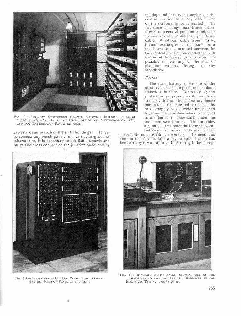
making similar noss connexions on the central junction panel any laboratories on the station may be connl'('led. The lelephonl' cxchang.e main frame i-, connected to a central junction pant!, near the one already mt•1Hioncd, by a JO-pair cabk. .\ 24-pair cable from T . . X. (Trunk t•xchangt·) is terminated on a
trunk ll''-l tablet mountt·cl bt•t\\ l'l'n the t\\O central junction panels ..,o that \\ ith the aid of fkxible plugs and cords it is possible to join any of the side or phantom circuit.., through to any laboratory.
F:11rt/1s.
FIG. 9.-BASEMEST SWITCllROOM-GESER.\L RESE.\RCll Bu11 DIM,, SllOWll\G
The main battl'n· carths arc of the u-,ual type, consi..,tfng of copper platl•s t•mbedckd in cokl'. for screening and protection purposes, earth terminals arc prm idcd on the laboratory bench panels and are connected to the sheaths of the supply cables which are bonded together and arc themsel\'CS connected to another earth plate sunk under the basement switchroom. This provides
" PECIAL Vo1.T.\GE " P,\NEL IN ENTRE, p,,11T OF A. . Sw1TCllROOM ON LEFT,
Al'D D.C. DtSTRIOUTION PANELS ON RIGllT.
cables are run to each of the small buildings. Hence, to connect any bench panels in a particular group of laboratories, it is necessary to use flexible cords and plugs and cross connect on the junction panel and by
FtG. 10.-LABORATORV D.C. PLUG PANEL WITll TERMINAL J'ATTERN jUNCTION PANEi. ON TllE LEFT.
a suitable earth potential for most work, but ea es not infrequently arise where
a specially quiet earth is necessary. To meet this need in the Physics laboratory, a special earth has been arranged with a direct fet•d through the labora-
FIG. 11.-STANDARD BENCll PANF.l., 5110\VING ONE OF TllE TllBRMOST\TS COSTROLLING ELECTRIC RADIATORS IN TllB
ELECTRICAL TESTING LAllOR.\TOIWlS.
265

tory wall. When the main roadway system (of reinforced concrete) was laid down, the opportunity was taken to bond together several of the iron reinforcement grids and to connect them by cable to the plug panel in the Line Transmission laboratory, so that this earth may be used by any laboratory. Finally, a special earth has been provided for the impulse generator (which gives instantaneous heavy discharges at 250,000 volts) because the ordinary earth leads are too long to give efficient protection with such steep-fronted discharges.
LIGHTING.
employed in the main entrance hall and stairway of the General Research Block, in the Lecture Theatre, and the Library. Ten pendants, each consisting of a cluster of four 100-watt and one 200-watt lamps, provide the lecture theatre with excellent illumination, whilst in the library a rather novel method of concealed lighting has been installed. Around a cornice near the ceiling 25-watt lamps at 1 ft. spacing are fitted and rendered invisible from the floor by thin strips of frosted glass. The result is a pleasing and efficient diffused illumination over all the tables. For the sake of economy and to suit individual requirements a table lamp is fitted on each of the five tables. The lighting cables to the sub-distribution boards
are either plain lead-covered I. R. V. core or lead-covered and armoured, whilst from these boards to STAFF LOCATOR. the fittings the standard method of l.R.V. cables in During the past few years the number and extent conduit is employed. Corridors, lavatories, etc., of the buildings have gradually increased and it was are fitted with the usual 25-watt pendants : totally becoming very difficult to locate senior members of enclosed fittings with either 100-watt or 150-watt the staff when urgently needed. Some form of lamps serve the laboratories and offices. All lamps staff locator became a necessity and as none of in the workshops are fitted with enamelled iron the types on the market was considered quite shades to lessen the risk of breakage : since the suitable, it was decided to design a locator and shades are metallic, they are insulated from the the one installed is composed entirely of standard holders to minimize the risk of shock. In the Post Office apparatus (Figs. 12 and 13). Each laboratories, the general lignting is supplemented senior officer (Staff Engineer, Assistant Staff where necessary-for microscope work, relay adjust- Engineers, and Executive Engineers) is allocated a ments, etc.-by portable flexible arm fittings capable number of one or two digits and if he cannot be of being plugged into the sockets of the A.C. located by the ordinary telephone system, the switches on the bench panels. Emergency lighting operator throws a key and dials the appropriate code is provided in the main and basement switchrooms number. This causes the lamps behind the corre-from the 240-volt batteries in the event of a failure sponding digits on the locator boards to flash inter-of the Company's supply. Special lighting is mittently-0.75 sec. on, 0.75 sec. off. The faces of
266
A '
J"' �''"
75 sec on 75 oH
�·/ [°fro n�.•.'
To T41U!I.�
,1:1:0 .. ?..l
4 s • ,, " " ., ., .. " " "
DRY CCLL�: - -I� DOOR llUTTON COPPER Oilt0£ RECTIFIER
ULE llCLL SCT p " �' 000RK£CPERS <OO<C
- - - -? t;tt- �,,�,: . ., "'"'"" j lamp No3
ll�I· ,! ---- ---- - -,---- TtAI
OJ "" o• 60 " " " ..
" 6l
"'T2A2
To � '1\ I'.��� �' bs .. I
' r· "!:t.sso•:. To Cont.;i.:t,
�� T6Al-4
UIA4 _/� To Contacts UJAt-4, U5Al-4
Fuse Nol servos T2At- 4 101 4 Tt.AI· .. --· NoZ T2AS·• T4Ab·I! T6A5·8
No3 Ta1-4 T.01-4 T6e.1 4
�:: ����-: �:��:: flt��= No6 Tzcs·e T4CS·8 T6c5·8 No7 U1A1-4 U3At·4 UsA1 • No8 UtA5·8 U.!AS-8 U.5.45·8 No9 Utet·4 UJel·4 U.se1·• No10 · U•BS·B U3es-s.Uses-e Noll • U1c1·4. U3c1-4. Usc1·4 Noll U1CS·8 U3C5·8 U5C5·8
RELAYS FITTED ON LAflPS NO 11. NO;J 01" HALF THE STAF/l'
Lamp No I ���,.,.�:t,:SA"Ns SERVICE
g -1''/ •9/ L.,;mp Layout
���:;s
llpul•b
, l��·��tor ILf)+I ./ I JNSTALUD
- -"1 WHEN
, , I 'I}
L�iJ RCQUIJtED
FIG. 12.-STAFF LOCATOR CIRCUIT.

. I CAPT COHEN. 26 Ml:! MUMFORD 2 MB BARRALET. 35 Ml:! HARBOTTLE 3 CAPT. TIMMIS. / 41 Ml:! WEST. . 4 MIJ ALDRIDGE. 43 Ml:! TOLLEY 5 Ml:! GREGORY. 45 Ml:! JOLLEY. 6 Ml:! HANFORD. I 46
. 21 Ml:! BARNES. 61 23 Ml:! BEER. 63 24 MIJ BROWN. . 65 25 Ml:! RADLEY.
FIG. 13.-STAFF LOCATOR.
the lamp boxes are 6" x 4" carrying 3!" numbers illuminated by 30-watt lamps. The size and brightness of the illuminated area are sufficient to attract attention without an audible signal since the use of the latter would interfere with tests in progress in the laboratories. There are twenty locator boards at various points on the station and it is, therefore, very probable that the required officer will see the number flash or that his attention will be drawn to it by someone near him.
An extension to the system provides a useful service for the night watchman when on his rounds after official hours of duty. Half the locators, evenly distributed over the station, are each fitted with a bell which rings when either the button at the main gate is depressed or the telephone bell in the gatekeeper's lodge is rung. In addition to the ringing of the bells, Nos. 1 and 3 are illuminated on these locator boards. Thus 13 is a service for the night watchman only and it is not possible to operate this during official hours because the circuit is wired via
the day-night switch on the telephone switchboard. The bells give audible warning and by their ring (intermittent or continuous) the watchman is informed whether he is required on the telephone or by a visitor at the main gate.
FIRE ALARM SYSTEM.
The buildings at the Research Station house a large amount of valuable apparatus, so that apart from danger to life, precaution must be ta)<en to ensure that in the event of a fire outbreak certain members of the staff are efficiently organized to be able to combat the danger. one of the standard alarm schemes in use in the various Post Office Buildings was considered suitable because of the disposition of the various buildings. In the system installed, if the water and sand buckets and cxtincteurs prove insufficient, the operation of one of twenty buttons sounds audible alarms in the two workshops and the General Research Building where the fire fighting squads are normally employed. Further, the seat of the fire is indicated by the lighting of a lamp on each of three indicator boards (Fig. 14) fitted in these buildings. There are twelve hydrants around the station fed by mains water under pressure from a pump in the doorkeeper's lodge. The pump motor is automatically started by a pressure-controlled switch which operates with a fall of pressure due to the opening of any of the hydrants. A " clear out " button fitted close to the Staff and Assistant Staff Engineers' offices operates two t H.P. D.C. syrens, one on the roof of the Chemical Block and one which will ultimately be on the Refreshment Club, but is temporarily installed on the roof of the Training School to serve as a summons to evacuate the station in the event of the fire assuming serious proportions. A separate button mounted on a pillar close to the main entrance of the General Research Building is joined to the Willesden Council Fire Alarm circuit so that, if necessary, the local fire brigade can be summoned.
HEATING.
The buildings are heated by a standard hot water radiator system fed from boilers in the basement of the Central Block. In the electrical testing laboratories where the standard instruments and apparatus are kept, this is supplemented by thermostaticallycontrolled electric radiators. These are totally en-
FtG. 14.-FIRK ALARM INDICATOR BOARD.
267

closed in metal tubes of 2 ins. diameter and mounted on the walls in four banks with 3 ins. between each bank, the bottom being 6 ins. above the floor. The thermostats, each controlling one half of the tubes, are of the bi-metallic strip pattern and can be set to within 1° F. between the limits 48° F. to 78° F.
GAS. Apart from its use in the Refreshment Club for
cooking purposes, gas is distributed to the majority of the laboratories and is terminated on two-way gas cocks fitted on the bench tops. None of the vertical or corridor chases is used for gas distribution, which is everywhere kept clear of the electric cables. A main to the workshops supplies gas furnaces, a coilimpregnating oven, and bunsen burners.
COMPRESSED Arn. A compressed air service is distributed from the
workshop where a 3 H.P. 3-phase motor drives a compressor capable of giving a supply up to 60 lb.
per sq. inch. This service 1s fed to the Chemical laboratory where it is used for experimental work, for example, to produce artificial fog in corrosion testing chambers : to a gas forge in the workshop; and for experimental work in the Physics laboratory where, among other things, it is used to test the durability of cellulose surfaces by blowing carborundum powder upon them.
VACUUM.
A vacuum pump in the basement of the Central Building provides a rough vacuum to the Chemical laboratory, Workshops (Coil-Impregnating plant) and the Mechanical Testing laboratory.
STEAM . A small steam boiler is located in the Central Build
ing basement and is piped to the Chemical laboratory for distillation \vork, etc. The steam is also used in the Central Building for the production of distilled water used in the main and portable batteries.
Telegraph and Telephone Plant in the United Kingdom TELEPHONES AND WIRE MILEAGES. THE PROPERTY OF AND MAINTAINED BY
THE POST OFFICE IN EACH ENGINEERING DISTRICT AS AT 30th SEPT., 1934.
Overhead Wire Mileages. Underground Wire Mileages. Number of Telephones owned and ___ 1 Engineering]-__ _ _____
_ m��nt���ed
1 Telegraph. Trunk. Exchange.* Spare. District. [ TE-legraph. Trunk. I Exchange.* I Spare. Post Office. I -�
41��
22
-- ------
56
-
2
- ---
8,022
--
45,96;
- ---��9
- �ondon - 1 35,755
------:6,992
-T��43,6:- 167,152 103,582 2, 190 18, 184 46,583 5,923 S. Eastern I 4,719 60,816 372,026 62,328 118,524 4,005 36,764 74,689 5,766 S. Western 24,221 51,772 I 295,886 99,072
81,826 4,108 41,270 70,682 9,427 Ea,.tern 15,392 68,124 174,477 I 55,897 129,015 5,767 47,952 57,371 11,956 , N. Midland 9,915 172,533 340,751
[
122,260 104, 160 3,654 29,766 65,239 6,802 I S. Midland 10,218 67,461 1 325,983 72, 171.
70,732 3,166 27,193 57,654 - 8,056 S. Wales 6,180 57,339 167,761 41,298 141,220 4,594 25,136 59,873 12,789 N. Wales 9,062 80,851 455,322 113,724 183,882 948 8,742 26,819 7,892 S. Lanes. 8,728 124,303 [ 671,094 I 80,878 118,652 5,085 24,663 40, 133 8,813 N. Eastern 11, 178 94,399 ,I 347,337 56,867
78,192 1 245 21,586 27,805 8,576 N. Western 4,265 47,840 254,729 56,000 60,325 1.368 14,289 22,550 7,416 Northern 3,929 53,326
I 191, 112
I 32,648
30,052 3,209 I 11,233 12,548 986 Ireland N. 266 5,721 71,265 5,468 86,535 4,383 28,252 41,595 7,896 Scotland E. 1,214 1 55,207 180,211 48,478
_ __1_Cl!l'� 1
---3,2
_3
_0
_i;
__ 23_,
_14
_8 __ ,
__ 3_3
_,_757 5,747 Scotland W. 10,586 49,586 ', 278,230
i 45,699
_
2,256,740
__
11, __
4
_
7
_
,5
_
1
_
4 __ -
366,2
_
0
_
0
-i-
6
-
8
_
3
_
,26
--
2
-
-
_
-
,
, ____ l
-
1
-
l
_
,
-
9
-
34 . , __ �_o_�_a�_s_. ---i -
1�5,6� 1,196,270 1 7,..;,,823
- 1 1,059,940
2,229,837 1 51,105 374,380 673,715 98,985 F�8t'::e}:�e:t 1'---:.:-11 1,166,
-
130- 11 7,804,-::- 1-1,05�.299
-
1934.
* Includes low gauge spares (i.e., wires of 20 lb. or less in cables and 40 lb. bronze on overhead routes). 268

Miscellaneous Facilities Manual Telephone
at Automatic Exchanges
and A. HOGBIN
SPECl.\L FAULTS CIRCUITS AT AUTOMATIC EXCllANGES.
A FAULT on the equipment of an automatic exchange may affect the service of a number of subscribers and, if allowed to persist, it
may prevent the completion of many calls. The immediate location of such a fault is of vital importance.
In certain automatic areas, the " ENG " system of reporting faults direct to the engineers is in operation, but in other areas subscribers complain to an auto manual board operator when they are unable to complete a call, and close co-operation between the operating staff and the engineering staff in handling such complaints is essential. A " special faults circuit " is therefore provided from all positions on the auto manual board to a telephone in the auto switchroom. On receiving a complaint an operator dials, on a trunk-offering train of
(a) Exchange with 900 or less lines, no provision to be made.
(b)Exchange with more than SOO but less than 2000 lines, with manual board in remote building.
Final Selr �nk.
S.F. Tele.
�--------:·i ----------u -··
(CJ Exchange with more than 900 lines, with manual board in same building , also Exchange with 2000 or more lines remote (rom manual board.
Manual Pos. Direct circuit (Intl Of' Ext/ J Vo
Final Selr Sank.
S.F. Tele 0---------i·.:
c::>--{]
Fie. l.-BAs1s OF PRO\'l!>ION OF SPi-:cuL FAl"LTS Crncl'ITS.
selectors, the number of the subscriber concerned and requests him to re-dial the number he requires .
If ringing tone is not heard or if a wrong number is obtained, the operator a ks the subscriber to remain on
. the line and calls the responsible engineering
ma111tena11ce officer on the special faults circuit. Having given him the necessary particulars and after hearing that he has picked-up the connexion on a special hand-microtelephone, the operator releases the trunk-offering selectors and the special faults circuit and leaves subsequent investigations to the engineer.
In view of the small amount of traffic concerned, 'he provision of special faults circuits is governed oy the size of an exchange and whether or not the manual board and the auto plant are in the same
building: Where a separate junction is not justified, the special faults telephone is terminated on a final selector number which can be dialled from auto manual boards and dialling-in exchanges.
Des. Strip.
S.F.C. S.F.C. S.F.C. S.F.C. S.F.C. S.F.C. AB NG2.J.4. NG .S NG 6 BE CA
(a) (b} (C) (d)
FIG. 2.-SWITCllBOARD MARKING.
The basis of provision of these circuits can be summarized as shown in Fig. 1. The dotted lines show a telephone connected in parallel with the main special faults telephone and fitted near to the subscribers uni selectors or 1 st line finders in those cases where these occupy more than one floor of the exchange building. \Vhen a telephone connected to a fin.al selector n�mber is provided, as in Fig. I(c), this
_ telephone 1s fitted near the incoming junction
equipment. For the purpose of uniformity the final selector
numbers have 4 digits and the characteristics 2211,
FIG. 3.-SPECIAL FAULTS TBLEPllONE AND ASSOCIATED EQUIPMENT.
269

.211 whenever possible. A proposal to use 1110 in the London area is under consideration.
Special faults circuits are connected to a single jack in the outgoing junction multiple of auto manual positions and on monitors, supervisors, and test desks. Fig. 2 shows the switchboard marking. Fig. 2(a) is the jack for a circuit to exchange " AB," while the remaining portions of the figure are in respect of a non-director area, e.g., Nottingham. The direct circuit to the main exchange equipment embracing levels 2, 3 and 4, are labelled as in (b). There are two sub-exchanges in the area which are served by levels 5 and 6 and which carry the same name as the main exchange, but which only justify final selector numbers being used for the special faults telephones. These numbers are shown on the jack pegs at (c). The two jack pegs at (d) are final selector numbers for two other sub-
when a call is answered until the caller releases the connexion.
(c) Control of cord circuit supervisory signals from the telephone.
Fig. 4 shows the circuit connexions for the manual position circuit. As the sleeve circuit is disconnected, a loop round a shunt-field relay in the cord circuit operates relay L to connect ringing tone at Ll and the telephone buzzer at L2. When the call is answered, contact Dl operates relay CO to disconnect the buzzer and retain itself at C02, and to disconnect the ringing tone at COl, while the reversal at D2 and D3 causes the cord circuit relay to operate and provide supervision. The operation of the final selector number circuit shown in Fig. 5 is very similar, except that relay RR is operated by the ringing return battery in the final selector. When relay D operates, D2 completes the connexion
Auto. Man. lD.F. 2 MlD.F. Pos'ns. L M (Bridge & q_ ... - :��-::: : .. -_ ·:::.o.:.,_------------.----U·---f---------1 To
Special
J/eeve Control) • '� � , r.aults '::.2:::, Su'P'rs 2 Tt:fenhone. ' ::.;;.'.-�=��� n Desk. L--....--l-....--ff---'t--i----- .,... Monitor's q...... , :·- 0�:: � Desk. ::::::::�� :=;,P "ffe�i.
FIG. 4.-MANUAL POSITION CIRCUIT TO SPECIAL FAULTS TELEPHONE.
exchanges in the area (Beeston and Carlton) which have their own exchange names.
A special faults telephone and its associated equipment is shown in Fig. 3. A wall-pattern instrument, with a buzzer in place of the dial, is mounted on a panel above a card receptacle, the top of which forms a writing desk. " Waiting attention " and " cleared " fault-docket holders are fitted immediately below the telephone. On the right side of the panel two frames are fitted, one for instructions to staff regarding procedure and the other for the '' O '' level grading chart of the exchange. This chart assists in the rapid tracing of emergency manual board calls when the caller is too excited to tell the operator the number of the 'phone from which he has spoken.
The chief facilities provided by special faults circuits are summarized as follows :-
(a) Automatic sounding of the buzzer as soon as a plug is inserted in a jack or a final selector number is seized.
and a loop via RR, thus operating the final selector D relay to cause metering or supervision on the caller's equipment.
A circuit combining Figs. 4 and 5 is available, but as it may only be applicable to tandem exchanges it has been excluded from this brief description.
TEST NUMBER EQUIPMENT. To assist traffic and engineering officers in the
routine testing of (a) junctions terminating on automatic equipment and (b) dials on manual positions, without the co-operation of another officer, " test " numbers are allocated on the automatic plant. When these numbers are dialled, callers receive a
(b) 270
Lock-out of the buzzer FIG. 5.-FINAL SELECTOR CIRCUIT TO SPECIAL FAULTS TELEPHONE.

1.0.F. local 200
Final :Jelr ----.o---..:-
vanes according to the trunking arrangements of each exchange, but generally speaking one equipment is provided for From S£Bre l +
Number. p
Busym�j- ..__n__. 7i:J Inter.
· II� lid-4. Ringing.
I
each group of 1,000 lines. Whenever possible a final selector number is used to which every group of incoming junctions has access, but when this is not possible
Key
A ,ooo y
owing to a manual board having access over separate groups of junctions to different
�
·11��1-111·
2 lOMotor · l�
A ,,'----Start
� Circuit..
blocks of numbers in the numbering scheme, it may be necessary to provide additional test number equipments.
Fig. 6 shows the circuit for test number equipment. Relay A is operated by the final selector, after which relay B responds to the interrupted ringing periods. Relay BA follows relay B, but retains during the 0.2
FJG. 6.-TEsT NUMBER EQUIPMENT CmcurT.
tone and flashing signal of characteristic periodicity. To increase the stringency of the test as regards impulsing efficiency the final selector numbers used include the digits ' ' 0 '' and '' 1. ''
The basis of provision of test number equipments
sec. " silent " ringing period. Therefore, taking into account the combined slow releasing periods of B and BA, there is approximately a tone and flash period of 1.8 seconds '' on '' and 1.2 seconds '' off."
The Control of Amplification in Repeater Systems
At the present time, the power supply at repeater stations consists principally of anode and filament batteries. These in some cases are floating. On the repeater racks, the filament voltage is maintained at approximately 21 ± 0.5 volt, an alarm bell operating when these limits are exceeded. The anode voltage is not specially controlled and has a value generally between 125 and 135 volts, whilst the minimum value may be below 120 volts.
In testing equipment, such as oscillators and transmission sets, the speed of operation and time for recalibration of the equipment are becoming increas-
ingly important factors. To ensure stability of the equipment, a simple control for the H.T. voltage has been tried consisting essentially of a resistance and neon tube. It is very effective and will be applied to heterodyne oscillators and direct-reading measuring sets. The increasing efficiency of trunk circuits leads to the necessity for greater precision in maintenance, and to preserve the necessary margin of stability on a long international circuit the possible variations which may occur in a few repeaters and cable sections constituting one link in the circuit must be kept at a small value.
271

A New Mail Bag Cleaner
I T is well known that it is the Department's
practice to clean the letter and parcel mail bags at the larger Post OOices by means of special
machines. Until recently, a large slow-running drum type of machine was used for the purpose, which was costly in maintenance and required a somewhat large floor space.
A new type of machine has, however, recently been installed in certain large offices; this machine is based on the vacuum cleaner principle and appears to offer considerable advantages for the Department's purposes. The machine is known as the " Eureka " bag-cleaning machine and comprises a powerful suction fan connected to a special spout and delivering the air through a cyclone dust extractor and filter. The spout is of special design as shown in the photograph to accommodate either letter or
parcel mail bags, and is fitted with a grid and inspectio:1 window to intercept any correspondence that may have been inadvertently left in the bags.
The features of the " Eureka " machine are :
(1) Labour saving.
272
(2) Turns as well as cleans automatically. (3) Increased hourly output. (4) Bags cleaned in dust-free atmosphere. (5) Dust and material drawn from bags auto
matically collected.
W. S. SNELL
The principle of this cleaner is that of subjecting the bag to an air current of sufficient intensity, so that when the bag is held at the base of the cleaning spout it is drawn sharply into this unit " inside out," i.e., the bag is turned. At the same time the powerful air current removes from what was originally the inside of the bag, all dust and free foreign matter. The bag is then pulled downwards from the machine and the operation repeated to re-turn the bag to its original side (if this is required). In the operation of the machine, the bag is held as if for a second person to fill.
The output depends upon the speed of the operator, but a fair working average is 450 to 500 bags per hour.
This machine, by means of its novel principle, fulfils a long-felt want in the cleaning of bags. In
previous forms of machines, bag-cleaning may be said to have come under the following heading.s :
(I) The hand turning of bags preparatory to cleaning.
(2) The cleaning of the bag. (3) The re-turning by hand.
It is this hand turning and re-turning of bags that has taken by far the greater part of the labour expended.

The Timing of Trunk and Toll Calls L. E. MAGNUSSON
As a direct consequence of the introduction of
demand working, the need arose for a timing device which could be associated with the cord
circuit and be under the control of the calling subscriber's switch-hook. It was also required that the device should display the amount of chargeable time on any connexion to the operator. Due to the limi�ed space available on the key-board for accommodatmg ·
timing apparatus, consideration was given to the design of a time check in which the apparatus was situated remote from the key-board. A circuit scheme was devised which made use of standard apparatus and this has now become known as the chargeable time indicator.
This article deals with the details of the scheme and the subsequent development of a timing device which can be mounted on the key-board in the space required for the existing speaking keys.
CHARGEABLE TIME INDICATOR.
There are two main types of Chargeable Time Indicator Equipment, one capable of timing calls up to a maximum of 9 minutes in duration without resetting, and the other timing calls up to a maximum of 18 minutes. There is also a difference in the circuit arrangements between time checks associated with the sleeve control cord circuits and those associated with bridge control cord circuits, but the difference is so slight that it is not proposed to deal with it in this article.
The chargeable time indicator shown in Fig. l is the 18-minute type associated with the sleeve control cord circuit. The circuit employs one uniselector and four relays per cord circuit with a strip of lamps mounted on and common to the position, and capable of being associated with any cord circuit, to show the chargeable time in minutes.
The facilities provided are :-(a) The indicator is started by the operation of
the control key by the telephonist and stopped either by the operation of the control key or by the receipt of a supervisory signal.
(b) At the end of the conversation, the chargeable time is indicated in minutes on a display panel by the operation of the control key.
(c) The operator is warned of the approaching expiry of a three-minute period by the lighting of the time check lamp 12 seconds before the expiry of each three-minute period, the lamp remaining alight until the three minutes have expired.
(d) The elapsed time up to 18 minutes can be ascertained at any stage of the call by the operation of the control key.
( e) The operator is warned immediately after 9 and 18 minutes have expired by the flickering of the time check lamp.
VOL. xxvn. s
(!) The subscriber is warned of the approaching expiry of each three-minute period by the 'transmission of four tone signals or " pips " 12 seconds before each three-minute period.
Operation of the Chargeable Time Indicator (Fig. I). When the operator has satisfied
_herself that the
connexion between the two subscribers has been established, she throws the control - key to the " Start " position. A circuit is thus prepared for the operation of the supervisory relay SY which will operate every time a pulse is received from the contacts of the time pulse relay TE. The first 12-second pulse received will operate relay SY and an earth will be transmitted via the 2-ohm winding of relay ST to the uniselector magnet. Both the relay and uniselector will operate, the relay locking to the earth on the control key via its high resistance winding. Subsequent operation of the uniselector is via ST2 and bank contacts.
The wipers pass over the 47th and 48th contacts by self interrupted drive and are stepped off the 49th contact by the " flicker " earth pulse. Relay SW will operate on the 50th contact in series with the magnet and will lock via its own contact to earth on ST6. The uniselector, if required to continue stepping;" will be stepped off the home contact by the flicker earth pulse and subsequent stepping will be as described before.
Lighting the Time Check Lamp. After 15 steps, the time check lamp will glow from earth on wiper 3 and will remain glowing for 12 seconds. The lamp will glow every subsequent 15th step until the uniselector reaches the full counting period. At the end of the full counting period the wipers will come to rest on the 49th contact due to the stepping circuit having been broken at SW2. Flicker earth will be connected to the time check lamp via contact 49 and wiper of arc No. 4. This flicker signal indicates to the operator that the full counting time of 18 minutes has expired.
Display. If at any time the operator wishes to observe the elapsed time, she places the control key to the normal or display position. This operation extends an earth from the key to the particular lamp on which wipers 5 or 6 happen to be resting. Lamps 1 to 9 are in circuit during the first cycle of the uniselector and the battery feed is changed to lamps 10 to 18 on the second cycle, i.e., when relay SW is operated.
The display consists of 18 lamps mounted in a row in a lamp jack strip. The lamp jack is fitted with a designation strip, into which slides a narrow translucent celastoid yellow label having the numbers 1 to 18 engraved on its reverse side through a black backing. Thus when any particular lamp glows behind the strip, an illuminated number is seen at the front.
273

CORO CIRCUIT. (SLEEVE CONTllOL). I
DISPLAY LAMPS
AOUTIN� TEST JACK. (IP�R TI� CH�CK).
TIME CHECK CCT.
TIME PULSE RELAY
I I I
COii/MON TO
I POS!!
40
I /ZOO
I I
dJ I I I I I
I I I I I
... �,....:.____....;•::.r�:.... ��I CCT.
II
/Z
/J
FIG. 1.-CIRCUIT OF CHARGEABLE TIME INDICATOR.
Resetting the Time Check. On completion of the timing the control key is thrown to the '' reset '' position. Relays ST and SW will be released and the uniselector returns to the home position.
Time Announcing Signal. The time announcing facility will be introduced early in 1935. The signal will c<;msist of four tones or pips, spaced at one second intervals and of a duration of approximately 150 milli-seconds. The tone will have a frequency of 900 cycles per second and will be generated by a valve oscillator equipment except where a voice frequency machine is already provided, in which case, the 900-cycle tone will be obtained from this source.
The valve oscillator will, whenever possible, operate from the public electricity supply and three types of oscillators will be available to cater for the
274
varying supply conditions. One type will cater for 100 to 120 volts D.C., a second for 200 to 260 volts D.C. and a third for A.C. mains supply of any voltage.
A fourth type, which will be battery operated, will be introduced if cases arise where no public supply is available.
The oscillators have been designed to give an output of approximately 6 volts in order to provide 0.4 volts across the cord circuit. They are capable of serving a maximum of 30 simultaneous announcements ,vithout any appreciable drop in voltage except in the case of the battery oscillator which provides for a maximum of 10 simultaneous announcements. It is essential that the tone signal shall be applied to the cord circuit before the expiry of each three-minute
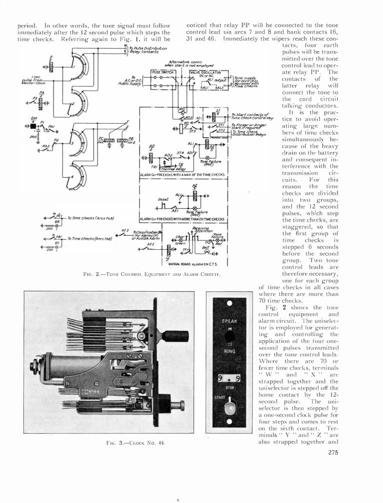
period. In other words, the tone signal must follow immediately after the 12 second pulse which steps the time checks. Referring again to Fig. 1, it will be
noticed that relay PP will be connected to the tone control lead via arcs 7 and 8 and bank contacts 16, 31 and 46. Immediately the wipers reach these con
IV tacts, four earth pulses ,,·ill be transmitted over the tone control lead to operate relay PP. The contacts of the latter relay will
--,---·-, ., ., g-V i 11>S�rtccn t<lct.sor 2 AE1 �I I Time Cl>tt:1< control�y '!f H.s.....-• I •
connect the tone to the cord circuit talking conductors.
It is the practice to avoid operating large numbers of time checks simultaneously because of the heavy drain on tht' battery and consequent interference with the
..ITL�I .._.,,.��:��"'"� -+l'"VJT_, . (""'•.:!!Lf-l 11> Tim• '-;J:;,_., . I L�Dlstril><ltxY>.<'elofl
!�.r iitrl�' I T°?3t!flure I Tilt (i � • r, �M C<T f'Ott EXCltS wmt A MAX Of" ZIO TIME CHECKS •
r-·-·-·-·--·� j ¥ I . !J!r'"· I+ I lle$el; , �... .
,.. Xt j AEI ��lure I .._....:::r-To Time Checlo(Arc.f 7&/J) �MCcr FOAUCllS WITHMOR£THANZlOTIMEtHE�· �� ·-,--·-- -·-· �, �� AE.J .\'>CW,,,�i'i T U<M1W> •
+/�/r-�.4Z I ��� ���I AE2 ° Green TF. b �· · .....,...... I t� • m Bell I
· TF j+ ' I T MAl«.W.. l!OAAO ALARM OH C.T s
F1G. 2.-ToNE CosTROL EQUIPMENT ANU ALARM CIRCUIT.
Fie. 3.-Ci.ocK No. 44.
transmi cuits. reason checks
ion c1rFor this the time
arc divided into two groups, and the 12 second pulses, which step the time chc-cks, arc staggered, so that the first group of time checks is stepped 6 seconds before the second group. Two tone control leads are the ref ore necessary, one for each group
of time checks in all cases where there are more than 70 time checks.
Fig. 2 sho\\ s the tone control equipment and alarm circuit. The uniselector is employed for generating and controlling the application of the four onesecond pulses transmitted on:r the tone control leads. \ Vhcre there are 70 or fewer time checks, terminals " \V " and " X " arc strapped together and the unisclector is stepped off the home contact b,· the 12-second pulse.
·The uni
selector is then stepped by a one-second cloLk pulse for four steps and comes to rest on the sixth contact. Terminal " Y "and " Z "are also strapped together and
275

relay PC is omitted. As the wiper on arc 3 steps round the bank, relay PB is operated four times and each time it operates, an earth pulse is transmitted over the tone control lead. This cycle of operation is repeated every 12 seconds.
FIG. 4.-INOIC.ITINC DRUM 1\ND CilMS.
In exchanges with more than 70 time checks, i.e., where each group of time checks is operated from alternate 6 second pulses, terminal " W " will be connected to the pulse serving the first group and terminal " X " to the pulse serving the econd group of time checks. In addition, both relays PB and PC will be provided to serve pulses to each group for operating the PP relays. The uni elector will therefore step every 6 seconds and relays PB and PC will receive four pulses every 12 seconds.
Minvtes Otm !110 Mmut• C,,,m I 0 ,
It will be appreciated that if the valve oscillator for any reason should fail to function, the subscriber would not receive any indication of the elapsed time thus giving rise to many disputed accounts. Arrangements have, therefore, been made for an alarm to be given in the event of failure so that the Traffic Staff may resort to verbal announcements. This is accomplished by inserting a relay AL in the plate circuit of the oscillator and arranging the circuit so that if the oscillator should fail the relay releases and provides an alarm. The alarm circuit, shown in Fig. 2, is a little complicated due to the fact that, in exchanges with comparatively few time checks, it is not desired to run the oscillators continuously when no calls arc being timed. It has been arranged, therefore, to start the oscillator directly a time check key is thrown by operating a relay, fitted with mercury tube contacts, to connect the main power supply to the oscillator. The valve oscillator alarm relay will take anything from 25 to 40 seconds to operate and it is necessary to delay the application of the alarm for this period. A thermal relay has been employed to give the necessary delay and it will commence to operate as soon as a time check key is thrown, i.e., when relay ST operates. The contact of the thermal relay, when operated, will energize relay AD and this relay will in turn, disconnect the thermal relay. The latter relay will release slowly and as soon as it reaches its normal position will transmit an earth to
contact ALI via ADI operated. Relay AL should in normal circumstances have operated by this time, but if for any reason
8 7 7
CORD CIRCUIT. (SLEEVE CONrROL). it has failed, the alarm extension relay, AE, will operate and the tone failure lamp will glow. Contact AE2 will operate relay
6 6 5 5 4 4 J J 2 2 I I 0 0 .SI ,
Notrl
SP 4
Notes.' /. Ope1>1tl!d 6y minute Ctm.,
Spr111;st1o21TN1keon9 .. 24-3 • •2.5•8
Ans·CorJd------r--
"' = 2. 0pe1>1ttd 6yJloAlti1vlrCa;,, Ans· SptT;ys415nuf,.on4U6tJt8'j I.Amp • S•6 • •81.9
• 5.6•7 • • 8 .
Note2 St.,rtKeyl ?, .
I
'f_J_.
� �SI¥ ToF/ickeror ''I'"""" A.....o- li'inger St4rt
(f f' r"'{l/I�) --·--·--·--·--· � ·--· '!I! .
276
T0Gs«;0<14�1o�. •· 1 l'romCAxk�I' •
Fie. S.-T1M1Nc C1Rcu1T, us1NG CLOCK No. 44.
TF on the manual board and its contacts will operate the bell and light the tone failure lamp. The Traffic Staff will note the receipt of the alarm signal by throwing the " receiving attention " key, disconnecting the bell. When the oscillator again functions correctly, relay AE will release and in turn release relay TF. The bell will again ring and the " clear " lamp will glow. The Traffic Staff will restore the " receiving attention " key, discon-necting the lamp and bell.
CLOCKS No. 44. One of the disadvantages of the Chargeable Time Indicator is that owing to the limited space available for accommodating the relay and uniselector racks its general adoption is not practicable at small exchanges. To overcome this difficulty a new timing device, which

can be mounted on the keyboard, has been developed jointly by the Automatic Electric Company and the Post Office. This timer has been given the rate book title of Clock No. 44 (Fig. 3) and consists of electromagnetically controlled cyclometer drums which display the chargeable time. The Clock assembly, together with a standard type lever key and a two position rotary key is mounted on a key plate 4-3; inches by 1 1/l6th inches. Two drums, each engraved 0 to 9, display the chargeable time in minutes and tenths of a minute up to a maximum of 9 minutes. The control key, with which is associated the resetting button, has two positions, namely, Start and Stop. With the control key rotated to the start position, depression of the resetting button is impossible, thus guarding against accidental restoration of the display during timing.
In the normal position the clock displays 9.9 minutes, the first impulse restoring the reading to 0.0. The object is to give the subscriber the benefit
Pawl Front Stop
Operating Pawl
of the first impulse, which may be anything up to 6 seconds.
The operation of the drums is on the reverse-drive principle. A ratchet wheel is attached to each drum and the armature is fitted with two pawls. One pawl engages with the ratchet of the tenth minute drum and the other engages with the minute drum on the completion of each ninth impulse. Attached to each indicating drum are two cams (see Fig. 4), one of which operates the spring combination for controlling the lamp and tone signals and the other, a heartshaped cam, functions for resetting.
To start the clock the operator rotates the control key to the start position, whereupon the clock commences to step due to the 6-second clock pulse being connected to the drive magnet (see Fig. 5). After 2.8 minutes, the tone control relay, PP, is connected by the operation of springs 2 and 3, 6 and 7. Relay PP then receives four pulses from the tone control circuit and each time it operates connects a tone to
Armature Back Stop ----
Restoring Pins Leather-faced Pole Piece
-�-Restoring Lever X -----U!-1.11--�;::::::��-��--l-_.
Heart - sha[Jed Restoring Cam
Detent Pawl
Pho¥hor Bronze �m ---��������������������������� Roller attached to cam Springs
Resrorin9 Plunger
Plunger quide Pin
Ro tary Start Key Knob
0
Detent Restoring Spring Plunger Restoring 5pring
Bal I for operating and locking Rotary . Key
!'m. 6.-CLOCK No. 44 MECHANISM.
277

/ / / .,,,.. ...... ( _.,,,,""'
/ \.... .......... \ I 0 ' I \
I I I I \ " \_ __ ..........
,o \ \
©\ ' I \ I
\ \ I
\ I ' l ) \
\.._.,) FIG. 7.-HE.\RT-�ll.IPEO C.\M AND LJo:VER.
the cord circuit. Relay PP is disconnected when the clock steps to 2.9 due to the opening of springs 6 and 7. The time check lamp glows due to the closing
and 8.8 minutes, but at the 9th minute relay SP operates to disconnect the driving magnet due to the closing of springs I and 2, 4 and 5. The operation of relay SP causes flicker earth to be connected to the time check lamp, the flickering of the lamp indicating to the operator that a ninth-minute period has expired and that the de,·ice should be reset for a further period of timing.
The resetting operation is accomplished by rotating the control key to the normal position, then depressing the plunger reset key. Referring to Fig. 6 it \\"ill be seen that the action of depressing the reset key lifts the operating pa\\"ls, ratchet and cam springs clear of the ratchet \\"heel and cams, whilst a lever engages with the heartshaped cams and restores the drums to the normal position (Fig. 7). Relay P is released and when the control key is again rotated to the start position the clock is ready to commence another C\"cle of 9 minutes if required.
·
The stepping of the clock is under the control of the originating s�bscriber's s\\"itch hook, the stepping of the clock be111g prevented \\"hen the receiver is replaced.
FIG. 8.-CLOCK 'o. 44 DISMANTl.ED.
of springs 2 and 3, 5 and 6 at 2.8 minutes. Springs 5 and 6 open at 3.0 minutes, thus disconnecting the lamp. The sequence of operations is repeated at 5.8
278
Fig. 8 sho\\"S the clock dismantled. It "·ill be seen that the start key and clock mechanism may be detached separately.

The New Liverpool-Glasgow Cable A. 0. GIBBON, M.1.E.E.
AN important underground scheme has recently
been completed betvveen Liverpool and Glasgow as the first part of a new West
Coast main telephone cable from London to Glasgow. The total length of the cable between Liverpool and Glasgow is 227 miles and it has been necessary to construct approximately 500 jointing chambers, 200 of which are required for the accommodation of loading pots.
In ordinary circumstances and apart from the provision of permanent repeater buildings, a work of this character would occupy a period of at least 15 months, but owing to the special circumstances of this case it was planned to complete the whole of the work within six months.
Between Liverpool and Lancaster approximately 10 miles of armoured cable was laid direct in the ground and approximately 42 miles of cable drawn into self-aligning ducts; between Lancaster and Carlisle the whole of the cable was laid in ducts, of which the main part already existed; whilst between Carlisle and Beattock more than 50 miles of armoured cable was laid direct in the ground and 4 miles of cable drawn into ducts. Between Beattock and Glasgow approximately 40 miles of armoured cable was laid direct in the ground and 16 miles of cable drawn into ducts. The lay-out of the route is shown in summary form in Fig. I.
The contract for the work was handled in approximately four equal sections by the undermentioned firms:-. (a) Liverpool to Lancaster-The United Tele
phone Cables, Ltd. (Northern). (b) Lancaster to Carlisle-Duct and manhole
work to the N orwest Construction Co. and the cables to Messrs. Pirelli-General, Ltd.
(c) Carlisle to Beattock-Messrs. Standard Telephones & Cables, Ltd.
(d) Beattock to Glasgow-United Telephone Cables, Ltd. (Southern).
It will be noted that in one section the duct and manhole work was carried out by the Norwest Construction Co., of Liverpool, and the cable work was done by Messrs. Pirelli. In the other sections Messrs. Standard Telephones & Cables carried out the duct and manhole work required in their own and also in Messrs. United Telephone Cables sections. The three companies operated separately, however, in trenching work for the armoured cable.
The type of cable laid between Liverpool and Lancaster is 360 pr/25 P.C. Quad + 4 pr/40 screened and from Lancaster to Glasgow 270 pr/25 + 4 pr/40 screened. A " target " view of the larger size cable is shown in Fig. 2. The lead-covered cable drawn into the ducts is of the Paper Core Quad type and its external diameter 2.70 inches.
A short description of the armouring of the cable
will be of interest. The continuously lead sheathed cable, after careful scrutiny for defects, is first passed through a bath of bituminous compound and immediately enclosed with lappings of compounded paper. The cable is again compounded and served with sufficient compounded jute yarn to form a bedding at least 0.06 of an inch thick. A compounded mild steel tape armouring 0.04 inch in thickness, on which
GLASGOW HAMILTO;•· 40�'.].�" ?S
CABLE IN CONDUIT·---
\ ARMOURED CABLE-· - • -
'-..__4,,40 Sc·+ 210,. ?5 UNITED TELEPHONE CABLES Lro ..------ 44 ·55.
(SOUTHERN) \ ��BEATTOCK
/ \...._______ 4,,,40 Sc. + 210,.. ?5
STANOARD �f"R/CJ"o•t I
5214"·
TELEPtiONES •CABUS LTD. ...... � "-\
\ Po. 4,. •os., .. ��o,.2s. e.-- I IS.
PIRELLI GENERAL LTD
UNITED TELEPHONE CABLES LTD. (NORTHERN)
LIVERPOOL
CARLISLE
I
Fm. 1.-LAv-ouT OF CABLE Rourn.
the compound has been allowed to set, is next applied to the cable with a suitable open lay, the gaps being not greater than 25 per cent. of the width of the tape. A similar tape is applied evenly over the gaps left by the first tape. A coating of compound is applied immediately after armouring. The armoured cable is then served with sufficient compounded jute yarn
279

'IRfT PAIRS IN LAY�Rl ( MARxL� ).
Norn.-The A, B, C, and D wires are denoted respectively by I, 2, 3 and 4 markings on the paper wrapping over the conductors.
Pairs 1-4 in the centre layer are used for broadcast circuits; pair 5-94 in layers I, 2 and 3 are used as 4-wire " goes " au�io and carrier; pairs 95-274 in layers 3, 4 and 5 are used as 4-wire audio; pairs 275-364 in layer 6 arc used as 4-wirc " returns " audio and carrier.
FIG. 2.-TARGET OF CABLE.
to form a covering at least 0.06 inch thick, and again compounded. The completed cable is white-washed to prevent adhesion between the coils of cable on the drums. The cable is finally coiled on wooden drums in such lengths as may be required. The external diameter of the larger size armoured cable is 2.98 inches.
The order to proceed with the work in the field was issued to all contractors during the week commencing 23rd June, 1934, but prior to that date, much preliminary work was required in connexion with negotiations with the Highway Authorities regarding the depth, course, and position of the cable and jointing chambers, the ordering and prompt delivery of the considerable quantities of stores from the Stores Department and the selection ana employment of supervisors of works to watch the operations on behalf of the Post Office. The setting out of the operations was arranged in such a way that completion of the whole of the duct and manhole work in all four sections would be reached by the end of August, also for the cable placing, jointing, and loading for the whole of the work between Liverpool and Glasgow to be completed by the third week in October, in readiness for acceptance tests of the completed cable and " lining up " of the amplified circuits in accordance with a pre-determined programme.
When the construction work in the field reached its peak load there were at least 1,300 men employed
280
between Liverpool and Glasgow and as a result of this exceptional method of dealing with an emergency, it is satisfactory to record that within approximately three months of the commencement of the work, the whole of the field operations were completed. It may be mentioned that of approximately 200 jointing chambers between Lancaster and Carlisle, many were constructed in the rocky or boggy ground over Shap Fell involving much difficult excavation work.
The cables are being partly loaded in the first instance by means of either manhole or buried types of loading pots and the cable jointing has been arranged in such a manner as will meet both the immediate and the ultimate loading requirements of the cable. The sheet steel type of pot is being installed in the manholes and an example of the pot supplied by Messrs. Salford Electrical Instruments, Ltd. (G.E.C.) for the Pirelli cable section between Lancaster and Carlisle is illustrated in Fig. 3. In
FIG. 3.-SllEET STEEL TYPE OF LOADING POT.
all the armoured cable sections a buried type of pot designed by Messrs. Standard Telephones & Cables has been installed and the general lay-out for immediate and deferred loading of the armoured cable is shown in Fig. 4. A view of the buried type of loading pot employed on the work is shown in Fig. 5, from which it will be observed that the case is of cast iron and the cable joint is housed within a cast iron protective cover,

PLAN
Cable Trench
')c.
Ground Level
l 2�s·--r-z:5•;
· _ _ I I Co11phn9Clli'lo -:JJ.,:-J�=:..::JIC��
P.C ConcreteR4ft
SECTION XX
FIG. 4.-LW-Ol'T Of' LOADING POIST.
At the principal repeater stations the main cable is terminated on " Tablets, Trunk Test, 24 circuit." These tablets, in conjunction with their 24 pr/20 lb. tail cables, afford a means of taking the paper-core cable direct to the test tablets. The incoming main cable is jointed to subsidiary cables at a main plug joint, and from each subsidiary cable a number of tail cables is taken. The " music circuits " are taken directly from the main plug joint by an independent tail. In this tail the pare pairs arc used as separators bet\\'cen the " music " pairs and are connected to the screens of the latter in the main cable. Fig. 6 shows a typical terminating arrange- FIG. 6.-T\'PICAL CIDLI' TERMINATION.
f1G. 5.-BURIBD LOADING POT IN SITU.
281

' ,. . .. ... I • .& MISIC
• . ,. I " - 11 i .. . ,. __l_ 11 . ...
IOI • , ,.
-��E� ... -� ... '1 n1 - ,...
- ...
.. _ ,.
An interesting view of the Post Oflice overhead line crossing Douglas :\foor is shown in Fig. 13. In this section of the route the wires "·ere, some 30 years ago, at the request of the \\"ayleave grantor, placed in a horizontal plane for a distance of approximately 5� miles in order to make the \\"ires less troublesome to game birds on the \\"ing. It is an unusual experience to meet with such a line in this country for the first time, departing as it does from all recognized standards of overhead construction.
"' - .. "' - "' m - Ml "' - ,..
FIG. 7.-L\\"-OUT OF TERMINATl01'S AT A REl'E,\Tlm ST.ITION.
ment and Fig. 7 illustrates the lay-out of the terminations at Beat tock.
There was exceptional activity on the part of the contractors during the week commencing 23rd June, 1934, and it is note\\"orthy to record that on the day on \\"hich the \\"Ork \\"as due to start, drums of cable were on site along the route crossing the Scottish hills. A number of photographs of the \\"Ork in the field \\"ill give some idea of its nature and the attendant difficulties. Fortunately the \\"Ork was started at a favourable time of the year, when long days and short nights ,,·ere the rule and good weather prevailed for most of the time, even in the Lake District. otwithstanding these fortunate circumstances authority \\"as given in one section to carry out cable placing continuously during both day and night in order to adhere to the programme of operations.
The grid power line running parallel with the Post Office overhead lines across Shap Fell is shown in Fig. 8. Figs. 9 and 10 are views of the underground work in progress some miles north of Beattock repeater station. Fig. 11 gives some indication of the rocky nature of the soil at Hamilton, in urban surroundings, in a section where self aligning ducts were laid, and Fig. 12 gives a fair idea of the general nature of the sub-soil excavated for the construction of manholes in open country.
FIG. 8.-SllAP FELL, SllOWING GRID LtNE.
282
Fig. 14 sho\\"S a trench excavating machine of the bucket type employed for the first time by tl lessrs . Standard Telephones and Cables on part of the route. 0\\·ing to the stony nature of the soil, hO\\·ever, the use of this machine \\"as greatly restricted. ,\n agricultural plough specially adapted for land drainage work ,,·as used on a section of the route. This machine greatly facilitated trenching in grass margins and on roadside \\"astes, but supplementary digging by manual methods ,,·as necessary in order to excavate to the required depth. The trench opene d up by the plough at times extended a mile ahead of the digging gang.
It is of interest to record that both Messrs. Standard Telephones & Cables and United Telephone Cables, Ltd. (Southern) conveyed the labour gangs
F1G. 9.-TRENCll EXCAVATION NEAR BEATTOCK.

Fie;. 10.-Cllll IXG IX l'HOGllE,,,, SF..\R B1(,\TTOCK.
FIG. 11.-fll.l'STR.\TES ROCK\" :'\\Tl:RF. OF Oll. AT 11.\MILTOS.
F1G. 12.-:"\ \Tl'RE OF t•n-�011. \T �l.\s1101.i-: Exc.,v.n1oxs.
to and from the Scottish hill country daily by motor coaches. Unless this course had been followed the companies could not have concentrated the required number of men for duty in these remote places.
F1e:. 13.-0vrn11E.\D L1 'iE c:1H1��1'ic Dcwc;r \� \loou.
. \ difficult and onerous construction work of this character has only been brought to a satisfactory conclusion in record time by reason of the strenuous and sustained endeavours of labour gangs, cable jointers, engineers and testing staffs ; and by reason of the full measure of co-operation, goodwill, helpfulness, and willing service rendered by Post Office and contractors' officials and also by the representatives of the H ighway Authorities.
283

A Simple Moving-Coil Microphone D. McMILLAN, B.Sc.
Summary.
THE work recorded in this article was originally
undertaken in order to produce a microphone suitable for use with Conference Telephone
Systems and Subscribers' Loudspeaking Telephones. As the investigation proceeded, it became obvious that the method of design adopted was capable of producing an instrument of better performance than was necessary for these particular purposes. The instrument, as finally designed, has actually proved to be of considerable general utility.
( 1) Introduction. Investigations have recently been undertaken at the
Post Office Research Station in order to perfect the design of a Loudspeaking Telephone of general application. It is intended that such a telephone will act as an adjunct to the normal subscriber's telephone, enabling him-when he so desires-to carry on a conversation with a distant subscriber by means of a remote microphone and loudspeaker unit. As the design of the system progressed, it became obvious that a special microphone was required to meet the particular requirements of the Loudspeaking Telephone.
The microphone to be used for this purpose must have a reasonably uniform frequency characteristic and must produce a minimum of " background noise." This latter requirement is extremely important, since speech currents from the microphone are used to operate a " voice switching " circuit. The design of this voice switching circuit involves the use of a two-valve amplifier in the microphone circuit. The instrument must therefore be sufficiently sensitive to send to line a speech power equal to that sent from an average subscriber's telephone when the microphone is used with a two-stage amplifier and spoken to in a normal voice from a distance of about two feet. Further, the arrangement of the apparatus used for Conference Telephone and Subscribers' Loudspeaking Telephone systems involves the use of a long connecting lead between the microphone unit and the amplifiers. The microphone must therefore be of a type which will function satisfactorily when so connected without involving the use of unduly large or fragile connecting wires.
It appeared probable that the majority of the above requirements might be met by the use of an electromagnetic instrument. Since the electro-magnetic instruments available on the market were either too costly for general use or unsuitable in performance, it was decided to design a simple moving coil microphone, using a permanent magnet to supply the necessary magnetic field in the air-gap. Such an instrument has the added advantage of needing no polarizing current.
284
(2) General Consideration of Moving Coil Microphones.
Consider any microphone of the moving coil type having a constant value of magnetic flux in the airgap. The e.m.f. generated in the moving conductor will then be proportional to the velocity of motion of the conductor in the air-gap. If the microphone is to have the same sensitivity at all frequencies, it is apparent that the velocity of motion of the coil caused by a sound of a given intensity must be independent of the pitch of the sound. It is necessary to investigate the exact nature of this requirement more closely :-
Consider a point P situated in a sound field set up by a source of sound of adjustable pitch. Let the sound pressure at P be independent of the pitch of the sound. If a moving coil microphone with uniform sensitivity at all frequencies is placed at the point P, the velocity of the coil of the microphone will be independent of the pitch of the sound. This will be so, despite the fact that the sound pressure at P is now no longer independent of the pitch of the sound -the sound field having been distorted (by the presence of the microphone of finite dimensions) t-0 an extent which will vary with frequency.
Normally there will be mechanical resonance of the suspension system of the moving coil, and the velocity of the conductor will not be independent of frequency for a constant applied alternating force. It will become smaller as the frequency is either increased or decreased from the resonance frequency.
There are two general methods of overcoming this difficulty in common use.
(1) The Mechanical Impedance of the moving system is made to be approximately constant over the required frequency range. This is usually attained by either,
(a) Reducing the mass of the moving parts to a minimum and swamping the variations of impedance by adding a relatively large, constant resistance ( " damping " the system) or (b), Coupling suitable resonators to the moving system so that the impedance of the combined system is less dependent on frequency.
It should be noted that it is still necessary to arrange that a sound of a given intensity results in an effective force upon the moving system which is independent of the pitch of the sound (i.e., the extent to which the microphone of finite dimensions distorts the sound field must be considered).
(2) The variations in sensitivity of the microphone, whatever their cause, are compensated by suitable variations in the gain of the amplifier used with the instrument.
Both these methods have been successfully employed in various designs of microphone. Method

(la) is not us�d to _any g
_r�at �xtent since it results
in a comparatively msens1t1ve mstrument. Wente and Thuras1 have used method (lb) with
considerable success. Their design, however, involves skilled assembly of small parts and the maintenance of small clearances to a high degree of accuracy. The instrument is therefore somewhat expensive to manufactu�e. . The Electric and Musical Industnes Co. have produced an instrument by application of method (2). It is understood that the instrument is constructed so that the suspension resonance occurs at about 500 cycles per second (c.p.s.). The resonance is f�ir�y well damped and the overall frequency charac�enstic of the microphone alone shows a slow nse _of sensitivity to this frequency
_ and a slow
_drop abo�� it.
This is compensated by a sUJtable electncal equahzmg circuit in the microphone amplifier. The damping of individual microphones is adjustable electrically to suit a fixed amplifier characteristic. Again, careful assembly is necessary and t�e amp
_lifier used :vith this
type of microphone is not 1mmed1ately applicable to other purposes. The instrument is relatively expensive.
A third method has been employed in the design of the microphone to be described.
The suspension resonance of the moving system is adjusted to occur at a frequency which is below the useful range. The moving system is then " inertia controlled " and the velocitv of the coil for a given applied alternating force is inversely proportional to the frequency of the applied force. 2 It is therefore necessary to arrange that the effective force applied to the moving system progressively increases as the pitch of the sound to which the microphone is exp.osed is increased. There will be a tendency for this to happen in any case due to the obstruction of the sound field by the microphone, but this effect is limited to a ratio of 2 : 1, as between high frequencies and low, frequencies.3 This is not sufficient and some further compensation must be arranged. It is provided in the design under consideration, by a suitable arrangement for access of sound to the back as well as to the front of the system. Thus, at low frequencies to which, by virtue of inertia control, the mechanical system is comparatively sensitive, the operating force is comparatively weak since it is due to opposing sound pressures which are nearly equal in magnitude and phase. As the frequency is raised and the mechanical system becomes less sensitive, the operating force becomes stronger because of the increasing difference in phase and magnitude of the opposing forces.
This method of design involves a straightforward and simple construction procedure. The suspension must be so designed that the resonance frequency is below, say, 60 c.p.s. A slight variation of the actual frequency for individual specimens is unimportant.
1 Journal of Acoustic Soc. Amer. Vol. 3, page 44.
2 W. West. Acoustical Engineering, page 25.
a Rayleigh, Theory of Sound, Vol. 2, Chapter 17; also S. Ballantine, Phys. Rev., Vol. 32, page 998 (1928).
This means that the construction can easily be adapted for mass production and a cheap item produced.
(3) Theoretical Consideration of the Method of Equalizing the Frequency Response of the Inertia-Controlled Microphone.
Sound is allowed access to the back as well as to the front of the moving system. The phase and amplitude of the sound pressures existing at the back of the system are controlled by adjustment of the shape and size of the microphone. It is therefore necessary to determine the obstructi?g eff�ct o� t�e instrument upon the sound field m which 1t IS
situated. This may most easily be done by considering the microphone as a sphere and modifying the results of the analysis to suit the particular shape involved.
Consider a rigid sphere, of radius r ems., situated in the vicinity of a source of sound. Then the intensity of sound will be different at various points on the surface of the sphere due to the presence of the sphere as an obstruction in the sound field. Rayleigh has calculated the magnitude of this obstructing effect4 and the following results are extracted from his analysis.
Let the source of sound be situated at a point A an"d let the centre of the sphere be situated at 0.
Then, a line drawn from A through 0 wil_l pass
through the surface of the sphere at two pomts B and B' where B' is on the side of 0 remote from A.
Consider any point P on the surface of the sphere and let the intensity of sound at this point be I.
Then, if cos POB = µ; Rayleigh shows that the following relations hold (to an approximation which is close for values of kr < t).
Whenµ + 1,
I 1 r+
Whenµ - 1, 1
I'= 4 +
Whenµ= 0, 1 I= 4
5 k2r2 + .77755 k4r4 + . ...
144
5 144
9
k2r2 + .02755 k4r4 + ...
k2r2 + .19534 k4r4 +
where k = 2rr -;- wave-length of the sound. . It will be seen that kr may be defined as the ratio
of the circumference of the sphere to the wave-length of the sound. . When kr is zero, the value of I becomes 0.25. This figure therefore represents, on the same scale, the intensity due to an unobstructed source of equal strength.
The directions µ = + 1, µ = - 1 and µ =:: 0 represent directions which may be defined by lookmg from the centre of the sphere in the direction of the source of sound, in the opposite direction and laterally, respectively.
4 Rayleigh, Theory of Sound, Vol. 2.
285

The difference in intensity at points B and B' (µ = + 1 and µ = - 1) may be expressed :-
I
,u=l µ=1 = i k4r4
The phase at any point is given by
I
3 ) tan e = kc \ - 1 + 2- fl
for a small sphere and for values of kc < t. Strutt5 has shown that these results, obtained from
the consideration of a rigid sphere, are also applicable to a circular plate-the axis of which is parallel to the direction of the incident sound-if the diameter of the plate is equal torr x r (r = radius of sphere).
The resultant force per unit area at the centres of plates of different diameters has been calculated from the above formulIB. The intensities in directions µ = + 1 and µ = - 1 were first found, together with the difference in phase in these two directions. The intensity figures \Vere taken as proportional to the square of a figure representing the sound pressure on some arbitrary scale and the resultant force per unit area found from a consideration of these pressure figures and the known phase difference between the pressure on the front and the pressure on the back of the plate.
The resultant force per unit area is plotted against frequency for three sizes of plate in Fig. 1.
It will be seen that for these sizes, the force is approximately proportional to frequency up to a frequency of about 1,000 c.p.s. Thus, if the microphone is designed to consist of a flat circular diaphragm suspended (by a membrane) in the centre
s Phil. Mag., Vol. 7, 1929.
of a flat circular plate of suitable diameter, the force on the diaphragm will be nearly proportional to frequency for low values of frequency. Then, with " inertia " control of the motion of the diaphragm, the velocity of the diaphragm for a given sound pressure will be almost independent of frequency.
(4) Practical Test of Method of Equalization.
A simple moving coil instrument Vias constructed consisting of a paper cone 6 ems. external diameter and carrying a coil of about 2 ems. diameter. The angle of the cone was approximately 120 degrees. This coil and cone combination was suspended so that the coil was free to move in a magnetic field derived from a small permanent magnet. The suspension was effected by means of a '' surround '' of thin leather attached to the outer edge of the cone and a centring '' spider '' of thin paper fixed inside the coil. Tests of the frequency characteristic of this simple microphone were made with various sizes of circular baffles. Fig. 2 shows one such curve for
8 !S. � "
i � 1' "
l .0 � 't; � I:: ;.-:; ., ., � "'
Ni
1·2
·8
·4
0 400 500 800 /OOO 1200 Fre<jueng - Cycle-s per second
FIG. 2.-FERQUENCY CHARACTERISTICS OF MICROPHONE MOUNTED IN BAFFLE-11 C.M.S. DIAMETER.
140�
o•rr::...---;;m� o--�20�0:--�.30�0--�40�0:--�sLoo=--�60Lo _ _ _ roLo�--e�oo _ __ 9 oio ___ mJo_o __ j
a baffle of about 11 ems. diameter. It is seen that the sensitivity of the arrangement is greatest at low frequencies and progressively drops as the frequency is increased. The irregularities in the neighbourhood of 600 c.p.s. and 800 c.p.s. are probably due to irregular performance of the paper cone at its edgewhere attached to the leather surround. The size of the baffle was reduced', by stages, until the curve of Fig. 3 was obtained. To reach this condition it was necessary to cut away all the baffle and leather '' surround '' and use the paper cone alone. Thi:> latter was suspended at its edge by three narrow strips of thin
Frequency - C_ycles per secono
Upper curve, r = 4.0 ems. ; Centre curve, r = 2.5 ems. ; Lower curve, r = 1.5 ems.
FIG. !.-RESULTANT FORCE/FREQUENCY FOR THREE SIZES OF PLATE.
286

\ \ v
-�
0 200 400
"'r--.._ � / i'-- �
600 /100 1000 /ZOO 1400
Frt!f/Venc_y - Cycles per second
1_........-L--
/SOO 1aoo �OOO
largely controlled by the paper centring spider. Later models, to be described, have a lower frequency of resonance.
F1G. 3.-FREQUENCV C111\RACTERIST1c o�· M1c1wp110NE w1T11 CONE ONLV--6 CMS. DIAMETER.
The above discussion has been limited to a consideration of frequencies below about 1,500 c.p.s. At higher frequencies, the diaphragm and suspension can no longer be considered as a simple system. A substantially uniform response up to considerably higher frequencies can, however, be fairly easily arranged by a suitable choice of angle of cone and material from which the cone is constructed. (Further reference to this point will be made in a later section of this article).
paper. (Fig. 4 shows the final arrangement). It will be observed, from Fig. 3, that the irregularities at 600 c.p.s. and 800 c.p.s. have disappeared and that the sensitivity of the microphone
..------------ --- ------
FIG. 4.-FINAL ARRANGEMENT OF CONE SUPPORTS.
is substantially constant between 200 c.p.s. and 1600 c.p.s. (It should be stated that the curves of Figs. 2 arid 3 have been somewhat smoothed in drawingminor irregularities having been omitted. The method of test employed for tracing the characteristics did not permit of an accurate determination of small dips and peaks in the curves). The leakage of sound from the front to the back of the diaphragm has compensated for the frequency characteristic of the inertia-controlled cone and coil suspension. The resonance of the suspension system of the experimental model occurred at about 80 c.p.s. and was
(5) The Use of a Small Moving Coil Unit for the Dual Purpose of Micropho11e and Loudspeaker.
It has already been stated that the design of a simple moving coil microphone was undertaken with a view to producing a simple instrument for use with Subscribers' Loudspeaking Telephones. Such a Loudspeaking Telephone will also require a small loudspeaker. It is well known that an inertiacontrolled piston, so mounted that access of sound from front to back is prevented, will radiate an amount of sound (for a given applied force) which is independent of frequency.6
Since the design of the microphone involves an inertia-controlled cone, it was thought that the same instrument might be employed for the dual purpose of microphone and loudspeaker. Such a small cone, with no " surround," as was used for the experiments recorded in the previous section (see Fig. 4) is unlikely to function efficiently as a radiator at low frequencies. The thin leather surround was therefore replaced and the instrument tested as a loudspeaker. Fig. 5 shows the low frequency end of the frequency characteristic obtained when the instrument was used with an effective baffle comprised by a complete box, the back of which was filled with Gamgee Tissue. It will be seen that the output is substantially constant from 200 c.p.s. to above 1,500 c.p.s. That this is so is taken as a justification for the assumption that the movement of such an instrument may be considered to be inertia controlled up to this frequency. The peak at about 50 c.p.s. is due to the suspension resonance and the dip at 100 c.p.s. is probably due to some absorbing effect of the wooden casing. In any case, the Loudspeaking Telephone will be used mainly for the reproduction of telephonic speech for which purpose circuit limitations render unnecessary a uniform response below 200 c.p.s.
In view of this result it was decided not to carry the equalization of the microphone to its logical limit by the removal of the leather surround, but to permit
6 W. West. Acoustical Engineering (pages 61 and 67).
.. 287

-JZ 0
I
I I(
.?00 400 600 800 1000 1200
Fre'iueng - cycles per secona' 1400
---
1600 1800
FIG. 5.-SOUND MEASURED ON AXIS OF Cou. AT 3 FEET FROM LOUDSPEAKER.
shape of the conical diaphragm and the material from which it is constructed are the main controlling features in this respect. The effect of the instrument in obstructing the sound field must also be taken into account. There will be a tendency for the force actuating the diaphragm to increase at the higher frequencies for a given sound intensity, but the range of increase is now strictly limited. Finally, a cone with an angle of 105°, constructed from a soft porous paper,
the sensitivity of the microphone to rise somewhat at the low frequencies. This rise may be almost completely eliminated by a suitable design of transformer for use with the instrument. It is then possible to specify the same simple moving-coil instrument for use as both microphone and loudspeaker.
This procedure, involving the use of a special transformer with the microphone, does not constitute a serious limitation for most purposes. However, should occasion arise where it is necessary to use a transformer with a uniform frequency characteristic to follow the microphone, there is no difficulty involved in modifying the design of the microphone to this end. This has already been demonstrated in the previous section.
(6) Final Choice of Design and Per/ ormance of Completed Instrnme11ts.
Fig. 6 shows the appearance of the instrument as finally designed. The frequency characteristic obtained from such a microphone up to a frequency of about 1,500 c.p.s. has already been discussed. The extension of the uniform characteristic to higher frequencies is mainly a matter of trial and error. The
F1c;. 6.-MOVING-COIL MICROPHONE.
288
was used. The thickness of the paper is about 0.01 inch. The " surround " of thin leather (termed " white split kipp ") is arranged to be quite slack. The coil is maintained in the centre of the gap by means of a paper " spider " constructed of paper 0.005 inch thick. Soft paper was chosen for the construction of the cone, because it appeared to exhibit higher modes of vibration than other materials tried (aluminium and hard paper) and allowed the useful frequency range of the microphone to be extended to higher frequencies. Details of the construction are shown in Fig. 7.
x
SECTION X X
FIG. 7.-LOUDSPEAKER UNIT.
The number of turns and gauge of wire on the coil were determined by the following considerations :
(I) The maximum amount of coppe� to be used having due regard to the ma111tenance of suitable clearances.
(2) The resistance of the coil to be suitable for use with long connecting leads.
(3) The self-inductance of the coil to be low. (4) The fixing of individual turns to be rigid.
It was assumed, in framing these considerations, that the same overall sensitivity of microphone and transformer combination could be obtained for all possible arrangements of a given mass of copper on the coil. Practical difficulties of transformer design will obtrude if the coil resistance is made excessively low or high.
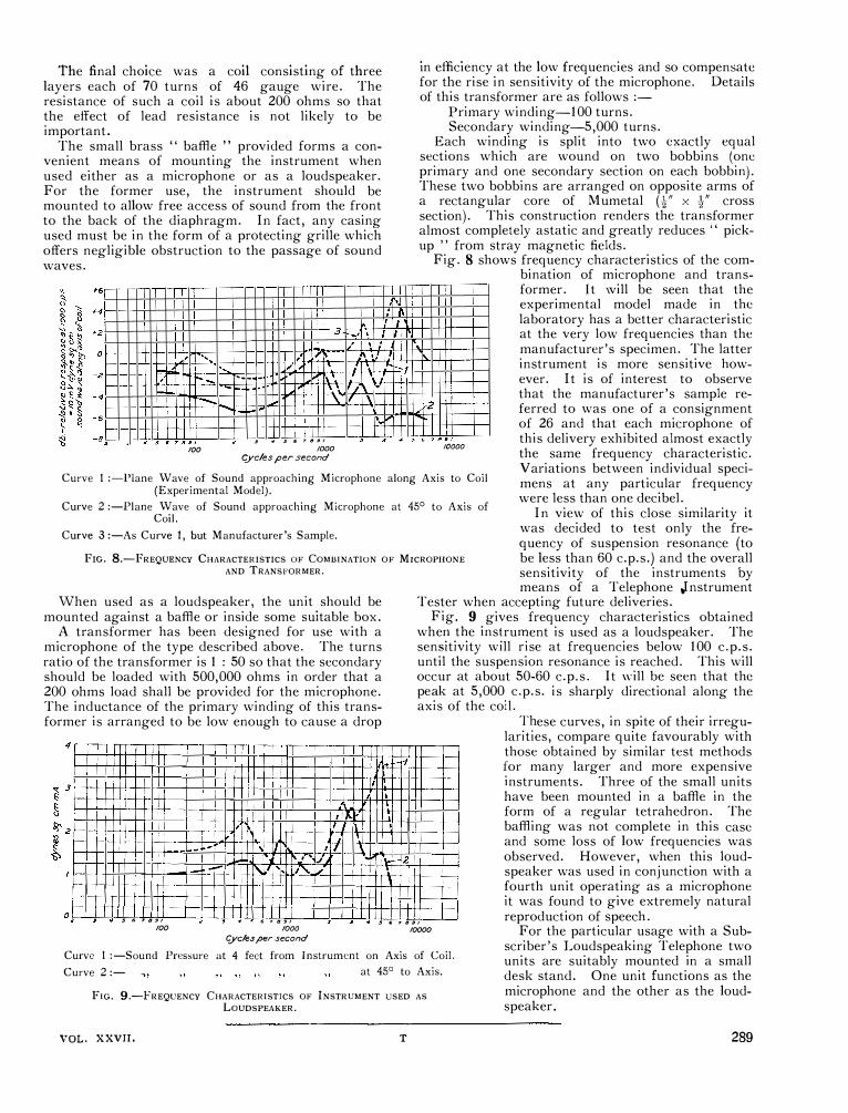
The final choice was a coil consisting of three layers each of 70 turns of 46 gauge wire. The resistance of such a coil is about 200 ohms so that the effect of lead resistance is not likely to be important.
The small brass '' baffle '' provided forms a convenient means of mounting the instrument when used either as a microphone or as a loudspeaker. For the former use, the instrument should be mounted to allow free access of sound from the front to the back of the diaphragm. In fact, any casing used must be in the form of a protecting grille which offers negligible obstruction to the passage of sound waves.
"' 3r---:, ' , I
, ., , '• , �'-' - "·" \ : '.
, ,__ ... __ - Ii , . � --- ,. ' �- .
-..... \ ·' \ ·-f-
, . ' 1 ll
I
'
f-- I
,
100 .!I 4 5 6 7 8 SI
!OOO «Ycles per second
-
r.
in efliciency at the low frequencies and so compensate for the rise in sensitivity of the microphone. Details of this transformer are as follows :-
Primary winding-100 turns. Secondary winding-5,000 turns.
Each winding is split into two exactly equal sections which are wound on two bobbins (one primary and one secondary section on each bobbin). These two bobbins are arranged on opposite arms of a rectangular core of Mumetal (t" x t" cross section). This construction renders the transformer almost completely astatic and greatly reduces '' pickup " from stray magnetic fields.
Fig. 8 shows frequency characteristics of the com
�2 'I
10000
Curve I :-Plane Wave of Sound approaching Microphone along Axis to Coil (Experimental Model).
bination of microphone and transformer. It \vill be seen that the experimental model made in the laboratory has a better characteristic at the very low frequencies than the manufacturer's specimen. The latter instrument is more sensitive however. It is of interest to observe that the manufacturer's sample referred to was one of a consignment of 26 and that each microphone of this delivery exhibited almost exactly the same frequency characteristic. Variations between individual specimens at any particular frequency were less than one decibel.
Curve 2 :-Plane Wave of Sound approaching Microphone at 45° to Axis of Coil. In view of this close similarity it
Curve 3 :-As Curve 1, but Manufacturer's Sample. was decided to test only the fre
FIG. 8.-FREQUENCY CHARACTERISTICS OF COMBINATION OF MICROPHONE AND TRANSFORMER.
quency of suspension resonance (to be less than 60 c.p.s.) and the overall sensitivity of the instruments by
When used as a loudspeaker, the unit should be mounted against a baffle or inside some suitable box.
A transformer has been designed for use with a microphone of the type described above. The turns ratio of the transformer is 1 : 50 so that the secondary should be loaded with 500,000 ohms in order that a 200 ohms load shall be provided for the microphone. The inductance of the primary winding of this transformer is arranged to be low enough to cause a drop
4
I I
; I 1',
, I � '
- - . •II
.-/
I I
' .. ' 'J ·LI- 2 - - l'-L' ' , , I. �
I I
, , . I 5 6 7 B !JI
0
I
, 3 . 5 6 7 8 �I 2 5 6 7 8 SI
means of a Telephone Jnstrument Tester when accepting future deliveries.
Fig. 9.
gives frequency characteristics obtained whei: .
t�e ms�ruH?ent is used as a loudspeaker. The sen�1tiv1ty will r�se at frequencies below 100 c.p.s. until the suspension resonance is reached. This will occur at about 50-60 c. p. s. It will be seen that the pe�k at 5,000
. c.p.s. is sharply directional along the
axis of the cod. T�ese curves, in spite of their irregu
lanties, compare quite favourably with those obtained by similar test methods �·or many larger and more expensive mstruments. Three of the small units have been mounted in a baffle in the form of a regular tetrahedron. The baffling was not complete in this case and some loss of low frequencies was observed. However, when this loudspeaker was used in conjunction with a �ourth unit operating as a microphone it was found to give extremely natural reproduction of speech .
100 1000 t;yc!es per second
10000
Curve I :-Sound Pressure at 4 feet from Instrument on Axis of Coil.
For the particular usage with a Subscriber's Loudspeaking Telephone two units are suitably mounted in a small desk stand. One unit functions as the microphone and the other as the loudspeaker.
Curve 2 :- at 45° to Axis.
FIG. 9.-FREQUENCY CHARACTERISTICS OF INSTRUMENT USED AS LOUDSPEAKER.
VOL. xxvn. T 289

Ashton-in-Makerfield Telephone Exchange
A. S. CARR, M.A., M.l.E.E., and
R. HUMPHREYS
THE new exchange at Ashton-in-Makerfield is
the first satelite to be connected to Wigan. It was opened on Saturday, the 1 st September,
1934, and embodies so many new features in the design and method of automatic telephone switching that an attempt has been made in the following notes to show some of the important developments which have been put into practice in its construction.
Buildings erected in the township of Ashton-inMakerfield are liable to be adversely affected by subsidence due to the labyrinth of excavated coal seams which abound below this part of Lancashire : a fissure on the site was actually noticeable and it was decided to alter the lay-out of apparatus and put up two small buildings joining them by means of a wooden corridor. This expedient distributed the weight fairly uniformly. One portion houses the apparatus and the other the power plant, and in the corridor are reasonable bights in the cables to allow of a fair settlement without disconnexion.
The equipment was installed by the Automatic Electric Company and is known as Type No. 32A. It incorporates the standard British Post Office line finder system, suitable for working in conjunction with the common control apparatus which is installed at Wigan. The equipped capacity is 260 lines with a 300 multiple, the ultimate capacity being 500 lines.
Fig. 1 shows the trunking diagram and it will be
FIG. 1.-TRUNKING DIAGRAM.
noted that discrimination can be effected to route the call to (a) the main exchange, (b) manual board (" 0 " Level) and (c) the numbers in the local area.
290
If necessary, by a simple addition, discrimination can also be given to other satellite exchanges.
Unlike the standard method where discriminating selector repeaters are used, the apparatus installed at the Ashton-in-Makerfield exchange has the special feature whereby it is released immediately the discriminating digit has been dialled, with the result that only a small amount of this type of equipment is required. The discriminating feature employs the following apparatus :-2 start relay-sets, 2 allotters, 4 discriminating relay-sets, 4 uni-selectors, 4 primary hunters, 4 junction hunters (A), 4 junction hunters (B); and whichever part of it is in use is released immediately the discrimination has been effected. The amount of apparatus provided is, of course, a minimum and many more lines could be satisfactorily handled without additional equipment. A 30-secoml delay pulse releases the discriminator and connects the subscriber to N. U. tone if he fails to dial the 1 st digit within that period.
The subscriber's loop causes the line finder equipment to test for a free discriminating relay-set. Normally the allotter preselects an idle D.R.S., but if this preselection has not taken place, conditions are set up which cause the allotter magnet to be energized with the result that the wipers are rotated to find an idle D.R.S. When one has been found, the primary hunter drive magnet is brought into operation causing its wiper to hunt to find a marked contact set up by the line finder equipment. Simultaneously the driver magnet of the junction hunter (A) is energized to test for and seize an idle main exchange relay set unless the wipers are already standing on a free one. The subscriber's loop is then extended via this primary finder and the primary hunter wipers to operate the A relay in the main exchange relay-set. Dial tone is also connected over the negative line to the calling subscriber.
On receipt of the first train of impulses, the discriminator steps : the impulses are also repeated via the junction to step the selector at the main exchange.
If the main exchange has been dialled, the conditions given by the discriminator to the main exchange relay-set will cause the associated group finder to hunt for a marked contact in the group finder bank. The circuit is so arranged that only one common relay in the groups of discriminators can be operated at once. Hence only one group finder hunts at a time. On the group finder being seized, the main exchange relay-set is extended to the calling line and the remaining trains of impulses are repeated to the main exchange.
When the relay-set has switched through to the calling line, a release condition is returned to the discriminator, which, upon restoring to normal, is free to be preselected in readiness for the next call.

Local calls and provi ion of busy and N. U. tones are dealt with similarly with the exception that junction hunter (B) is used for these routings. It is interesting to note that the banks of these junction hunters may be divided and associated with various relaysets, thus increasing the possible selection.
1\lulti-metcring is al o incorporated in this system. The main exchange relay-set can cater for local and three unit fee areas, metering being affected by a meter pulse relay-set, as in Fig. 2. It is unnecessary
•
�����""�JG.�����-.� C&
F10. 2.-MULTl-IJETERING.
to have separate groups of line finders for coin boxes as distinct from ordinary lines: the former arc connected to battery and the latter to earth ; the connexions for these are made by means or straps soldered in a special connecting strip attached to the meter rack.
The exchange is fitted throughout with single-sided racks to which all multiple banks are rigidly fixed. This unique feature has made possible the use of twomotion switches of the jack-in type. These may readily be removed from service and restored without the aid of a bank spanner. The necessity for the usual wiper adjustments is thereby reduced to a minimum. The switches themselves differ from the usual design, being much smaller than the standard
200J1 =<>A
� '2 ..,
.. oon i .. oon
...... .. oo.n
<! 9
•h.
F10. 3.
type. This enables a re-allocation of the space at the side and back of the switch. The magnet coils have been reduced to two and each has only a single coil. The magnets are self-protecting; require less current than the standard types; and arc more robust.
The wiper carriage of the selector slides and rotates on a fixed shaft supported at both ends : the mechanism is independent of the bank capacity which, if necessary, could be extended in multiples of I 00 to 800. This also allows fourth-wire metering in line finders and simplifies the connexion of P.B.X. final selectors.
One of the most interesting features of the system is the absence or a " Z " or release magnet. On the release of the holding relays, a circuit is completed to re-energize the rotary magnet, which causes the wipers to step clockwise to the 12th step, i.e., out of the bank on the right, down, and back to their normal position under the tension of the carriage restoring spring, see Fig. 9.
The start set of the primary line finders now makes use of thermionic valves. All directly connected primary line finders in the same group are connected to the grid of valve "A " and all indirectly connected primary line finders in the ame group are connected to the grid of valve '' B.'' So long as any one of the directly connected switches is disengaged, a battery
F10. 4.-LINE FINDER RACK.
291

engaged the relay operates and relay RFZ is shunted down. 'When relay RFZ releases, the filament circuit of valve " B " is completed and the valve is brought into service to test the indirectly connected finders. When all indirectly connected primary line finders are engaged, there is an absence of battery on the grid of valve B, and relay 01'B operates : the start lead is then connected to the overflow meter on which further calls from the group will be recorded, sec Fig. 3. In this particular case, all primary line finders are indirectly connected.
Fig. 4 gives a close-up view of the line finder rack. It shows the banks of subscribers' lines (C}, primary L.F. allotters (B) and the
f1G. 5.-LINE FINDER, FINAL, AND GIWUP SELECTOR!>. start and control sets of the line finders: the valve in the O.F.B.
potential will be present on the grid of the valve, which will prevent the operation of relay RFB, but as the directly connected primary line finders become
FIG. 6.-flNAL SELECTOR RACKS. 292
(overflow) circuit can be seen and also the 3,000-type relays with their white buffer blocks. The keys for routining line finders on various levels on the right and the new type of vertical dog
in the form of an eccentric disc is particularly clear below the HB relays.
Fig. 5 illustrates the line finders, final, and group selectors. The two 2-
pin markers fit into two levels of jacks, enabling the switch lo be busied or held on vertical or rotary without release \\'hen \\'i thdra wn.
Developments haYc abo been extended to the interrupter springs of the primary line finders and selectors. The magnets of these switches are energized through '' toggle 11 springs, the mo,·ement of which is controlled in both vertical and rotary lcps by forward and back\\'ard limit �tops on the armature in their operation and release. The moving " toggle " �pring is designed so that it continues its travel after passing through its own centre line and the stops which arc placed equidistant from the centre line allow definite operation and reliable contact pressure. The required tension is provided by means of a trigger spring.
Fig. 6 shows the final selector rack and general lay-out of the apparatus. The floor covering, used for the first time in an automatic exchange, is of green marble coloured rubber and tones well with the light green paintwork.
Further interesting features worthy of mention arc the permanent loop alarm to the main exchange and the N. U. tone to spare line . When all B. and N. U. lone relay sets are engaged

FIG. 7.-GROUP Al\0 Fll\AL SELECTOR RACKS.
the discriminator will route all P .G's to the local group selectors, a suitable alarm being given to the main exchange when the number reaches a certain value. An ordinary ammeter is used for the purpose; the alarm is set by a pointer which moves over the scale in much the same way as that used for high and low volts. This " P .G." meter can be seen in Fig. 6 mounted near the fuse alarms and meters.
The usual jumpering scheme for spare lines on
=
·-1------ ---
1Cl'SA. •
I
-
I
I �TON·111-Y!,t,«QF1"1.0 '
I j i8JTWl5111SSIOr< !)e!DGI:
F1G. 8.-TRUNK 0FFl!RING ANO TRUNK TRAIN FACILITY.
the M.D.F. has been discontinued. A new type of connexion strip is mounted on the final selector rack upon which the multiple banks terminate. Strips are provided with an additional row of tags common to the N.U. tone supply and by means of short straps the tone is connected to the negative lines of all spares on the final selector multiple banks.
These connexion strips can be seen on the extreme right of Fig. 7 which also shows the backs of the group selectors including four with trunk train facilities on the bottom left.
The panllel access of Manchester and Wigan into Ashton-in-Makerfield, see Fig. 8, is as follows:-
Both have access to I st selectors at \Vigan which are teed : these in turn route the calls through relay-sets to Ashton.
\Vigan, in addition, has direct access to the relay-set from another and similar set of jacks to which the last three digits only are dialled.
The group selector (Fig. 9) handles the incoming trunk call in the following manner :-On being seized, relays A and OC operate; A operates B which completes a circuit for C to battery and for TO through contacts of OC to the rotary magnet. When C operates it prepares a circuit for relay CN. Relay AO in operating locks itself from earth via B operated.
Vertical Motion : Before the receipt of the first train, the earth on the positive is replaced by a loop and OC releases with windings in opposition.
Relay A responds to interruptions of the line loop and V steps in the usual way, i.e., with C slug operated over the 3-ohm winding in series with the V. M. pulses.
Relay B holds due to its own slug and the wipers are raised to the level dialled.
Rotary Motion: After C's delay period, it releases and sets up the circuit from the rotary magnet to earth at LK2 : the testing circuit to the P-wiper is also made via relay LK in series through the 800 N.I. spool and relay H in parallel to earth. The rotary operation takes place as usual depending on the condition of the outlet-disengaged or engaged.
If free, a 3000 battery will be present on the P bank contact; thus the fast operating testing relay LK, functions and stops further rotary movements.
'
If engaged there is no circuit for LK and the wipers step forward.
Switching to free outlet : Relay LK in operating :
(a) Breaks the rotary drive. (b) Short circuits the 1500 winding and puts a
120 busy on the private. (c) Allows relay H to operate which locks to
battery at R.
293

lD.F. _!::':-��·D��---���������--..:;...--������������---,�--;::::;---<> H
t 1)1�111� Q W2 QA I
I '""" ""'""" F'
·��l i lso 'l?F, CN
.:All�I� QB WI
LI( ri 5
; Id I � u: {:!
�] ·� HOLO SD W?>
. � \-+ � F 1l!l TO
:�l ! t: �:PER�
MULT so
5 YC 400
T .. oc 1::}1� .
B H W4 r::.__::,,,�
oc
MEiCR., FIG. 9.-GROUP SELECTOR FOR TRUNK TRAIN.
Relay H puts the lines through to the wipers and provides for (a) the operation of C, (b) this operates F and (c) the holding of B against the release of relay A.
Relay C, in operating, breaks LK's testing circuit and prepares circuit for CN and SD.
Relay F prepares busy flash and tone, also circuits for busy hold and D. Further digits now pass ahead and the positive and negative lines are switched clean into the final selector. The group selector is held by its LK holding to the 3000 battery on the P-wire. Relay B is held by H which is locked and now dependent on LK's release.
Required subscriber free : Relay H in the final selector operates and puts battery back on SW via contacts of H2 or TO to SD and earth. SD operates, completes a locking circuit clear of H, and TO puts earth on P and prepares a circuit for CN and release circuit of F.
Relay LK releases, and releases H which transfers the lines from the final selector to the selector A relay. Relay CN operates for ringing and ring return circuits: so also does A to hold relay B.
The holding of the train is now controlled by A. Relay SD is held to the final selector H relay.
Ringing of required subscriber : This is controlled by the operator's ring key and OC operates due to unbalance. The return of F, due to short circuit of the 4000 winding, connects ringing to the negative wiper and ring tone to the calling side.
Subscriber's Answer : Relay F operates, locks and connects the called subscriber's loop to relay D which operates to reverse the battery to the calling side to give supervision.
Release is controlled by the operator who releasing A, B, TO, CN, F and C, causes an earth to short 294
circuit SD. The rotary circuit is then again completed and the switch released.
Required subscriber engaged : The final selector puts earth on the P lead which allows LK to release. Relay LK and H function as before and the final selector provides a condition which allows relay H to operate. The position now reached is that of busy flash and tone are connected to the calling side and busy hold to the B relay. This holds the final selector H relay and the lines of the required subscriber are connected through to the group selector, but are disconnected at this point.
Busy flash and tone indicate that the subscriber is engaged and the trunk call is offered. (Toneless flash is given if the outlets are engaged). This is effected by the unbalancing of the incoming line which allows OC to operate. Thus from earth B, OC, TO operated, SD normal, winding of CN, C op, N op, R int, R magnet to battery, relay CN operates and connects lines to condensers, allowing a speech path between operator and required subscriber.
Relay D arranges for supervision to the operator and SD's circuit is prepared. Busy flash and tone are removed. Immediately earth is taken off the required subscriber's call off relay (normally controlled by calling subscriber) the circuit for SD is effective and SD operates. Relay D is then connected to the negative and positive wipers and through to the required subscriber. Relay D releases if the subscriber has cleared and gives a clear to the operator. The operator then uses the ring key and ag�in operates OC. Re-ring facilities are provided.
In conclusion, the authors wish to express their thanks to the Automatic Electric Company, Mr. Phillips and Mr. Fazackerley.

England-Australia October 20th,
Air Race, 1934
DURING the latter half of October, the England
Australia Air Race in connexion with the Melbourne Centenary occupied no little space
in the Press, so that some account of the Post Office special arrangements in this connexion may be of interest.
Preliminary intimation was received during the first week in September, 1934, that the Royal Aero Club had arranged with the Air 1\linistry for the race to start from Beck Row Aerodrome, near Mildenhall, in the Cambridge Engineering Section. Attempts were immediately made to ascertain what Post Office services would be required, and after various conferences between the Air Ministry, Royal Aero Club, and the Post Office, it was finally decided on September lSth to establish a temporary Post Office with full Postal, Telegraph, and Telephone facilities, including 12 trunk circuits, two local post-payment Call Offices, and four Teleprinter circuits; a room approximately 7S ft. x 2S ft. being loaned by the Air Ministry for this purpose. As the office was due to open at 8.0 a.m. on the 13th October, this left barely four weeks for the requirements to be met.
Figs. I and 2 show, respectively, the building set apart for the Department's use and the interior with the Post Office plant installed.
FJG. 1.-TllE TEMPORARY POST 0FFICI!.
From the initial requirements it was apparent that the local plant available would be entirely inadequate to meet traffic demands, both from a telegraphic and telephonic point of view. Two temporary I.R.V. aerial interruption cables were therefore erected from the Aerodrome-one (8pr /20) to the local Telephone
w. M. OSBORN, A.M.1.F.E.
Exchange at Mildenhall (31 miles), and the other (19pr/20) to the main London-Norwich overhead trunk route at Barton Mills (4� miles). The cables were run on any convenient supports such as treetrunks and poles, and also in ditches and alongside hedges wherever possible. At road crossings the cables were suspended by means of galvanized iron wire and thick twine, whilst at gate crossings the cables were buried approximately 2 ft. in depth.
The whole of the trunk circuits were terminated 10 + so . .
on a 6S
P.B.X. sw1tchboard-w1th the excep-
tion of the two post-payment Call Offices, which were connected direct to the local Exchange. Eight standard telephone cabinets, fitted with the latest pattern microtelephones and extra watch receivers, were provided for trunk calls and connected to the switchboard as extensions-the extra receivers being provided to eliminate noise, due to aeroplanes tuning up, etc., as much as possible. All the cabinets were arranged in suites in the public section of the office, in such a position that they could be viewed from the switchboard which was placed at the end of the counter.
The four Teleprinters and one reserve machine were arranged on a table in the centre of the room
FIG. 2.-INTERIOR OF POST OFFICE.
at the rear of the counter to reduce to a minimum the time of transmission after messages had been handed in. The power for these machines was obtained by means of dry core rectifiers from the Aerodrome supply of 230 volts A.C. SO cycles-a portable reserve battery being installed in case of breakdown. The
29S
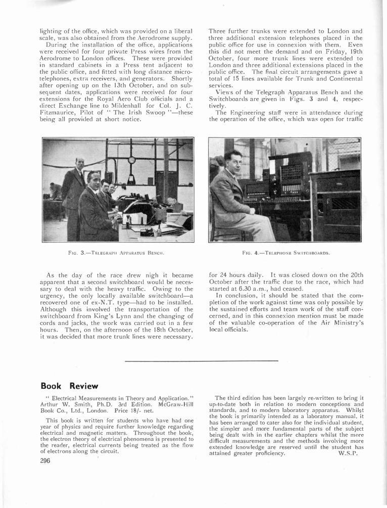
lighting of the office, which was provided on a liberal scale, was also obtained from the Aerodrome supply.
During the installation of the office, applications were received for four private Press wires from the Aerodrome to London offices. These were provided in standard cabinets in a Press tent adjacent to the public office, and fitted with long distance microtelephones, extra receivers, and generators. Shortly after opening up on the 13th October, and on subsequent dates, applications were received for four extensions for the Royal Aero Club officials and a direct Exchange line to l\fildenhall for Col. ] . C. Fitzmaurice, Pilot of " The Irish Swoop "-these being all provided at short notice.
FIG. 3.-TELEGRAPll APPARATUS 8ENCll.
As the day of the race drew nigh it became apparent that a second switchboard would be necessary to deal with the heavy traffic. Owing to the urgency, the only locally available switchboard-a recovered one of ex-N.T. type-had to be installed. Although this involved the transportation of the switchboard from King's Lynn and the changing of cords and jacks, the work was carried out in a few hours. Then, on the afternoon of the 18th October, it was decided that more trunk lines were necessary.
Book Review
" Electrical Measurements in Theory and Application." Arthur W. Smith, Ph.D. 3rd Edition. McGraw-Hill Book Co., Ltd., London. Price 18/- net.
This book is written for students who have had one year of physics and require further knowledge regarding electrical and magnetic matters. Throughout the book, the electron theory of electrical phenomena is presented to the reader, electrical currents being treated as the flow of electrons along the circuit.
296
Three further trunks were extended to London and three additional extension telephones placed in the public office for use in connexion with them. Even this did not meet the demand and on Friday, 19th October, four more trunk lines were extended to London and three additional extensions placed in the public office. The final circuit arrangements gave a total of 15 lines available for Trunk and Continental services.
Views of the Telegraph Apparatus Bench and the Switchboards are given in Figs. 3 and 4, respectively.
The Engineering stafT were in attendance during the operation of the office, which was open for traffic
FIG. 4.-TELEPllONE SWITCllBOARDS.
for 24 hours daily. It was closed down on the 20th October after the traffic due to the race, which had started at 6.30 a.m., had ceased.
In conclusion, it should be stated that the completion of the work against time was only possible by the sustained efforts and team work of the staff concerned, and in this connexion mention must be made of the valuable co-operation of the Air Ministry's local officials.
The third edition has been largely re-written to bring it up-to-date both in relation to modern conceptions and standards, and to modern laboratory apparatus. Whil t the book is primarily intended as a laboratory manual, it has been arranged to cater also for the individual student,
the simpler and more fundamental parts of the subject being dealt with in the earlier chapters whilst the more difficult measurements and the methods involving more extended knowledge are reserved until the student has attained greater proficiency. W.S.P.

Telephone Week at the London Trunk Exchange
WHEN the Postmaster-General announced
that after 7 p.m. Trunk calls could be made to any part of the British Isles for 1 /-, it
was evident that a great increase in evening traffic would result, especially in view of the wide publicity given to the telephone service during Telephone Week. The difference then existing between the evening conditions and the morning '' busy-hour '' was, however, so great that a sufficient margin of safety appeared to exist, and, so far as the London Engineering District was concerned, it was felt that the chief effect of the reduction in charges would be to prevent evening routine testing of repeatered circuits, and to necessitate an extension of the exchange maintenance staff rota to twenty-four hours.
It soon became evident on Monday, lst October, that the reduced and uniform charge was appreciated by the public even beyond anticipation, for shortly after 7 p.m. the switchboard was ablaze with light as subscribers competed with each other to obtain their " shilling's worth." This condition is clearly seen in Fig. 1, which represents the discharge
500 450 400 "
I/ \ '
"'"" j ""-�350
�300 �250 �200 � 150
I r\ I \. I , \
j \J
100 7 ...
...... � 1.,...-17 -
circuits, in fact all lines over which reasonable transmission could be obtained, were commandeered. The transmission aspect was important, as the public are now accustomed to a high standard. To have rushed in low grade circuits would have been sheer waste of time and would only have given rise to complaints.
Obtaining the circuits was, however, only half the battle-there still remained the difficultv of connecting them to the switchboards, so that they could be used for traffic. For inland calls, the London Trunk Exchange consists of no less than 305 positions, situated in four different rooms, each room being provided with a separate multiple. To connect the new circuits at the end of the normal groups in these multiples meant joining up relay-sets, one of which is necessary at each end of a trunk circuit under the sleeve control system, jumpering to the various multiples, modifying the Visual Idle Indicating Equipment and altering the labels. Also, in cases where sufficient spare jacks did not exist at the end of the normal group, other groups of circuits had to be moved to make room. All this work needed time, and time was precious, since the new circuits had to
,._ I\.
'
\:
\ ' 50
0 MID•
NIGHT 5 10 NOON. .3 8 MID
NIGHT
be ready for the rush of traffic anticipated on the following evening. Difficulties, however, are made to be overcome and the solution of this one lay in connecting a number of jacks over the Straightforward Junction Positions to relay-sets jumpered to the Trunk Test. These terminations formed a " pool " to which each new circuit was " patched " immediately it became available. Since every operator has access to the straightforward junction positions, the new circuits were available to all with an absolute minimum of delay.
A.M ----- TIM£ �----- P.M
FIG. 1.-TRUNK EXCHANGE BATTERY; DISCHARGE CURRENT, IST OCTOBER.
current of the Trunk Exchange battery. Bearing in mind that this curve includes current supplied to the International Exchange, which did not participate in the evening rush of traffic, it is evident that the Inland Trunk Exchange had to face the sudden application of a load equal to, if not exceeding, that d�ring the busiest period of the morning. Before this deluge of calls, of which a large proportion was confined to the long distance routes, the Demand �ystem had, perforce, to give way to Delay Workmg.
Strenuous efforts were made by the Traffic Staff to deal with t�e new conditions, but. that, as Kipling would say, 1s another story, the object of these notes bein?" me:ely t� re�or? the p�rt played by the London �ngm�enng D1stnct m meetmg the emergency. The immediate cry was for more lines, more lines at once and to meet this need aerial reserves, experimental
.To obtain additional lines, the L.T.S. arranged with the renters of private wires to release them for traffic purposes in the evening. These circuits also were '' patched '' into the pool by cords at the Trunk Test Position, which, as can be seen from Fig. 2, ultimately resembled the after-math of a severe snowstorm in the old days of the aerial Trunk system. �s a result of t
_hes� efforts, n� fewer than 28 long
distance trunk circUits were available for traffic within twenty-four hours.
On Tuesday evening the traffic was even heavier than on Monday, and, although the efforts which had been made enabled the completed calls to rise from 67.5% to 74% of the total bookings, it was evident that the new conditions were not a mere flash in the pan, and that the efforts to provide additional plant must be pushed on at high pressure.
More and more circuits were obtained from spare
297

week, the total route mileage involved being approximately 20,000 miles. The circuits had all been connected in their proper groups in the multiples, except in the Provincial Exchange, where an extension of the multiple had just been completed and where a complete rearrangement was necessary. In addition, the part-time circuits (Private Wires, Telex Circuits, etc.) had been connected on the Trunk Test Desk to the " break jack " scheme, permitting their being taken into use for traffic purposes simply by moving insulating pegs and thus avoiding a multiplicity of " patching " cords.
FIG. 2.-" PATCHING " CORDS AT TRUNK TEST POSITION.
So far reference has been made only to outgoing traffic, but rapid and effective action was also taken to facilitate the arrival of calls incoming at the Trunk Exchange from the subscribers in the London District, and also from other Group Centres endeavouring to call London subscribers or
wires and connected to the pool, while, simultaneously, the work of transferring circuits from the pool to their proper allocations proceeded as rapidly as possible. All manner of devices were employed by the Engineer-in-Chief to produce additional circuits. For example, an additional LondonEdinburgh circuit was obtained by using the Radio Termination-Cupar peaker between London and Edinburgh during the times when it was not actually needed for radio purposes. Probably the most valuable assistance on the Scottish route was, however, obtained by stopping the reconditioning work on the old London-Birmingham Telegraph Cable (TS-BM No. I). Joints were hastily remade and, by inserting 2-wire repeaters at Fenny Stratford, it was possible to provide seven London to Birmingham Trunks, which were used to release a similar number of 4-wire circuits for extension northwards. Incidentally, to save time, spare cable pairs were used to balance these repeaters, the artificial balancing network being constructed afterwards. The 4-wire circuits so released were extended by spare cable pairs from Birmingham to Leeds, and thence the circuits were taken through Newcastle to Edinburgh on 100 lb. and 150 lb. unloaded conductors in an old cable which was being reconditioned. The reconditioning was stopped and improvised arrangements were used to make the cable suitable for telephonic purposes, with the result that, by Friday evening, two LondonEdinburgh circuits were available, and by the following day four more circuits to Edinburgh, and one to Aberdeen, were completed. The speed with which these circuit� were set up is surely a record in long line provision.
By the end of the week, a total of 86 additional long distance Trunk circuits had been provided, representing an increase of 15% on the long distance routes connected to Trunk Exchange. In fact, it may fairly be claimed that a whole year's provision of long distance circuits had been provided in a single
298
to use London as a switching centre. Congestion occurred on local junctions from
London Exchanges to Trunks, particularly on the Tandem-Trunk route. Immediate steps were taken to provide the additional junctions necessary, and these were completed by Wednesday evening. Congestion also occurred on the incoming Trunk positions, and by Thursday eight demand positions had been made into incoming positions by crossconnecting the incoming Trunk Multiple. A larger number of demand positions could not be released for this purpose, and some other method o( relieving the incoming traffic at Trunk Exchange was necessary. This was obtained by making use of the Toll " A " and Toll " B " Exchanges. In many cases Group or Zone centres are connected to Toll " B " Exchange by lines of good transmission value, which are normally used for completing calls to subscribers within the London 10-mile circle. It was arranged that in such cases the traffic to subscribers in the whole of the London Toll Area should be routed over these lines, and passed from Toll " B " to Toll " A " Exchange for completion via the Toll " A " Multiple. 40 additional Toll " B "-Toll " A " junctions were run in to permit this to be done, and, as a result, over 1000 calls each night were completed by this route. In all, 103 additional junctions had been provided by the 8th October.
Thus terminated a week's work by the Engineering Staff at the London Trunk Exchange, a week's work surely never equalled in the past, and unlikely to be surpassed in the future, work which could only have been done with the active co-operation of all Departments concerned and the loyal assistance of a staff which knew its job, and which, by virtue of the experience of snow-storms and cable breakdowns in the past, has learnt to work quickly and smoothly in an emergency.
F.I.R.

The New B.B.C. Studio at Maida Vale
OvVING to the prospect of having to relinquish
No. 10 Studio, due to the rebuilding of Waterloo Bridge, it became necessary for the
B.B.C. to find another large studio to replace it. In February, 1933, the B.B.C's attention was directed to the old Skating Rink in Delaware Road, Maida Vale. The building is situated in a residential neighbourhood near Warwick Avenue Underground Station. It occupies a site rather more than twice the size of the site of Broadcasting House.
The building is mainly of one storey, but at one end there are two storeys and this part has been used for offices, waiting rooms, etc. The large studio has been built within the original building. It is 110 feet long, 72 feet wide and 32 feet high to the centre of the curved ceiling. In addition, though the studio will not be licensed for public performances, there is a balcony with seats for an audience of 112 people. The studio is designed to accommodate an orchestra of 120 players and a chorus of up to 200 singers.
The construction of the studio presented many interesting problems, among which was the provision of sufficient height for so large a room. This difficulty has been overcome by suspending the ceiling from new steel trusses placed between the trusses of the roof of the main building. These new trusses are carried by steel stanchions built into the studio walls, the total weight of the steel-work being about 90 tons. No part of the steel-work comes into contact with any of the original building. The walls of the studio are of solid brickwork 14 inches in thickness, the whole studio being entirely independent of the main building. The mechanical transmission of noise and extraneous interference is, therefore, reduced to a minimum.
The internal acoustic treatment and decoration of the studio has been carried out in building board and plaster, whilst large concrete baffles have been fitted over the air ducts through which the used air is extracted from the studio. Conditioned air is supplied to the studio through two continuous slotted ducts which form a conspicuous feature of the curved ceiling. The ceiling also has four continuous coves in which electrical strip lighting is placed for decorative effect. The main lighting is from pendant fittings, those at present in use being only of a temporary Nature.
Power Supply. Electrical power is supplied to the Maida Vale
premises from the Metropolitan Electric Supply Company's mains. A sub-station has been installed in the building. The input to this is taken from the Company's high-tension feeder at a pressure of 6,600 volts. This is transformed to provide two supplies to the building, one being 400 volts, 3-phase, 50 c.p.s., and the other 230 volts, single-phase, 50 c.p.s. in the remaining space available in the building.
As at Broadcasting House, provision has been made for an emergency lighting system in case of a
failure of the mains. A different system, however, is employed. In the event of a failure about half of the main lighting is automatically disconnected from the mains supply and connected to a stand-by battery. This supplies sufficient lighting for the continuation of a transmission until the normal supply is restored, upon which the portion of the lighting still connected to the mains will, of course, come into operation, after which the emergency lighting will automatically be switched back to the A.C. supply. The automatic switching is so arranged that the change-over to the emergency supply takes approximately one second.
Control Room Power Supply.
There is a separate battery room adjacent to the Control Room which supplies current for the Control Room amplifiers, switching relays, etc. These batteries are charged by a set of motor generators in an adjoining room. There are four separate supplies:-
Cathode heating-6 volts, 800/1200 ampere hours.
Anode supply-250 volts, 20 /30 ampere hours.
Microphone polarizing-12 volts, 100/300 ampere hours.
Relay operation, etc.-24 volts, 200/300 ampere hours.
Both the batteries and motor-generator sets are duplicated as at Broadcasting House.
Studio Equipment.
The studio is equipped with ten microphone points which are connected to five separate circuits, there being two points in parallel on each circuit. This allows flexibility in the placing of microphones about th.e studio, whilst provision is made for any type of microphone to be used. The microphone circuits terminate on a 6-way fade unit in the adjoining listening room, which is also equipped with a gramophone desk for the reproduction of effects and a loudspeaker for checking purposes.
Control Room.
The Control Room equipment consists of four control positions and one switching position and in addit
.ion, tw� r<;ws of racks which carry
'the
amplifiers, sw1tchmg relays, line termination equipment, and power-discharge switching. The four control positions follow standard B.B.C. practice, whilst the switching position through which programmes are passed to Broadcasting House is fitted with operating keys for the control of all amplifiers and switching circuits. Through this position pass all telephone calls between the Maida Vale premises and Broadcasting House.
An additional control position is provided in an acoustically treated room fitted with a loudspeaker so that programmes can be controlled by a member of the Balance and Control section.
299

Notes and Comments Telephone Development
ELSEWHERE in this Journal, we publish an
account of the activities resulting at the London Trunk Exchange by reason of the
reduced night charge for trunk calls and the consequent avalanche which descended upon the staff on duty during the memorable first week of October. Throughout the country, the demand for lines and still more lines was similar. Engineers and traffic staff, linemen and operators, all were involved in the clamour for more channels of communication and all worked with a will to provide every possible channel of the requisite standard of transmission.
Some measure of the amount of traffic resulting from the adoption of such a low uniform flat rate for trunk calls within Great Britain, regardless of distance, may be gathered from the fact that upwards of 1,000,000 night-charge trunk calls have been completed since October 1 st.
The reduced rentals for telephone service also brought a great demand from the public; the net growth in telephone stations for the ten weeks from October lst, when the reductions came into force, was 51,502. This figure is within a few hundreds of the total net gain in stations during the preceding six months ending September 30th.
The introduction of coloured telephones in three standard colours at a fixed charge of £1 has also proved popular; incidentally, the relative popularity of the three colours, ivory, jade green, and chinese red, is roughly in the proportion 4 :2 : 1, so far as present returns show, although jade green is rapidly improving its position in the scale.
The results so far achieved are probably unprecedented in the annals of telecommunication and amply justify the bold policy adopted by the Postmaster-General, the Rt. Hon. Sir Kingsley Wood, in making such drastic reductions in the charges for telephone service.
Post Office Telephone and Telegraph Convention
We are pleased to announce that the first Post Office Telephone and Telegraph Convention is to be held at " The Hayes,'' Swanwick, Derbyshire, during the period May 24th to May 30th, 1935.
The Rt. Hon. Sir Kingsley Wood has kindly consented to preside at the ceremonial opening and Colonel Donald Banks also hopes to be present.
The detailed arrangements for its inauguration are in the hands of a small Committee, under the chairmanship of Mr. B. 0. Anson, Assistant Engineerin-Chief. Good progress is being made and the Committee hope to issue invitations early in the New Year to London and Provincial representatives of all Branches of the Post Office associated directly or indirectly with the Telephone and Telegraph services.
The Convention will provide an opportunity for the cultivation of friendly relationships throughout the Service and will conduce to the mutual pleasure of all those attending.
We wish the organisers of the scheme the full support and success that is so obviously merited.
300
Launching of Ships by Radio
The recent launch of the New Zealand Star from the world famous shipbuilding yard of Messrs. Harland and Wolff, Ltd., Belfast, served to focus attention on the launching of ships by radio. Lord Bledisloe, the Governor General of New Zealand, speaking from that country, over the EnglandAustralia radio link, effected the launch by depressing a button and thereby transmitting a signal over a second circuit and effecting the launch of-the ship. As our readers will be no doubt interested in the technical aspects of such an achievement, it is hoped to publish an article on this subject at an early date.
Telephone Transmission, V
The Board of Editors offers its apologies to readers for the non-appearance of this article in this issue by reason of pressure of work on the author, Mr. R. M. Chamney, who is responsible for the provision of trunk circuits and has been largely concerned with meeting the demand for lines arising from the increase in night traffic.
Obituary : J. Brown, M.l.E.E.
It was with deep sorrow that his many friends learned of the sudden passing of Mr. James Brown who retired from the position of Assistant Superin�en?ing Engineer in the London Engineering D1stnct only three years ago. He and his wife had spent a happy motoring holiday in his native Scotland and had reached Callander on their way back to London when, without warning, heart failure occurred.
Many links with that period of telegraphic expansion attributed to the " sixpenny tariff " of 1885 have been broken during the past few years but none of them has concerned a more typical product than " J.B.'' of that sound school of engineering training which began with an appcenticeship in a large telegraph instrument room-in his case for 13 years at Aberdeen. His engineering service covered the period from 1898-1931 'throughout which, as the valedictory note in the October, 1931, issue of this Journal showed, he bore a very full share of responsibility for the development of the telephone sysitem in London.
Those of us who came close to him feel that we have parted with a personal friend as well as with a colleague of great merit and ability; and this feeling deepens the sympathy which we, on behalf of all who knew him, extend to Mrs. Bown.
J. W. A.
Erratum In the note on " Carrier in Underground Cables "
on page 203 of the October issue, the words '' a small compensating resistance '' in the right-hand column should read " a simple compensating rectifier-resistance network.''

B. 0. Anson, M 1.E.E.
Readers of the journal need no introduction to Mr. B. 0. Anson who became Assistant Engineer-in-Chief on the 3rd December, 1934. Mr. Anson is an acknowledged authority in the field of Automatic Telephony, on which he has been almost continuously engaged since its introduction in this country. He has contributed considerably to the literature on the subject, but he is probably better known for the extensive part he has played in the selection and training of engineering personnel and for the creation and development of the Department 's Training School and the Circuit Laboratory. It is not easy to measure the value of the school in supplying the needs of the Department in its ever widening activities, but it is not too much to state that the developments in Automatic Telephony and Repeater working could not have been utilized efficiently without its assistance. Mr. Anson is Chairman of the Board of Editors of the Journal and its popularity as a technical periodical can be attributed very largely to his keen sense of the requirements of all men engaged on tele-eommunication. Any mention of Anson would be incomplete without reference to his intense desire to bring Great Britain to its proper place in telephone development, and his recent appointment to the Postmaster-General's Publicity Committee will give him some opportunity in furthering this desire. His many friends and colleagues could scarcely do better in this aspect, than to wish him a success corresponding to his personal attainment.
J.I.
J. Innes, B.Sc., M.l.E.E.
t.lr. j. Innes entered the l)epartment's sen•ice in 1913, having passed the open compctitiYe examination for Assistant Engineers after serving a pupil-apprenticeship with the City Engineer, Edinburgh. lie spent two )Car� in the Local Lines Section of the E.-in-C.O. and wa� then transferred to I n\'erne � Section, where the \Var requirements of the Admiralty neces�itated additional staff. t.lr. lnne>. remained at ln\'erne�� until 1924, when he was transferred to Edinburgh to take charge of the automatic conversion work in that area. In 1929 he wa� loaned to the South African Government to advbe that administration regarding the introduction or automatic working in the Witwaterstrand (Johannesburg) and Cape Peninsula areas and returned to the Engineer-in-Chief'!> Office it1 1930 as Executh·e Engineer in the Test ·ection. Later he wa:. transferred to the Equipment Section whl•re. after a period as Assistant Staff Engineer in charge of the Costs Group. he now becomes Staff Engineer. �lr. lnne!> has been :\lanaging Editor of the P.0.E.E. jo11r11al since 1931 am! Secretary of the Institution of Post Onicc Electrical Engineers since 1932.
C.J .�I.
301

I. H. Jenkins, M.l.E.E.
J. H. Jenkins, l\1.1.E.E., who take!. o'er the Telephone Slction, commenced hi;, career in tele-communication engineering with the National Telephone Company in Brbtol. After a period of training he wa!. employed 011
construction and maintenance of internal plant. The year 1900 found him in charge of the installation of the Bristol l\lanual C.13. Exchange, the fir�t C.B. system to be built outside the l'nited States. 'hortly after it cutover he was placed in charge of the internal construction and maintenance stafT of the Bristol Arca. In 1903 he was transferred to the Engineer-in-Chief's Office, London, where he has remained on the 1.T.Co. and the P.O. 1 lcadquarters' !otafT e\•er !.ince.
His acti,·ities ha\'C been mainly concerned with the dc,·elopmenl fir!.t, of the C. B. manual )'!>tem, and later, of the automatic method of working, particularly the Director system. i\lore recently, howc\'cr, he ha been engaged on the introduction of trunk demand working, in connexion with which he visited Germany and America; he play<'d a leading part in the successful del'elopment and inauguration of that system. He has also paid official vi it to Sweden and Denmark.
G.F.O.
30�
J. J. McKichan, o.B.E., M.l.E.E.
l\lr. l\lcKichan entered the P-0st Office service at Gla!>gow in 1900, and wa� tran�ferred lo the Engineering Department in 1911 011 pa��ing the limited competition fer Probationary Sub-Engineer�. I le was appointed A sistant Engineer in the outh Ea�tern District in 1914, being transferred to the Telephone Section of the Engineer-inChicf's omce in 1920. For �c,·eral years he was engaged on modernizing and reorganizing the telephone communications for the Air Defence of London and the rest of Great Britain. In 1929 he wa promoted to Executive Engineer and took charge of the newly formed Technical I n�truction Group of the Engineer-in-Chief's Office which greatly accelerated the output of Technical In !ructions on all branches of the DC'partment 's work. He proposed and took a leading part in the introduction of the new loo e leaf in!.tructions which ha,·e now super edcd the old instructions in book form. :\fr. :\lcKichan was promoted Assistant Superintending Engineer at Edinburgh in 1932, where he now becomes uperintending Engineer.
In 1933, he introduced a new Work Planning and Performance Indicator scheme for the control of works in the Scotland East District which, although still in the experimental stage, is producing ,·ery atisfactory results.
He erved on the Engineer-in-Chief's Telephone DevC'lopment Committee of 1929 under the Chairman hip of i\lr. B. O. Anson and it is of interest to note that practically all the recommendations of that Committee are now in operation.
Mr. McKichan wa Assistant Editor of this Journal from 1926 until 1932 and for some time before his transfer to Edinburgh was also ecretary to the Institution of Post Office Electrical Engineers. He is now a member of the Scotti h Centre Committee of the Institution of Electrical Engineers and of the Chairman's, Finance, and Executive Committees of the Scottish National Development Council. W.S.P.

Retirement of Mr. A. B. Hart
The reliremenl of i\lr. A. B. Harl, Assislant Engincerin-Chief, on 2nd December, remo,·ed from aclive service one of the few remaining Engineers who ha,·e been in lhe Telephone Service since its pioneer days and ha\'e seen it grow from egligible proportions to its present magnitude and importance. During lhat growth, he exerted a great influence on the design of the trunk transmission system. In his early days only open wire circuits were available for long distance communication and with the e as a basis, he formulated a transmission scheme for the country and designed a national trunk network. The scheme outlined by Major O'Meara was designed in 1910 and was practically equivalent to the zone centre syslem in operation ta-day. The plan included heavy gauge open wire circuit run across country on steel towers, but, before this feature matured, the loaded cable became
practicable and gave promise of meeting requirements for all but very long circuits.
The advent ol lhe Telephone Repealer gave to lhe Telephone Engineer a new loot with which to allack the problem of long distance communicalion and i\lr. Hart was quick to realize the possibilities of this invention. After visiting the United States in 1919, where there had bee1i a rapid advance in long distance cable transmission, he initiated a comprehensi,·e scheme for a network of long distance cables and Repeater Slalions in lhis counlry.
Realizing that succe;,;,ful communicalion lhroughoul the continent of Europe would depend on the co-operation of the various Telephone Administrations concerned, he look an active part in establishing lhe lnternalional Consultative Commiltce for long distance telephone communication. He has been a British representative (on this Committee) from ils inceplion till his appoinlment as Assistant Engineer-in-Chief. It is of interest to record that prior to the vVar he was dealing with lhe design of a direct submarine cable bclwcen England and Germany, a design approved in 1914 but never carried out. There have been great developmenls on trans-conlinental comn'!unications since the conclusion of the War, involving special problems in submarine cable design. Mr. Hart has played an imporlant part in these developments. In underground cable design he was largely responsible, in associalion with the talc i\lr. C. Robinson, for lhe adoption by the Internalional Consultative Commitlee of star quad cable as an appro,·cd type of lrunk cable, a lype now universally used in this counlry and rapidly coming into favour abroad.
We owe the present network of high quality trunk circuits in cable, which link together all towns of importance in the U niled Kingdom, to his imaginati,·e foresight and judgment and becau c of the bold policy he advocated and pursued, the British Post Office to-day has a trunk system of which it is juslifiably proud.
Like most acti\'e spirits he has many interests outside his official duties, and at one time was a keen golfer, though latterly he ha devoted little time to the game. A first class mechanician, he has made a hobby of prcci ion tools and, outside manufacturing circles, his workshop is probably unsurpa sect. He ha now taken up farming in association with his son and there is little doubt that, with rhc shrewd common sense and sound judgment he brings to all problems, he will make as great a success of this ,·enture as of all the work to which he has put his hand. His interest in c,·erything with which he makes contact in life and his essential vitality make him an attractive companion and he will be much mis eel at Headquarters. C.A.T.
Retirement of Mr. J. Hedley, 1.s.o., M.1.E.E.
Mr. ]. Hedley, who retired in August, 1934, is so well known to the readers of the Journal that there is little need to recapitulate all his achievements, furthermore, the list would exceed the space allowed the author by the Epitor. For the information of newcomers we might mention that Mr. Hedley started his career in the Manchester P.O. Telegraphs, remaining there from 1889-1899. When the Post Office acquired the trunk lines in 1896, his activities were transferred to maintenance testing duties at the Manchester Trunk Telephone Exchange. In 1900 he joined the Engineering Department at Notting-
ham under G. H. Comporl (Senr.) who e rigid rule no doubt benefitted i\lr. Hedley similarly to many others in the Service.
In 1901 Mr. Hedley came to London to assist in the Post Office operations of telephoning in the London District and became Technical Assistant to Mr. Noble (now Sir William Noble). He was selected to supervise the biggest of the Post Office Manual Exchanges installed at City in 1904, and in 1907 joined the staff of Mr. Ramsay, and was employed in the design and installation of all types of exchange equipment.
303

From 1912 to the end of �lr. Hedley's onicial career, he was engaged on implementing the policy of introducing automatic equipment into the British Telephone ervice and during that period made numerous visits abroad. For instance, in 1914 with Mr. A. W. Martin to Holland and Belgium; 1920 with Sir William 1 oble to the United States to study the Panel Automatic ystem; 1921 with Sir William oble to orway, Sweden and Denmark to study general telephone problems; 1922 with �lr. Ramsay to the United tates to investigate the Director Automatic Telephone ystem; 1929 with Mr. Shaughnessey to Paris to be present at the opening of the first Automatic Exchange and to study the system.
At the transfer of the National Telephone Company's undertaking to the State, Mr. Hedley wa responsible for co-ordinating the arrangements for inter-working between the Company and the Post Office systems throughout the country.
In connexion with the Institution of Post Office Electrical Engineers, Mr. Hedley wa awarded the ilver medal in 1916, for his paper on the Western Electric Co's Semi Automatic System. For a number of years he has been a valuable member of the editing committee, and in 1932-33 he was Chairman of the London centre. He has also contributed several articles to the journal of the Institution. In 1933, the Companionship of the fmperial Service Order was conferred upon him by H.M. the King.
We are sure that the very large number of Mr. Hedley's colleagues in the Department and many of his associates of other admini trations who have met him on international business, will wish him and Mrs. Hedley long life with good health and every happiness in their retire-ment. B.O.A.
Retirement of Mr. R. A. Weaver, M.l.E.E.
304
Mr. Richard Albert Weaver, who retired from the Service on the 31st December last, was educated at the King Edward VI Grammar School, Birmingham. He joined the Telegraph Service in Birmingham in 1890 and was transferred to the Superintending Engineer's Office, Birmingham, in 1893. Later, he filled the position of Engineer in Charge, first of the St. Albans Section and then of the Dublin Section. In 1909 he became an Assistant Staff Engineer in the Engineer-in-Chief's Office as a result of a competitive examination, but always having had a predeliction for district work he was transferred in 1912 at his own request as Assistant Superintending Engineer to the South Metropolitan District. Subsequently he served in the Scotland West, South Eastern and London Engineering Districts. In August, 1927, he was promoted to the po ition of Superintending Engineer of the North Wales District which position he held until his retirement. He has thus had the unique experience of taking duty in England, Ireland, Scotland and Wales.
In his 44 years' service Mr. Weaver has served under nine Superintending Engineers and seven Engineers-inChief. He was concerned in the construction of the first Birmingham-London air-spaced lead-covered cable (the first cable of the kind to be laid in this Country), and he controlled the laying of the first London- t. Albans cable. In the latter portion of his career, Mr. Weaver has been closely associated with the introduction of the automatic system and he supervised the construction of one of the earliest Automatic Exchanges installed in this country at Paisley. He was also engaged in the early stages of the introduction of the automatic system in London, and

saw the Mechanical Tandem Exchange in the Holborn building well advanced towards completion. He was closely connected during his sen•ice in London with the transfer of upwards of 60 Exchanges and since going to the i\orth \\'ale Di trict has been re.,pon�ible for the transfer of the Birmingham Area LO automatic working.
In pri,·ate life �Ir. \\'ea\er is interested in the theatrical and musical world and b not without ability himself in the power to entertain. llis favourite pastimes are golf and motoring. (I l is said he has been known to beat the
better ball of his two Assistant uperintending Engineers and to have borne the achievement modestly).
Those who have been pri"ileged to serve under Mr. Weaver for long periods will bear ready testimony to his unfailing good humour. I le has that cheerful disposition and ready smile that sweetens labour and makes bearable the more exacting times of stre s and pressure. He has throughout maintained his interest in the work of his District and will carry with him into his retirement the good wi he of a host of friends. H.F.
Retirement of Mr. Henry Kitchen, M 1.E.E.
�Ir. llenry Kitchen, Superintending Engineer, cotland East District, retired in December, 1934, after completing '45 years' Po t Office ser\'ice. During this period he was
VOL. XXVll. u
associated with many changes in the Telegraph and Telephone services. He was actively engaged in Lhe transfer of the Telephone Trunk service from the National Co. in 1896 and again when the Company handed over its local plant in 1912.
He, together with many other Po!.t Office Engineers, materially assisted in rai ing the number of telephone subscribers from thousands to millions and thinks the saturation point is still a long way ahead.
Mr. Kitchen contributed a number of papers to the Institution of Post Office Electrical Engineers and served both on the Council and the Board of Editors. He was also a Di!.trict Committee member of the Institution of Electrical Engineers for ome years.
He has been a golfer for many years and latterly has taken kindly to the game of Bowls.
Prior to the great war Mr. Kitchen was a good marksman and trained a team of men who won the O'Meara Cup and other shooting trophies.
He is an enthu iastic photographer and was President of the Whitley Bay and District Camera lub for several years.
r.Ir. Kitchen's wide and varied experience have stood him in good stead throughout a strenuous period of office as SuperintL•nding Engineer of the cotland Ea t District. His plea ant manner and genial temperament have won for him a mea ure of popularity with his taff much greater than might normally have been expected in so large a District in a space of three years. His departure from Edinburgh is viewed with keen regret and the best wishe of all in cotland East go with him in his retire-ment.
J.J.M.
305

The Institution of Post Office Electrical Engineers
RECENT ADDITIONS TO THE INSTITUTION LIBRARY.
1074 Technique of efficient nffice methods.-P. T. Lloyd. (1930, Brit.).
1075 Portland cement.-A. C. Davis. (1934, Brit.). 1076 Elementary text-book on mechanical drawing.
]. E. Jagger. (1921, Brit.). Elements of machine design.-W. C. Unwin and
A. L. Mellanby : 1077 Part !.-General principles, fastenings and trans-
missive machinery. (1927, Brit.). 1078 Part Il.-Chiefly on engine details. (1931, Brit.). 1079 Introduction to machine drawing and design.
D. A. Low. (1932, Brit.). 1080 Manual of machine drawing and design.-D. A.
Low and A. W. Bevis. (1933, Brit.). 1081 Air conditioning.-]. A. Moyer and R. V. Fittz.
(1933, Amer.). 1082 Warming of buildings by electricity.-F. C. Smith.
(1934, Brit.). 1083 Elements of radio communication.-]. H. More
croft. (1934, Amer.). 1084 Thermionic emission.-A. L. Reimann. (1934,
Brit.). 1085 Mechanical refrigeration.-H. Williams. (1934,
Brit.). 1086 ·Comite Consultatif International de Communica
tion Telephonique a Grande Distance, Paris, 1931.-Trans. and pub. by S. T. & C., Ltd. ( , Brit.).
1087 The advancement of science : addresses delivered at the annual meeting of the British Association for the Advancement of Science.- (1934, Brit.).
1088 Through space and time.-Sir James Jeans. (1934, Brit.).
1089 Neon.-S. Gold. (1934, Brit.). 1090 Intermediate electrical theory.-H. W. Heckstall
Smith. (1932, Brit.). 1091 Text-book of inorganic chemistry.-]. R. Parting
ton. (1930, Brit.). 1092 Bessel functions for engineers.-N. W. McLachlan.
(1934, Brit.). 1093 Elementary dynamics.-R. C. Gray. (1934, Brit.). 1094 Elementary statics.-R. J. A. Barnard. (1930,
Brit.). 1095 Electron tubes and their application.-]. H. More
croft. (1933, Amer.). 1096 Dry rot in timber.-Dept. of Scientific & Industrial
Research. (1933, Brit.). 1097 British hardwoods: their structure and identifica
tion.-Dept. of Scientific & Industrial Research. ( 1929, Brit.).
1098 The Post Office, 1934.- (1934, Brit.). 1099 Where to seek for scientific facts.-A. B. Eason.
(1924, Brit.).
CORRESPONDING MEMBERS.
The following have been elected :-
306
J. P. Lowe, Cia Nacional de telefonos de! Peru, La Rifa 327, Lima, Peru.
H. C. Plessing, Jydsk Telefron, Aktieselskab Aarhus, Denmark.
J. H. S. Ford, 34, Coolmine Road, Toronto, Ontario, Canada.
D. Lusk, Divisional Engineer C.T.O., Colombo, Ceylon.
D. G. Ross, c/o Divisional Engineer, P. and T., c/o Divisional Engineer, G.P.O. Annexe, Cape Town.
G. W. Nash, c/o Chief Engineer, P. and T., G.P.O., Pretoria, S.A.
H. E. Berthold, c/o Divisional Engineer, P.O. Box 4588, Johannesburg, S.A.
RETIRED MEMBERS.
The following members, who have retired from the Service, have elected to retain their membership of the Institution :-
C. T. Peacock, St. Olaves, Cliff Avenue, Leigh-onSea.
F. H. Roberts, 22, Moore Road, Mapperley, Nottingham.
H. Escott, 42, Brooks Road, Old Trafford, Manchester.
W. J. Bailey, Ardmay, 11 Townley Road, E. Dulwich, S.E.22.
Local Centre Notes
North Midland Centre
On the lOth October Mr. C. H. C. Baillie, Surveyor, South Midland District, opened the winter session of the Centre by reading a paper entitled " The Surveying Staff." lllustrating his paper by many interesting, and sometimes quaintly amusing, extracts from official correspondence of the early days of the Surveying Branch, ·
Mr. Baillie indicated the growth and extension of the functions undertaken by the Surveying Staff together with the increasing measure of co-operation with the Engineering Staff which had become necessary.
A highly interesting paper on " Practical Development " was read to the Centre by Mr. E. W. Knight, Inspector, Southampton, on the 7th November. Although critical, and at times even provocative, i\lr. Knight's paper offered many constructive and practical suggestions for the better organising and carrying out of development work, and aroused a keen discussion for which the time allowed, although extended considerably beyond the usual limit, was far too short.
North Eastern Centre
On the 9th October, Mr. C. A. Taylor lectured on " Telephone Line Circuits," dealing particularly with " Transmission," and on the 13th November Mr. C. W. Lemmey read a paper on '' Various Aspects of Overhead Construction." There was a good attendance at each of the meetings and the discussions reached a high standard.
Mr. \V. Stewart, Assistant Superintending Engineer, retired on December 31st, 1934, and a Smoking Concert, at which a presentation was to be made, was fixed for 30th November. Unfortunately, l\Ir. Stewart was taken ill on 26th November, and the arrangements had to be cancelled. Our sincere hope is, that Mr. Stewart will soon recover and enjoy the rest he has so well earned. He has the assurance of the cordial wishes of the staff in the District for good health and a long and happy retirement.

Junior Section Notes
London Centre
With a programme of seven meetings a month, London is an active and progressive Centre. Twelve very successful meetings have passed and our sincere thanks are due to both Senior and Junior Section members who have given us so much of their time and thought.
We have been privileged to visit both Croydon Air Port and the Department's Research Station at Do11is Hill. A large and enthusastic body of members was able to attend on each occasion and at Dallis Hill we were glad of the opportunity to greet members from the Aldershot Centre, while the visit was made more enjoyable by the fact that the Research Centre was responsible for coflducting the party round the Station. An act which all appreciated.
Finally, a membership of approximately 450 makes an encouraging start, but it is a small percentage of the possible membership and we would urge all who still are not enjoying the privileges which the Institution offers, to ask themselves why they should lack the advantages possessed by others.
Edinburgh Centre
Mr. S. Wilson gave an interesting paper on " Etymology of Telephone terms " at the October meeting. " The Grid Scheme " was the subject of a paper delivered by Mr. P. Miller at the November meeting. Both papers provoked interesting discussions and good slides enhanced the value of Mr. Miller's paper.
The prize and certificate awarded to Mr. J. Lockie for a paper on " Telegraphy-Old and New " and the certificate of merit awarded to l\lr. J. S. White for a paper on " Trunk Demand," by the Council, for papers read by members at meetings of the Junior Section during the Session 1933-34, \Vere presented by i\lr. vV. V. Ryder, Sectional Engineer, at the opening meeting of the Session. Mr. Ryder congratulated the recipients and commented on the general exce11ence of the papers rendered during the Session, a fact borne out by the awards made to the Centre.
Aberdeen Centre
Mr. W. C. Sutherland gave a paper on " The Cabling Gang " at the opening meeting in October and Mr. W. J. Eves, Sectional Engineer, delivered a paper on " Voice Frequency Telegraphs " at the November meeting. There were excellent attendances and good discussion at both meetings.
Stoke-on-Trent Centre
The Stoke-on-Trent Branch of the Junior Section, which has been in existence for two very successful Sessions, has launched upon the third with enthusiasm. On October 9th, 1934, a " Hat Night " was held consisting of an open discussion upon problems and matters of general interest met with by the members in their work. The items were written on question papers and placed in a hat, from which they were taken at random and dealt with. A very enjoyable evening was spent, many points being raised which were of much educational value.
During the remainder of the Session a meeting will be held on the second Tuesday of each month until March, 1935. Papers on the following subjects being given:-
" Internal Combustion Engines "-Mr. J. B. Hood. " The Power Plant "-Mr. P. Davies. " The Police Telephone & Signal System "-Mr. W.
Elkin. " Radio Interference "-Mr. R. Bowers. " The Moving Coil Voltmeter "-Mr. H. B. Davey.
Although our 1934/5 programme is a good one, we have a further benefit in our local library where we have over 100 interesting books on kindred subjects. These, in addition to the wonderful range of books held in the Headquarters library, to which all our members have free access, make membership of the Junior Section exceedingly worth while.
Cardiff Centre
A very successful meeting of the members of the Staff under the Chairmanship of the Sectional Engineer, Mr. E. Ogden, with the object of forming a Branch of the Junior Section of the I.P.O.E.E., was held at the Head Post Office, Cardiff, on Tuesday, the 2nd October.
Mr. Ogden in his opening address expressed his pleasure in occupying the chair, and to see the enthusiasm displayed by the good number attending that evening. He spoke of the mutual help that the older members of the staff would derive by the interchanging of ideas and of the advantages offered to the junior members of the staff in listening and participating in these discussions. In closing his address he said that both himself and Mr. F. J. B. Clarke (Secretary of the Senior Section), who had come along to advise the meeting of any point at which there may have been some doubt, would be pleased at all times to assist the Junior Section in whatever way they could. At the election of Officers, l\lr. Ogden was nominated as the Cha.irman for the coming Session, but he advised the election of a member of the staff to that position and therefore withdrew in favour of Mr. J. S. Marks. Mr. J. S. Rafferty was elected Vice-Chairman, Mr. Bernard Corp, as Treasurer, and Mr. A. H. G. Field was elected Secretary.
After the Secretary had outlined the programme for the coming Session Messrs. A. V. Games and C. Perry thanked the Chairman and Mr. Clarke for their interest in making the first meeting such a success and urged all members to make this section of the I.P.O.E.E. one of help both socially and educationa1ly.
It is gratifying to learn that every day since this meeting applications have been received from members of the Staff and I believe that the total membership will eventually exceed 60.
Norwich Centre
The first paper of the 1934-35 Session was given on the 2nd of November, before a good attendance, by Mr. J. G. Faulkner on " The Mechanical Operation of the Teleprinter No. 7A." A machine was taken to the meeting, and part of it was dismantled and passed round for inspection by the members.
This paper will be followed by one to be given by Mr. T. H. Loome on " The Electrical Circuits and Auxiliary Equipment of the Teleprinter No. 7A."
Other papers have been promised by Messrs. 0. D. Robinson, J. Lishman, L. V. Dyson, E. Walton, and L. Brown, and there is every prospect of a very successful Session.
307

Leicester Centre
Enthusiasm and interest were renewed at the first meeting on IOth October of the \Vinter ession of the Leicester Centre.
Hearty applause was accorded to �1r. D. E. 11. tafford for his succes in carrying off an award and certificate in the Prize Essay Competition for his paper entitled " Thermionic Repeaters."
Junior Section. The membership al the outset numbered 35 and a Committee was duly elected.
A programme has been arranged for the forthcoming Session, a surprisingly large number of papers being offered by members of the local staff, whom the Committee desire to thank for their active support.
The subjects chosen co,·er a wide range, including Auto Telephony, Fault Control, Wireless Interference,
U .G. Construction, Voice Frequency and Unit Auto Exchange:..
The first paper on " Auto Telephony," which was read on 18th October, was very instructive and proviued ample material for discussion. It is hoped that the ensuing papers will prove to be of equal interest and lead to an increase in the membership. The formation of a Reference Library at the Centre is under consideration and further detail;, will be announced later; meanwhile member;. of the local :.taff who ha,·c not already enrolled :.hould note that membership con f crs the pri vilegc of u;,ing the 1 n:.ti tution Library al 1 leadquarlcrs.
Blackpool Centre
A Local Centre ha:. now been :.cl up al Blackpool. The inaugural mct·ting was held in the Conference Room al the 11. l'.O., Blackpool, on Tue!>day, the 13th l'\ovembcr, 1934, when a large number of the Staff attended.
By courtesy of Leicester Eve11i11g Mail.
The Superintending Engineer (J. i\I. Shackleton, Esq.), the Sectional Engineer (Capt. J. Buchanan) and also J\lessrs. A. Howcroft, J. Thompson and C. A. Blasson of the Senior Section were present.
J\lr. H. Howarth (Local Secretary) explained
The Superintending Engineer-J\lr. A. Wright-made the presentation. He congratulated J\lr. Stafford on his notable achievement. The competition is severe. There are 52 Junior Sections and each Section b entitled to submit two papers, which means that, after the preliminary selection takes place in the Districts, 104 papers are submitted to the Council for the final decision.
Mr. C. W. Brown, the President (Junior Section), after giving a short address, stimulated interest in Automatic Telephony by his masterly lecture entitled " Auto Telephony from 1912 to 1934." Mr. Brown traced the history of Automatic Telephony from its inception up to 1912, when the British Post Office became interested in a practical way, and so to the present time.
Special reference was made to the development of equipment design, in order to meet the changing and more critical requirements of the Service.
Finally, the lecturer gave his views on the possible future development of Auto Telephony.
Mr. A. E. Banks-Sectional Engineer-in expressing the vote of thanks to J\Ir. Brown for visiting Leicester on this occasion, also voiced the appreciation of all pre enl.
Our Chairman-i\lr. E. R. B. Gardiner-closed the meeting by referring to our Winter programme.
Our series of lectures coves a wide field, including P.O. Underground Contracts, Urban By-path ystem, Wireless Interference I n\'estigation, and the Teleprinter; also a special \•isit by �1r. G. Andrews, J\l .A. (London), whose lecture is entitled " The Chemistry of Familiar Substances."
Derby Centre
A meeting was hrld in Derby on the 25lh eptember, 1934, to consider the formation of a local Centre of the
308
the procedure necessary for the setting up and conduct of a Local Centre. The success of a Local Centre he said depended largely on the close c0-operalion of all the members with the Local Committee in the pro,·ision of papers and in regular attendance at the meetings.
i\lr. Shackleton, Capt. Buchanan and i\lessrs. A. Howcroft and J. Thompson abo addressed the meeting and all pointed out the advantages to be gained by membership of the Junior Section.
The following ofiicers were appointed for the 1934-35 Session :-
Chairman-Mr. E. Thompson. Vice-Chairman-Mr. G. B. Redfern. Secretary-Mr. W. Butterworth. Treasurer-Mr. J. C. Hall. Committee-Messrs. F. Johnson, J. Wheatley,
J. W. !\lather, and P. Finney. Auditors-Messrs. F. Walton and G. D. Gable.
North Eastern Centres
Seven Junior Centres are operating in the N.E. District and, as an indication of their acti,·ities, during the week ending November 30th, 1934, films are being shown at five of the Junior Centres in conjunction with specially arranged lectures.
The membership is gradually increasing and already excellent results are being achie\'ed by the Junior ection.
Preston
1935. 16 Jan. 20 Feb. 20 �lar.
Apl.
Centre
PRuGRMIJ\IE.
" Ge0logy of the Ribble Valley." F. C. Bond. "Faults-i\lainly Internal." J. G. Robinson. "Army Intercommunication." P. J. Best.
Annual General Meeting.

District Notes
London District
�!ILEAGE TATISTIC
During the three month ended September 30th, 1934, the following change occurred :-
Telephone Excha11ge.-i•fott increase in overhead and underground respccti\·ely of 521 and 32,311 mile •
Telephone Trunl�s.-Nett decrease in overhead, 234 miles. Nett increase in underground, 2,955 miles.
Telegraphs.-Nell decrease in overhead and underground respectively of 66 and 1,580 miles.
The total single wire mileage at the end of the period under review was :-
Under-Overl1ead. ground. Total.
Telephone Exchange 46,746 3,743,638 3,790,384 Trunks .. . 8,724 206,992 215,716 Telegraphs 1,065 35,756 36,821
pare 'Wires 4,009 167,153 171,162
Total 60,544 4,153,539 4,214,083 ----
The installation of new Telephone-Telegram and Phonogram equipment on the 4th floor, C.T.O. Building, to replace that on the lst floor, is proceeding apace. The T. T. portion of the scheme was opened for sen·ice on the IOth September when 181 T.T. offices having direct access to the C.T.O. and 109 junctions catering for offices which reach the C.T.0. through the public exchange system were cut over. The equipment compri es six double-sided tables accommodating 96 operators' positions with typewriter reception, with three Supervisors' Desks, six Enquiry positions and two Distribution panels.
The C.T.0. is unique in having two Distribution positions. The circuit and position lamps are wired in parallel on the two pan<'ls, but, to avoid confusion in the
distribution of traffic, special circuit arrangements are provided to ensure that the depression of a circuit key on the first panel causes the po ition lamp to glow on that panel only. Similarly po ition lamps on the second panel are controlled by the circuit keys of panel 1 o. 2.
An amplifier is pro,·ided for each position which, by mean of a mall rheostat fitted on the keyboard, enables the operator to adjust the volume of received speech to her requirements.
The tables are fitted with V-band conveyors which carry the received messages to the main circulation centre on the third Aoor. Messages to be sent by T.T. are delivered to the tables by overhead bands from the distribution positions, which, in turn, are fed by band conveyor from the circulation centre.
Two de-concentration switchboard positions and 49 overflow T.T. positions were opened in time to deal with the heavy Christmas telegraph traffic.
The phonogram equipment comprising 12 double-sided tables providing 192 operators' positions will be completed very shortly.
London Installations.-During the month of October, 37,285 orders from subscribers were received. This is an increase of 75% over the average for a similar period between April and September, and an increase of 43% over the same period in 1933. Over 92% of these orders were completed under six days. fost of those over six days were delayed by having to wait for wayleave consent.
Scotland West District
LAUNCH OF TIIE QUEEN MARY.
September 26th, 1934, was a memorable day in the annals of British shipbuilding since on that day the magnificent liner Queen i\[ary was launched from John Brown & Coy's Yard at Clydebank, Glasgow, by Her
TUGS IN COMMAND ON WAY TO FITTING-OUT BASIN j PICTURB TRANSMITTBD BY WIRB.
309

Majesty the Queen. The launch took on international proportions on account of the publicity gin•n to it through the medium of the Broadcast of the launching ceremony, newspaper articlt•s and illustrations. Readers of the Journal (particularly to those in the ]'\(•\\Ta�tle District, in which locality there is a strong desire to haw the building of the sister ship) will no doubt be int('restrd in the following account of the prodsions made by th<• Engineering Df'partnwnt to makC' thC' Broadcast, the newspaper reports and picture transmbsh1111 the surcess that they undoubtedly Wl're.
Lr;o..;ER tK\Vl!'\G " \L\\'S "� 1·1t.:'ITl0<; ,.\s 1..:H:El\'En o\'ER "�mE.
Six circuits were prodded for the B.B.C., three on the aerial trunk route and three in the underground cablt•, between the Shipbuilding Yard and the B.B.C. control in Blythewood Square, Glasgow.
To provide for the anli\ipated Yolume of trafficte!egraph and tt'lephone--the following circuits were provided, the apparatus being accommodated in a temporary telegraph and telC'phonc offi\e in the GC'neral store of the Shipbuilding Yard, just under the starboard bow of the Queen Mary and within a short distance of the Royal Dais on the Grand platform :-
10 Teleprinter circuits. 25 Telephone circuits. 2 Control circuits to Central Exchnnge and Trunks.
In addition, 11 trunks, inducting 3 to London via the rC'conclitioned northern underground cable, and 8 junction circuits were prodded. All of these circuits were carried in a specially erected lead-covered aerial cable 54/10 P.C.Q.L. from Brown's Yard and connected to the
310
underground cable system. The number of picture transmissions by wire constituted a record for any one occasion. Twenty-fi,·c pictur<'s were transmitted by means of the mobile app;1ratus from Brown's Yard on the date of the launch m·er the Trunk lines by the following rn�wspapC'rS :-
" Daily Mirror " from " Gl<isgow Hrrnld " Office to London.
" Dailv l\Tail," Brown's Yard to London and l\Ianch�ster simultarwoush·.
" Daily ExprC'ss " (using a subscriber's circuit on the oppnsite bank of thP River Clyde, with peg and cord connexions through thC' exrhange) to London.
" '.\' C'Ws C'hronidt· " to London. " S\otsman " (using a subs<ribff's line extendC'd to
the Anl'lrnr Li1wr " Tuscania " anchored in Rolht'Sa\' Dork) to Edinburgh.
For th(' first linw pictures \H'rt' transmitted by Wll'e from (;lasgmy to tlw Conli1wnt. :\ telephone call was passed from the " Bulk•tin " onic<' to tlw Nazi Organ,
" uffstcin," Berlin. Two pictur{'S \\'ffl' transmitted and these were stated to be the finest e\·er recei\'ed there. A further l wo pictures were transmitted to the " Fremdenblatt," Hamburg. The illustrations show two of the pictures of the launch transmitted by wire by the British N ewspapf'rs and are tPproducPd by the courtPsy of the
" Daily �tail,"" '.\'cws Chronicle "and" Daily '.\lirror."
GLASGOW. INTRODUCTION FORWARD JUNCTIO�
OF STRAIGHT WORKING.
Commenced in '.\fay last, the conn•rsion of the Glasgow Central Exchange " B " switchboard to
" Straight Fonvard Junction " working with distribution, was successfully completed by the encl of No,·ember.
Erertion of the equipment, using standard racks 8' 6" x 4' 6", was carried to an advanced stage before the positions, in batrhes of six WC're stripped and rewired to accommodate 36 cord circuits per position.
The conversion results in a considerable saving of positions, is speedier in operation, and allows of an e\·cn distribution of traffic.
The main items of plant fitted are contained in the following schedule :-

Number of Non-Coupled Positions 13 Coupled Positions ... 12 Incoming Junction (Strip
Mounted Apparatus) 1100 Junction Finder Groups . . . 22 Cord Circuit Distributors... 22 Cord Circuit Relay Sets . . . 900 Line Finders 924 Position Cord Circuit
Finders 50 Position opening
tributors Dis-
Positions thrown spare or
44
Recovered 22 As the work of conversion progressed, positions were
gradually brought into service, so that on completion, a total of 1050 junctions obtain access to the 25 Straight Forward Junction positions.
Each of the 22 junction groups consists of 42 line finders, the wipers being connected to the cord circuits (outlets) and the 50 bank contacts, in multiple, to 50 incoming junctions and associated relays. The outlets from the groups are graded to all the positions, and access from any junction to any position is thus obtained.
Positions are " closed " until the operator's instrument plug is inserted, when it is opened, busy conditions being then removed on the associated outlets on all junction groups.
Calls are distributed normally up to one call per free staffed positions, but if all staffed positions are handling a call, subsequent calls are distributed on a purely chance basis.
A Position Opening Distributor operates if all outlets from any group to the staffed positions are busy.
The advantages of the completed scheme are much appreciated by the traffic staff and its introduction assists them to cope with the additional pressure caused by the increased traffic resulting from the recent reduction in tariffs.
THE SCOTTISH RADIO EXHIBITION, 1934. The Scottish Radio Exhibition held in the Kelvin Hall,
Glasgow, from the 31st August to the 8th September, 1934, was a typical example of Post Office enterprise and publicity methods. The results obtained far exceeded even the most optimistic expectations. Approximately 80,000 people passed through the Post Office Stand during the term of the Exhibition, and the various activities of the Post Office--Telegraph, Telephone, Radio and Postal-:-proved of great interest to the public.
The Post Office exhibit consisted of two main parts; the Stand proper, displaying working apparatus, and the Cinema, in which films and radio interference demonstrations were given. The exhibit covered a floor area of about 5,500 square feet, and was outstanding on account of its artistic appearance. The Department of Overseas Trade was responsible for its design and erection, and the Engineering Department for the equipment.
Two 30-feet aerial masts with a triangular aerial between them were prominent at the front- of the exhibit. Beneath the aerial, at ground level, rested a four-foot globe of the world. The whole suggested the world-wide nature of the Radio-Telephone Services. The globe formed the centre of two approximately semi-circular counters with a public gangway between them.
On the outer counters were disolayed working teleprinters, an automatic demonstration set. radio interference suppressors, the cathode ray oscillograph and
I .
0 h . 3+7 severa museum items. n t e inner counters a -1-2-cordless switchboard, several hand micro-telephones in various colours, and postal and interference literature
10 + 30 . were on view. A 60 P.B.X. was also installed and
working. Other items included a cable-jointing exhibit and two working Kiosks No. 2.
Two Teleprinters 7B, staffed by women operators, worked to each other and as they were only 10 feet apart the public were able to watch messages being transmitted as well as received. This proved a great attraction and it was evident that to many people was their first insight behind the scenes of a Telegraph Office; and not a few expressed surprise when told that the old Morse sounder was as dead as the proverbial dodo. A Telex line to the public Exchange system was provided for the receipt and transmission of bona-fide messages, and use was made of this facility to exchange greetings with the Post Office Exhibition at Scarborough.
The four-digit automatic demonstration set was another great source of interest and the demonstrators were kept fully employed. One man enjoyed it so much that he returned three times, which speaks for itself. There is no doubt that as the result of persistent publicity the public is becoming " telephone-minded."
At the Research counter the cathode ray oscillograph was the major attraction, the wavering green line operated by the gramophone of the " See your voice " telephone having a remarkable fascination for the man in the street.
The Cinema seated 160 people and on either side of the screen various items of electrical plant which give rise to radio interference were exhibited. A film show consisting of two films, one on the telephone side and one on the radio interference side of the Department's activities, was given. The films lasted about half an hour and at their -conclusion a practical demonstration lasting fifteen minutes was staged. This demonstration showed the cause and cure of radio interference and was aimed at bringing home to users of electrical plant their responsibilities to the listening public.
A microphone and loudspeaker were installed and this enabled the speaker to complete on more level terms with the loudspeakers in operation on the exhibitors' stands. in the body of the hall. Two officers were on the platform during the demonstration, one as an announcer and the other as the actual demonstrator. The audiences were verv interested and appreciative and the traffic to the Radio Information Bureau was heavier than expected. Advice on radio interference problems was sought bv people living as far away as India, Canada, South Africa, and Borneo.
South Lanes. District
RETIREMENT OF MR. G. H. A. WILDGOOSE, M.I.E.E.
Retiring on November 30th last, Mr. Wildgoose had completed more than 45 years of Post Office service. His official career began as Boy Clerk at Macclesfield in 1889 and in 1890 he was appointed S.C. & T. In 1901 he was transferred to the Engineering Department as Junior Clerk, Nottingham, and was made Sub-Engineer, Scotland East, in 1903, afterwards transferring to the Ireland (N.) District. In 1909 he was promoted 2nd Class Engineer in the old North Western District, with Headquarters in the Manchester Section. In 1911 he W<J.$ made Assistant Engineer, South Lancashire District,
311

and in 1928 reached the rank of Executive Engineer, Technical Section.
During his service in the South Lancashire District he took a very large share in the work of development and modernization of the telegraph and telephone systems, first on the Sectional work and later on the more technical side.
He is joint author of a printed paper entitled " The Economics of the Provision of Plant for Telephone Development,'' read before the Institution of Post Office Electrical Engineers, for which he was awarded a Silver Medal. For many years he was the Local Secretary of the Institution.
At a social function held on December !Oth a radiogramophone was presented to Mr. Wildgoose. There was a large and fully representative attendance and the eulogistic speeches of his colleagues left no doubt that he carries with him the best wishes of every one of them. He was regarded as a man of outstanding ability and upright character. He was ever helpful to his subordinates and a faithful servant of the Department. Motoring is his chief hobby, and may he long be spared to enjoy it.
RETIREMENT OF MR. H. ESCOTT, A.M.I.E.E. Mr. H. Escott, Sectional Engineer of the Manchester
Internal Section, retired on 12th August, 1934, on account of ill-health, and his many friends will share our regrets that the improvement we hoped would follow the relinquishing of official cares, is all too slow in development; we still hope that continued rest will eventually restore him to good health. The staff marked their regard for him on retirement with a presentation of a Radiogam, accompanied by a Dressing Table Set for Mrs. Escott.
It was always good to look back with him at the telephonic developments since he joined the staff of the National Telephone Company in 1896, and to realise the magnitude of the operations with which. he has been associated. Their number is beyond knowledge, and it is true to say that throughout his official career his keenest interest was displayed in all the progress made. He came over with the transferred staff in January, 1912, and occupied the Senior Assistant Engineer position until his promotion to Sectional Engineer in May, 1926. From that date to his retirement he was in charge of the Manchester Internal Section. The latter period of his office was an exceptional trial, for during the time the area has been almost completely converted to Director Auto Working. The strain was too great and resulted finally in the breakdown, from which H.E. is still a sufferer.
Those who knew H.E., the man, will never forget his many acts of assistance to staff and friends in need of help. His lovable nature endeared him to the staff he so ably controlled, and we extend to him this further message of sympathy and goodwill.
RETIREMENT OF MR. A. E. WHITE, A.M.I.E.E. Mr. A. E. White, Sectional Engineer of the Manchester
East Section, retired on the 30th September, 1934, after 46 years' service. The staff showed their appreciation of him on October ISth, when a presentation was made to him by Mr. T. E. Herbert, Superintending Engineer, on their behalf.
Mr. White entered the Post Office Service as a Telegraph Messenger in 1888, and in July, 1891, was appointed Telegraphist. In January, 1902, he entered the Engineering Department as a Third Class Clerk at Nottingham, and after 2! years was promoted to SubEngineer at Sheffield. He remained on the Sheffield
312
staff until May, 1920, having seen service in the meantime in London, in connexion with the Inventory of the N.T. Co's plant, Coventry, and the Orkney Islands.
Mr. White was promoted to a Second Class Engineer in 1909. In 1920 he \Vas transferred to l\Ianchester as an Assistant Engineer and served under l\fr. Magnall until the latter's retirement. In March, 1931, he was appointed Sectional Engineer of the l\Ianchester East Section and had a particularly arduous term of office, since the heaviest part of the Automatic Transfer Programme in Manchester occurred during this period.
M. White's wide experience of the Engineering Department's operations proved invaluable during this time, and his subordinates were always able to put their difficulties to him and be sure of sympathetic treatment and valuable advice.
Northern Ireland District
BELFAST RADIO EXHIBITION. After four clavs intensive effort on the part of the staff
of the N orther� Ireland Engineering District; the first Telephone Exhibition to be staged in Ulster was opened on Sth October in the new King's Hall at Balmoral.
Shortly before the opening of the Hall to the public, the Superintending Engineer, Mr. T. T. Partridge, arrived in company with Mr. Ardern, the PostmasterSurveyor. They were greeted in the vestibule by the " Mystery Teleprinter " which was busily engaged in typing out a message of welcome to thPm and asking for their scrutiny of the main Post Office Exhibit which was situated at the far encl of the Hall. After a close examination of each item in the Post Office exhibit, the Superintending Engineer announced his entire satisfaction and later expressed his appreciation to the Engineering staff in a suitably worded telegram.
At 8.0 p.m. the Show was officially opened by Viscount Craigavon, the Prime Minister of Ulster, who during the opening ceremony, received a telegram from Sir Kings}ey Wood, the Postmaster-General. The telegram, which the Prime Minister read to the assembly, ran as follows :
" It gives me great pleasure to learn that you are visiting the Post Office Stand at the Belfast Radio Exhibition to-night. I hope you will find the exhibits interesting and appreciate our desire to show some of the various ways in which the Post Office endeavours to serve the public. I retain a very pleasant recollection of the visit to Belfast which you made so agreeable to me last January, and look forward to renewing my acquaintance with the North of Ireland.
Kingsley Wood, Postmaster-General." Viscount Craigavon immediately dispatched the follow
ing reply: "Postmaster-General, G.P.O., London.
" Many thanks; all here delighted to receive your encouraging message. Assure you hearty welcome any time you return."
After the opening ceremony the Prime Minister and Viscountess Craigavon visited the Post Office exhibit and showed the liveliest interest in the four-digit automatic demonstration set which had a particular appeal to them in view of the imminent transfer to automatic working in Belfast. Passing to the Radio Interference exhibit, Mr. Partridge explained to Viscountess Craigavon the various ways in which interference to wireless sets is radiated from automatic traffic signals, vacuum cleaners, and other piece of electrical machinery. In the meanwhile the Prime Minister was experimenting with the cathode ray oscillograph and the antics of his voice dancing as a complex
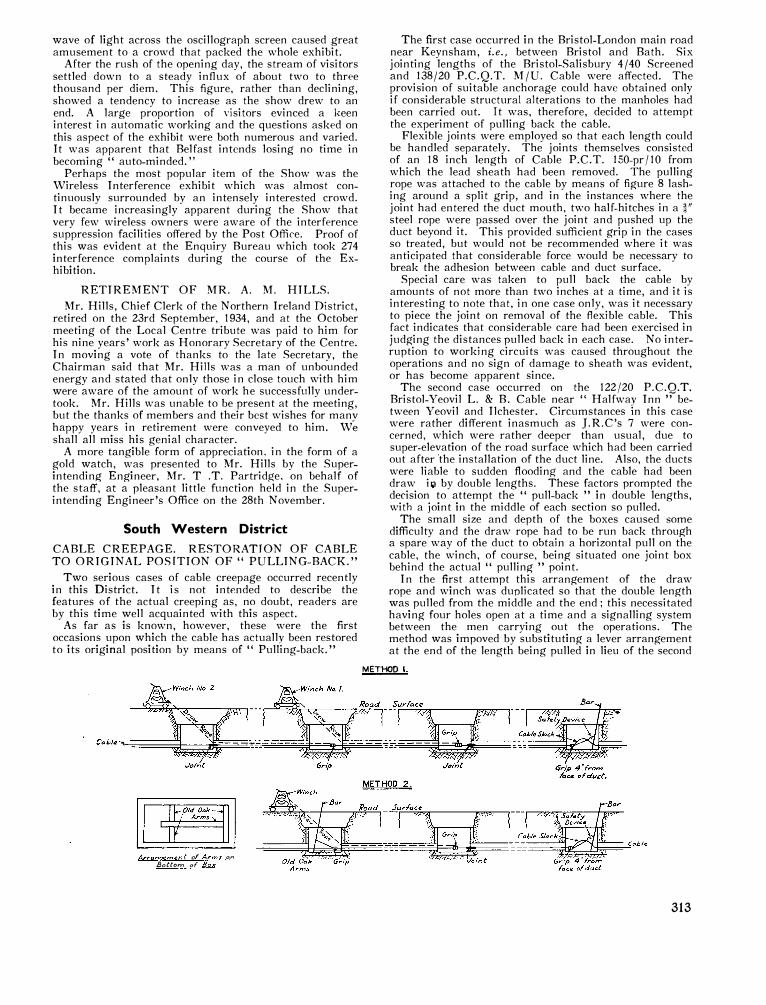
wave of light across the oscillograph screen caused great amusement to a crowd that packed the whole exhibit.
After the rush of the opening day, the stream of visitors settled down to a steady influx of about two to three thousand per diem. This figure, rather than declining, showed a tendency to increase as the show drew to an end. A large proportion of visitors evinced a keen interest in automatic working and the questions asked on this aspect of the exhibit were both numerous and varied. It was apparent that Belfast intends losing no time in becoming " auto-minded."
Perhaps the most popular item of the Show was the Wireless Interference exhibit which was almost continuously surrounded by an intensely interested crowd. It became increasingly apparent during the Show that very few wireless owners were aware of the interference suppression facilities offered by the Post Office. Proof of this was evident at the Enquiry Bureau which took 274 interference complaints during the course of the Exhibition.
RETIREMENT OF MR. A. M. HILLS. Mr. Hills, Chief Clerk of the Northern Ireland District,
retired on the 23rd September, 1934, and at the October meeting of the Local Centre tribute was paid to him for his nine years' work as Honorary Secretary of the Centre. In moving a vote of thanks to the late Secretarv the Chairman said that Mr. Hills was a man of unbo_u
,nded
energy and stated that only those in close touch with him were aware of the amount of work he successfully undertook. Mr. Hills was unable to be present at the meeting, but the thanks of members and their best wishes for manv happy years in retirement were conveyed to him. W� shall all miss his genial character.
A more tangible form of appreciation. in the form of a gold watch, was presented to Mr. Hills by the Superintending Engineer, Mr. T .T. Partridge, on behalf of the staff, at a pleasant little function held in the Superintending Engineer's Office on the 28th November.
South Western District
CABLE CREEPAGE. RESTORATION OF CABLE TO ORIGINAL POSITION OF" PULLING-BACK."
Two serious cases of cable creepage occurred recently in this District. It is not intended to describe the features of the actual creeping as, no doubt, readers are by this time well acquainted with this aspect.
As far as is known, however, these were the first occasions upon which the cable has actuallv been restored to its original position by means of " Pulling-back."
Arran9€rnent of An.,,s on Botto"' of Box
The first case occurred in the Bristol-London main road near Keynsham, i.e., between Bristol and Bath. Six jointing lengths of the Bristol-Salisbury 4/40 Screened and 138/20 P.C.Q.T. M/U. Cable were affected. The provision of suitable anchorage could have obtained only if considerable structural alterations to the manholes had been carried out. It was, therefore, decided to attempt the experiment of pulling back the cable.
Flexible joints were employed so that each length could be handled separately. The joints themselves consisted of an 18 inch length of Cable P.C.T. 150-pr/10 from which the lead sheath had been removed. The pulling rope was attached to the cable by means of figure 8 lashing around a split grip, and in the instances where the joint had entered the duct mouth, two half-hitches in a �" steel rope were passed over the joint and pushed up the duct beyond it. This provided sufficient grip in the cases so treated, but would not be recommended where it was anticipated that considerable force would be necessary to break the adhesion between cable and duct surface.
Special care was taken to pull back the cable by amounts of not more than two inches at a time, and it is interesting to note that, in one case only, was it necessary to piece the joint on removal of the flexible cable. This fact indicates that considerable care had been exercised in judging the distances pulled back in each case. No interruption to working circuits was caused throughout the operations and no sign of damage to sheath was evident, or has become apparent since.
The second case occurred on the 122/20 P.C.Q.T. Bristol-Yeovil L. & B. Cable near " Halfwav Inn " between Yeovil and Ilchester. Circumstances ln this case were rather different inasmuch as J.R.C's 7 were concerned, which were rather deeper than usual, due to super-elevation of the road surface which had been carried out after 'the installation of the duct line. Also, the ducts were liable to sudden flooding and the cable had been draw i� by double lengths. These factors prompted the decision to attempt the " pull-back " in double lengths, with a joint in the middle of each section so pulled.
The small size and depth of the boxes caused some difficulty and the draw rope had to be run back throug-h a spare way of the duct to obtain a horizontal pull on the cable, the winch, of course, being- situated one joint box behind the actual " pulling " point.
In the first attempt this arrangement of the draw rope and winch was duplicated so that the double length was pulled from the middle and the end; this necessitated having four holes open at a time and a signalling system between the men carrying out the operations. The method was impoved by substituting a lever arrangement at the end of the length being pulled in lieu of the second
METHOD I.
313
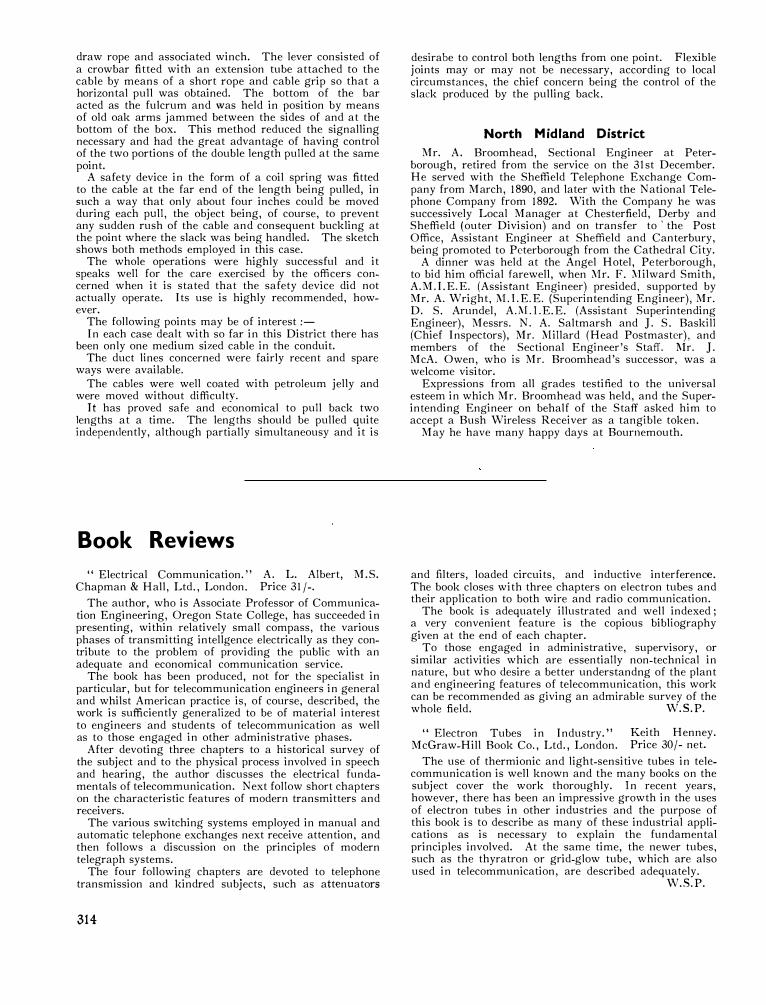
draw rope and associated winch. The lever consisted of a crowbar fitted with an extension tube attached to the cable by means of a short rope and cable grip so that a horizontal pull was obtained. The bottom of the bar acted as the fulcrum and was held in position by means of old oak arms jammed between the sides of and at the bottom of the box. This method reduced the signalling necessary and had the great advantage of having control of the two portions of the double length pulled at the same point.
A safety device in the form of a coil spring was fitted to the cable at the far end of the length being pulled, in such a way that only about four inches could be moved during each pull, the object being, of course, to prevent any sudden rush of the cable and consequent buckling at the point where the slack was being handled. The sketch shows both methods employed in this case.
The whole operations were highly successful and it speaks well for the care exercised by the officers concerned when it is stated that the safety device did not actually operate. Its use is highly recommended, however.
The following points may be of interest:-In each case dealt with so far in this District there has
been only one medium sized cable in the conduit. The duct lines concerned were fairly recent and spare
ways were available. The cables were well coated with petroleum jelly and
were moved without difficultv. It has proved safe and economical to pull back two
lengths at a time. The lengths should be pulled quite independently, although partially simultaneousy and it is
Book Reviews
" Electrical Communication." Chapman & Hall, Ltd., London.
A. L. Albert, Price 31 /-.
M.S.
The author, who is Associate Professor of Communication Engineering, Oregon State College, has succeeded in presenting, within relatively small compass, the various phases of transmitting intellgence electrically as they contribute to the problem of providing the public with an adequate and economical communication service.
The book has been produced, not for the specialist in particular, but for telecommunication engineers in general and whilst American practice is, of course, described, the work is sufficiently generalized to be of material interest to engineers and students of telecommunication as well as to those engaged in other administrative phases.
After devoting three chapters to a historical survey of the subject and to the physical process involved in speech and hearing, the author discusses the electrical fundamentals of telecommunication. Next follow short chapters on the characteristic features of modern transmitters and receivers.
The various switching systems employed in manual and automatic telephone exchanges next receive attention, and then follows a discussion on the principles of modern telegraph systems.
The four following chapters are devoted to telephone transmission and kindred subjects, such as attenuators
314
desirabe to control both lengths from one point. Flexible joints may or may not be necessary, according to local circumstances, the chief concern being the control of the slack produced by the pulling back.
North Midland District
Mr. A. Broomhead, Sectional Engineer at Peterborough, retired from the service on the 3lst December. He served with the Sheffield Telephone Exchange Company from March, 1890, and later with the National Telephone Company from 1892. With the Company he was successively Local Manager at Chesterfield, Derby and Sheffield (outer Division) and on transfer to 'the Post Office, Assistant Engineer at Sheffield and Canterbury, being promoted to Peterborough from the Cathedral City.
A dinner was held at the Angel Hotel, Peterborough, to bid him official farewell, when l\Ir. F. l\Iilward Smith, A.M. I.E.E. (Assistant Engineer) presided, supported by Mr. A. Wright, l\1.1.E.E. (Superintending Engineer), Mr. D. S. Arundel, A. l\1.1. E.E. (Assistant Superintending Engineer), Messrs. N. A. Saltmarsh and J. S. Baskill (Chief Inspectors), Mr. Millard (Head Postmaster), and members of the Sectional Engineer's Staff. l\Ir. J. McA. Owen, who is Mr. Broomhead's successor, was a welcome visitor.
Expressions from all grades testified to the universal esteem in which Mr. Broomhead was held, and the Superintending Engineer on behalf of the Staff asked him to accept a Bush Wireless Receiver as a tangible token.
May he have many happy days at Bournemouth.
and filters, loaded circuits, and inductive interference. The book closes with three chapters on electron tubes and their application to both wire and radio communication.
The book is adequately illustrated and well indexed; a very convenient feature is the copious bibliography given at the end of each chapter.
To those engaged in administrative, supervisory, or similar activities which are essentially non-technical in nature, but who desire a better understandng of the plant and engineering features of telecommunication, this work can be recommended as giving an admirable survey of the whole field. W.S.P.
" Electron Tubes in Industry." McGraw-Hill Book Co., Ltd., London.
Keith Henney. Price 30 /- net.
The use of thermionic and light-sensitive tubes in telecommunication is well known and the many books on the subject cover the work thoroughly. In recent years, however, there has been an impressive growth in the uses of electron tubes in other industries and the purpose of this book is to describe as many of these industrial applications as is necessary to explain the fundamental principles involved. At the same time, the newer tubes, such as the thyratron or grid-glow tube, which are also used in telecommunication, are described adequately.
W.S.P.

Staff Changes PROMOTIONS.
-------
--�ame.
-------1--------
F_r
_o
_m_
. _______ ,
Anson, B. 0. ... ... ... ... Staff Engineer, Equipment Section,
i E.-in-C.0.
Brocklesbey, C.
de Wardt, R. G.
Faulkner, H . ...
Struthers, G. A. Hannaford F. S.
Peck, H. G. S.
Perris, F. R.
Evans, G. T. McDonald, A. G. Palmer, R. W. Hudson, A. Millar, H. T. W. Hill, J. N.
Parker, R. Burrells, W. Colston, A. S .... Lewis, S. G.
Mills, E. G. Parrott, G. Arnold, W. H. Tough, J. D . .. . Haigh, H. L. .. . Lyddall, A. G. Carter, G. W ....
Knights, A. J. L. Twycross, A. E. Allen, F. Woodcock, W. Weakley, H. E. Taylor, H. C .... Bartholomew, C. P .... Brown, E. B .... Bell, T. H. Walker, A. H. Patrick, F. H. Blunt, C. E. ... Barratt, J. W. Stone, M. C . ... Daines, W. J. J. Nolli, L. M . .. . Moller, E. J .. .. Ford, F. V . .. . Robertson, V. Soans, A. T . ... Coster, F. A. J. Townsend, E. E. S. Clevely, S. E ... . Coulson, J. N .. .. Eagle, R. J. A. Perkins, J. J . ... Williams, L. A. Morris, T. G . ... Firmin, E. W. -
Roberts, F. R. Jago, D. V . .. . Elston, F. A . .. . Benzies, A. C. Clarke, T. M. Barton, J. Keast, R. E . ...
I Assistant Superintending Engineer,
I N. West District.
1 Assistant Superintending Engineer, S. West District.
Assistant Superintending Engineer, N. Wales District.
Executive Engineer, Rugby Radio. Executive Engineer, N. Wales District.
Executive Engineer, London District.
.1 Assistant Engineer, S. Eastern District.
Assistant Engineer, E.-in-C.O. Assistant Engineer, Northern District.
Assistant Engineer, E.-in-C.O. Assistant Engineer, N. \Vales District. Assistant Engineer, Scot. East pistrict. Assistant Engineer, London District.
Chief Inspector, Northern District. Chief Inspector, London District.
Chief Inspector, :'-!. Ireland District. Repeater Officer Class II., Northern
District. Inspector, N. Midland District. Inspector, N. Midland District. Inspector, S. Midland District.
Inspector, N. West District. Inspector, N. East District.
Inspector, E.-in-C.O. S.C. & T., Lowestoft.
S.W.I., N. Midland District. S.W.I., N. Midland District. S.W.I., N. Midland District.
S.W. I., London District. S.W. I., London District. S.W. I., London District. S.W.I., London District. S.W.I., London District. S.W.I., London District. S.W.I., London District. S.W.I., London District. S.W.I., London District. S.W. I., London District. S.W.I., S. \Vest District. S.W.I., Eastern District.
S.W.I., Northern District. Draughtsman, Cl. I., E.-in-C.0.
S.W. I., S. West District. S.WI., Scot. East District.
S.W.I., E.-in-C.0. S.W.I., E.-in-C.O. S.W.I., E.-in-C.O. S.W.I., E.-in-C.0. S.W.I., E.-in-C.O. S.W.I., E.-in-C.O. S.W.I., E.-in-C.O. S.W.I., E.-in-C.O. S.W.I., E.-in-C.0.
Chief Officer, H.M.T.S. " Alert." Second Officer, H.M.T.S." Monarch."
Third Officer, H.M.T.S. "Alert." Fourth Officer, H.M.T.S. "Alert."
S.W.I., N. Irelanud District. S.W.I., N. Ireland District. S.W.I., N. Wales District. S.W.I., S. West District.
To.
Assistant Engineer-in-Chief.
Superintending Engineer, N. West District.
Superintending Engineer, S. Eastern District.
Superintending Engineer, N. Wales District.
Assistant Staff Engineer, E.-in-C.O. Assistant Superintending Engineer,
N. Western District. Assistant Superintending Engineer,
N. Wales District. Executive Engineer, S. Eastern
District. Executive Engineer, E.-in-C.O.
Executive Engineer, Northern Dist. Executive Engineer, E.-in-C.O.
Executive Engineer, N. Wales District. Executive Engineer, Scot. East Dist.
Acting Executive Engineer, London District.
Assistant Engineer, Northern Dist. Assistant Engineer, London District. Assistant Engineer, N. Ireland Dist.
Chief Inspector, E.-in-C.O.
Chief Inspector, N. Midland District. Chief Inspector, S. West District.
Chief Inspector, S. Midland Dist. Chief Inspector, S. West District. Chief Inspector, N. East District.
Chief Inspector, E.-in-C.O. Repeater Officer Class II., Eastern
District. Inspector, N. Midland District. Inspector, N. Midland District. Inspector, N. Midland District.
Inspector, London District. 1 Inspector, London District. Inspector, London District. !I Inspector, London District. Inspector, London District. Inspector, London District. Inspector, London District. J Inspector, London District. Inspector, London District. Inspector, London District.
I Inspector, S. West District. Inspector, Eastern District.
Inspector, Northern District. Senior Draughtsman, E.-in-C.0.
Inspector, S. West District. Inspector, Scot. East District.
Inspector, E.-in-C.0. Inspector, E.-in-C.0. Inspector, E.-in-C.O. Inspector, E.-in-C.O. Inspector, E.-in-C.0. Inspector, E.-in-C.O. Inspector, E.-in-C.O. Inspector, E.-in-C.O. Inspector, E.-in-C.O.
Commander, H.M.T.S. "Monarch." Chief Officer, H.M.T.S. "Monarch."
Second Officer, H.M.T.S. "Alert." Third Officer, H.M.T.S. "Alert."
Inspector, N. Ireland District. Inspector, N. Ireland District.
Inspector, N. Wales District. Inspector, S. West District.
Date.
3-12-34
1-2-35
1-1-35
1-1-35
1-1-35
1-2-35
1-1-35
16-10-34
1-1-35
1-12-34
1-1-35
1-2-35
1-1-35
1-1-35
1-12-34
1-1-35
30-8-34
23-7-33
8-9-34
22-9-34
26-8-34
29-7-34
27-11-34
1-6-34
19-5-34
14-4-34
13-6-34
28-7-34
To be fixed later.
1-9-34
7-8-34
4-11-34
5-7-34
9-9-34
5-7-34
5-7-34
5-7-34
5-7-34
5-7-34
5-7-34 5-7-34
28-8-34
3-9-34
6-9-34
6-9-34
15-7-34
12-8-34
9-9-34
1-10-34
315

Name.
Rae, G. ... ... Smart, H. W .... ... Farnworth, w. R. ... Gould, J. W. ... ... Thompson, G. ... Jones, F. ... ... Lieberman, H. J. . . . House, L. F. ... ... Bingham, J. ... . . . Fletcher, w. J. ...
Name.
Hart, A. B. Tissington, H. G. Smith, J. I. Wildgoose, G. H. A .... White, A. E . ... Savory, D. C. Marsden, W. A. Baldry, G. '.'!.
McLeod, J. Trickett, W. . .. Dalston, G. Darvill, H. J. Davidson, T. Ives, B. J.
Cook, A.
Name.
Storey, F. C. Dunning, F. T.
Name.
Morris, A. Warren, A. C. Vickery, W . ... Luxton, W. G. Ramsay, M. W. Harrison, G. B. W .... Pratt, R. 0 . .. . Coates, A. G . .. . Latimer, E. D. Ivory, J. Shrubsall, F. W. Webb, A. W. Dadswell, J. H. Jones, H. E . ...
316
... ...
... ...
. .. ...
... . ..
... ...
... . ..
... ... . .. . ..
I . . . . .. ... . ..
From. To ---- ----- --- --
S.W.1., N. Midland District. Inspector, N. Midland District. S.W.I., s. West District. Inspector, S. West District. S.W.I., N. West District. Inspector, N. West District. S.W.I., N. West District. Inspector, N. West District. S.W.I., N. \Vest District. Inspector, N. West District.
S.W.I., S. Midland District. Inspector, S. Midland District. S.W.I., S. Midland District. Inspector, S. Midland District. S.W.I., S. Midland District. Inspector, S. Midland District. S.W.I., Northern District. Inspector, Northern District.
Draughtsman Class II., E.-in-C.0. Draughtsman Class I., E.-in-C.O.
RETIREMENTS.
Rank.
Assistant Engineer-in-Chief. Executive Engineer. Executive Engineer. Executive Engineer. Executive Engineer. Assistant Engineer.
Chief Inspector. Chief Inspector. Chief Inspector. Chief Inspector.
Inspector. Inspector. Inspector. Inspector.
Rank.
DEATHS.
Chief Inspector. Chief Inspector.
Inspector.
TRANSFERS.
Rank.
Assistant Staff Engineer.
From
E.-in-C.O. E.-in-C.O. Executive Engineer.
Executive Engineer. Assistant Engineer. Assistant Engineer. Assistant Engineer.
S. Eastern District.
Chief Officer. Inspector. Inspector. Inspector. Inspector. Inspector.
Draughtsman Class II. Draughtsman Class II.
E.-in-C.0. E.-in-C.0. E.-in-C.O.
H.M.T.S." Monarch." E.-in-C.0. E.-in-C.0. E.-in-C.O.
London District. E.-in-C.O. E.-in-C.O. , E.-in-C.O.
District.
Scotland East. Northern.
S. Lancashire. S. Lancashire.
N. Eastern. S. West. London.
Northern. N. Eastern.
N. West. S. West. Northern. S. Wales.
District.
Northern. E.-in-C.O.
S. Lancashire.
To
S. Western District. Rugby Radio.
E.-in-C.O. Scot : East District. Scot : East District.
Eastern District. H.M.T.S. "Alert."
London Test Branch. London Test Branch. London Test Branch.
E.-in-C.O. L.E.D. L.E.D.
N. West District.
Date.
26-9-34
25-10-34
20-10-34
5-8-34
20-10-34
12-8-34
23-9-34
2-9-34
11-11-34
16-10-34
Date.
2-12-34
3-11-34
30-11-34
30-11-34
30-9-34
31-10-34
21-9-34
31-10-34
19-11-34
30-11-34
26-10-34
24-10-34
5-11-34
17-10-34
Date.
1-11-34
27-10-34
17-9-34
Date.
1-1-35
1-1-35
16-9-34
1-10-34
1-11-34
9-9-34
3-9-34
17-9-34
17-9-34
17-9-34
17-10-34
2-12-34
2-12-34.
1-10-34

Name.
Coleman, W. L. A.
Seaman, E. C. H.
Smith, D.
Goodchild, R. F.
Turner, C.
Turner, H. A.
Name. -----
Reed, R. E. . . . ...
Nicholls, C. A. L. � · . .
\Vilcockson, H. E. ...
Com bridge, J. H. ...
Maddison, w. H. ...
Blackburn, E. . ..
Millar, D. P. M. ...
Parker, J. D. ... ...
Bray, w. J. ... ...
Pearce, C. A. R. ...
Watson, S. w. ...
Carroll, H. T. ...
Garrett, J. F. ... ...
Name.
Lewis, Major H. E. C. Cowie, G.
Malkin, J. L. .. . Bishop, H. G ... . Lewis, Major H. E. C. Suttle, E. C. Ford, F. C. Glover, G. Smith, G. S. Fraser, W. M. Batey, T. W . ... Boyd, R. Knightbri<lge, H. T .... Topley, W. D. Meredith, C. T. Robertson, N. lnskip, C. R . ... Fraser, \V. M.
... ...
... .. .
... ...
... .. .
... ...
... ...
... ...
. .. .. .
. .. . ..
. .. .. .
. .. ...
... .. .
... . ..
APPOINTMENTS.
From.
Inspector, London District.
Inspector, E.-in-C.0.
Probationary Inspector, Northern Dist.
Inspector, London District.
Draughtsman Class II., N. West District.
Inspector, E.-in-C.O.
To.
Probationary Assistant Engineer, E.-in-C.0.
Probationary Assistant Engineer, N. Midland District.
Probationary Assistant Engineer, Northern District.
Probationary Assistant Engineer,
Probationary Assistant Engineer, E.-in-C.0.
Probationary Assistant Engineer, S. Midland District.
APPOIXTMENTS-continued.
Rank. To. ---- -- --- -- -- ---- -
Inspector, N. Eastern District. Probationary Assistant Engineer, N. Eastern District.
Inspector, S. \Vestern District. Probationary Assistant Engineer, S. Western District.
Inspector, E.-in-C.0. Probationary Assistant Engineer, E.-in-C.O.
Inspector, E.-in-C.O. Probationary Assistant Engineer, s. Eastern District.
Inspector, London District. Probationary Assistant Engineer, London District.
Inspector, E.-in-C.0. Probationary Assistant Engineer, E.-in-C.0.
l Probationary Assistant Engineer,
E.-in-C.O. Probationary Assistant Engineer,
From Open Competition. E.-in-C.O. Probationary Assistant Engineer,
E.-in-C.0. Probationary Assistant Engineer,
E.-in-C.O. U nestablished Draughtsman, Draughtsman Class I I., E.-in-C.0.
E.-in-C.0. U nestablished Draughtsman, Draughtsman, Class II., N. Mid.
N. Midland District. District. U nestablished Draughtsman,
E.-in-C.0. Draughtsman Class II., E.-in-C.O.
CLERICAL GRADES.
PROMOTIONS.
From.
Executive Officer, E.-in-C.O. Clerical Officer, Scot. West Dist.
Staff Officer, E.-in-C.O. Acting Staff Officer, E.-in-C.O. Acting Staff Officer, E.-in-C.O.
Executive Officer, E.-in-C.0. Executive Officer, E.-in-C.O.
Acting Executive Officer, E.-in-C.0. Acting Executive Officer, E.-in-C.O.
Clerical Officer, E.-in-C.0. Clerical Officer, E.-in-C.0. Clerical Officer, E.-in-C. 0. Clerical Officer, E.-in-C.0. Clerical Officer, E.-in-C. 0. Clerical Officer, E.-in-C.0. Clerical Officer, E.-in-C.O. Clerical Officer, E.-in-C.O.
Acting Executive Officer, E.-in-C.0.
To.
Acting Staff Officer, E.-in-C.O. Acting Higher Clerical Officer,
N. Ireland District. P. Clerk, E.-in-C.O.
Staff Officer, E.-in-C.0. Staff Officer, E.-in-C.O.
Acting Staff Officer, E.-in-C.O. Acting Staff Officer, E.-in-C.O.
Executive Officer, E.-in-C.0. Executive Officer, E.-in-C.0.
Acting Executive Officer, E.-in-C.O. Acting Executive Officer, E.-in-C.0. Acting Executive Officer, E.-in-C.0. Acting Executive Officer, E.-in-C. 0. Acting Executive Officer, E.-in-C.0. Acting Executive Officer, E.-in-C.0. Acting Executive Officer, E.-in-C.O. Acting Executive Officer, E.-in-C.O.
Executive Officer, E.-in-C.0.
Date.
1-10-34
1-10-34
1-10-34
To be fixed later.
To be fixed later. 1-10-34
Date.
1-10-34
10-10-34
14-10-34
22-11-34
Date.
31-8-34
14-10-34
1-1-35
1-1-35
24-1-35
1-1-35
24-1-3.5
1-1-35
12-1-35
1-1-35
23-9-34
31-8-34
31-8-34
16-9-34
7-10-34
12-1-35
24-1-35
24-1-35
-
317
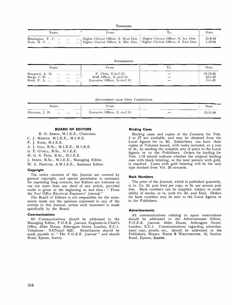
TRANSFERS.
Name. From. Date.
Binnington, T. C. ... ... .. . Higher Clerical Officer, S. West Dist. I To.
Higher Clerical Officer, N. Ire. Dist. 21-8-34 Peak, H. c. ... ... ... . . . Higher Clerical Officer, S. Mid. Dist.
I Higher Clerical Officer, S. East Dist. 1-10-34
RETIREMENTS.
Name. From. To. Date.
Sheppard, A. H. ... . .. .. . P. Clerk, E. in-C.0. - 31-1'2-34 Burge, C. W. ... ... .. . ... Staff Officer, E.-in-C.O. - 23-1-35 Reed, F. L. ... . . . ... .. . Executive Officer, E--in-C.0. - 11-1-35
APPOINTMENT FROM OPEN COMPETITION.
Name. From. Date.
Harrison, J. H. Executive Officer, E.-in-C.O. 12-11-34
BOARD OF EDITORS
B. 0. ANsot1, M. I.E.E. , Chairman. c. J. MERCER, M.I.E.E., M.I. R.E. P. J. Rmo, M.I.E.E. A. J. GrLL, B. Sc., M.I. E.E., M. I.R,E. G. F. O'DELL, B.Sc., '.\J.I.E. E. H. G. S. PECK, B.Sc., M.I. E.E. ]. INNES, B. Sc., M.l.E.E., Managing Editor. W. S. PROCTER, A.M.I.E.E., Assistant Editor.
Copyright
The en tire contents of this Journal are covered by general copyright, and special permission is necessary for reprinting long extracts, but Editors are welcome to use not more than one third of any article, provided credit is given at the beginning or end thus : " From the Post Office Electrical Engineers' Journal."
The Board of Editors is not responsible for the statements made nor the opinions expressed in any of the articles in this Journal, unless such statement is made specifically by the Board.
Communications
All Comn:mnications should be addressed to the Managing Editor, P.O.E.E. Journal, Engineer-in Chief's Office, Alder House, Aldersgate Street, London, E.C.1. Telephone: NATional 6321. Remittances should be made payable to "The P.O.E.E. Journal" and should Road, Epsom, Surrey.
318
Binding Cases
Binding cases and copies of the Contents for Vols. 3 to 27 are available, and may be obtained from the Local Agents for Is. 9d. Subscribers can have their copies of Volumes bound, with index included, at a cost of 3s., by sending the complete sets of parts to the Local Agents or to the Publishers. Orders for binding for Vols. 1-19 should indicate whether the original binding case with black lettering, or the later pattern with gold, is required. Cases with gold lettering will be the only type stocked from Vol. 20 onwards.
Back Numbers
. The price of the Journal, which is published quarterly, 1s ls. (Is. 3d. post free) per copy, or Ss. per annum post free. Back numbers can be supplied, subject to availability of stocks, at Is. each (ls. 3d. post free). Orders for back numbers may be sent to the Local Agents or tu the Publishers.
Advertisements
All communications relating to space reservations should be addressed to the Advertisement Editor, P.O.E.E. Journal, Alder House, Aldersgate Street, London, E.C.1. Communications regarding advertisement copy, proofs, etc., should be addressed to the Publishers, Messrs. BIRCH & WHITTINGTON, 10, Station Road, Epsom, Surrev.

Post Office Electrical Engineers' Journal Volume XXVll-April 1934-March 1935
INDEX
PAGE
A
Akester, A. The Engineer-in-Chief's Training School ... 129 Amos, A. J. Recent Developments in Concrete Kiosk
Construction 204 An Anti-Sidetone Coil for Local Battery Circuits .. . 224 Anson, B. 0. Promotion to Assistant Engineer-in-Chief 301 Arman, L. T., and G. T. Evans. A New High-speed
Multi-channel Carrier Telegraph System 241 Arnold, Capt. A., and J. G. Straw. Sub-audio Telegraph
Working on a Continuously-loaded Submarine Telephone Cable ...
Ashton-in-Makerfield Exchange. A. S. Carr and R. Humphreys ... 290
Autodial, The. W. A. Collett... 161 Automatic Exchanges-Maintenance Replacements. A. L.
Barton 252
B
B.B.C. Studio in Maida Vale, The New 299 Barnes, E. J ., and R. E. Swift. A Tranmission Test Set
for Subscribers' Instruments, Local Lines, and Ex-change Apparatus . . . 207
Bartholomew, S. C. Retirement of ... 71 Barton, A. L. Automatic Exchanges-Maintenance Re-
placements . . . 252 Beard, A. T. J. Omnibus and Conference Circuits 63 Bevis, W. F. The Use of the Teleprinter Distortion and
Margin Tester 9 Birch, S. The London Trunk Centre 187 Birch, S., and C .. H. Hartwell. The British P.O. Inter-
national Exchange . . . 100 Board of Editors ... 80, 160, 240, 318 Book Reviews 67, 76, 156, 178, 232, 236, 314 Brent, W. H. The Manufacture of Porcelain Insulators 39 British Polar Year Expedition, 1932-33 33 Brown, Major H. Promotion to Deputy Engineer-in-Chief 70
c
Carr, A. S., and R. Humphreys. Ashton-in-Makerfield Exchange ...
Carr"ier Telegraph System, A New High-speed Multi-channel. G. T. Evans and L. T. Arman
Carrier Telephony in Underground Cables ... Carrier Telephony on Aerial Lines ... Cave-Browne-Cave, Capt. N. F. Promotion to Super-
intending Engineer ... Central Normal Stock Scheme, An Outline of. A. L.
Barton Chamney, R. M. Telephone Transmission, II. ...
" ''
Chany, F. T., and A. J. Pratt. Collett, W. A. The Autodial Communication Engineering in
III. " IV.
The Mersey Tunnel
East Africa. c. w.
290
241 203 206
147
252 57
139 199
81 161
Millard Communications
13 ... 80, 160, 240, 318
PAGE
D
District Notes ... 73, 148, 237, 309
E
E.H.T. Switchgear with Automatic Change-over Device. L. E. Williams 225
Edwards, J. J. Mechanical Ramming 43 Electrical and Other Services at the P.O. Research
Station. R. S. Phillips . . . 259 England-Australia Air Race. W. M. Osborn 295 Engineer-in-Chief's Training School. A. Akester 129 Engineering Fault Complaint and Repair Service. H.
Mortimer 116 Evans, G. T., and L. T. Arman. A New High-speed
Multi-channel Carrier Telegraph System 241
F
Frequency Characteristics of a W.E. Moving-coil Microphone
G
Gibbon, A. 0. Gilbert, D. P.
The New Liverpool-Glasgow Cable Parcel Conveyors
H
Hart, A. B., Retirement of Hartwell, C. H., and S. Birch. The British P.O. Inter
national Exchange Hedley, J ., Retirement of Hogbin, A. Miscellaneous Facilities at Automatic and
Manual Telephone Exchanges Holmes, M. G., and P. J. Sard. Seven-digit A.C. Key
sending
I
198
279 179
303
100 303
269
166
Innes, J. Promotion to Staff Engineer Institution of P.O. Electrical Engineers
301 143, 233, 306
135 Insulation Test Set giving an Audible Alarm International Exchange, The British P.O. S. Birch and
C. H. Hartwell Introduction of the Standard Telephone Relay, The.
R. W. Palmer
Jenkins, I. H. Josephs, H. J.
Repeaters
J
Promotion to Staff Engineer Note on the Singing Point of Two-wire
Josephs, H. J. Note on the Mutual Impedance between
100
46
302
231
Power and Telephone Lines 61 Junior Section Notes ... 75, 154, 234, 307
319

PAGE
K
Keysender, The Macadie. Lt.-Col. F. Reid 22 Kitchen, H., Retirement of 305
L
Lewis, N. W., and J. E. McGregor. Pneumatic Tube Facilities at the Central Telegraph Office 173
Lipscombe, C. D. Modernizing Teleprinter Diagrams 222 Liverpool-Glasgow Cable, The New. A. 0. Gibbon 279 Local Centre Notes 306 London Trunk Centre, The. S. Birch 187 Loudspeaker Telephone, A 42
M McGregor, J. E., and N. W. Lewis. Pneumatic Tube
Facilities at the Central Telegraph Office 173 McKichan, J. J. Promotion to Superintending Engineer 302 McMillan, D. A Simple Moving-coil Microphone 284 Macadie Keysender, The. Lt.-Col. F. Reid 22 Magnusson, L. E. The Timing of Trunk and Toll Calls 273 Mail Bag Cleaner, A New. W. S. Snell ... 272 Manchester Automatic Area; Engineering Fault Com-
plaint and Repair Service. H. Mortimer 116 Manufacture of Porcelain Insulators, The. W. H.
Brent 39 Mead, F. C. Some Elementary Considerations of the
Significance of Wave Mechanics 36 Measurement of Sidetone 45 Mechanical Ramming. J. J. Edwards 43 Mersey Tunnel, The. A. J. Pratt and F. T. Chany 81 Millard, C. W. Communication Engineering in East
Africa 13 Microphone, A Simple Moving-coil. D. McMillan 284 Miscellaneous Facilities at Automatic and Manual Tele-
phone Exchanges. A. Hogbin . . . 269 Modernizing Teleprinter Diagrams. C. D. Lipscombe.:. 222 Mumford, A. H., and H. Stanesby. A New Type of
Quick Search Radio Receiver 122
N
New Electric Mails Lift. A. E. Penney ... 228 New Type of Quick Search Radio Receiver, A. A. H.
Mumford and H. Stanesby Notes and Comments Notes, District
Local Centre ,, Junior Section
Note on the Graphical Solution mission. T. B. Vinycomb
122 68, 143, 233, 300 73, 148, 237, 309
306 75, 154, 234, 307
of Problems in Trans-
Note on the Mutual Impedance between Power and Telephone Lines. H. J. Josephs
Note on the Singing Point of Two-wire Repeaters. H. J. Josephs
0 Omnibus and Conference Circuits. A. T. J. Beard Oscillator, A Precision Heterodyne. L. E. Ryal!
p Palmer, R. W. The Introduction of the Standard Tele-
136
61
231
63 213
phone Relay 46 Parcel Conveyors. D. R. Gilbert ... 179 Partridge, T. T. Promotion to Superintending Engineer 145 Penney, A. E. A New Electric Mails Lift... 228 Phillips, R. S. Electrical and Other Services at the P.O.
Research Station 259 Powell, W. H. Promotion to Staff Engineer 147 Pneumatic Tube Facilities at the Central Telegraph Office.
J. E. McGregor and N. W. Lewis 173 Pratt, A. J., and F. T. Chany. The Mersey Tunnel 81 Prpcision Heterodyne Oscillator. L. E. Ryall 213 Proposed Design for Speaking Clock... 142
320
PAGE
R Radio Receiver, A New Type of Quick Search. A. H.
Mumford and H. Stanesby 122 Reading, J. Routed Schematic Diagrams . . . 50 Recent Developments in Concrete Kiosk Construction.
A. J. Amos ... 204 Reconditioning Telegraph Circuits for Audio and Carrier
Working. E. J. Woods ... 133 Reid, Lt.-Col. F. The l\1acadie Keysender... 22 Relay, The Standard Telephone, Introduction of. R. W.
P�mcr � Richardson, E. G. Some Acoustical Aspects of Telephony 52 Routed Schematic Diagrams. J. Reading ... 50 Ryall, L. E. A Precision Heterodyne Oscillator ... 213
s
Seven-digit A.C. Keysending. M. G. Holmes and P. J. Sard
Simple Moving-coil Microphone, A. D. McMillan Singing Point of Two-wire Repeaters, Note on. H. J.
Josephs Smith, H. A. Promotion to Superintending Engineer Snell, W. S. A New Mail Bag Cleaner Some Acoustical Aspects of Telephony. E. G. Richardson Some Elementary Considerations of the Significance of
166 284
231 146 272
52
Wave Mechanics. F. C. Mead ... Staff Changes Stanesby, H., and A. H. Mumford.
36 . .. 77, 158, 238, 315
A New Type of Quick Search Radio Receiver ...
Stratton, J. Transmission of Pictures by means of Mobile Transmission Sets
Straw, J. G., and Capt. A. Arnold. Sub-audio Telephone \Vorking on a Continuously-loaded Submarine Cable
Sub-audio Telegraph Working on a Continuously-loaded Submarine Telephone Cable. J. G. Straw and Capt. A. Arnold
Swift, R. E., and E. J. Barnes. A Transmission Test Set for Subscribers' Instruments, Local Lines, and Exchange Apparatus ...
T Telegraph and Telephone Plant in the U .K . ...
122
112
207
35, 121, Telephone Transmission-II. R. M. Chamney ...
172, 268
II I. IV.
Telephone \Veek"
at the London Trunk,,
Exchange Teleprinter Diagrams, Modernizing. C. D. Lipscombe ... Teleprinter Distortion and Margin Tester, Use of. W. F.
Bevis Teleprinter Voice Frequency Broadcasting Scheme Timing of Trunk and Toll Calls, The. L. E. Magnusson Training School, The Engineer-in-Chief's. A. Akester ... Transmission of Pictures by Mobile Transmission Sets.
J. Stratton ... Transmission Test Set for Subscribers' Instruments, Local
Lines, and Exchange Apparatus. E. J. Barnes and R. E. Swift ...
u
Use of the Teleprinter Distortion and Margin Tester. W. F. Bevis ...
y
Vinycombe, T. B. Note on the Graphical Solution of
57 139 199 297 222
9 132 273 129
112
207
9
Problems in Transmission 136 Voice Frequency Valve Receiver 138
w
Wave Mechanics, Some Elementary Considerations of the Significance of. F. C. Mead 36
Weaver, R. A. Retirement of 304 Whillis, C. Retirement of 145 Williams, L. E. E. H. T. Switchgear with Automatic
Change-over Device 225 Woods, E. J. Reconditioning Telegraph Circuits for
Audio and Carrier Working 133 Wright, A. Promotion to Superintending Engineer 70