the possibility of monitoring forces during turning
TRANSCRIPT

The Possibility of Monitoring Forces during Turning Process of Shafts
Made of AW-7020 Aluminium Alloy for Variable Treatment Conditions
WOJCIECH LABUDA
Marine Maintenance Department Faculty of Marine Engineering Gdynia Maritime University
81-225 Gdynia, 81-87 Morska St. POLAND
[email protected]; http://www.wm.umg.edu.pl
Abstract: - The article presents the research results referring to the analysis of the influence of cutting parameters on value of cutting forces during turning pins of shaft. For the monitoring of forces during lathing process used Kistler dynamometer. The dynamometer is used for dynamic and quasistatic measurements of the 3 orthogonal components of any forces acting on the cover plate (Fx - radial force, Fy - feed force and Fz - cutting force). The turning process was carried out on a universal CU500MRD/1000 centre lathe. The research was performed on a shaft made of 7020 aluminium alloy. Chemical composition of aluminium alloy was measured by Solaris-ccd plus optical spectrometer. The finishing turning process was carried out by cutting tool with CCGT09T302-DL removable insert by Duracarb. During turning the following machining parameters were used: cutting speed, feed and depth of cut. The goal of the paper was to define the influence of treatment conditions on values of forces during turning process, and thus monitoring the wear of the cutting insert. Key-Words: - 7020 aluminium alloy, turning process, cutting forces Received: January 9, 2020, Revised: July 1, 2020. Accepted: July 14, 2020. Published: August 6, 2020.
1 Introduction Turning operations become important subject in industries and also in research and development. These are mostly used in automobile, gear, die and bearing industries [1]. For the basic method of the surface layer forming of shaft pins is turning machining. Processes of producing machine parts on conventional machine accuracy is usually considered as a function of the characteristics of all the components of machine tool, fixture, object and tool. There are: accuracy performance and the accuracy of static and dynamic determining and cutting parameters, which are associated with strength, temperature and wear of the cutting edge. In the various research centers, researchers deal with the mentioned issues. The influence of variable treatment conditions on the values of cutting force and temperature during turning of 304L stainless steel is presented in my previous work [2]. While Rao et al., conducted research on tool wear monitoring during hard turning operations of Inconel 718 with varying HRC (51, 53, and 55) with the use of acoustic emission [3]. Similarly, Bhuiyan et al., in their research, used the phenomenon of acoustic emission and additionally vibration signature to monitor tool wear, chip formation and analyze the surface roughness of the workpiece under various cutting conditions [4]. In the article
by Lalwani et al., the influence of cutting parameters on the cutting forces and surface roughness parameters in hard turning of MDN250 steel was determined [5]. However Balsamo et al. have attempted to identify a catastrophic tool failure (CTF) in turning processes using a multi-sensor monitoring system consisting of a force sensor and an acoustic emission sensor [6]. Therefore, stock removal of high efficiency should be performed in a controlled manner which ensures the correct shape and size of the chip. In order to achieve low cutting force, reduced wear of tool, chip breakability and good quality of surface, the proper selection machining process parameters and tools are important factors to be considered during machining different materials [7].
Many scientific centres deal with issues related to the turning surface of the difficult-to-machine. Schmidt et al., used several interesting materials in their research, such as: M42 tool steel, tungsten tantalum alloy, aluminium 6061, and Nitronic 33 stainless steel [8]. Zhou et al. conducted research in the field of hard turning of samples made of, among others, 100Cr6 steel [9]. While Yaman et al., analyze the machining process to determine the effective machining parameters namely of SAE 1030 forged steel [10]. Researchers Teti et al., reviewed the sensors used to monitor the machining
WSEAS TRANSACTIONS on SYSTEMS and CONTROL DOI: 10.37394/23203.2020.15.32 Wojciech Labuda
E-ISSN: 2224-2856 311 Volume 15, 2020
process in its various aspects. They presented future challenges and trends in monitoring machining operations with sensors and gave examples of their applications in industrial processes [11].
Aluminium alloys (except for some grades) are well machinable, however their machinability is different from other metals which requires different machining conditions. This is due to the properties of aluminium alloys such as: high coefficient of linear expansion (for steel this factor is twice lower), high thermal conductivity [12]. Aluminium alloys belong to the group of materials that cause difficulties in machining. Many research refers to the various types of aluminium alloys, that are subjected to machining in variable treatment conditions. Nataraj et al. researched the influence of turning process parameters on the machinability of hybrid metal matrix composite comprising alumina (Al2O3) and molybdenum disulphide (MoS2) particulates dispersed on aluminium casting alloy LM6 in turning process [7]. While Palaniappan et al., used the aluminium alloy 6082 to optimize the parameters in the CNC turning process [13]. Other researchers (Karthikeyan et al.) who carried out such research used Aluminium Alloy 6063 [14]. Another example of research using aluminium alloys is the article of researchers Otieno et al., who determined investigates the machinability of rapidly-solidified aluminium [15].
Many researchers undertook tests based on simulations of the turning process using various software tools. The accuracy of any software tool can only be guaranteed by providing accurate material properties in terms of material constants. Therefore, it is important to perform experimental tests to learn the required material constants and to learn about the impact of machining conditions on the cutting process. Mali et al., in the article presents the results of simulated cutting forces obtained from a finite element based Deform-3D software in dry turning of Aluminium 7075 alloy with the experimental results [1]. While Teimouri et al., presents the experimental investigation and analysis of the machining parameters while turning aluminium 7075 alloy with the development of an empirical model [16]. Pan et al., presented FEM simulations of the damaged area with material separation at the nose radius of tool [17]. In an article by Saravanan et al., 6082 aluminium alloy blended with a boron carbide reinforced material by mechanical mixing was examined. Researchers performed SEM analysis and the castings are machined on CNC machines. Machinability studies are compared with mono alloy and composite materials [18].
Shafts made of aluminium alloy AW-7020 were used for the research. In the 90s, Al-Zn-Mg (7xxx series) alloys attracted great interest. They exhibit higher strength properties than the mechanical properties of Al-Mg alloys. The disadvantage of the Al-Zn-Mg alloys is that they are prone to stress and layer corrosion. Many years of research have shown that the resistance of these alloys to stress corrosion is influenced among other things by heat processing, chemical composition and welding technology (welding method, type of fillers, type of joint) [19]. Al-Zn-Mg alloys also show good machinability and dimensional stability. Limiting their use is associated with low resistance to high temperatures and corrosion, in particular stress. They are manufactured in the form of sheets, rods, forgings and shape. Dural zinc are widely used in the manufacture of various machine parts, motor vehicles, railway rolling stock, as well as aircraft structural components [12].
The determination of cutting forces during the turning processes enables to evaluate the machinability of a material. The magnitude of cutting forces are related to the amount of heat in the cutting area, tool wear, quality of surface and accuracy of the workpiece. It is assumed that aluminium alloys have better machinability than steel, so the required force for machining aluminium is about 30% of that required for machining steel [20]. During aluminium alloy turning process, proper chip evacuation may be a problem. The basic technological problems occurring in the machining process of aluminium alloys include: removal of chips from the cutting zone, formation of adherence to the cutting tool, shaping the surface unevenness, wear of cutting tool, temperature and forces. In addition, obtaining the good surface quality of the processed shaft may be unsatisfactory, due to the surface of the machined shaft being drawn by a snarled chip, that cannot be fully controlled. Due to the large possibilities of tool configuration, treatment conditions during turning process and other outside factors interfering with machining, it is important to experimentally measure the cutting forces to determine the most favourable cutting conditions. The article presents the results of research on the impact of variable turning parameters on force values and monitoring of cutting process of AW7020 aluminium alloy. 2 The research methodology The turning process is a complex issue that is influenced by many factors. In production, the appropriate quality of the manufactured part should
WSEAS TRANSACTIONS on SYSTEMS and CONTROL DOI: 10.37394/23203.2020.15.32 Wojciech Labuda
E-ISSN: 2224-2856 312 Volume 15, 2020

be ensured, while ensuring adequate production efficiency. The variety of material type means, that there are many options for choosing cutting tools. Due to the metallurgical and mechanical properties of the materials, they determine the susceptibility of the processed material to processing. In addition, the alloy additions of individual materials can affect the conditions during the cutting process. Increasing the percentage of some of their elements may result in faster wear of the cutting inserts. Therefore, it is important to select the right cutting insert (insert material grade, geometry, etc.), cutting parameters, cooling method, machine tool type, etc. In most cases, the machinability of a given material is assessed through practical tests, the results of which are compared with the results for another type of material obtained under very similar conditions. During the tests are taken into account other factors, such as microstructure, the tendency to adhesion, stability, noise, tool life, chip formation, etc. As a part of our own research, the AW7020 aluminium alloy is used due to its properties and the possibility of its application in the shipbuilding industry.
The research was performed on a shaft made of AW-7020 aluminium alloy (Fig. 1). The diameter of the shaft used in the tests was 55 mm. The process of turning was carried out on a lathe CU500MRD/1000 type (see Fig. 2) by a cutting tool with removable insert CCGT09T302-DL type by Duracarb.
Fig. 1. The view of shaft used in research.
Fig. 2. Lathe type: CU500MRD/1000.
Basic information about the cutting insert: C – rhombic insert shape with point angle 80°; C – insert clearance angle 7°; G – tolerance (nose height ±0.025 mm; thickness ± 0.13 mm; inscribed circle ±0.025 mm); T – insert type (single sided CB Screw hole); 09 - insert size = cutting edge length – 9.525 mm; T3 - insert thickness – 3.97 mm; 02 –nose radius 0.2 mm; DL – chibreaker.
There are different methods that are used to monitor the cutting process, which are presented in the article Teti et al., “Advanced Monitoring of Machining Operations, CIRP Annals-Manufacturing Technology” [11]. Kistler dynamometer is a high-quality measuring device, which is used to measure forces in machining. It is used in laboratory research as well as in industry. The tests are of a basic character and the dynamometer used for monitoring the turning process allows the registration of important details related to the variable cutting conditions. The article presents the most important information about the dynamometer used in the tests.
Measuring chain consists of piezoelectric dynamometer (9119AA2 type), connecting cable and multichannel charge amplifier (5070 type) as well as a data acquisition and analysis system (DynoWere). The dynamometer is used for dynamic and quasistatic measurements of the 3 orthogonal components of any forces acting on the cover plate (Fx - radial force, Fy - feed force and Fz - cutting force) (Fig. 3). The range of measured forces is ± 4 kN. The dynamometer measures the active force, irrespective of its application point.
Fig. 3. Dynamometr (top view).
Dynamometer allowed measuring the cutting
forces during lathing process, both on conventional or CNC lathe machines. An example of the use of a
WSEAS TRANSACTIONS on SYSTEMS and CONTROL DOI: 10.37394/23203.2020.15.32 Wojciech Labuda
E-ISSN: 2224-2856 313 Volume 15, 2020

Kistler dynamometer on a conventional lathe is presented in the article by Bensouilah et al., The research part of which was carried out on a machine tool TOS TRENCIN; model SN40C [21]. While Sadilek et al., in research cutting machine was used: DMG MORI NLX 2500MC/700 with control system Mitsubishi M730BM [22]. Researchers Rahman et al., performed the experimental part of the research work on the high precision four-axis CNC machine (Toshiba ULG 100C) used for micro turning experiments [23]. The view of equipment used in research is presented in Fig. 4. The tool was mounted into Kistler dynamometer.
Fig. 4.The view of equipment used in research: 1 - grip
for dynamometer, 2 – dynamometer, 3 –tool with removable insert.
During turning the following machining
parameters were used: cutting speed (Vc), feed (f) and depth of cut (ap). The cutting parameters used in the finish lathing process are presented in Table 1.
On the basis of the information specified by the manufacturer of the insert the selected cutting parameters were chosen for their respective fields of application. For particular attempts to set two fixed cutting parameters, and six variable parameter values for the chosen preserving as far as possible equal section range. The selection of the feed value was also conditioned by the lathe setting capabilities. The turning machine is equipped with a specially made tool post, which ensures the appropriate stiffness of the measuring system.
The turning process was carried out without the use of a coolant liquid due to the ecological and economic aspects. The lathe used in the tests has a coolant intended mainly for turning process of steel. Aluminium requires a special type of cooling lubricant. Additionally, shaft pins are machined for a relatively short time with cutting parameters dedicated to finishing turning.
Table 1. Technological parameters.
Shaft
number
cutting parameters
Vc [m/mm]
f [mm/rev]
ap [mm]
I
138.2
0.078 1.0
172.7 207.2 241.8 276.3 310.9
II 276
0.039
1.0
0.078 0.131 0.168 0.196 0.236
III 276 0.078
0.5 1.0 1.5 2.0 2.5 3.0
Analysis of the chemical composition of the
sample material was carried out on a Solaris-ccd plus spectrometer (Fig. 5 ). It is an optical emission ––spectrometer with spark excitation by GNR. It performs the analysis of solid samples and metal alloys of different matrices. Percentage contents of selected elements in steel was presented for sample after three spark test (Fig. 6).
Fig. 5. Solaris-ccd plus optical spectrometer.
WSEAS TRANSACTIONS on SYSTEMS and CONTROL DOI: 10.37394/23203.2020.15.32 Wojciech Labuda
E-ISSN: 2224-2856 314 Volume 15, 2020
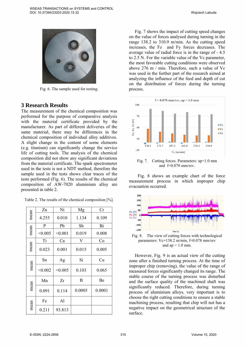
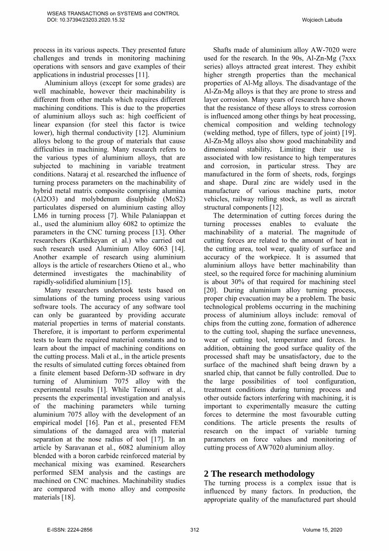
Fig. 6. The sample used for testing.
3 Research Results The measurement of the chemical composition was performed for the purpose of comparative analysis with the material certificate provided by the manufacturer. As part of different deliveries of the same material, there may be differences in the chemical composition of individual alloy additives. A slight change in the content of some elements (e.g. titanium) can significantly change the service life of cutting tools. The analysis of the chemical composition did not show any significant deviations from the material certificate. The spark spectrometer used in the tests is not a NDT method, therefore the sample used in the tests shows clear traces of the tests performed (Fig. 6). The results of the chemical composition of AW-7020 aluminium alloy are presented in table 2.
Table 2. The results of the chemical composition [%].
mea
n Zn Ni Mg Cr
4.255 0.010 1.134 0.109
mea
n P Pb Sb Bi <0.005 <0.001 0.019 0.008
mea
n Ti Ca V Co
0.023 0.001 0.015 0.005
mea
n Sn Ag Si Cu
<0.002 <0.005 0.103 0.065
mea
n Mn Zr B Be
0.091 0.114 0.0005 0.0001
mea
n Fe Al
0.211 93.813
Fig. 7 shows the impact of cutting speed changes on the value of forces analysed during turning in the range 138.2 to 310.9 m/min. As the cutting speed increases, the Fz and Fy forces decreases. The average value of radial force is in the range of - 4.5 to 2.5 N. For the variable value of the Vc parameter, the most favorable cutting conditions were observed above 276 m / min. Therefore, such a value of Vc was used in the further part of the research aimed at analyzing the influence of the feed and depth of cut on the distribution of forces during the turning process.
Fig. 7. Cutting forces. Parameters: ap=1.0 mm
and f=0.078 mm/rev. Fig. 8 shows an example chart of the force
measurement process in which improper chip evacuation occurred.
Fig. 8. The view of cutting forces with technological
parameters: Vc=138.2 m/min, f=0.078 mm/rev and ap = 1.0 mm.
However, Fig. 9 is an actual view of the cutting
zone after a finished turning process. At the time of improper chip (removing), the value of the range of measured forces significantly changed its range. The stable course of the turning process was disturbed and the surface quality of the machined shaft was significantly reduced. Therefore, during turning process of aluminium alloys, very important is to choose the right cutting conditions to ensure a stable machining process, resulting that chip will not has a negative impact on the geometrical structure of the surface.
WSEAS TRANSACTIONS on SYSTEMS and CONTROL DOI: 10.37394/23203.2020.15.32 Wojciech Labuda
E-ISSN: 2224-2856 315 Volume 15, 2020
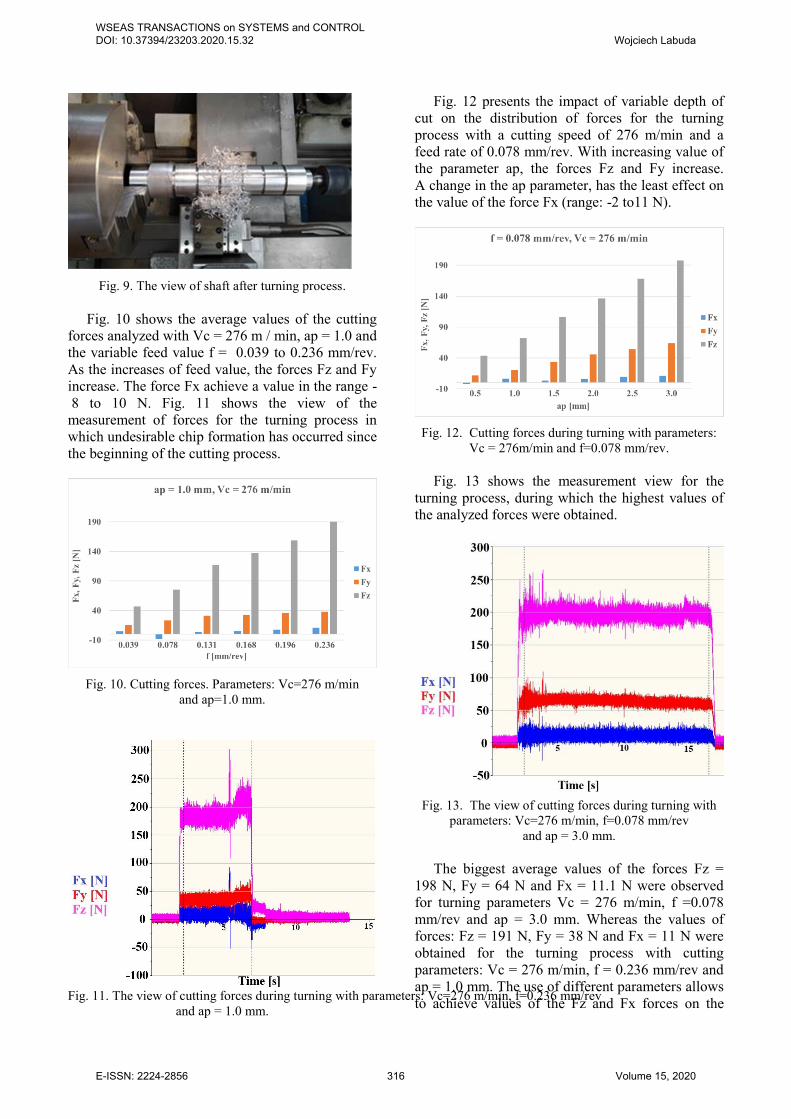
Fig. 9. The view of shaft after turning process.
Fig. 10 shows the average values of the cutting
forces analyzed with Vc = 276 m / min, ap = 1.0 and the variable feed value f = 0.039 to 0.236 mm/rev. As the increases of feed value, the forces Fz and Fy increase. The force Fx achieve a value in the range - 8 to 10 N. Fig. 11 shows the view of the measurement of forces for the turning process in which undesirable chip formation has occurred since the beginning of the cutting process.
Fig. 10. Cutting forces. Parameters: Vc=276 m/min
and ap=1.0 mm.
Fig. 11. The view of cutting forces during turning with parameters: Vc=276 m/min, f=0.236 mm/rev and ap = 1.0 mm.
Fig. 12 presents the impact of variable depth of cut on the distribution of forces for the turning process with a cutting speed of 276 m/min and a feed rate of 0.078 mm/rev. With increasing value of the parameter ap, the forces Fz and Fy increase. A change in the ap parameter, has the least effect on the value of the force Fx (range: -2 to11 N).
Fig. 12. Cutting forces during turning with parameters:
Vc = 276m/min and f=0.078 mm/rev.
Fig. 13 shows the measurement view for the turning process, during which the highest values of the analyzed forces were obtained.
Fig. 13. The view of cutting forces during turning with
parameters: Vc=276 m/min, f=0.078 mm/rev and ap = 3.0 mm.
The biggest average values of the forces Fz =
198 N, Fy = 64 N and Fx = 11.1 N were observed for turning parameters Vc = 276 m/min, f =0.078 mm/rev and ap = 3.0 mm. Whereas the values of forces: Fz = 191 N, Fy = 38 N and Fx = 11 N were obtained for the turning process with cutting parameters: Vc = 276 m/min, f = 0.236 mm/rev and ap = 1.0 mm. The use of different parameters allows to achieve values of the Fz and Fx forces on the
WSEAS TRANSACTIONS on SYSTEMS and CONTROL DOI: 10.37394/23203.2020.15.32 Wojciech Labuda
E-ISSN: 2224-2856 316 Volume 15, 2020
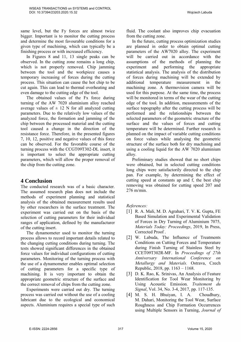
same level, but the Fy forces are almost twice bigger. Important is to monitor the cutting process and determine the most favourable conditions for a given type of machining, which can typically be a finishing process or with increased efficiency.
In Figures 8 and 11, 13 single peaks can be observed. In the cutting zone remains a long chip, which is not properly removed. Chip jamming between the tool and the workpiece causes a temporary increasing of forces during the cutting process. This situation can cause the hot chip to be cut again. This can lead to thermal overheating and even damage to the cutting edge of the tool.
The obtained values of the Fx force during turning of the AW 7020 aluminium alloy reached average values of ± 12 N for all analyzed cutting parameters. Due to the relatively low values of the analyzed force, the formation and jamming of the chip between the processed material and the cutting tool caused a change in the direction of the resistance force. Therefore, in the presented figures 7, 10, 12, positive and negative values of this force can be observed. For the favorable course of the turning process with the CCGT09T302-DL insert, it is important to select the appropriate cutting parameters, which will allow the proper removal of the chip from the cutting zone. 4 Conclusion The conducted research was of a basic character. The assumed research plan does not include the methods of experiment planning and statistical analysis of the obtained measurement results used by other researchers in the surface treatment. The experiment was carried out on the basis of the selection of cutting parameters for their individual ranges of application, defined by the manufacturer of the cutting insert.
The dynamometer used to monitor the turning process allows to record important details related to the changing cutting conditions during turning. The tests showed significant differences in the obtained force values for individual configurations of cutting parameters. Monitoring of the turning process with the use of a dynamometer enables optimal selection of cutting parameters for a specific type of machining. It is very important to obtain the appropriate geometric structure of the surface and the correct removal of chips from the cutting zone.
Experiments were carried out dry. The turning process was carried out without the use of a cooling lubricant due to the ecological and economical aspects. Aluminium requires a special type of such
fluid. The coolant also improves chip evacuation from the cutting zone.
In the future, cutting process optimization studies are planned in order to obtain optimal cutting parameters of the AW7020 alloy. The experiment will be carried out in accordance with the assumptions of the methods of planning the experiment and performing the appropriate statistical analysis. The analysis of the distribution of forces during machining will be extended by additional temperature measurement in the machining zone. A thermovision camera will be used for this purpose. At the same time, the process will be monitored in terms of the wear of the cutting edge of the tool. In addition, measurements of the surface topography after the cutting process will be performed and the relationships between the selected parameters of the geometric structure of the surface and the values of forces and cutting temperature will be determined. Further research is planned on the impact of variable cutting conditions on force values while analysing the geometric structure of the surface both for dry machining and using a cooling liquid for the AW 7020 aluminium alloy.
Preliminary studies showed that no short chips were obtained, but in selected cutting conditions long chips were satisfactorily directed to the chip pan. For example, by determining the effect of cutting speed at constants ap and f, the best chip removing was obtained for cutting speed 207 and 276 m/min. References: [1] R. A. Mali, M. D. Agrahari, T. V. K. Gupta, FE
Based Simulation and Experimental Validation of Forces in Dry Turning of Aluminium 7075, Materials Today: Proceedings, 2019, In Press, Corrected Proof .
[2] W. Labuda, The Influence of Treatments Conditions on Cutting Forces and Temperature during Finish Turning of Stainless Steel by CCET09T302R-MF. In Proceedings of 27th Anniversary International Conference on Metallurgy and Materials. Ostrava, Czech Republic, 2018, pp. 1163 – 1168.
[3] D. K. Rao, K. Srinivas, An Analysis of Feature Identification for Tool Wear Monitoring by Using Acoustic Emission. Traitement du Signal, Vol. 34, No. 3-4, 2017, pp. 117-135.
[4] M. S. H. Bhuiyan, I. A. Choudhury, M. Dahari, Monitoring the Tool Wear, Surface Roughness and Chip Formation Occurrences using Multiple Sensors in Turning, Journal of
WSEAS TRANSACTIONS on SYSTEMS and CONTROL DOI: 10.37394/23203.2020.15.32 Wojciech Labuda
E-ISSN: 2224-2856 317 Volume 15, 2020

Manufacturing Systems, Vol. 33, No. 4, 2014, pp. 476-487.
[5] D. I. Lalwani, N. K. Mehta, P. K. Jain, Experimental Investigations of Cutting Parameters Influence on Cutting Forces and Surface Roughness in Finish Hard Turning of MDN250 Steel. Journal of Materials Processing Technology, Vol. 206, No. 1–3, 2008, pp. 167-179.
[6] V. Balsamo, A. Caggiano, K. Jemielniak, J. Kossakowska, M. Nejman, R. Teti, Multi Sensor Signal Processing for Catastrophic Tool Failure Detection in Turning. In Research and Innovation in Manufacturing: Key enabling technologies for the factories of the future - Proceedings of the 48th CIRP Conference On Manufacturing Systems, Vol. 41, Ischia, Italy, 2016, pp. 939-944.
[7] M. Nataraj, K. Balasubramanian, D. Palanisamy, Influence of Process Parameters on CNC Turning of Aluminium Hybrid Metal Matrix Composites, Materials Today: Proceedings, Vol. 5, Part 2, 2018, pp.14499-14506.
[8] P. L. Schmidt, J. K. Nelson, R . G. Handy, J. S. Morrell, M .J . Jackson, T . M. Rees, Noncontact Measurements of Acoustic Emissions from the Single-Point Turning Process. International Journal of Advanced Manufacturing Technology, Vol. 93, No. 9-12, 2017, pp. 3907-3920.
[9] J. M. Zhou, M. Andersson, J. E Ståhl,. Identification of Cutting Errors in Precision Hard Turning Process. Journal of Materials Processing Technology, Vol. 153–154, 2004, pp. 746-750.
[10] K. Yaman, M. Basaltin, Investigations on the Cutting Parameters and the Tool Wear of SAE 1030 Forged Steel Material by Acoustic Emission in Turning Operation. Journal of the Faculty of Engineering and Architecture of Gazi University, Vol. 32, No. 4, 2017, pp. 1077-1088.
[11] R. Teti, K. Jemielniak, G. O'Donnell, D. Dornfeld, Advanced Monitoring of Machining Operations, CIRP Annals-Manufacturing Technology, Vol. 59, No. 2, 2010, pp. 717-739.
[12] J. Kuczmaszewski, K. Zaleski, Machining of Aluminium and Magnesium Alloys, Monographs, Lublin University of Technology, Poland, 2015.
[13] S. P. Palaniappan, K. Muthukumar, R. V. Sabariraj, S. Dinesh Kumar, T. Sathish, CNC
Turning Process Parameters Optimization on Aluminium 6082 Alloy by using Taguchi and ANOVA, Materials Today: Proceedings, Vol. 21, Part 1, 2020, pp 1013-102.
[14] S. C. Karthikeyan, B. Dhamotharan, V. Gokul Kumar, Optimization of CNC Turning Parameters on Aluminum Alloy 6063 using Taguchi Robust Design, Materials Today: Proceedings, 2018, pp. 8290–8298.
[15] T. Otieno, K. Abou-El-Hossein, Cutting Forces and Acoustic Emission in the Diamond Turning of Rapidly-Solidified Aluminium, The Journal of the British Institute of Non-Destructive Testing, Vol. 60, No. 1, 2018, pp. 11-18.
[16] R. Teimouri, S. Amini, N. Mohagheghian, Experimental Study and Empirical Analysis on Effect of Ultrasonic Vibration During Rotary Turning of Aluminum 7075 Aerospace Alloy, Journal of Manufacturing Processes, Vol. 26, 2017, pp. 1–12.
[17] H. Pan, J. Liua, Y. Choib, C. Xuc, Y. Baia, T. Atkins, Zones of Material Separation in Simulations of Cutting, International Journal of Mechanical Sciences, Vol. 115–116, 2016, pp. 262-279.
[18] K. K. Saravanan, S. Mahendran, Aluminium 6082-Boron Carbide Composite Materials Preparation and Investigate Mechanical-Electrical Properties with CNC Turning, Materials Today: Proceedings, Volume 21, Part 1, 2020, pp. 93-97.
[19] K. Dudzik, W. Jurczak, Influence of Friction Stir Welding (FSW) on Mechanical and Corrosion Properties of AW-7020M and AW-7020 Aloys, Polish Maritime Research, Vol. 23, No. 3, 2016, pp. 86-90.
[20] B. de Agustina, C. Bernal, A. M. Camacho, E.M. Rubio, Experimental Analysis of the Cutting Forces Obtained in Dry Turning Processes of UNS A97075 Aluminium Alloys, Procedia Engineering, Vol 63, 2013, pp. 694-699.
[21] H. Bensouilah, H. Aouici, I. Meddour, M. A. Yallese, T. Mabrouki, F. Girardin, Performance of Coated and Uncoated Mixed Ceramic Tools in Hard Turning Process. Measurement, Vol. 82, 2016, pp. 1–18.
[22] M. Sadilek, J. Dubský, Z. Sadílková, Z. Poruba, Cutting Forces During Turning with Variable Depth of Cut, Perspectives in Science, Vol. 7, 2016, pp. 357-363.
[23] M. A. Rahman, M. Rahman, M. Mia, M. K. Gupta, B. Sen, A. Ahmed, Investigation
WSEAS TRANSACTIONS on SYSTEMS and CONTROL DOI: 10.37394/23203.2020.15.32 Wojciech Labuda
E-ISSN: 2224-2856 318 Volume 15, 2020

of the Specific Cutting Energy and its Effect in Shearing Dominant Precision Micro Cutting. Journal of Materials Processing Technology, Vol. 283, 2020, art. No. 116688.
Creative Commons Attribution License 4.0 (Attribution 4.0 International, CC BY 4.0)
This article is published under the terms of the Creative Commons Attribution License 4.0 https://creativecommons.org/licenses/by/4.0/deed.en_US
WSEAS TRANSACTIONS on SYSTEMS and CONTROL DOI: 10.37394/23203.2020.15.32 Wojciech Labuda
E-ISSN: 2224-2856 319 Volume 15, 2020