the output lp/bp filters for transceivers genesis g ...yu1lm.qrpradio.com/output hf-6m lp-bp filters...
TRANSCRIPT

The Output LP/BP Filters for Transceivers GENESIS G****, AVALA-01, AVALA-02…. and CER-01- Make them Simple as Possible with Outstanding Performances
Dipl. Ing . Tasić Siniša –Tasa YU1LM/QRP
All rights reserved, project is free for personal use only
The GENESIS G****, AVALA-01, AVALA-02….ADTRX1….ADTRX9 and CER-01 transceiver transmitter power amplifier output spectrum have a lot of harmonics. To achieve clear output spectrum according to FCC regulation -50dBc we need to add LP (low-pass) or BP (band-pass) filter at output. I successfully realized LP-BP filter as simple peaked LP (low pass) used in transmitting and receiving branches simultaneously (or in TX path only) with only 2 coils. LP and BP realization is simplified to the end. It is possible next realization for utilizing in SDR transceiver for all HF bands GENESIS G59, AVALA-02….. For very easy use with AVALA-01 mono-band transceiver LP/BP-s should be realized as separate block (see picture BP/LP realized for 7 MHz and amplitude transfer characteristic down). It is possible the classic realization also see table and schematic down in article. I left for the Genesis series G40, G3020,… at the PCB place for montage all these type filters and some new not publish here too. I took all real losses for L and C during design.
1. HF/6m BP-LP filters YU1LM version with peaked LP
BAND[MHz] L1[uH L2[uH] C1[pF] C2[pF] C3[pF] C4[pF] C5[pF] C6[pF] 1.8 3.35 5.86 2700 240 3300 360 91 1000 3.5 1.8 3.35 1000+330 120 1800 150 100 470 7 0.91 1.64 680 56 910 68 39 270 10 0.57 1 470 47 470+150 47 27 180 14 0.48 0.84 330 27 470 39 18 120
18-21 0.286 0.544 390 22 270 12+12 22 100 24-28 0.29 0.53 150 12 180 15 3.3 68
50 0.1 0.16 100 18 180 22 12 39
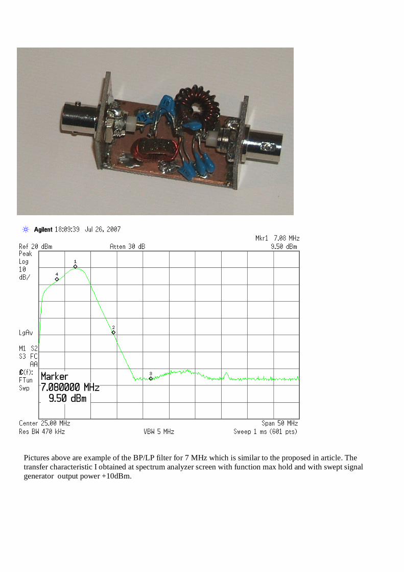
Pictures above are example of the BP/LP filter for 7 MHz which is similar to the proposed in article. The transfer characteristic I obtained at spectrum analyzer screen with function max hold and with swept signal generator output power +10dBm.

BP-LP response for 6m
BP-LP response for 12m and 10m
0.1 50.1 100.1 150.1 180Frequency (MHz)
Graph 1
-100
-80
-60
-40
-20
0
23.9 MHz-12.65 dB
143.6 MHz-49.77 dB
49.92 MHz-0.1902 dB
49 MHz-26.56 dB
87 MHz-66.14 dB
54.52 MHz-0.2732 dB
108 MHz-53.18 dB
DB(|S(1,1)|)Schematic 1
DB(|S(2,1)|)Schematic 1
DB(|S(2,2)|)Schematic 1
1 21 41 61 81 100Frequency (MHz)
Graph 1
-100
-80
-60
-40
-20
0
14.586 MHz-6.095 dB
84.85 MHz-96.52 dB
24.914 MHz-0.2059 dB
28.149 MHz-28.84 dB
56.225 MHz-82.55 dB
29.825 MHz-0.3714 dB
50.11 MHz-42.15 dB DB(|S(1,1)|)
Schematic 1
DB(|S(2,1)|)Schematic 1
DB(|S(2,2)|)Schematic 1
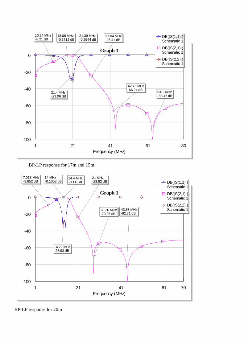
BP-LP response for 17m and 15m
BP-LP response for 20m
1 21 41 61 80Frequency (MHz)
Graph 1
-100
-80
-60
-40
-20
0
10.34 MHz-8.21 dB
64.1 MHz-83.47 dB
18.06 MHz-0.3712 dB
21.4 MHz-23.06 dB
42.75 MHz-66.24 dB
21.39 MHz-0.2544 dB
31.04 MHz-25.41 dB
DB(|S(1,1)|)Schematic 1
DB(|S(2,1)|)Schematic 1
DB(|S(2,2)|)Schematic 1
1 21 41 61 70Frequency (MHz)
Graph 1
-100
-80
-60
-40
-20
0
7.018 MHz-9.652 dB
43.58 MHz-82.71 dB
14.4 MHz-0.113 dB
14.22 MHz-28.93 dB
28.36 MHz-70.25 dB
14 MHz-0.1053 dB
21 MHz-23.92 dB DB(|S(1,1)|)
Schematic 1
DB(|S(2,1)|)Schematic 1
DB(|S(2,2)|)Schematic 1

BP-LP response for 30m
BP-LP response for 40m
1 11 21 31 40Frequency (MHz)
Graph 1
-100
-80
-60
-40
-20
0
7.042 MHz-4.598 dB
30.6 MHz-85.51 dB
10.14 MHz-0.1838 dB
10.18 MHz-28.55 dB
20.91 MHz-51.26 dB
10.96 MHz-0.1949 dB
14.64 MHz-14.06 dB DB(|S(1,1)|)
Schematic 1
DB(|S(2,1)|)Schematic 1
DB(|S(2,2)|)Schematic 1
0.1 10.1 20.1 30.1 40.1 50Frequency (MHz)
Graph 1
-100
-80
-60
-40
-20
0
14.013 MHz-49.863 dB
7.1243 MHz-34.746 dB
43.302 MHz-48.893 dB
28.666 MHz-53.787 dB
7.0636 MHz-0.36507 dB
DB(|S(1,1)|)Schematic 1.$FPRJ
DB(|S(2,1)|)Schematic 1.$FPRJ
DB(|S(2,2)|)Schematic 1.$FPRJ

BP-LP response for 80m BP-LP response for 6m
BP-LP response for 160m
1 6 11 16 17Frequency (MHz)
Graph 1
-100
-80
-60
-40
-20
0
1.825 MHz-8.468 dB
14.18 MHz-52.01 dB
3.501 MHz-0.2103 dB
3.7 MHz-24.02 dB
10.53 MHz-72.99 dB
7.145 MHz-71.91 dB
3.706 MHz-0.2187 dB
DB(|S(1,1)|)Schematic 1
DB(|S(2,1)|)Schematic 1
DB(|S(2,2)|)Schematic 1
1 3 5 7 8Frequency (MHz)
Graph 1
-100
-80
-60
-40
-20
0
2.059 MHz-0.3104 dB
1.784 MHz-0.2363 dB
3.501 MHz-60.94 dB
1.808 MHz-27.13 dB
7.145 MHz-50 dB
5.488 MHz-73.43 dB
DB(|S(1,1)|)Schematic 1
DB(|S(2,1)|)Schematic 1
DB(|S(2,2)|)Schematic 1
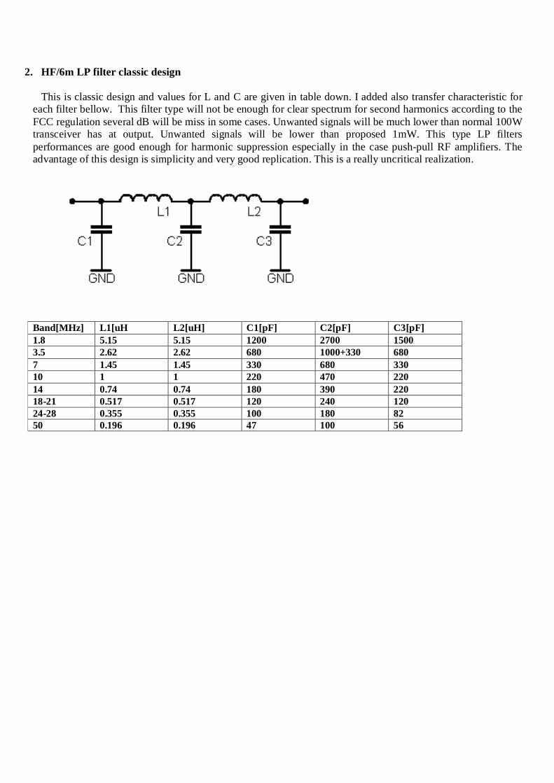
2. HF/6m LP filter classic design
This is classic design and values for L and C are given in table down. I added also transfer characteristic for each filter bellow. This filter type will not be enough for clear spectrum for second harmonics according to the FCC regulation several dB will be miss in some cases. Unwanted signals will be much lower than normal 100W transceiver has at output. Unwanted signals will be lower than proposed 1mW. This type LP filters performances are good enough for harmonic suppression especially in the case push-pull RF amplifiers. The advantage of this design is simplicity and very good replication. This is a really uncritical realization.
Band[MHz] L1[uH L2[uH] C1[pF] C2[pF] C3[pF] 1.8 5.15 5.15 1200 2700 1500 3.5 2.62 2.62 680 1000+330 680 7 1.45 1.45 330 680 330 10 1 1 220 470 220 14 0.74 0.74 180 390 220 18-21 0.517 0.517 120 240 120 24-28 0.355 0.355 100 180 82 50 0.196 0.196 47 100 56
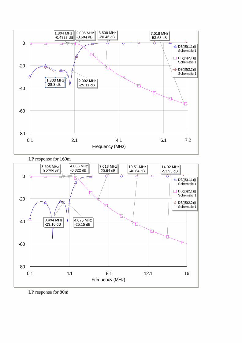
LP response for 160m
LP response for 80m
0.1 2.1 4.1 6.1 7.2Frequency (MHz)
Graph 1
-80
-60
-40
-20
0
1.804 MHz-0.4323 dB
1.803 MHz-28.3 dB
2.002 MHz-25.11 dB
7.018 MHz-53.68 dB
2.005 MHz-0.504 dB
3.508 MHz-20.46 dB
DB(|S(1,1)|)Schematic 1
DB(|S(2,1)|)Schematic 1
DB(|S(2,2)|)Schematic 1
0.1 4.1 8.1 12.1 16Frequency (MHz)
Graph 1
-80
-60
-40
-20
0
4.075 MHz-25.15 dB
3.494 MHz-23.16 dB
4.066 MHz-0.322 dB
14.02 MHz-53.95 dB
10.51 MHz-40.64 dB
7.018 MHz-20.64 dB
3.508 MHz-0.2759 dB
DB(|S(1,1)|)Schematic 1
DB(|S(2,1)|)Schematic 1
DB(|S(2,2)|)Schematic 1

LP response for 40m
LP response for 30m
0.1 10.1 20.1 28Frequency (MHz)
Graph 1
-80
-60
-40
-20
0
28 MHz-55.61 dB
21.26 MHz-43.08 dB
7.006 MHz-0.1242 dB
7.309 MHz-26.86 dB
6.987 MHz-48.08 dB
14.02 MHz-23.16 dB
7.4 MHz-0.153 dB
DB(|S(1,1)|)Schematic 1
DB(|S(2,1)|)Schematic 1
DB(|S(2,2)|)Schematic 1
0.1 20.1 40.1 56Frequency (MHz)
Graph 1
-80
-60
-40
-20
0
42.23 MHz-56.91 dB
20.22 MHz-22.54 dB
10.19 MHz-0.1461 dB
30.21 MHz-41.73 dB
10.11 MHz-34.39 dB
14.49 MHz-5.758 dB
DB(|S(1,1)|)Schematic 1
DB(|S(2,1)|)Schematic 1
DB(|S(2,2)|)Schematic 1
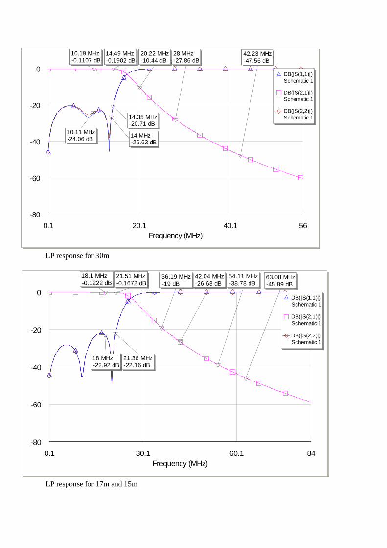
LP response for 30m
LP response for 17m and 15m
0.1 20.1 40.1 56Frequency (MHz)
Graph 1
-80
-60
-40
-20
0
42.23 MHz-47.56 dB
20.22 MHz-10.44 dB
14 MHz-26.63 dB
10.19 MHz-0.1107 dB
28 MHz-27.86 dB
14.35 MHz-20.71 dB
10.11 MHz-24.06 dB
14.49 MHz-0.1902 dB
DB(|S(1,1)|)Schematic 1
DB(|S(2,1)|)Schematic 1
DB(|S(2,2)|)Schematic 1
0.1 30.1 60.1 84Frequency (MHz)
Graph 1
-80
-60
-40
-20
0
63.08 MHz-45.89 dB
54.11 MHz-38.78 dB
42.04 MHz-26.63 dB
36.19 MHz-19 dB
18.1 MHz-0.1222 dB
18 MHz-22.92 dB
21.51 MHz-0.1672 dB
21.36 MHz-22.16 dB
DB(|S(1,1)|)Schematic 1
DB(|S(2,1)|)Schematic 1
DB(|S(2,2)|)Schematic 1

LP response for 12m and 10m
LP response for 6m
0.1 40.1 80.1 120Frequency (MHz)
Graph 1
-80
-60
-40
-20
0
115.6 MHz-58.71 dB
75.14 MHz-38.94 dB
56.1 MHz-24.64 dB
49.7 MHz-18.32 dB
30.01 MHz-0.1725 dB
24.95 MHz-23.14 dB
24.83 MHz-0.134 dB
30.02 MHz-22.3 dB
DB(|S(1,1)|)Schematic 1
DB(|S(2,1)|)Schematic 1
DB(|S(2,2)|)Schematic 1
0.1 50.1 100.1 150Frequency (MHz)
Graph 1
-80
-60
-40
-20
0
150 MHz-43.97 dB
100.4 MHz-24.43 dB
54.1 MHz-0.1501 dB
49.95 MHz-0.1229 dB
50.02 MHz-28.85 dB
54.11 MHz-24.37 dB
DB(|S(1,1)|)Schematic 1
DB(|S(2,1)|)Schematic 1
DB(|S(2,2)|)Schematic 1

3. HF/6m LP-BP Filter Design Simple as Possible
This design is derivate of classic LP (low pass) to BP (band-pass) with minimum built in components
two L and five C. The values for each band are given in table down. I added also transfer characteristic for each filter below. The idea for this realization comes from RSGB Radio Communication Handbook eight edition BP-LP from DJ8ES for 2m [page 9.37].
Band[MHz] L1[uH L2[uH] C1[pF] C2[pF] C3[pF] C4[pF] C5[pF]
1.8 6.8 6.8 1500 1000 1000 910 1500 3.5 4.7 4.7 560 330 220 330 560 7 2.2 2.2 470 240 150 240 470
10 1.8 1.8 330 150 68 150 330 14 1.5 1.5 240 82 22 82 240
18-21 1 1 100 56 33 56 100 24-28 0.47 0.47 120 68 56 68 120
50 0.27 0.27 82 39 18 39 82

LP response for 160m
LP response for 80m
0.1 2.1 4.1 6.1 7.2Frequency (MHz)
Graph 1
-80
-60
-40
-20
0
1.004 MHz-4.533 dB
2.073 MHz-0.3593 dB
3.476 MHz-26.21 dB
2.095 MHz-23.37 dB
1.828 MHz-0.3152 dB
7.2 MHz-61.99 dB
1.806 MHz-23.99 dB
4.028 MHz-34.17 dB
DB(|S(1,1)|)Schematic 1
DB(|S(2,1)|)Schematic 1
DB(|S(2,2)|)Schematic 1
0.1 5.1 10.1 14Frequency (MHz)
Graph 1
-80
-60
-40
-20
0
3.476 MHz-0.2625 dB
4.008 MHz-29.04 dB
1.827 MHz-9.347 dB
14 MHz-60.12 dB
3.486 MHz-28.41 dB
4.028 MHz-0.2887 dB
7.063 MHz-27.89 dB
10.16 MHz-45.58 dB
DB(|S(1,1)|)Schematic 1
DB(|S(2,1)|)Schematic 1
DB(|S(2,2)|)Schematic 1

LP response for 40m
LP response for 30m
0.1 10.1 20.1 28Frequency (MHz)
Graph 1
-80
-60
-40
-20
0
7.298 MHz-35.58 dB
7.301 MHz-0.398 dB
1.793 MHz-15.74 dB
28 MHz-71 dB
7.02 MHz-23.3 dB
3.811 MHz-7.847 dB
6.957 MHz-0.378 dB
21.08 MHz-57.98 dB
10.16 MHz-18.93 dB
14.04 MHz-38.02 dB
DB(|S(1,1)|)Schematic 1
DB(|S(2,1)|)Schematic 1
DB(|S(2,2)|)Schematic 1
0.1 10.1 20.1 30Frequency (MHz)
Graph 1
-80
-60
-40
-20
0
3.811 MHz-15.19 dB
7.063 MHz-4.856 dB
20.21 MHz-41.82 dB
10.15 MHz-26.98 dB
10.16 MHz-0.4333 dB
30 MHz-61.02 dB
14.35 MHz-21.95 dB
DB(|S(1,1)|)Schematic 1
DB(|S(2,1)|)Schematic 1
DB(|S(2,2)|)Schematic 1
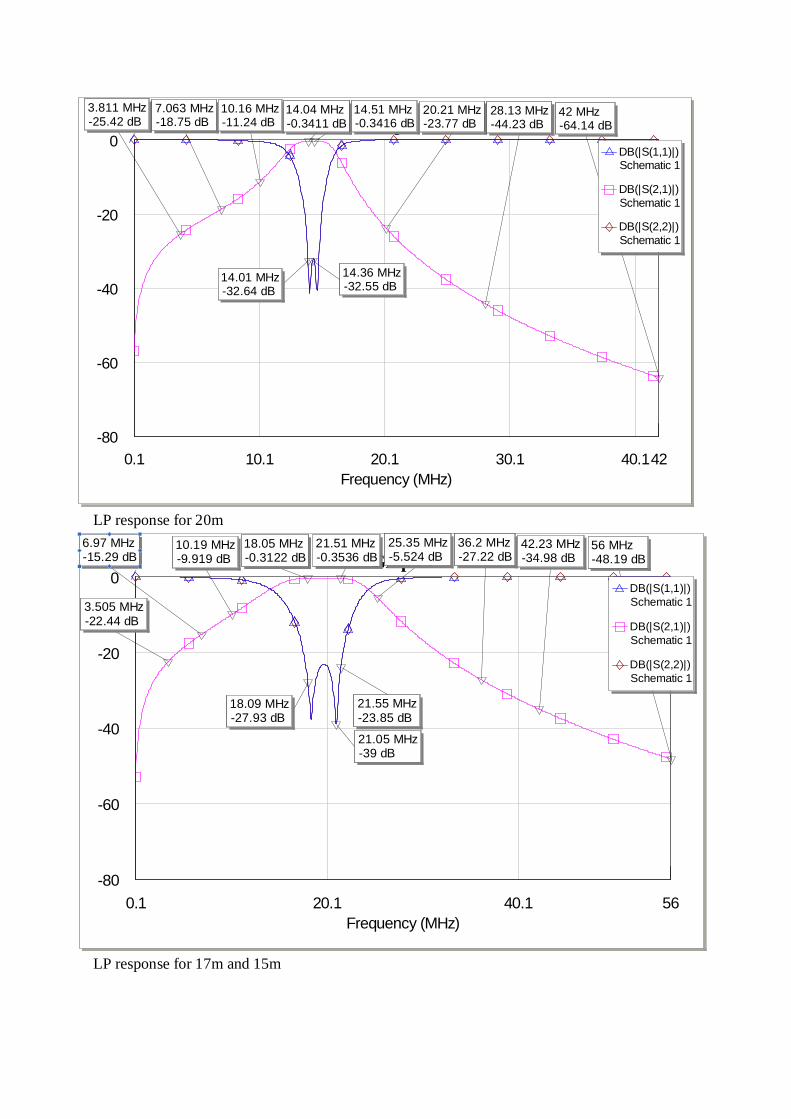
LP response for 20m
LP response for 17m and 15m
0.1 10.1 20.1 30.1 40.142Frequency (MHz)
Graph 1
-80
-60
-40
-20
0
42 MHz-64.14 dB
14.36 MHz-32.55 dB
14.51 MHz-0.3416 dB
3.811 MHz-25.42 dB
7.063 MHz-18.75 dB
20.21 MHz-23.77 dB
14.01 MHz-32.64 dB
10.16 MHz-11.24 dB
28.13 MHz-44.23 dB
14.04 MHz-0.3411 dB
DB(|S(1,1)|)Schematic 1
DB(|S(2,1)|)Schematic 1
DB(|S(2,2)|)Schematic 1
0.1 20.1 40.1 56Frequency (MHz)
Graph 1
-80
-60
-40
-20
0
6.97 MHz-15.29 dB
3.505 MHz-22.44 dB
56 MHz-48.19 dB
18.09 MHz-27.93 dB
21.55 MHz-23.85 dB
21.05 MHz-39 dB
36.2 MHz-27.22 dB
42.23 MHz-34.98 dB
21.51 MHz-0.3536 dB
10.19 MHz-9.919 dB
25.35 MHz-5.524 dB
18.05 MHz-0.3122 dB
DB(|S(1,1)|)Schematic 1
DB(|S(2,1)|)Schematic 1
DB(|S(2,2)|)Schematic 1
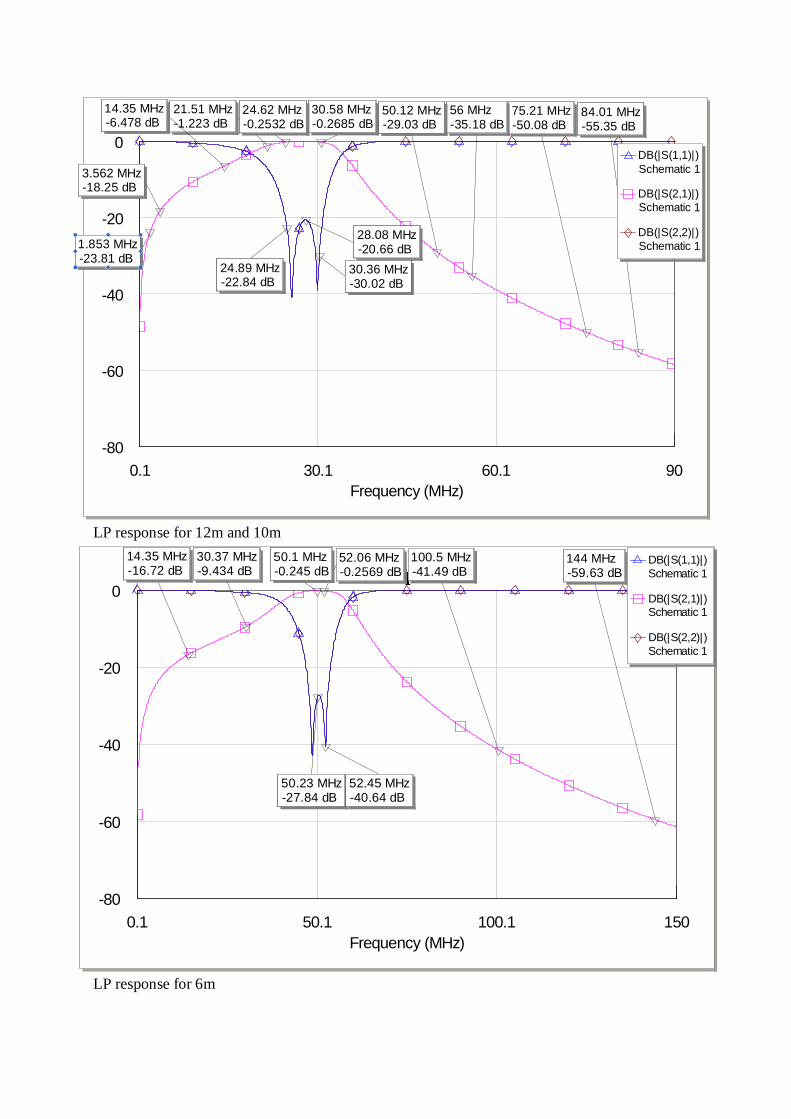
LP response for 12m and 10m
LP response for 6m
0.1 30.1 60.1 90Frequency (MHz)
Graph 1
-80
-60
-40
-20
0
1.853 MHz-23.81 dB
3.562 MHz-18.25 dB
84.01 MHz-55.35 dB
75.21 MHz-50.08 dB
56 MHz-35.18 dB
28.08 MHz-20.66 dB
30.36 MHz-30.02 dB
24.89 MHz-22.84 dB
30.58 MHz-0.2685 dB
50.12 MHz-29.03 dB
21.51 MHz-1.223 dB
14.35 MHz-6.478 dB
24.62 MHz-0.2532 dB
DB(|S(1,1)|)Schematic 1
DB(|S(2,1)|)Schematic 1
DB(|S(2,2)|)Schematic 1
0.1 50.1 100.1 150Frequency (MHz)
Graph 1
-80
-60
-40
-20
0
144 MHz-59.63 dB
30.37 MHz-9.434 dB
50.23 MHz-27.84 dB
52.45 MHz-40.64 dB
100.5 MHz-41.49 dB
52.06 MHz-0.2569 dB
50.1 MHz-0.245 dB
14.35 MHz-16.72 dB
DB(|S(1,1)|)Schematic 1
DB(|S(2,1)|)Schematic 1
DB(|S(2,2)|)Schematic 1

Summary It is possible realized very simple LP or LP-BP filter at the output of SDR transceivers Genesis G****, AVALA series, HF CER-01 transceivers or any other transceiver as minimal number component approach. The number of turns on ring cores or air coils can be easy calculated with freeware software written by Wilfried DL5SWB. Please take care about component quality build in these filter because un-adequate component lead to output transistor destruction!!! Some details you will be able read in references and in the articles which are in preparation and they will be published very soon at these WEB pages. The filters are with 3 equal coils! For BP filters are very important component accuracy to obtain good RF specifications!
I wish you successful BP realization and I apologize for some possible mistakes. I made great effort to
share my projects with all who are interesting for. Anyway, send me your comments positive or negative, results or photos of your realization please.
August 2008, rewritten July 2009 VY 73/72 and GL in homebrew Tasa YU1LM/QRP [email protected] [email protected]
References:
1. www.yu1lm.qrpradio.com 2. www.genesisradio.com.au 3. http://www.linear.com/designtools/software 4. M.Martin DJ7VY :A New Type of Preamplifier for 145 MHz and 435 MHz Receivers/UKW berichte
1/1978 5. www.dl5swb.de 6. Ed Wetherhold W3NQN – Clean Your Signal with Band-Pass Filter –part1 ), QST May 1998(pages
44-48) , 7. Ed Wetherhold W3NQN – Clean Your Signal with Band-Pass Filter –part1 ), QST June 1998(pages
30-42), 8. Lew gordon K4VX-Band-Pass Filters for HF Transceivers-QST 09/1988(pages 17-23) 9. http://www.bavarian-contest-club.de/projects/bandpassfilter/100W-BP.pdf