the ohio state university research foundation · report 4 the ohio state university research...
TRANSCRIPT

,1' :v
ItC / /4 7)Nq1drJ63LCf 7* ./r A ldco
RF Project 3329Report 4
THE OHIO STATE UNIVERSITY
RESEARCH FOUNDATION1314 KINNEAR ROAD COLUMBUS, OHIO 43212
EFFECTS OF WEIGHTLESSNESS ON THE DEVELOPMENT OF THE
VESTIBULAR APPARATUS AND OCULAR NYSTAGMUS IN THE RAT
Dr. David L. Clark
Department of Anatomy
1 October 1971 - 30 September 1972
NASA, AMES RESEARCH CENTERMoffett Field, California
Contract No. NA
Reproduced by ,
NATIONAL TECHNICAL -' </ .... ~ J INFORMATION SERVICE .
US Department of Commerce/WRIGI1TL ~ 5 EE lSpringfield, VA. 22151 WEIGASA
1 RFFRCTs S Op1J3
VESTIB R S ON THE DEVLOSC
dost. M.c"a .E OF. Tr 3-t;irtj~~ IB LAR PPAR TUS A D OCULAV MyTNfU
FofindatA? (O ate u iv. eCSCLR06cCG3,0 4 63152 �1 12
I0 I .1 D u
", .1 ,
https://ntrs.nasa.gov/search.jsp?R=19730008385 2018-07-13T14:58:37+00:00Z

RF Project........33.2.9-.Al.
Report N o ................... 4.............
.............................................. ............................................
REPORTBy
THE OHIO STATE UNIVERSITYRESEARCH FOUNDATION
1314 KINNEAR RD.
COLUMBUS, OHIO 43212
To NASAl AMES RESEARCH CENTERTo .................................................................................... ................................................. a.
,,,,,,,,,,,,,,,,,,,,,,Mo ,fett Field, Cal if ornia 92+035........................ .................M.o...f..e......... ...F..e.........C... .~...if...i............~..... 35 .............................................
.......................................... .. .. .. .. . .,.. .... ........................ .............................. .......................
On ..................... EFFECTS OF WEIGHTLESSNESS ON THE DEVELOPNENTOn ~~~~~~~~~~........................................E...F......................................L........s....Es.s.. ..N ...T . .........~....E. .. E..... ............
........................................................... ............... .............. US.. ....... .......... ............................. ................O F THE V TIB...................U LA R APPA................. ... ... .. ........... .... .... .......... R A ... .................................................................................
,,,,,,,,,,,,,,,,,,,NY ..... S,,T,,A,.G M,,JS,. .,'IIT,; ER A.$
For the period. ...1 October 1971 ...- .30 ..Septemb..er. 1972..
Subm itted by ......... Dr.. .D avid... L ...... Clark ............................................................
......... ... ...................... ................................................................................A nat
Date ...............18 .December 1.972
I

TABLE OF CONTENTS
Page
PART I
CONSTRUCTION OF TEE CHRONIC 2G CENTRIFUGE 1
PART II
INTRODUCTION 12
MATERIALS AND METHODS 12
PROCEDURE 13
RESULTS 13
Stationary Rail Test 13Rotating Rail Test 14
DISCUSSION 14
PART III
INTRODUCTION 19
Physiological Review and Mathematical Basis 19
1. Vestibular Apparatus 192. System Analysis 20
RESULTS 33
Time Constants of the System 33Input Threshold Level of the System 35
DISCUSSION AND CONCLUSION 44
APPENDIX 47
ii
LIST OF FIGURES
FigureNo. Page
Part I
1 Jig developed to form and weld aluminum cage holder 3
2 Cage holder for standard laboratory cage measuring18" x 10" x 7" deep 3
3 Detail of gimbal unit, with brass ball and supportstud, which allows swivel of cage holder on centrifuge 4
4 Cages on test device rotating at about 100 rpm 4
5 Radius arms are mated to hub assembly by sleeve fitover stud and secured by bolts 5
6 Hub with radius arms attached (Maximum radius is5.25 ft) 5
7 Radius extensions mated to radius arms (Maximumradius is 10.5 ft) 7
8 Wooden mock-up of centrifuge hub with top supportdisk and gussets in place 7
9 Wooden mock-up of centrifuge hub with top support diskremoved revealing position of studs 8
10 Completed hub assembly welded into a single unit readyfor assembly 8
11 Six-foot square centrifuge support base 9
12 Six-foot square centrifuge support base with crossbraces and bolt-on legs 9
13 Pedestal assembly with drive motor, speed reducer,support bearings, and drive shaft 10
14 Completed centrifuge with cages holders and cagespositioned at maximum radius 10
PART III
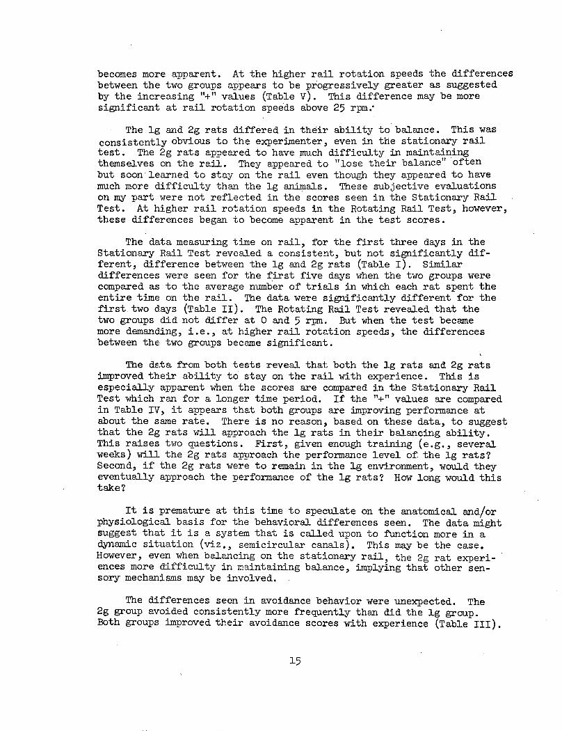
1 (a) The simplified horizontal vestibulo-ocular reflexarc in block diagram. (b) The arrows indicate thedirection of information flow. (c) The simplifiedtransfer function with input [a(s)] and output [V(s)]. 21
iii

LIST OF FIGURES - (Continued)
FigureNo. Page
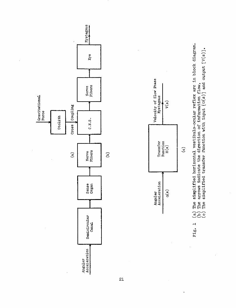
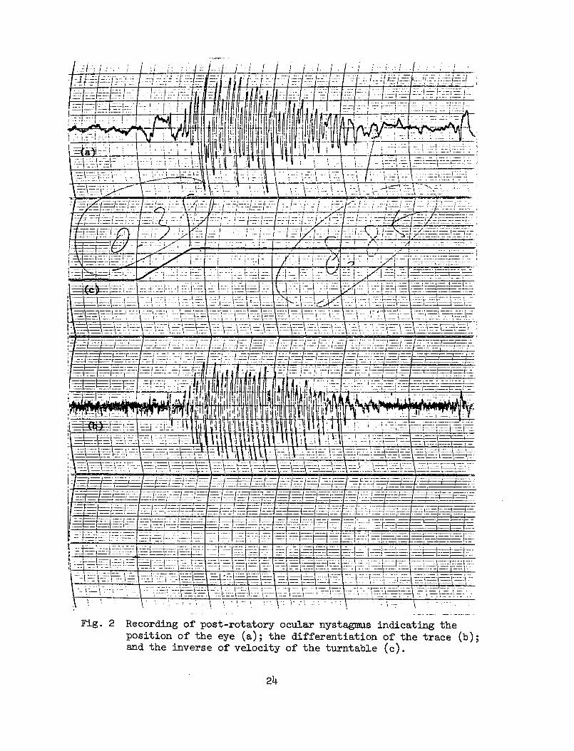
2 Recording of post-rotatory ocular nystagmus indicatingthe position of the eye (a); the differentiation ofthe trace (b); and the inverse of velocity of theturntable (c). 24
3 Idealized form of the horizontal semicircular canal. 25
4 (a) The angular acceleration pulse((t) = a[u(t) - u(t - T)] ; (b) the pulse response
~(t) with ~min and Tp. 29
5 Mean duration as a function of inverse decelerationrate for six lg rats. The slopes of the three straightlines give the time constants of the system: 9.05,1.30, and 0.39. 36
6 Mean duration as a function of inverse decelerationrate for eight 2g rats. The missing time constantof 1.30 shows the difference between lg and 2g rats. 37
7 A predictor-corrector method indicates the value ofH/A, 9.1, approximately. 39
8 The latency of nystagmus following the onset ofconstant angular deceleration for lg rats. Thethreshold deceleration is 5°/sec2. 42
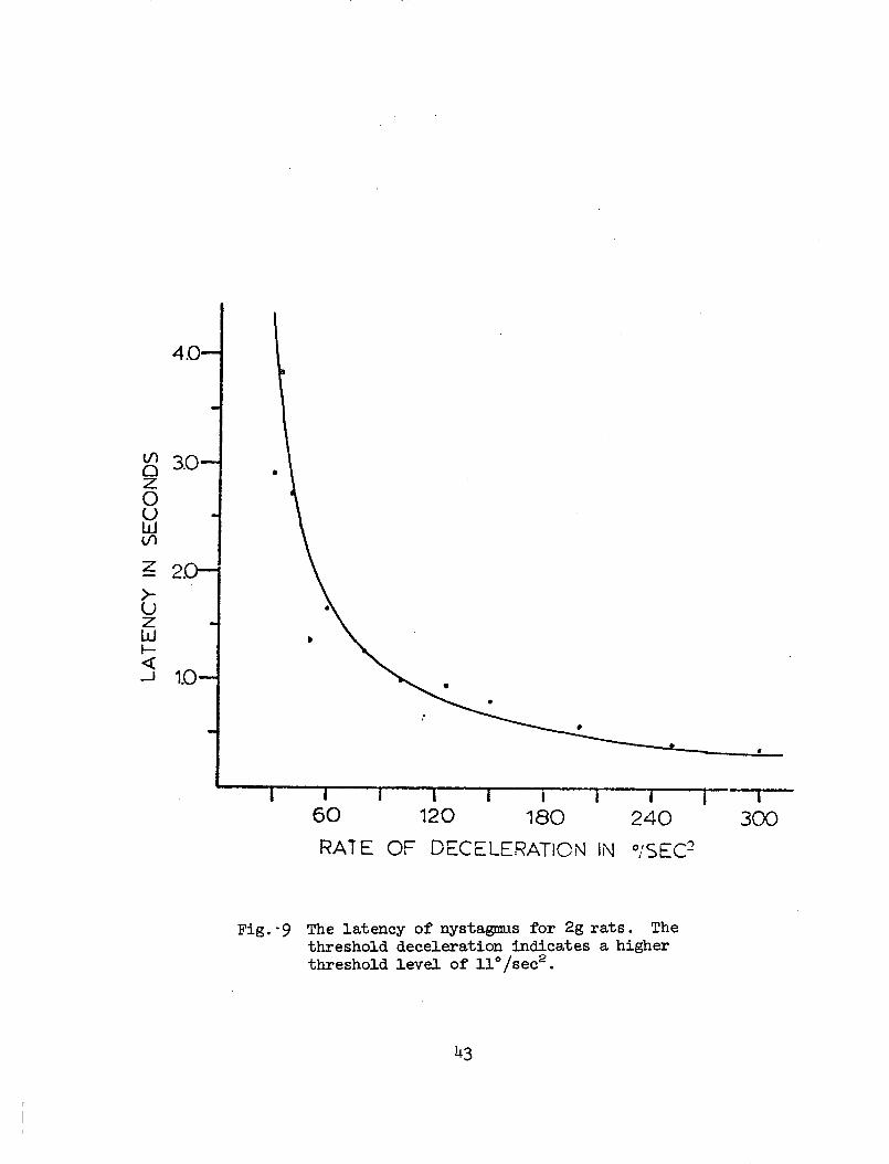
9 The latency of nystagmus for 2g rats. The thresholddeceleration indicates a higher threshold level of11°/sec2 . 43
10 (a) The mathematical model of lg for accelerationinput. (b) The model of 2g with a missing utricularterm and a higher threshold. 46
iv

LIST OF TABLES
TableNo. Page
PART II
1 Stationary Rail Test 17
2 Stationary Rail Test 17
3 Stationary Rail Test 17
4 Rotating Rail Test 18
5 Rotating Rail Test 18
6 Rotating Rail Test 18
PART III
1 The means and standard deviations of duration ofpost-rotatory nystagmus for lg rats 34
2 The means and standard deviations of duration ofpost-rotatory nystagmus for 2g rats 34
3 The time constants of lg and 2g rats 38
4 Mean duration of post-rotatory nystagmus (Tp) forlg rats 38
5 The mean and standard deviation of latency ofnystagmus for lg rats 40
6 The mean and standard deviation of latency ofnystagmus for 2g rats 41
v

PART I
CONSTRUCTION OF THE CHRONIC 2G CENTRIFUGE
In formulating design characteristics of the Chronic 2g Centrifuge,several constraints were considered in order to ensure the constancy andreliability of vestibular data retrieved from the rats housed on boardthe centrifuge. A prime concern was that of reliability. The datawould have little meaning if the unit were inoperable for any amount oftime, requiring repair or maintenance. It was predetermined that anymaintenance required should be scheduled maintenance which could beadministered at intervals of at least several months. The centrifugemust also run continuously and at a constant velocity. The centrifugewas to have as large a radius arm as possible in order to minimize thecoriolis phenomena effects that could alter vestibular system response.Both the velocity and radius, however, were to be infinitely variable,within certain specified limits, in order to provide flexibility inexperimental design if the need arose at a future date. The centrifugewas to provide living space for a minimum of 20 rats, which were to behoused in standard 18" x 10" x 7" deep laboratory cages. The rats wereto receive food and water ad libitum. It was emphasized that wobbleand vibration be kept to a minimum. The cages were to be oriented onthe radius arm such that at any speed, from zero to maximum velocity,the floor of the cage was to be perpendicular to the resultant gravityvector.
The Electrical Shop in the Department of Electrical Engineering atThe Ohio State University agreed to design and construct the centrifuge.They agreed to a six-month deadline but requested that the design stagebe kept to a minimum in order to assure completion with the six-monthperiod. This request proved to be an asset in speeding construction andcompletion of the centrifuge within the allotted time span.
The dimensions of the centrifuge were dictated by the size of theroom in which it was to be housed. It was decided that the maximumradius was to be 10.5 ft. By dividing the length of the circumferenceby the length of each cage, it was determined that we could easilyaccommodate 20 cages at the maximum radius. At shorter radii fewercages can be accommodated at any one particular radius because of thereduced circumference. We have the option, however, of staggering cagesat several different radii. This will be available in later experimentsin which we wish to expose different populations of experimental animalsto different g levels while maintaining a constant velocity of rotationand coriolis phenomena. The design includes the potential of positioninga single cage or a vertical stack of several cages over the center axisof the centrifuge, thus positioning the rats at essentially zero radius,lg. However, since they will turn at the same velocity as the rest ofthe centrifuge they will be exposed to the identical potential coriolisphenomena.
1

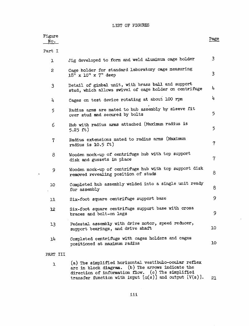
The standard polyethylene laboratory cages are individually heldin an aluminum cage holder. The cage holder is formed and heliarcwelded on a jig (Fig. 1). The individual cage slips into the cageholder (Fig. 2) and can be easily removed for cage cleaning. This sizecage can accommodate up to four adult rats or one rat with a litter.
A gimbal cage support suspension device was accepted followingtests on a prototype (Fig. 2). The gimbal consists of a ball and socketjoint and a horizontal axis (Fig. 3). The ball is made of brass andcan rotate sufficiently within the socket assembly to maintain alignmentof the horizontal axis. The cage holder is suspended from the ball andsocket by a short support stud riveted by means of a flange to the cagesupport bracket (Fig. 3). The stud slips through a hole in the brassball and the assembly is secured by a circlip at the end of the stud.This gimbal has proved to present a minimum of friction and is satis-factory in maintaining the floor of the cage perpendicular to thegravity vector, regardless of speed of rotation (Fig. 4).
Food and water are provided for the rats by a conventional pellettray and water bottle holder incorporated into the cage lid. Inadver-tent water loss from the water bottle has not proved to be a problem.This may be partially due to the fact that we have selected dropperspouts with a relatively small diameter opening and have cut the spoutshaft to keep it as short as possible and still allow the rat easyaccess to the water.
Each cage support is anchored to its pair of radius arms or radiusarm extensions by means of two pinch clamps, one directly below eachgimbal. The clamp is secured by tightening a single bolt. The clampholds the cage support in its position by friction and the system isdesigned so that the cage may be positioned at any radius from the hubto the outer limit of the radius arm extensions. The clamps are alignedon the box channels making up the radius arms and radius arm extensionsso that if both cage clamps should fail, which is unlikely, the cagewould slide to the maximum radius of the radius arms or radius extensionarms. They would not lose their attachment to the centrifuge and thuscould not fly off the centrifuge producing a potential hazard to personnel.
The simplest and most rigid radius arm construction was employed.Box aluminum alloy channel (2" x 4") was chosen for radius arms andradius arm extensions. This construction gives the greatest rigidityand strength per pound weight and, at the same time, simplifies themethod of assembly. At critical points such as the point at which eachradius arm is joined to the hub and where the extension arm is attached,a sleeve fit was used for strength and ease of assembly. The internaland external sections of each sleeve were then secured with bolts (Fig. 5).
Each radius arm assembly was divided into two parts. The inner isthe radius arm proper and the outer is the radius arm extension. Thismethod was devised for ease of construction and also to provide more
2
_
Fig. 1 - Jig developed to form and weld aluminum cage holder
_
Fig. 2 - Cage holder for standard laboratory-cage measuring l8" x 10" x 7" deep

Fig. 3 - Detail of gimbal unit, with brass ball and support stud, which allows swivel of cage holder on centrifuge
Fig. h - Cages on test device rotating at about 100 rpm (Note cage tilt in response to combined gravitational and centrifugal forces)

Fig. 5 - Radius arms are mated to hub assembly by sleeve fit over stud and secured by bolts
Fig. 6 - Hub with radius arms attached (Maximum radius is 5.25 ft)
5

flexibility in the operation of the centrifuge. With just the radiusarms secured to the hub, the maximum effective radius of the centrifugeis 5.25 ft (Fig. 6). This considerably reduces the weight of thecentrifuge wheel and also reduces wind-loading. The power requirementsfor driving this effectively smaller centrifuge are reduced and thus,with the power unit available, higher rotational velocities can beachieved. The increase in rotational velocity could produce higher glevels or higher potential coriolis stimulation or both, on the experi-mental design.
The radius arm extension is a "Y" shaped extension arm. The baseof the "Y" plugs into the terminal end of the radius arm and extendsthe radius of the centrifuge to 10.5 ft (Fig. 7). The use of the radiusarm extension increases the total weight and wind-loading force of thecentrifuge wheel. The increased radius, however, reduces the potentialcoriolis effect generated at any particular g level produced. This hasproved to be an important stimulus parameter when the vestibular systemis being examined.
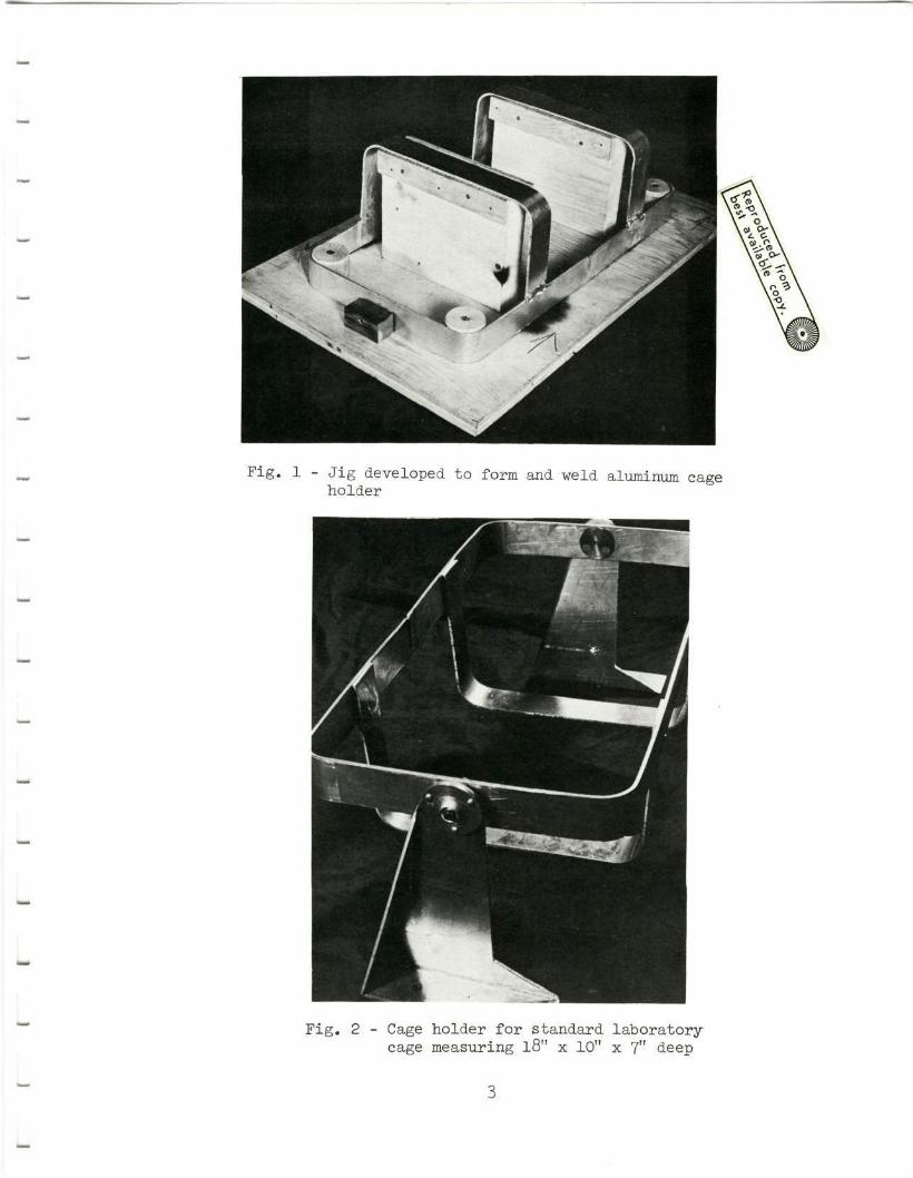
The hub assembly is the critical part of the centrifuge. It isrequired to anchor the radius arms, transmit torque from the verticalshaft to the radius arms, and transmit the entire weight of the super-structure to the vertical drive shaft and its support bearing. In orderto ensure success of the hub assembly construction a careful design wascompleted and a wooden mock-up was built (Figs. 8 and 9). It wasdecided that the hub be constructed as a single welded unit in order toprovide strength. The same aluminum alloy was used in order to helpreduce weight. The hub assembly is constructed of two 0.5-inch-thickplates 22 inches in diameter. They fit around a 4-inch outside diametercenter sleeve 13.5 inches long. A steel quick-disconnect pulley hubfits into each end of the sleeve. These pulley hubs are keyed for atwo-inch shaft. The circular plates are strengthened by five triangulargussets welded between the plate and center sleeve on both the upperand lower side of the assembly (Fig. 10).
Twenty specially welded and machined box studs were incorporatedinto the hub assembly between the circular disks. Each stud is 15 incheslong and is individually fitted to accept its corresponding radius arm,with a minimum of clearance (Fig. 10). The individual components ofthe hub are heliarc welded to form an integral assembly.
The base is made of four-inch steel channel welded into a six-foot square box frame (Fig. ll). Two parallel cross braces directlysupport the load and transfer it to the box frame directly and also bymeans of four cross angle braces. In order to achieve added supportand stability, each side of the box frame is provided with a bolt-onleg that adds ten feet to the support base in each direction (Fig. 12).
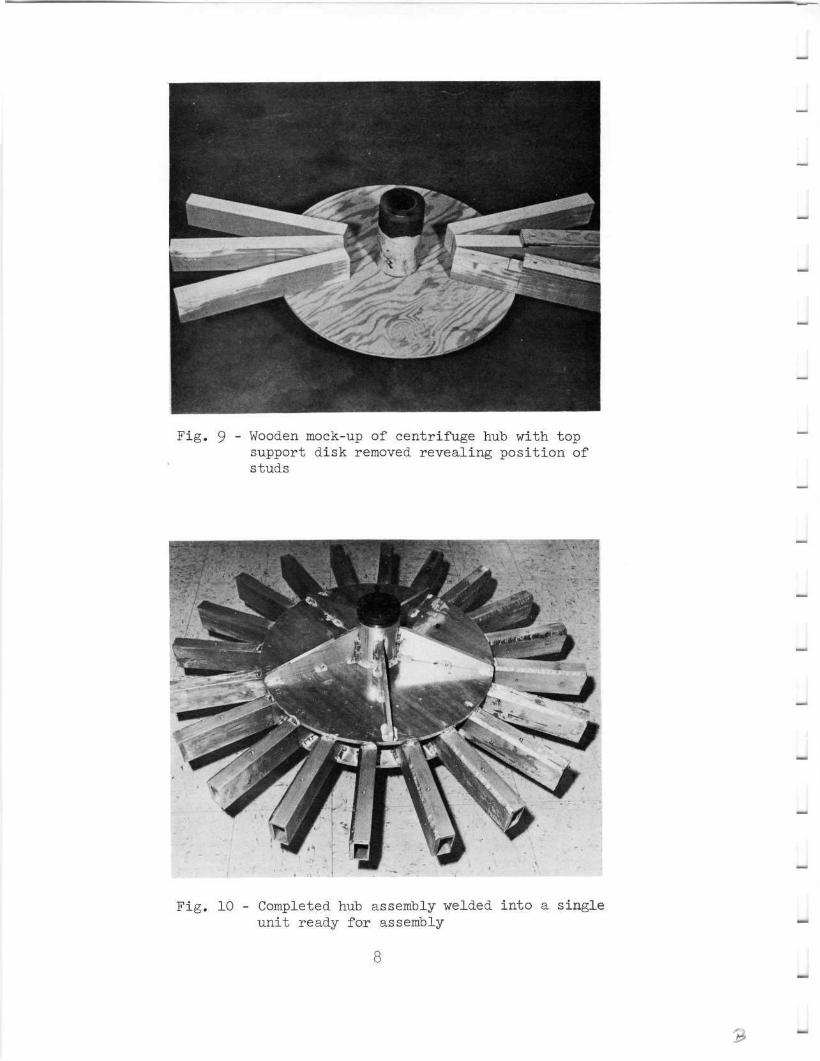
The pedestal assembly incorporates the drive motor, speed reducer,drive shaft, and support bearings (Fig. 13). Four hollow steel cylinders,
6

_
Fig. 7 - Radius extensions mated to radius arms (Maximum radius is 10.5 ft)
_
Fig. 8 - Wooden mock-up of centrifuge hub with top support disk and gussets in place
_
Fig. 9 - Wooden mock-up of centrifuge hub with top support disk removed revealing position of studs
_
_
_
_
_
_
Fig. 10 Completed hub assembly welded into a single unit ready for assembly
8
_
_
J
_
_
_

Fig. 11 - Six-foot square centrifuge support base (Center post represents axis of centrifuge)
L
_
_
_
_
Fig. 12 - Six-foot square centrifuge support base with cross braces and bolt-on legs (At left is pedestal assembly)
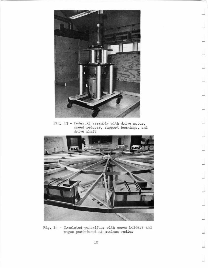
Fig. 13 - Pedestal assembly with drive motor, speed reducer, support bearings, and drive shaft
_
_
Fig. Ik - Completed centrifuge with cages holders and cages positioned at maximum radius
J
_
_
10
_

measuring 3.5 x 22.5 inches, support the base plates of the pedestalassembly. Four hollow steel cylinders, 3.5 x 9.5 inches, are bolted tothe base plate and support the upper plate of the pedestal assembly.The steel base plate is 20 x 20 x 1 inch thick and is machined on theupper and lower surfaces to provide a smooth flat surface. The steelupper plate is 16 x 16 x 1 inch thick.
The centrifuge wheel weight and maximum diameter were taken intoconsideration in estimating the power required to drive the centrifuge.It was found that the leading edge of all cages as they rotated displaceda considerable quantity of air, thus developing a wind-loading forceopposing the rotation of the centrifuge. Several tests were attemptedto determine a value for this force, and a rough estimate was determined.In addition, it was found that the wind-loading effect on the leadingedge of the combined radius arms also contributed to this force. Basedon these estimates it was concluded that a three-horsepower directcurrent motor would be adequate to drive the centrifuge within thespeed ranges necessary to generate at least 2g at any point along theradius arm of the centrifuge.
The drive motor selected is a General Electric, Type L186ATC,three-horsepower direct current motor. It is suspended in a verticalposition in the base of the pedestal. It is coupled directly to aBoston Gear Optimount 17:1 flanged speed reducer. The speed reducer isbolted to the underside of the base plate and accepts the 2 7/16-inchkeyed drive shaft. The drive shaft reduces to a two-inch diameter abovethe bearing supports. The maximum motor speed is 1750 rpm. The speedreducer allows the output drive shaft to turn at a maximum of about100 rpm. Tests of the completed centrifuge have shown that maximumspeed can be approximated with the radius arm and inner ring assembled(Fig. 14). With the radius arm extensions added, the maximum speed isapproximately 30 rpm. The only maintenance required is to change thespeed reducer oil once every 40 days, and to periodically inspect andreplace the motor brushes.
Centrifuge speed is controlled by a Boston Gear Ratiotrol, producedby the Boston Gear Division of North American Rockwell. This device isa full-wave, solid-state SCR control and utilizes modular constructionand transistorized circuitry, including integrated circuits. The controlwill accelerate the centrifuge from zero to a present velocity. It willmaintain this speed continuously within +1% of motor base speed.
ll

PART II
INTRODUCTION
The vestibular system of equilibrium includes both afferent andefferent components. The sensory end organ is made up of two functionalsubunits. One of these is sensitive to gravity and linear accelerationand the second of these is sensitive to turning movements of the head,viz., angular acceleration. Linear acceleration is detected by the maculaof the utriculus and possibly the macula of the sacculus. Angular accer-eration is detected by the cristae ampullares of the three semicircularcanals. The vestibular end organ provides the central nervous system withinformation as to the position of the head with respect to gravity and theacceleration of the head in space. The efferent components of this systemare related to antigravity musculature, muscles associated with movementsof the head and neck, and extraocular muscles. In addition, the vestibularsystem has been associated with the autonomic nervous system and arousal.
Two other sensory systems also play a role in maintenance of equili-brium. First, the visual system functions primarily to maintain a visualhorizon. Second, the proprioceptive system provides information as tothe position of the head with respect to the body, the position of limbswith respect to the body, and the position of the limbs with respect tothe substratusm. All three of these systems function together in orderto assess the position of the head in space, the position of the headwith respect to the body, and the position of the limbs relative to thebody and the substratusm.
The exact role played by each of these systems, or by the individualparts of each system, is not yet clearly known. In this study an attemptwas made to establish a quantitative measurement of the ability of thewhite rat to utilize these equilibrium systems in order to maintain hisbalance during a dynamic situation.
MATERIALS AND METHODS
Two groups of rats were utilized. One group, the lg controls, wereadult rats that had been raised under standard laboratory conditions underthe effects of the earth standard gravity of lg. The second group, the2g experimentals, were adult rats that had been maintained on a centrifugefor a minimum of 60 days, 24 hours per day.
The centrifuge was a small table top device measuring about 1 m indiameter. In order to produce the required 2g environment, the centri-fuge was rotated at 60 rpm. The cages were tilted inward about 30° inorder to position the 2g gravity vector perpendicular to the floor of thecage. Both groups of rats received food and water ad libidum.
12

The device used to test the dynamic equilibrium characteristics ofthe rats was designed after the rail device for monkeys, described byIgarashi (1968). The rat rail device measures 3 ft. long, l1 ft. wideand 2 ft. high. Extending beyond the test box are two start boxes, onelocated at each end. Each is separated from the test box by a slidingdoor. A rail, 1 inch in diameter, runs the length of the box and iscross-shaped in cross-section. The floor of the start boxes and thetest box is an electric shock grid. The rail is at the same level asthe floor of the start boxes, and is 4 inches above the electrified gridfloor of the test box. The rail is connected to a D.C. motor and therate of rotation of the rail can be controlled from 0-25 rpm.
PROCEDURE
During a single testing session, a rat was placed in the start boxfor 15 seconds at one end of the rail. The sliding door was raised anda light turned on at the opposite end of the test box. After fiveseconds the grid in the start box was electrified. The rat was allowedto remain in the test box for up to 60 seconds. There were ten lg con-trol and ten 2g experimental rats. Each rat was tested first in thestationary rail test; i.e., each animal was run for ten trials each dayfor ten consecutive days. Following the stationary rail test, each ratwas then tested in the rotating rail test. Each animal was run for onetrial at each of the following rail rotation speeds: 0, 5, lO, 15, 20,and 25 rpm. The procedure for the rotating rail test was continued forthree consecutive days. All 2g rats were returned to the 2g centrifugefollowing completion of tests each day. All testing was done at lg.
Three sets of data were collected from each group of animals foreach trial. First, it was determined if the rat actively avoided theshock in the start box that was initiated five seconds after the slidingdoor was raised. Second, the total time spent on the rail was recorded.Third, it was determined if the animal remained on the rail during theentire one-minute trial. The last two sets of data are similar in thatthey both are a measure of the animal's ability to maintain balance.
RESULTS
Stationary Rail Test
There was no significant difference between the lg and 2g rats intheir ability to balance using time spent on rail as a measure. TableI indicates that by the fourth day of testing, both groups spent theentire sixty seconds on the rail. During the first three days of testingthe 2g animals tended to fall earlier in the trial, but the group dif-ferences are not significant.
13
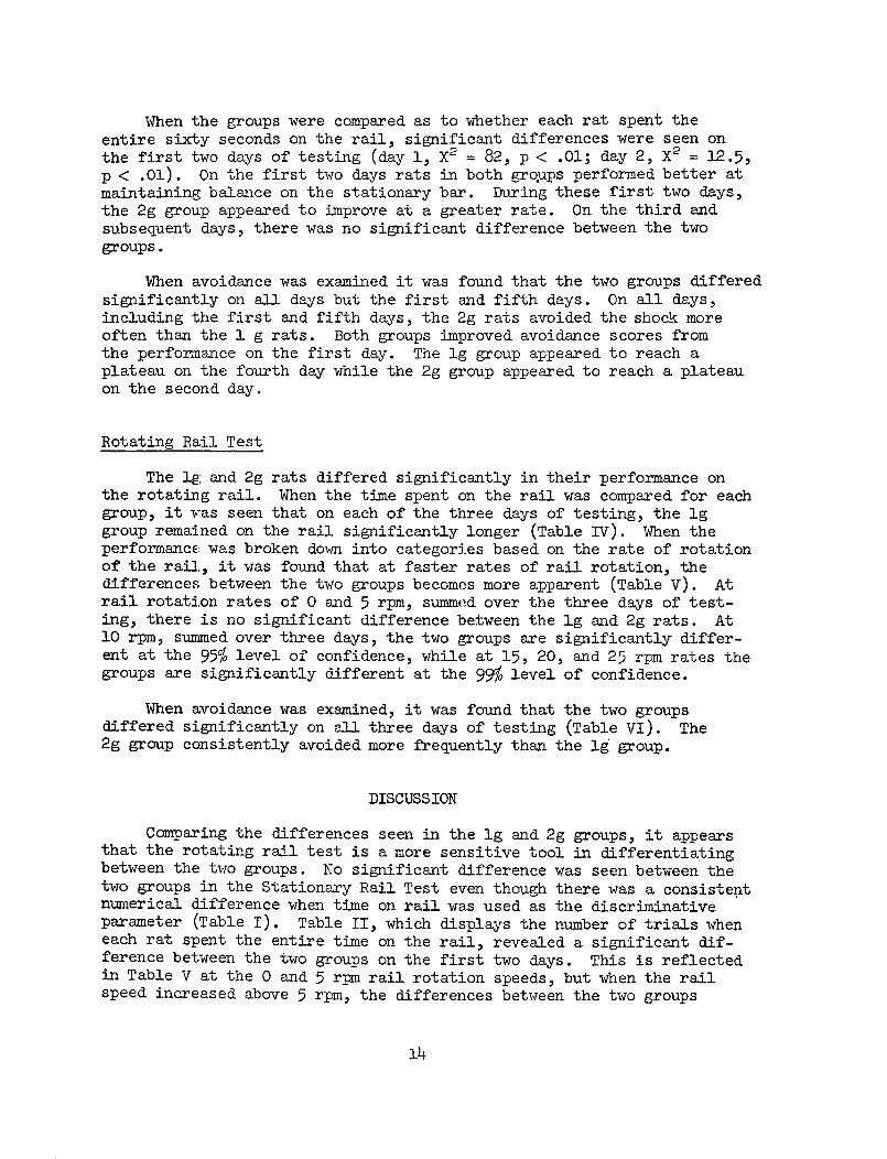
When the groups were compared as to whether each rat spent theentire sixty seconds on the rail, significant differences were seen onthe first two days of testing (day 1, X2 = 82, p < .01; day 2, X2 = 12.5,p < .01). On the first two days rats in both groups performed better atmaintaining balance on the stationary bar. During these first two days,the 2g group appeared to improve at a greater rate. On the third andsubsequent days, there was no significant difference between the twogroups.
When avoidance was examined it was found that the two groups differedsignificantly on all days but the first and fifth days. On all days,including the first and fifth days, the 2g rats avoided the shock moreoften than the 1 g rats. Both groups improved avoidance scores fromthe performance on the first day. The lg group appeared to reach aplateau on the fourth day while the 2g group appeared to reach a plateauon the second day.
Rotating Rail Test
The lg and 2g rats differed significantly in their performance onthe rotating rail. When the time spent on the rail was compared for eachgroup, it was seen that on each of the three days of testing, the lggroup remained on the rail significantly longer (Table IV). When theperformance was broken down into categories based on the rate of rotationof the rail, it was found that at faster rates of rail rotation, thedifferences between the two groups becomes more apparent (Table V). Atrail rotation rates of 0 and 5 rpm, summed over the three days of test-ing, there is no significant difference between the lg and 2g rats. At10 rpm, summed over three days, the two groups are significantly differ-ent at the 95% level of confidence, while at 15, 20, and 25 rpm rates thegroups are significantly different at the 99% level of confidence.
When avoidance was examined, it was found that the two groupsdiffered significantly on all three days of testing (Table VI). The2g group consistently avoided more frequently than the lg group.
DISCUSSION
Comparing the differences seen in the lg and 2g groups, it appearsthat the rotating rail test is a more sensitive tool in differentiatingbetween the two groups. No significant difference was seen between thetwo groups in the Stationary Rail Test even though there was a consistentnumerical difference when time on rail was used as the discriminativeparameter (Table I). Table II, which displays the number of trials wheneach rat spent the entire time on the rail, revealed a significant dif-ference between the two groups on the first two days. This is reflectedin Table V at the 0 and 5 rpm rail rotation speeds, but when the railspeed increased above 5 rpm, the differences between the two groups
14
becomes more apparent. At the higher rail rotation speeds the differencesbetween the two groups appears to be progressively greater as suggestedby the increasing "+" values (Table V). This difference may be moresignificant at rail rotation speeds above 25 rpm.
The lg and 2g rats differed in their ability to balance. This wasconsistently obvious to the experimenter, even in the stationary railtest. The 2g rats appeared to have much difficulty in maintainingthemselves on the rail. They appeared to "lose their balance" oftenbut soon learned to stay on the rail even though they appeared to havemuch more difficulty than the lg animals. These subjective evaluationson my part were not reflected in the scores seen in the Stationary RailTest. At higher rail rotation speeds in the Rotating Rail Test, however,these differences began to become apparent in the test scores.
The data measuring time on rail, for the first three days in theStationary Rail Test revealed a consistent, but not significantly dif-ferent, difference between the lg and 2g rats (Table I). Similardifferences were seen for the first five days when the two groups werecompared as to the average number of trials in which each rat spent theentire time on the rail. The data were significantly different for thefirst two days (Table II). The Rotating Rail Test revealed that thetwo groups did not differ at 0 and 5 rpm. But when the test becamemore demanding, i.e., at higher rail rotation speeds, the differencesbetween the two groups became significant.
The deta from both tests reveal that both the lg rats and 2g ratsimproved their ability to stay on the rail with experience. This isespecially apparent when the scores are compared in the Stationary RailTest which ran for a longer time period. If the "+" values are comparedin Table IV, it appears that both groups are improving performance atabout the same rate. There is no reason, based on these data, to suggestthat the 2g rats will approach the lg rats in their balancing ability.This raises two questions. First, given enough training (e.g., severalweeks) will the 2g rats approach the performance level of the lg rats?Second, if the 2g rats were to remain in the lg environment, would theyeventually approach the performance of the lg rats? How long would thistake?
It is premature at this time to speculate on the anatomical and/orphysiological basis for the behavioral differences seen. The data mightsuggest that it is a system that is called upon to function more in adynamic situation (viz., semicircular canals). This may be the case.However, even when balancing on the stationary rail, the 2g rat experi-ences more difficulty in maintaining balance, implying that other sen-sory mechanisms may be involved.
The differences seen in avoidance behavior were unexpected. The2g group avoided consistently more frequently than did the lg group.Both groups improved their avoidance scores with experience (Table III).
15

The X2 values remained high even at the end of ten days of testing,suggesting that the difference between the two groups was remainingconstant. The cause for these differences is unknown. We mightspeculate that the 2g environment has imposed a stress factor that hasaltered the arousal level in the 2g rats. Possibly the answer may liewith the reported vestibular fibers projecting to the brain stem re-ticular formation, and the known influence of vestibular stimulation onvisceral efferents.
16

Table 1 - Stationary Rail Test. (lg rats and 2g rats compared as toaverage time, in seconds, spent on rail during one 60 secondtrial. Ten rats per group were exposed to ten trials eachday for ten days. The groups are not significantly differentfor any day).
DayGroup 1 2 3 4 5 6 7 8 9 10
lg 49.0 52.2 60.0 60.0 60.0 60.0 6O. 60. 0 60.0 60.0 60.0
2g 38.0 47.3 56.3 60.0 60.0 60.0 60.0 60.0 60.0 60.0
t value 1.46 0.62 4.68
Table 2 - Stationary Rail Test. (lg rats and 2g rats compared as toaverage number of trials in which each rat spent entiretime on rail. Ten rats per group were exposed to tentrials each day for ten days).
s~~~~~~~~~~~~~~~~~~~~~~~~~~~~~~~~~~~~~~~~~~~~~~~~~~~~~~~~
Day
Group 1 2 3 4 5 6 7 8 9 10
lg 8.2 9.0 9.6 10.0 10.0 10.0 10.0 10.0 10.0 10.0
2g 1.8 7.0 9.8 9.8 9.8 10.0 10.0 10.0 10.0 10.0
x 2 82.0o** 12.5** 0.57
Table 3- Stationary Rail Test. (lg rats and 2g rats compared asto avoidance responses made each day. Ten rats pergroup were exposed to ten trials per day for ten days).
Day
Group 1 2 3 4 5 6 7 8 9 10
lg .2 .2 .6 3.4 1.8 2.2 2.6 1.6 2.4 2.8
2g .6 3.6 4.8 5.2 2.8 4.6 5.4 4.6 4.4 5.0
X2 2.1** 37.4** 44.8** 6.6* 2.8 12.8** 16.1** 21.2** 8.8** 10.2**
17

Table 4 - Rotating Rail Test. (lg rats and 2g rats compared as toaverage time, in seconds, spent on rail during one 60second trial. Ten rats per group were exposed to tentrials each day for three days. Data are averaged forrail speed from zero to 25 rpm).
DayGroup 1 2 3roup 1 2 3
lg
2g
t value
45.2
30.5
3.49*
48.6
36.5
3.75*
52.7
35.6
3.38*
Table 5 - Rotating Rail Test. (lg rats and 2g rats compared as toaverage time, in seconds, spent on rail during one 60second trial. Ten rats per group were exposed to tentrials each day for three days. Data are averaged forthree days).
Rail Speed (rpm)Group 0 5 10 15 20 25
lg 58.o 54.1 50.9 48.9 40.9 39.2
2g 57.1 47.8 35.1 29.9 22.3 19.8
t value 0.31 1.33 2.48-*- 3.52* 3.03* 3.62*
Table 6 - Rotating Rail Test. (lg and 2g rats compared as toaverage number of avoidance responses made each day.Ten rats per group were exposed to ten trials perday for three days).
DayGroup 1 2 3
lg 2.2 2.0 2.8
2g 5.0 3.5 3.2
X2 27.24* 7.56* 6.54*
* significantly different at the** significantly different at the
0.05 level( This reference applies to0.01 level Tables II through VI.
18

PART III
INTRODUCTION
PHYSIOLOGICAL REVIEW AND MATHEMATICAL BASIS
1. Vestibular Apparatus
The membranous labyrinth is located in the inner ear. It con-sists of the cochlear duct, three semicircular canals, and two relativelylarge sacs known as the utricle and the saccule. The cochlear duct isconcerned with hearing and has nothing to do with equilibrium; the roleof saccule in orientation and postural control is not clearly understoodin higher animals. However, the utricle and the semicircular canals areimportant for maintaining equilibrium.
a. Utricle--The macula is the sensory epithelium of theutricle and consists of sensory cells, a gelatinous substance and manysmall calcium carbonate crystals called otoliths. The otoliths are moredense than the surrounding structures and fluid and, thus, are differ-entially attracted by gravity. The otoliths are embedded in the uppersurface of the gelatinous substance; below the gelatinous substance arelocated many sensory hair cells. Two types of sensory cells have beenidentified and are referred to as Type I and Type II. Small sensorycilia project from the sensory cells into the gelatinous substance.It is presumed that a shifting of the otoliths results in a shearingaction imparted to the cilia of the sensory cells which action resultsin depolarization of the sensory cell.
b. Semicircular Canals--The three semicircular canals, knownas the anterior, posterior, and horizontal (or lateral) semicircularcanals, are arranged at approximately right angles to each other, sothat they roughly form an orthogonal system. The lateral canals liein a plane tilted approximately 30 degrees above the horizontal. Thetwo vertical canals lie approximately vertical to the plane of thehorizontal canal and 90 degrees to each other.
Each canal is in communication with the cavity of the utricle.At one end of each canal the duct dilates into an enlarged cavity, theampulla. The neurosensory epithelium of each semicircular canal lieswithin the ampulla.
The neurosensory structure in the ampulla is called the cristaampullaris. The crista is composed of an overlying gelatinous cupulaand sensory hair cells below. The cupula occludes the ampulla. Ciliaproject from the sensory hair cells into the cupula. The cilia in eachcrista ampullaris are uniformly directionally oriented.
19

When the head is rotated in any direction, the endolymph in thesemicircular canals tends to remain stationary due to inertia. Theinertia force causes deflection of the cupula. Deflection of thecupula results in a shearing force transmitted to the cilia of thesensory cells. This action results in depolarization or hyperpolari-zation of the cell, depending upon the direction of cupular deflection.The appropriate neural signals are transmitted via the eighth cranialnerve to the brainstem, cause a sensation of rotation and induce thecompensatory eye movement called nystagmus.
c. Nystagmus--Nystagmus is the reflex eye movement due to adeflection of the cupula. When the head is accelerated about an axisprojected vertically through the center of the head, the eyes moveslowly in a direction opposite to the direction of rotation with avelocity equal to that with which the head is turning. This is theslow phase of nystagmus. This movement tends to fixate a visual imageon the retina, and minimize the displacement of the image on the retina.The rapid return of the eye to a new starting point in the orbit iscalled the fast phase of nystagmus.
2. System Analysis
In the field of control systems analysis, one of the mostimportant things is to identify the transfer-function of the system,which gives information about the functional organization of the mecha-nism. From the point of view of system analysis, we are dealing witha very complicated system which has probably a number of feedback loopsin the central nervous system and cross-couples with other systems(i.e., otoliths) through the C.N.S. But, on a biological basis it isnot possible to determine the open-loop transfer functions in greatdetail. We can develop an over-all model of the system which explainsbehavioral "input-output" data and is consistent with known physiolog-ical structures.
a. System Transfer Function--The simplified horizontal vesti-bulo-ocular reflex arc is shown in Fig. l(a). For convenience inanalysis, the system can be grouped and arranged in several block dia-grams which is summarized in Fig. 1 (b). This system has multivariableinputs and a single output, but for easy manipulation we have to re-strict attention to one input and one output which is shown in Fig. 1(c). The relation between input and output is expressed by the transferH(s) in the complex frequency domain:
H(s) = V(1)
20
or-( v
0~0rd
Cd ~ ~ ~ ~ ~
O -Po Crl P
0 Cd CH r-
,D
*. rdl0 0
0~~~~~~
£~~~~~~I o 0
r 01 rlH 0'-'
Qa -4- r
0~~~~~
0 0 ..
Id .rd Od
0
a)) r.l
Orjr-I --
o g
H q-
-· -p ..I
.r CO -
r,~~~~4 S Y H
0 .4
.d-
o - or*Ho-*rl*Fh2 0
t<U D] V}~~4141~~
Q < = = =HEIE-
'4 E4n E4
H>__
21
4)
"A
0.r4
41·- (LCao C
Cv
*r
Id~ hC)
rq r

where
~(s) = Laplace transform of the input angular acceleration, and
V(s) = Laplace transform of the velocity of slow-phase nystagmus.
Since the time function of the velocity of slow-phase nystagmusfollowing an impulse input has the form of an exponential decay, thesystem transfer function H(s) can be assumed to be:
bn_ sn-1 + b n-2 + ... + b2s2 + b s + bH(s) n-1 n-+ 2 1
H (s + 1/al)(s + 1/a2 ).(s + 1/an) (2)
where al, a2 , '', an, bo, bl, b2 , , bn-2, bn-, are constants to bedetermined. Taking the partial fraction expansion of Eq. (2) gives
H(s) = +al +A2H(s) = A1+..An
s + /ans + 1/an
Then, let the input be an impulse function
(t) = 78(t)
(3)
(4)
where 5(t) is the unit impulse function and y is the magnitude of theimpulse. The corresponding Laplace transform funmction of (t) is
i(s) = 7. (5)
Substituting Eqs. (3) and (5) into Eq. (1), then
V(s) = ~(s)H(s)
+ 2 + .. + A/an )S + 1/a2 5 + la
The impulse response function is
v(t) = y(Ae-t/al + A2e-t/a2 + ... + Ane-t/an)
22
(6)
(7)
= 7 a ~

The impulse stimulus gives rise to an after-discharge of nystagmuscalled post-rotatory nystagmus which is the impulse response. Theactual electrical recording of the ocular nystagmus is shown in Fig. 2(a) which indicates the position of the eye. Figure 2 (b) gives thedifferentiation of the trace. The upper part of (a) shows the slow-phase velocity which follows an exponential decay with respect to time.The slow-phase velocity does not decay to zero, it ceases at certainthreshold level vmin. The time between the onset of input stimulus andthe cessation of nystagmus is called post-rotatory nystagmus.
Vmin = y(Ale-TP/al + A2e-Tp/a2 + ... + Ane-Tp/an)
1 A1 e-Tp/ai + A2 e-Tp/a2 + ... + An e-Tp/an 8)7 Vrmin Vmin vmin
where
Tp = duration of post-rotatory nystagmus, and
Vmin = the minimum slow-phase eye velocity at theend of nystagmus.
If the values of y are varied and then the values of 1/7 areplotted in logarithmic scale vs. each corresponding Tp, the time con-stant of each exponent can be extracted from the curve, provided theyare adequately separated. Practically, the input stimulations arepulses. It is shown (see Appendix) that the same time constants occurwhether or not the input is an impulse or a pulse of finite width.
b. Dynamic Characteristics of the Semicircular Canals
(i) Transfer function of the canal--Although overalltransfer function discovery is very important in system analysis,identifying each single physical component of the system would givemore details about the system dynamics. Fortunately, based on itsphysical structures and characteristics, the mechanics of the semi-circular canal can be described by a simple second-order differentialequation.
As early as 1931, Steinhausen pointed out that the moment ofinertia of the endolymph, the stiffness of the cupula and the viscousfriction of the fluid in the canal provide this system with the proper-ties of a heavily damped torsion pendulum. In the idealized perfectlycircular form of a canal (Fig. 3), the fluid ring can be considered torotate around the center of the canal. Therefore, Newton's second lawstates the system dynamics as
23
.-._:-:'i ': . : .;: ;:- :.-:'-i.-:1- f" / / l i i-': i,- i t' -, ~=-'t ': .' ":i'"Ft -~"-1 ' :'
? -'-:- ...... t- "' .- :-' L::_ :::L:-1-j:--- .1.--.:: 1-.'. [. :£--"! L-Lji-T ',: .:>: E-:_-- .. '_.
I'!I~..~4: ____'
I- ''~~~~~~~~~~~~~~~~~~~~~~~~~~~~~~~I:-
7- 7 t =
1 --.: -- -: .t ..,._, ·j j,_t= i -. \............ ..... ; ...... ... - -. : .... ,.. - '"-".; i, :,, .............I .... .A... .
,=If..,......... . -"- I . ~ ' , .. i .. / ' - ' . / I , , ., / " . .......... ,.... .....
I- EilE k :9\7iif+7 _~ -. \ ,_ _... _ . _ _ !
;-=:-~u~j-= 1-~:-: -I ':-. - ::: r:'' : ... ,- - .'- - I ~- ,._- _}-- =].~ =:{-. :I::- 'i-=1----,.--~--__j=:_.:'
I, .._ _....., .....,. .,.j.i.,,. ..................... ~......... . , ._,__ .,.,..... ,..... ~................... ...... .z _ ,._~ .......... ~....... . . . ............ , -- ---
i- +t --- -- -; . - [ -;--: .i- | r -;-- _ = ._:
..... _ _ _ . , .......... ......... . : , .............. : .- ~ : , ......
" -- , - f.l .. ,~, , . .;- .... i .--- .... ~ .,... . o..,.. ~ _-- -- . . .__.. _ -.-'--._-.-
: _X-;-.,-t: :£_ I, , ...................... _ .......\-\- . -\_\ .........'....,..........................,- _~~~~~~~~~~" ' ' t'~ u ......... ·'~ - . . ~..., ....
i ___-- ---. :' -_.-'--11" .> --'- -:- -= ._ -- !--i=i- .-- -. .... . .....i.i: . , _-:I._ _ _ ... §._
.t_. I ... ., 7.
,I-! I -j.-i- _E -,..t '-:tZ.- --- -t---1 -_ -- , _ -- 1-- ----- --- I-'-FED I=-Xt -- i--tL.---.t
I--l- ~ ~ ~ ~ ~ rr I-I ' 1 - - - - -l.. .. I
.- j
.....
...............
.: = =-'----' ... *-- .i-- 1 ....... ..__ -_ -I -- - -..........- . . ..I---:i-~-~ : - --- ~ ,-L=::~ ! =I _ I-_ I_ _ :;-~=: = _ =-- --- ---- =- = == >
. _..... .. ... _.,... . ,_.,_I........ '....... ~-........ ... =: _ .... _ .... ' ... , ...... ',- .... I-._-_;-__.-_].\ ,\-! .- --,\ ..-. -! ... __. 73_.::!:_~ _ __: :::_ ,=< l- = :,_-..-,_--t :::-- j-_.:~-_ ~~~~,~ · · , . .... , , ...... , . _. . _ . _ _:, _ . ...
Fig 2 Recording of post-rotatory ocular nystagmus indicating theposition of the eye (a); the differentiation of the trace (b);and the inverse of velocity of the turntable (c).
24
j -~-.r~- ~-,- =! 1_-s-=-I.-~i-' -f~--_---~__/::£F!:.?-_r--- z=:r-t-_-t~: -- :F_-. =-_-.7f_----,_-_ 1-- . ..... I . I -- t- - , I . ! ....

.Y Head
Canal
Relative=(YV-OG)a
U lr i c Ier
I II /
I I/ /
Ampulla
3 daz f otehinl se
Fig. 3 Idealized form of' the horizontal semicircular canaEl.
25

ni($ - ~) + M(C - *) -= 8 (9)
where
8 = moment of inertia of the fluid in the canal,
H = viscous friction at unit angular velocity, and
A = stiffness of the cupula at unit angular displacement
Although Eq. (9) provides the correct absolute space relations, we areinterested in the relative angular displacement t which causes theneural output. Thus, we define k as cupula deflection per unit relativeangular displacement between head and fluid, and
t = k(q - *) (10)
Substituting Eq. (10) into Eq. (9)
ae + li + At = kG* (11)
This is the linear second-order differential equation for the endolymph-cupula system. The corresponding transfer function of Eq. (11) is
s (s) ks= s + (/9)s + (A/8e)
(12)
A second-order equation can be considered as made up of two cascadedfirst-order lags, i.e.,
S(s) s+ kms= (s + /T)(s + l/T2 ) (13)
Comparison of Eqs. (12) and (13) yields
T1 T2 = 8/A T1 + T2 = H/A (14)
In the case of a highly overdamped system, it turns out T1 >> T2.Solving Eq. (14)
26

T, = I/L T2 G /I (15)
Substituting Eq. (15) into Eq. (13) gives
at (s + kI)(s + /) (16)
(ii) Impulse response--The constants in Eq. (16) must bedetermined in order to predict any conduct of the cupula found inpractice. One way to solve this problem is to use a series of impulsestimuli with different magnitudes. The constants can be found byanalyzing the output response. Substituting Eq. (5) into Eq. (16)
(s) (s +17z~ (s) +A ( s + II/)(s + /e) (17)
By taking partial fraction of Eq. (17) and using I/@ >> t/T gives
s s) ky 2 - ) (18)
The corresponding response function is
~(t) = k( (e -e t) (19)
Eq. (19) can be approximated further
At - At
-ky e T (20)
which points to a strictly exponential decay of t with time. It isbelieved that cupula displacement regulates the rate of discharge ofthe sensory cells and amnpullary nerves. In turn, the neural firingrate is known to regulate the magnitude of responses such as nystagmus.Therefore, it is reasonable to use theoretical cupula displacementduring semicircular canal stimulation as an approximate predictor ofnystagmus. Then, by taking logarithm on both sides of Eq. (20), thenystagmus expires after Tp sec,
27

H / k7E
Tp = loge(H ) (21)
= I lge + loge kmin (22)
where ~min denotes the smallest deviation of the cupula giving rise toa just noticeable nystagmus and Tp is called the duration of post-rotatory nystagmus.
The duration Tp can be plotted in a diagram called "cupulogram"which was originally developed by Van Egmond, Groen, and Jongkees. Thesteepness of the nystagmus cupulogram should give the value of I/A.
(iii) Pulse response--Theoretically, an impulse ofacceleration requires instantaneous stopping of the skull. The term"impulse" here means that the braking time should be infinitesmal. Thiscan not be achieved practically even using an electromagnetic brake.But usually a short pulse with duration less than one-tenth of the re-sponse time is considered as an "impulse". When the pulse width cannot be further reduced to meet the one-tenth requirement, due to thelimitations of the instrument, the "impulse" will become impractical.One way to avoid the difficulty in this time constant discovery problemis to let the width of all pulses be the same.
An angular acceleration pulse with duration ¶ and magnitude a isshown in Fig. 4 (a).
@(t) = a[u(t) - u(t - r)] (23)
where
u(t - T) = 1 when (t - T) > O
= 0O when (t - T) < O
By taking Laplace transform of Eq. (23)
¢(s) = t1 n Eq) (24)
Substituting Eq. (24) into (16)
28

(t)
a0
(a)
, i ~~~~~~~I
~min _
0T Tp
(b)
Fig. 4 (a) The angular acceleration pulse i(t) = a[u(t) - u(t - )](b) the pulse response t(t) with min and Tp.
29
gs) = kc(l - e )s(s + A/1)(s + /e)(s ( +'~/I) s H ]~
Taking the partial fraction expansion of Eq. (25) and approximating itby T/e >> t/i1
m(s) = kMa (1 - e- r
s 1 - e¶S)s + /IT
(26)
The corresponding pulse response function Fig. 4 (b) is
~(t) = ka A (1 - e )u(t)
( cr8 ( t1-))- 1 u(t-[-ka D( - eif ut (27)
Let t = Tp, (Tp) = ~min, and Tp > T. Equation (27)as
= min - -= k I6min = a e tenA
- 1)
can be simplified
(28)
The relation between Tp and a is
Tp = A logea + A loge k- + A loge(eA A Z~-i / A
- 1) (29)
This equation, except for I loge(ee - 1) appearing on the right hand
side, is equivalent to Eq. (22). If T, the width of the pulse, is keptconstant, E/A should be given by plotting the cupulogram.
Even the T's areEq. (29) can still bean iteration process.
not the same for all different magnitude pulses,modified to given the time constant, E/A, throughLet
C = loge(e T -1) - t (30)
3o
(25)

Equation (29) becomes-
(Tp - ) - C = l + loge+ oge (31)
Thus, a predictor-corrector method which is often used in numericalanalysis to solve a differential equation can be similarly applied hereto find the value of I/A. Let
predictor: Tp- ¶ = logea + A loge(kO) (31a)A ~~A mi
A '
corrector: C = loge(e - 1 - (30)
(Tp - ¶) - C = _ lo + gea + loge( (31)A A \Aimin/
Equation (31a) provides the starting value of /A by graphical method(cupulogram); we then evaluate a set of C's from Eq. (30) and substitutein Eq. (31) to generate a new value of t/A graphically. Next we evaluatea new set of C's based on the new I/A and again use Eq. (31) to obtaina next I/A. This iteration process is terminated when two successiveiterates agree to the desired accuracy.
(iv) Step response--The vestibular model can also betested by using steps of constant acceleration and observing the latencybetween the onset of constant angular acceleration and the beginning ofthe nystagmus, Fig. 2 (b). The latency may be attributed to the factthat a threshold nonlinearity exists in the eye dynamics or in the C.N.S.
The step response can be obtained by letting T approach infinityin Eq. (27), therefore
t(t) =ka (1 - e E )u(t) (32)
since
lim u(t - O) = 0T o00
31

Assume ~th is the corresponding threshold deviation of the cupulaand TL is the latency of nystagmus,
fth = kae (1- e HL)
If a reaches oth which is the constant angular acceleration re-quired to produce a threshold deviation, the latency time, TL, willapproach infinity. Thus,
tcit= kAth(34)
Substitute Eth in Eq. (33) by
-=h1 e L(35)a
The threshold acceleration Uth can be given by having Eq. (35) bestfit the experimental data, provided H/A is known.
(v) Theoretical value of 8, H and A--When the anatomicaldata concerning the semicircular canal are known, the constants of thefundamental differential equation, Eq. (11), of the cupula-endolymphsystem may be calculated on the basis of fluid dynamics.
The moment of inertia 8 is evaluated on the assumption that theendolymph ring keeps the same cross section even in the utricle. Thatis, the canal extends itself through the utricle, contributing to themoment of inertia but not to the friction. Then, e (from Van Egmond)is expressed as
e - 2n2 or 2R3 (36)
where
- = density of the endolymph,
r = cross-section radius of the canal, and
R = radius of curvature of the canal.
32

The viscous friction H is given by
A = 8iR 2 L
where
= viscosity of endolymph, and
L = length of canal.
The mean canal length of the rat, 1.28 iR, is approximately two-thirdsof its circumference. By substituting L = 1.28 AR into Eq. (37)
I = 10.24 A2 1R3 (38)
The stiffness of the cupula A is given by
A = iir R (39)
where p is the coefficient of elasticity.
Therefore, dividing II and a by A and H, respectively, gives thevalue of two time constants Eq. (15)
T, _ 10.24 AnR2
= A 4r2
T2 = - 5.1211 5-12 il
(4o)
(41)
RESULTS
TIME CONSTANTS OF THE SYSTEM
The duration of post-rotatory nystagmus for each pulse input isdetermined. Tables 1 and 2 list the means and standard deviations ofduration for lg and 2g rats, respectively.
33
(37)

Table 1 The means and standard deviations of durationof post-rotatory nystagmus for lg rats
DECELERATION DURATION OF POST-ROTATORY NYSTAGMUS (sec)RATE
(°/sec2 ) MEAN STANDARD DEVIATION
20 4.03 0.73
25 4.06 0.72
30 3.41 0.53
40 4.34 1.11
50 4.84 1.02
60 4.46 0.97
80 6.16 1.25
100 6.36 2.09
125 7.80 3.51
150 9.0% 2.40
200 11.50 3.26
250 14.32 3.37
300 15.12 2.82
Table 2 The means and standard deviations of durationof post-rotatory nystagmus for 2g rats
DECELERATION DURATION OF POST-ROTATORY NYSTAGMUS (sec)RATE
(O/sec2 ) MEAN STANDARD DEVIATION
50 3.77 0.57
60 3.85 1.09
80 3.92 0.68
100 4.31 0.65
125 5.00 1.07
150 5.04 1.14
200 6.68 1.36
250 8.71 2.06
300 10.09 1.40
34

The durations as a function of the inverse of deceleration rateare plotted in Fig. 5 (lg) and Fig. 6 (2g), which are essentially thesame as cupulograms. The solid curves are chosen to best-fit the data.If the vestibular system could be simply described by a second-orderequation (Eq. 11), the cupulogram corresponding to it should reveal astraight line response (Eq. 22). However, since the response in Fig. 5is considered as a second-order curve by regression analysis, it sug-gests that the overall response includes more than one exponential term(Eq. 8 and A-9).
A logarithmic ordinate is chosen so that any single exponentialdecay should be revealed as a straight line. Although the curve inFig. 5 is curved initially, it does eventually tend to a straight line,suggesting that this part of the response can be approximated by theslowest exponential term, because all faster exponentials have decayedto zero by this time. The slope of this straight portion gives thecorresponding time constant. The straight part is then subtracted fromthe over-all response curve. The new curve is superimposed on Fig. 5.Again, as Tp increases, a single exponential is present with a shortertime constant. After a further repetition, a straight line is obtained,so that the process ends. The same technique is then applied in Fig. 6.Table 3 summarizes the time constants from the response curves of lgand 2g rats.
A different set of deceleration rates with varying pulse widthswere used to test lg rats. The corresponding results are summarizedin Table 4. A method called the predictor-corrector method, which isdescribed by Eqs. (30), (31), and (31a), can be applied to evaluate theH value of H/A. Figure 7 shows the procedures of the method and indi-cates the resulting II/A (9.1 sec., approximately).
Using Eq. (41), 8/H = 0r2/5.12 i, with a = 1.0087 g/cm3 , ~ = 0.0115g/cm and y = 0.0091 cm, gives us another time constant, T2 = 1.42 x 10- 3
sec, of the semicircular canal. Since this value is too small, none ofthe suggested methods which were described previously can reveal it.The time constants of the semicircular canal can be summarized asT1 = I/A = 9.1 sec and T2 = 8/[ = 1.42 x 10- 3 sec.
INPUT THRESHOLD LEVEL OF THE SYSTEM
The mean latency of nystagmus corresponding to each input deceler-ation is listed in Tables 5 and 6 for lg and 2g-rats, respectively.
The latencies, as a function of deceleration, are shown in Figs. 8and 9. By using Eq. (35) with known I/A = 9.05 for lg rats and I/A = 8.42for the 2g rats, the value can be adjusted until the equation fits theexperimental data. The solid curve in Fig. 8 gives ot = 5°/sec2 for1G rats and the one in Fig. 9 shows a higher input threshold level(11°/sec2 ) for the 2g rats.
35

8.410'- - \v
z~ -UO. - - % - .
--
6"2104- ) a,'
4,10-.L
z8X0 % \\
a3
- 2610- ' \UWO
w I Il
40 6.0 80 10.0 12.0 14.0DIRATION IN SECONDS
4.s1o':
II i I II I IiI II4.0 6.0 80 10.0 12.0 1.4.0
DURATION IN SECONDS
Fig. 5 Mean duration as a function of inverse decelerationrate for six lg rats. The slopes of the three straightlines give the time constants of the system: 9.05,1.30, and 0.39.
36

2,,1d--\ \
U3 -
z6,~o-'\ ;-eX105-_
z 6-10 3 h a,~
a4X10- a3 \n - 4.(L ' '
4,,,10-
MW ' 1¢ % ..
;$ 6,'1C¢-
z
-H~~~~~~~~~~
4x'104
I I '' i i I I i' i i l 4.0 6.0 8.0 10.0 12.0
DURATION IN SECONDS
Fig. 6 Mean duration as a fumction of inverse deceleration ratefor eight 2g rats. The missing time constant of 1.30shows the difference betweenl g and 2g rats.
.37

Table 3 The time constants of lg and 2g rats
TIME CONSTANT (sec)
a1 a2 a3
1G 9.05 1.30 0.39
2G 8.41 0.30
Table 4 Mean duration of post-rotatorynystagmus (Tp) for lg rats
DECELER\TION DECELERATION MEAN DURATION OF
PRATE TIMT POST-ROTATORY NYSTAGMUS
(o/scc2 ) (sec) (sec)
T Tp Tp -
30 20.0 21.43 1.43
40 15.0 17.78 2.78
50 12.0 15.91 3.91
60 10.0 15.50 5.50
80 7.5 14.09 6.59
100 6.0 13.71 7.71
125 4.8 13.09 8.29
150 4.0 13.05 9.05
130 3.33 13.01 9.68
210 2.86 12.67 9.81
38

14.0-
120
10.0-
00 zUOui8.0
z
z
~60-
0
4.0-
.2.0-
I i I I I I l II 30 40 60 80 100 200RATE OF DECELERATION IN O/SEC 2
Fig. 7 A predictor-corrector method indicates thevalue of H/A, 9.1, approximately.
39

Table 5 The mean and standard deviation of latencyof nystagmus for lg rats
DECELERATION RATE lATENCY OF NYSTAGMUS (sec)
(o/sec2 ) MF\N STANDARD DEVIATION
20 2.96 2.16
25 1.20 0.35
30 1.39 0.64
40 1.00 0.43
50 0.75 0.14
60 0.77 0.33
80 0.63 0.25
100 0.56 0.21
125 0.40 0.09
150 0.37 0.11
200 0.27 0.06
250 0.25 0.06
300 0.21 0.08
4o

Table 6 The mean and standard deviation of latencyof nystagmus for 2g rats
DECELERATION RATE
(°/sec2)
20
30
40
50
60
80
100
125
150
200
250
300
IATENCY OF NYSTAGNUS (sec)
MEAN STANDARD DEVIATION
12.82
2.90
2.72
1.35
1.64
1.20
0.98
0.95
0.80
0.56
0.41
0.39
5.93
1.36
1.58
0.17
0.62
0.50
0.38
0.36
0.31
0.16
0.17
0.15

.
a
I I-60
-I I120
l-I180
I I240
NATE OF DECELERATION IN °/SEC2
Fig. 8 The latency of nystagmus following the onsetof constant angular deceleration for lg rats.The threshold deceleration is 5°/sec2 .
42
4.0-
0
z0U
w11)
z
UzLdJ
I
3.0-
2.0-
1.0-
I I300
12 0120 1 80180I I I !
240 300
RATE OF DECELERATION IN o,'SEC2
The latency of nystagmus for 2g rats. Thethreshold deceleration indicates a higherthreshold level of 11°/sec2 .
43
4.0-
Z0
)-
z0uw
LLz
uzw-
_J
3.0-
20-
1.0-
.
$
.
6060
Fig. -9

DISCUSSION AND CONCLUSION
One of the primary purposes of this study is to evaluate pulsewave forms of angular decelerations and the response they elicit as ameans of discovering the time constants of system in vestibular nystagmusresponse. Pulse waveforms were selected as a test stimuli because theyeliminated the difficulties due to the limitations of the stimulatorand provided an adequate method to test the rats.
However, the main goal is to find the response difference betweenrats chronically exposed to a lg and 2g environment on a basis ofbiocybernetic models of the horizontal vestibulo-ocular reflex arc.Before presenting the models, the time constants in Table 3 shouldfirst be related to the physical model.
Deceleration rates with varying pulse width were selected asstimuli. The advantage of using longer widths for low decelerationrates (Table 4) is to minimize the effect of exponential terms withshorter time constants on the overall response. Therefore, the systemtends to respond as a first-order system under these special stimula-tions. Although the cupulogram (Fig. 7) showed a straight line response,corrections are still needed to evaluate the actual value of H/A.
The value of H/A, 9.1 sec, is close to both al's. We can assume a1is attributed by the semicircular canal. I/A is determined by thecanal's physical dimensions Eq. (40) which are not changed duringchronic centrifugation. Assume the physical properties of canal, p, 1and a, are not changed. The value of H/A in either state should beequal to each other. Again the values of a1 shows the validity of thisassumption.
Comparing the time constants in Table 4 with the block diagrams inFig. 6 (a) leads to two assumptions. First, as may be related to eyedynamics which is not affected by the chronic 2g state. Ten Kate sug-gested a value between 0.25 and 3.97 sec for the time constant of pike'seye dynamics and a value of 0.32 sec for the cat. This may furthersupport the hypothesis.
a2 may be contributed by the utriculus via the C.N.S. Since linearacceleration influences the responses of the semicircular canals, aprolonged 2g state may interfere in some way with the vestibular re-sponse. The resulting effect could be the reason for the missing a2in the response of 2g rats.
The forces produced by gravitation, linear acceleration, and cen-trifugation are identical with respect to their effect on organisms.However, centrifugation differs from the other in that it involves arotation. The coriolis acceleration produced by body motions in arotating environment may habituate the nystagmus response and lead tothe absence of a2. This will need to be examined further.

The time constants of the semicircular canal were found as T1 = 9.1sec and T2 = 1.42 x 10- 3 sec. The inverse of T1 and T2 are correspondingto the lower and higher 3-dB frequencies of the canal in frequency domain.Therefore, the bandwidth, i.e., the range of frequency between higher andlower 3-dB frequency, is roughly from 0.11 rad/sec to 705 rad/sec. Maynestated the bandwidth of the canal appears to cover the range of bodymovement. Due to the small size and light weight of the rat, its band-width should include a range higher than that of a human being (from0.04 rad/sec to 300 rad/sec).
Summarizing the discussion and the results in the previous section,the mathematical models of lg and 2g for acceleration input are shownin Fig. 10. The value of 9 is chosen as a nominal value for the semi-circular canal. K1 , K2 and K3 are gains for each block. The model forcanal dynamics follows Eq. (12). The one suggested for eye dynamicsdescribes the damping of the eye muscles, however, To is only an assump-tion. Since the denominator is first order, a first-order term may ormay not exist in the numerator.
The threshold which only represents an over-all response of thesystem is not consistent with any physical structure in the horizontalvestibulo-ocular reflex arc.
Numerous investigators have suggested that the responses of thesemicircular canals may be described by a heavily over damped torsionpendulum. This means a nystagmus cupulogram should reveal a straightline response rather than a curve response which was shown in Figs. 6and 7. It appears that this assumption is too simple and that thedeviations from the presupposed mechanical laws point out either otherphysiological structures may play an important role in vestibularnystagmus response or the semicircular canal itself can not be approxi-mated by a simple linear second-order model. The semicircular canalstructure has its nonlinearities in the sense of mechanics. The springconstant of the cupula may not be constant even for small deviationsfrom the resting position; it may be a function of its own position.The damping factor is not linear in its nature and may be in quadraticform or have directional preference.
The difference between the responses of lg and 2g rats may also beexplained by the nonlinear characteristics of the semicircular canals.It is possible that chronic centrifugation may have an effect on thevestibular organs. Anatomical studies on rats exposed to chronicacceleration have shown considerable changes in body size and in tissuecomposition. These changes may result from the increased apparentdensity of body tissues and fluids induced by the greater accelerativeforce. Similarly induced changes in chemical composition of the laby-rinth may have resulted from chronic hypergravity. Therefore thedensity and viscosity of endolymph or the spring coefficient of thecupula may differ from those of lg rats. These differences, if theyexist, could alter the functional characteristics of the semicircularcanal.
45

oto la
to
ci
.q
I
a0
r.
54F4-
Z L3
H
Q co
.4 I
xa c'J
A~~~o
-.2~
0%
1r\ C°1l'
('J
AU U
0
044
0 F os 0r
O <4 o
0
orl
'- 0.,
0
CJ d
O
*,1d
CH
hi)
O N
O
0 )
H .qa)
E ~6
r-I E
Co dEcdi
b0
E 4
0)
bO.,,
46

APPENDIX
An angular acceleration pulse of duration T and magnitude a can beexpressed as
~(t) = CI[u(t) - u(t - T)] (A-1)
The corresponding Laplace transform is
¢(s) = 41 eTS] (A-2)
Substituting Eq. (A-2) in
V(s) = S(s)[ ( + /s + +b.-s + b1/an) (A-3)
L(S + 1 //a,)T(T T(s + 1a~
gives
V(s) = c(t - e-)[s( s + /al)(s + 1/')+ bAS +b ° ]
(A-4)
Take partial fraction of Eq. (A-4)
V(s) = a(l - eTs)( + + S~~1a +
+''+s + l/a2 s + 1/a
(A-5)
The corresponding impulse response function is
v(t) = aA o [u(t) - u(t - T)] + aA' [e-
t/a1 u(t) - e ( t-
)/a l u(t )]
+ aA [et/a2 u(t) - e(t-
n
)/a2 u(t- )] +
+ cAn [e-t/an u(t) e-(t-r)/an u(t - )] (A-6)
47

Let Tp be the duration of post-rotatory nystagmus and Vmin be theminimum slow-phase eye velocity. Then substitute Tp and vmin inEq. (A-6)
Vmin = aAo [u(Tp) - u(Tp - T)] + aAl [e Tp/al u(Tp) - e- (Tp - )/a l u(T -)
+ aA2 [e-
TP/al u(Tp)- e-(Tp-r)/a2 u(T -)
+ ... A[e Tp/an u(Tp) - e (Tp)/an u(Tp- )] (A-7)n~~~~~~~~
Since Tp > T, Eq. (A-7) becomes
Vmin= a[AI(l 1- e¶/al)e-Tp/al + A2(1 - eT/a2)e-TP/a2 + .
+ An(l - e/an)e T p / a ] (A-8)
Divide both sides of Eq. (A-8) by
1= Al (- er/a)e Tp/a1 + A (1 - e/a2)eP/a2 + -a vnm )e vmin
+ An (1 - eT/n)eTp/an (A-9)vmin
The relation between a and Tp is equivalent to that of y and Tp in
Eq. (8) except the constant terms (1- e,/al), (1 - ec/a2), ''',
(1 - e /a
n) existed in Eq. (A-9). Therefore, the same method can beapplied to find the time constants in pulse response.