the official publication of autodesk user group …6 autocad civil 3d express yourself: using...
TRANSCRIPT

www.augiworld.com US $8.00
January 2019
AUGIWorldT h e O f f i c i a l P u b l i c a t i o n o f A u t o d e s k U s e r G r o u p I n t e r n a t i o n a l
Diamond Sponsors
Advance Your Skills
Also in this issue:• Tips for Advanced 3ds Max Users
• Exploring Spaces in AutoCAD Architecture
• Using Expressions in Civil 3D

HP recommends Windows 10 Pro.
THE NEW Z WORKSTATIONSHP’s most powerful PCs
HP Z4HP’s bestselling performance workstationPerfect for advanced 3D CAD and BIM, the Z4 delivers mainstream performance for a range of applications. With a broad set of features, you get all you need, nothing more.
HP Z6A future-proof powerhouseNo matter what the future holds, you have the performance you need. The Z6 offers a range of processing power and the flexibility to expand components.
HP Z8The world’s most powerful workstation*From rendering to VR to machine learning, the Z8 with NVIDIA Quadro® graphics can enable companies to break through in every form.
* Based on workstations as of September 25, 2017 and power based on processor, graphics, memory, and power supply.
© 2018 HP Development Company, L.P. HP shall not be liable for technical or editorial errors or omissions contained herein. NVIDIA® is a registered trademark or trademark of NVIDIA® Corporation in the United States and/or other countries.
hp.com/go/Zdesktops

AUGIWorld JAN
UA
RY
2019
contentsproduct focus
12
January 2019 www.augi.com 3
4 Letter from the President
24 CAD Manager
31 Inside Track
6
columns
18
6 AutoCAD Civil 3D Express Yourself: Using Expressions in Civil 3D
10 InfraWorks A New Look at Familiar Features
12 Revit Structure Adding a Beam to a Beam Family
18 Revit Architecture Please, Don't (Just) Blame the Tech
22 3ds Max Advanced Tips for More Realistic Visualization
26 AutoCAD Architecture Exploring Spaces in ACA
22
The High Line, New York City, New York, USA Copyright © 2018 Tatjana Dzambazova
Letter from the President
4 www.augi.com January 2019
JAN
UA
RY
201
9
www.augiworld.com
EditorsEditor-in-ChiefDavid Harrington - [email protected]
Copy EditorMarilyn Law - [email protected]
Layout EditorDebby Gwaltney - [email protected]
Content Managers 3ds Max - Brian ChapmanAutoCAD - Jim FisherAutoCAD Architecture - Melinda HeavrinAutoCAD Civil 3D - Shawn HerringAutoCAD MEP - William CampbellBIM Construction - Kenny EastmanCAD Manager - Mark KikerInside Track - Brian AndresenInventorRevit Architecture - Jay ZallanRevit MEP - Nathan MulderRevit Structure -Jason Lush
Advertising / Reprint SalesKevin Merritt - [email protected]
AUGI Executive Team President Kimberly Fuhrman
Vice President Frank Mayfield
Treasurer Chris Lindner
AUGI Management TeamKevin Merritt - Director of CommunicationsJuly Ratley - Director of FinanceDavid Harrington - Director of Operations
AUGI Board of DirectorsBrian Andresen Kimberly FuhrmanChris LindnerSam Lucido
Frank MayfieldTodd RogersMatt Wunch
Publication InformationAUGIWorld magazine is a benefit of specific AUGI membership plans. Direct magazine subscriptions are not available. Please visit http://www.augi.com/account/register to join or upgrade your membership to receive AUGIWorld magazine in print. To manage your AUGI membership and address, please visit http://www.augi.com/account . For all other magazine inquires please contact [email protected]
Published by: AUGIWorld is published by Autodesk User Group Inter-national, Inc. AUGI makes no warranty for the use of its products and assumes no responsibility for any errors which may appear in this publication nor does it make a commitment to update the information contained herein.
AUGIWorld is Copyright ©2019 AUGI. No informa-tion in this magazine may be reproduced without expressed written permission from AUGI.
All registered trademarks and trademarks included in this magazine are held by their respective companies. Every attempt was made to include all trademarks and regis-tered trademarks where indicated by their companies.
AUGIWorld (San Francisco, Calif.)ISSN 2163-7547
AUGIWorld
HAPPY NEW YEAR!
It is with great pleasure that I welcome you to 2019 as the new AUGI president. So many thanks to Kate Morrical for serving us as president the past two years, and for her contributions to AUGI over the years. We wish her the best in her upcoming spring wedding! As well, Scott Wilcox has finished his tenure as a
board member and was also a previous AUGI president. Many cheers to Scott for his years of hard work with AUGI. I am sure both of them will remain active within AUGI!
We are excited to welcome two new board members: Matt Wunch and Sam Lucido. Make sure you stop by the AUGI forums to say hello and welcome! Matt and Sam have a long his-tory with AUGI and the Autodesk community, and we are thrilled to have them on board.
As much as I dislike talking about myself, I wanted to give you some of my background and let you know how I came to be involved in AUGI. This year marks my 26th year in the AEC industry, mostly in Architectural and Civil design and project management. My first Autodesk product was AutoCAD® 10! I am currently working on my own as an Architectural Technology consultant. I participate in the Autodesk Expert Elite program, the Autodesk Developer Network, and Revit Inside the Factory Live (Boston) events. I have been a speaker at Autodesk University, BILT NA, and Midwest University. One of my passions is sustainability as a LEED AP BD+C, and I serve on the board of directors for the USGBC - Central PA Community. I also believe in equipping the next generation (ok, I’m just really looking forward to retirement and training my replacements!), so I help shape curriculum on several local college advisory boards for Architectural Technology. I served as the Revit Structure Content Manager for AUGIWorld before joining the board of directors. I also occasionally write for R. K. McSwain’s cadpanacea.com blog. On a personal note, I live in south central Pennsylvania (that’s the state between Philadelphia and Pittsburgh!) with my husband, three children, and spoiled dog (or spoiled husband, children, and dog?).
Up until a few years ago, AUGI was an afterthought in my career life. While always a great resource, I used to visit the forums on occasion when I had a question, and I briefly scanned AUGIWorld articles. When I was first starting in my career many years ago, it was one of the few online resources for all things Autodesk related. A search for a new career path in 2014 led to a conversation with David Harrington. That conversation led to me volunteering as the Revit Structure Content Man-ager. From that one conversation, I was introduced to the behind-the-scenes workings of AUGI, eventually becoming a member of the board of directors, and now president. The connections and friendships I have made over the years as a result have been priceless. The majority of the previous paragraph happened only because I said yes when asked to volunteer!
I hope you will consider ways to not just use AUGI resources, but to be an active participant. AUGI is volunteer-run and we are reliant on our membership to help guide the direction of this organiza-tion. This is the very definition of a “user group.” You can volunteer to enhance our offerings and enlighten our membership with your experience and expertise. We are always accepting new authors for AUGIWorld, forum participants and moderators, and webinar presenters. You can do it!
We have high expectations for 2019, and look forward to great things happening for our AUGI user group this year. As of this writing, our LinkedIn group has grown to almost 8,000 members and has become an active place for sharing among the industry. Our forums continue to thrive, and we look forward to enhancing our online user group experience in a variety of ways over the coming year. Stay tuned!
Kimberly FuhrmanAUGI President

Suffer no more! With ARCAT.com you have the freedom to browse and download content as you wish, without dues, without subscriptions and without having to give up your personal information!
CAD, BIM, specifications, SpecWizard, catalogs, videos and much more! Enjoy the freedom!!
www.arcat .com
Do you suffer from loginroadblockitis?
Loginroadblockitis.indd 1 11/6/2018 9:24:56 AM

AutoCAD Civil 3DP
RO
DU
CT
FO
CU
S by: Shawn Herring
6 www.augi.com January 2019
Expressions in AutoCAD® Civil 3D® have been around since the beginning of time… Civil 3D time! However, I don’t think peo-ple utilize expressions to their full capabili-
ties, or even at all. I’ve heard of some pretty cool ways people are using expressions to label and analyze their models in Civil 3D and thought I’d share a few.
This article helps walk through setting up a couple expressions, starting with simple mathematical formulas to more advanced analysis expressions.
ABOUT EXPRESSIONS
Expressions are stored in the Settings tree, within the Label Styles folders (see Figure 1). They are not available for label style types that do not have relevant properties, such as Note label styles. But for the most part, they are available in every type of label such as surface, alignment, profile, and so on.
You insert expressions into label styles using the Text Component Editor when you are editing a label style text component.
Express Yourself: Using
Expressions in Civil 3D
Figure 1
AutoCAD Civil 3D PR
OD
UC
T F
OC
US
January 2019 www.augiworld.com 7
Expressions make use of the same properties that you can add to label styles, such as Point Elevation, Northing, and Easting. By using expressions, you can set up separate mathematical formulas using the existing properties. There are two main portions to creating an expression, which you will find in the New Expression dialog box.
Insert Property
Inserts a property into the expression. Click the icon to display a list of properties relevant to the expression type. Select a property to insert into the expression. These are the same properties that are available for label styles.
Properties are inserted inside brackets. Do not add operators or functions within these brackets.
Insert Function
Inserts a function into the expression, such as IF(test,true_val,false_val), ROUNDUP(x,y), etc.
For example, you could subtract a value from a point elevation, and display that number alongside the actual elevation in a point label. Let’s create that example.
CREATING A SIMPLE EXPRESSION
For this first expression, we will keep it very simple. In this exam-ple, we will create a label for a parking lot. Using a spot elevation, we will label the LIP of gutter, but within the same label, have it label the TBC (Top Back of Curb) with an elevation difference of 0.33’ (or 0.17’ for shed curb). Let’s get started:
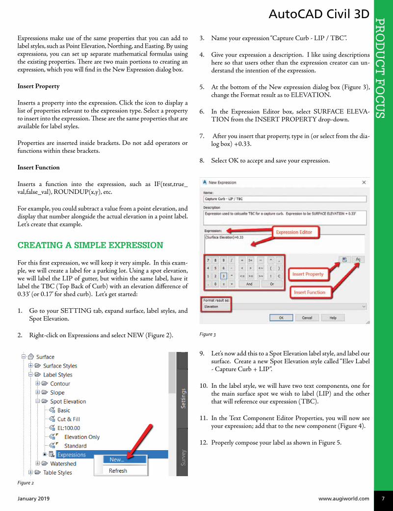
1. Go to your SETTING tab, expand surface, label styles, and Spot Elevation.
2. Right-click on Expressions and select NEW (Figure 2).
Figure 2
3. Name your expression “Capture Curb - LIP / TBC”.
4. Give your expression a description. I like using descriptions here so that users other than the expression creator can un-derstand the intention of the expression.
5. At the bottom of the New expression dialog box (Figure 3), change the Format result as to ELEVATION.
6. In the Expression Editor box, select SURFACE ELEVA-TION from the INSERT PROPERTY drop-down.
7. After you insert that property, type in (or select from the dia-log box) +0.33.
8. Select OK to accept and save your expression.
Figure 3
9. Let’s now add this to a Spot Elevation label style, and label our surface. Create a new Spot Elevation style called “Elev Label - Capture Curb + LIP”.
10. In the label style, we will have two text components, one for the main surface spot we wish to label (LIP) and the other that will reference our expression (TBC).
11. In the Text Component Editor Properties, you will now see your expression; add that to the new component (Figure 4).
12. Properly compose your label as shown in Figure 5.

AutoCAD Civil 3DP
RO
DU
CT
FO
CU
S
8 www.augi.com January 2019
Figure 4
Figure 5
13. Now use the ADD LABELS dialog box to add the newly cre-ated label to a few spots. You can now see that by labeling the one spot, the mathematical equation we set up in the expres-sion will then add the 0.33’ we specified (Figure 6).
Figure 6
Now let’s try some more advanced expressions!
EXPRESSION FOR CUT / FILL TEXT
Another useful example for expressions is to use them to aid in labeling cut versus fill labels in a volume surface. For example, you may want to display your CUT in red, and your FILL in blue. To do so, we will set up a couple quick expressions.
1. First, ensure you have a VOLUME surface created. This goes without saying, but I thought I would mention it anyway!
2. Create two expressions, one for the Cut Text height and one for the Fill Text height.
3. Name this first expression Cut-Text. Use this as the expres-sion:
a. IF({Surface Elevation}<0,0.10/12,0.00000001)
4. Name this second expression Fill-Text. Use this as the expres-sion:
a. IF({Surface Elevation}<=0,0.12/12,0.00000001)
Here, we are creating a super small text that will NOT show up once we place our labels. These expressions are slightly different. We won’t use them in our label composer, but we will use these to adjust the text height and differentiate Cut versus Fill.
5. Create a label style that has two components: Cut and Fill text (see Figure 7). These components reference the Surface Elevation, but in the text height property, you will set the cor-responding expression (Cut/Fill).
6. Change the CUT component color to RED.
7. Change the FILL component to BLUE.
Figure 7
Test this out by using your new label style to label a surface (Figure 8).

AutoCAD Civil 3D PR
OD
UC
T F
OC
US
January 2019 www.augiworld.com 9
Shawn Herring has been a part of the design engineering community for roughly 14 years in all aspects of design, construction and software implementations. He has implemented and trained companies across the country on Civil 3D and other infrastructure tools and their best practice workflows including many reality capture workflows. Shawn can be reached for comments or questions at [email protected].
Figure 8
EXPRESSION FOR PIPE CALCULATIONS
Want to have dynamic flow rates or velocities for your gravity networks? One way to do so is to create an expression utiliz-ing the Manning’s equation to get the flow rate (Q) and the flow velocity (V)
The expression for Q for feet drawings is:
1.486*pi*((({Start Crown Elevation}-{Start Invert Eleva-tion})/2)^2)*(1/{Manning Coefficient})*((({Start Crown Elevation}-{Start Invert Elevation})/4)^(2/3))*(SQRT({Pipe Slope}))
Once we have completed the expression for Q, we can create the expression for V (or other calcs):
Q/(pi*({Inner Pipe Diameter}/2)^2)
Time in Pipe could be another necessary calculation:
{2D Length - To Inside Edges}/Velocity/60
MISCELLANEOUS EXPRESSIONS
Here are a few others I’ve used in Civil 3D.
Truncate your elevations. An example of this is displaying an elevation of 132.67 as 32.67:
• {Surface Elevation}-100*TRUNC({Surface Eleva-tion}/100)
Two-Point Slope Arrow—arrow always pointing downhill (Figure 9)
• IF({Surface Slope} <= 0, 0, pi)
• This expression gets applied to the Rotation Angle of the di-rection arrow component.
Figure 9
Pipe True Slope
• ({Start Invert Elevation}-{End Invert Elevation})/{2D Length - To Inside Edges}
Length in Meter – Display both (any object):
• {Segment Length} *.3084
Slope Distance AND Horizontal Distance in a label (use on lines, polylines, figures, and feature lines):
• SQRT({General Segment Length}^2-(ABS({General Seg-ment Start Z}-{General Segment End Z})^2))
CONCLUSION
There are MANY expressions you can create within Civil 3D. Hopefully this helps get the brain going and thinking about how you can further increase your productivity by testing the limits of label styles and expression composition.
As always, I am interested to hear what you think and see how we can improve upon this topic. If you have some crazy cool expres-sions, I’d love to see them in action. Shoot me an email or connect with me on LinkedIn.
Good luck, and EXPRESS YOURSELF!!

10 www.augi.com January 2019
PR
OD
UC
T F
OC
US by: Brian ChapmanInfraWorks
In this article, I’ll present some functions built inside InfraWorks® that some may not realize are available, and offer tips on ways they can be used.
OVERLAYS
The ability to overlay data onto our terrain is essential for proper presentation and is virtually the foundation of InfraWorks. While
A New Look at Familiar Features
most are familiar with overlaying aerial content, fewer are famil-iar with using the same function to present more complex content such as pavement striping and walls. For example, if we want to quickly present the appearance of retaining walls without spend-ing hours modeling them in applications such as Civil 3D®, we can simply drape a shapefile (.shp) generated from a polyline in Civil 3D onto a surface modeled with the appropriate break lines and assign it a material similar to the type of wall we are proposing. See Figure 1 for example.
Figure 1: Wall example

January 2019 www.augiworld.com 11
InfraWorks PR
OD
UC
T F
OC
US
MATERIALS
Figure 1 also displays a custom rock wall type. InfraWorks al-lows us to apply custom materials to our objects so we can pres-ent our project any way we would like. Using this feature we can assign images to billboards, photos of the facades of buildings to 3D content, signs, window displays, and more. This gives us all the flexibility we want. See Figure 2 for an example of a custom image placed on a 3D billboard.
ANIMATIONS
InfraWorks allows us to import animated content built with soft-ware such as 3ds Max®. A common workflow is to obtain content needed from sites like 3D Warehouse and use the animation tools inside 3ds Max to modify it. Once complete, the file can be exported to Collada (DAE) file format and imported into InfraWorks. Dave Tyner presented a very good example online here: https://youtu.be/GZp0eCpzNfI
TRANSLATION
One of the most powerful features in InfraWorks is its ability to translate data into FBX format. This format is used in most of the popular 3D presentation and animation software available to-day, including 3ds Max, Unity, Unreal, Maya, Lumion, and many more. This makes it a powerful tool for quickly converting content generated in software such as Civil 3D to something presentable. By using this feature we can take data we’ve already constructed (surfaces from Civil 3D, Revit® models, etc.) and place them in a virtual environment in an extremely short amount of time.
Brian Chapman is an Autodesk Authorized Developer, creator of Pro-Cad.Net, and Senior Designer for Westwood Professional Services. Brian can be reached at [email protected].
Figure 2: Material example

Revit StructureP
RO
DU
CT
FO
CU
S P
RO
DU
CT
FO
CU
S
12 www.augi.com January 2019
by: Alex Mercado
Typically, in structural framing plans when indicating a beam above or below your modeled beam(s), users tend to just add a 2D line adjacent to the beam(s). On the
one hand, this is an easy solution; on the other hand, you run the risk of having an errant line on your drawings if that beam were to move or be deleted. The following is a step-by-step instruction for adding the 2D line directly to the Beam family with the ability to turn it on/off and to offset the beam all within the Family Properties.
DUPLICATE A BEAM FAMILY
For the purpose of this exercise I duplicated the W-Wide Flange beam family found in the Imperial Library under Structural Fram-ing. Do a “Save As,” rename the beam family, and save in your ap-propriate family/ project folder.
Adding a Beam to a
Beam Family
Figure 1: Beam Save As
Revit Structure PR
OD
UC
T F
OC
US
January 2019 www.augiworld.com 13
CREATE SHARED PARAMETERS
The purpose of creating these Shared Parameters is to control the visibility of the 2D lines that represent a structural beam above or below another beam.
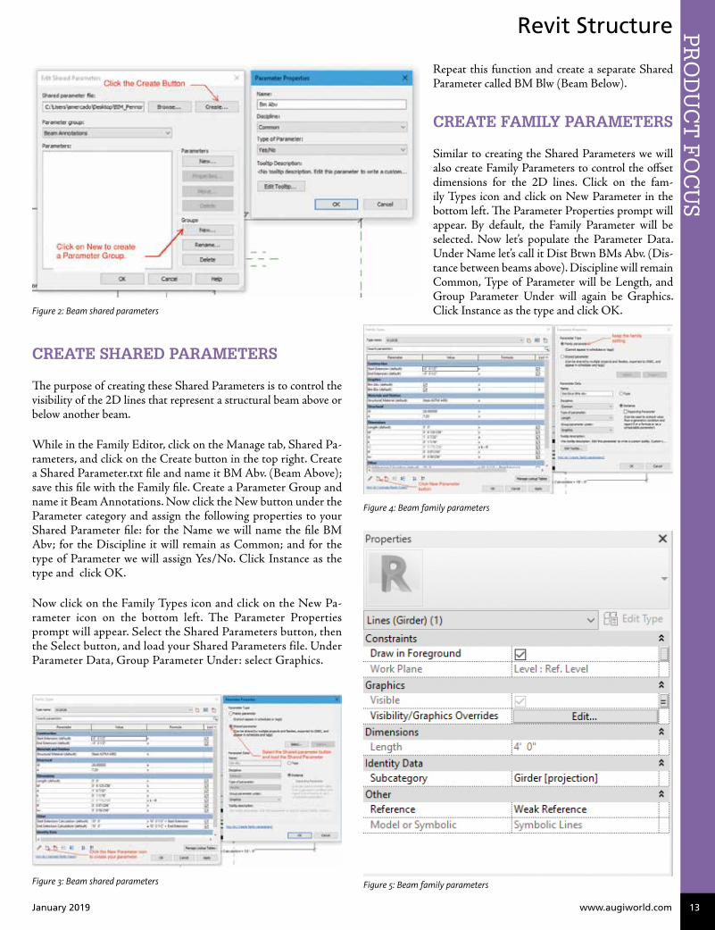
While in the Family Editor, click on the Manage tab, Shared Pa-rameters, and click on the Create button in the top right. Create a Shared Parameter.txt file and name it BM Abv. (Beam Above); save this file with the Family file. Create a Parameter Group and name it Beam Annotations. Now click the New button under the Parameter category and assign the following properties to your Shared Parameter file: for the Name we will name the file BM Abv; for the Discipline it will remain as Common; and for the type of Parameter we will assign Yes/No. Click Instance as the type and click OK.
Now click on the Family Types icon and click on the New Pa-rameter icon on the bottom left. The Parameter Properties prompt will appear. Select the Shared Parameters button, then the Select button, and load your Shared Parameters file. Under Parameter Data, Group Parameter Under: select Graphics.
Figure 3: Beam shared parameters
Repeat this function and create a separate Shared Parameter called BM Blw (Beam Below).
CREATE FAMILY PARAMETERS
Similar to creating the Shared Parameters we will also create Family Parameters to control the offset dimensions for the 2D lines. Click on the fam-ily Types icon and click on New Parameter in the bottom left. The Parameter Properties prompt will appear. By default, the Family Parameter will be selected. Now let’s populate the Parameter Data. Under Name let’s call it Dist Btwn BMs Abv. (Dis-tance between beams above). Discipline will remain Common, Type of Parameter will be Length, and Group Parameter Under will again be Graphics. Click Instance as the type and click OK.
Figure 4: Beam family parameters
Figure 5: Beam family parameters
Figure 2: Beam shared parameters

Revit StructureP
RO
DU
CT
FO
CU
S
14 www.augi.com January 2019
CREATE A LINE TYPE FOR 2D BEAM
In the Family, the line you will use to represent the beam above or below must match the line type you use in your project template. For this example, I am matching our Girder type. In my Project template file, I click on the Manage tab, Object Styles and I scroll down to Structural Framing to review what my Girder line type is set to. In the Family click on the Manage tab, Object Styles, and select New to create a new line. Call the line Girder and assign the same Line Weight, Line Color, and Line Pattern as the Project Template file.
ADD GRAPHICS AND ASSIGN PARAMETERS
We are now ready to start drawing our “beams” and assigning the parameters we created so we can graphically control how we represent beams above or below in our framing plans. Click on the Annotate tab, Symbolic Line and draw a “beam” the same length and above (Plan North) as the modeled beam. Click on the line. In Properties, click on the Visibility/Graphics Over-rides tab. Make sure the Detail Levels are only set to Coarse and Medium, click OK. Under Visible, click on the small Associate Family Parameter button and select the BM Abv Parameter.
Repeat these steps and create a “beam” below (Plan South) and assign the BM Blw parameter.
Next, we will assign the Family Parameters to control the dimen-sional offset of the beams. Click on the Annotate Tab and select the Aligned Dimension. Add a dimension from the center line of the modeled beam to the centerline of the Abv (Plan North) 2D beam. Click on the dimension and assign the Dist Btwn BMs Abv parameter. Repeat the same process to the beam below using the Dist Btgwn BMs Blw Family Parameter.
The completed family should look like Figure 9.
Figure 6: Beam family parameters
Figure 7: Beam family parameters
Figure 8: Beam family parameters
Repeat this function and create a separate Family Parameter called Dist Btwn BMs Blw (Distance between beams below).

Revit Structure PR
OD
UC
T F
OC
US
January 2019 www.augiworld.com 15
Alex Mercado has roughly 20 years of AEC experience with an emphasis on design, production, and BIM in Architectural, Structural, and Interior design. He is the BIM Manager at Pennoni Associates Inc.
Figure 9: Beam parameters complete
PARAMETER REVIEW PRIOR TO USE
Prior to loading the family into your project, you should confirm that the Value Setting for the BM Abv, Blw Parameters are Un-checked. This will ensure that when you load the family it will come in without the 2D linework.
Figure 10: All parameters in family
USE OF FAMILY IN A PROJECT ENVIRONMENT
The family is ready for use in your project. Once in your project environment, click Insert, Load family, and navigate to the Beam family. Model your structural framing plans using this family and you now have the ability to add a beam, graphically, to your Beam family. Please note that this can be replicated into any Structural Framing family where you may need to indicate a structural mem-ber above or below.
Figure 11: Beam properties in project

Share your knowledge and showcase you and your company’s talents!Submit your ideas and join our community of experts in the Built Environment.
To find out more visit: www.dbeinstitute.org/events
RTC Events Management
[email protected]@BILTevent
SUBMIT NOW!
ABSTRACTS NOW OPEN!
BILT EUROPEOctober 10-12, Edinburgh, Scotland
Abstracts close January 29
DIGITAL BUILT WEEK NORTH AMERICAJuly 17-20, Seattle, WA
Abstracts close January 7


Revit ArchitectureP
RO
DU
CT
FO
CU
S P
RO
DU
CT
FO
CU
S by: Kelly Cone
18 www.augi.com January 2019
While traveling home I read “Software That Should Be Unifying the AEC Industry Is Impeding Progress and Innovation” by Carl Galioto, presi-
dent of HOK, and it inspired me to crack open the computer on the plane instead of finishing the last episode of Ozark I was halfway through from the first flight. If you know me, you know that’s some crazy stuff: I can’t start a book, TV show, or movie without finishing it in one sitting (which leads to some epic late nights on some books). So this article clearly got me worked up.
Now, to be clear, it is a well-written article that makes some great points and highlights some of the challenges facing our industry as a whole with current software solutions. I love some of the obser-vations, in particular this quote that got me out of my seat, shout-ing hallelujah:
“If we think of software and technology as tangential to the “real” prob-lem of creating buildings, then we have lost. It is essential that we think of technology as the means by which the art, science and craft of build-ing is achieved in a collaborative and holistic environment that bridges the AEC industry.”
Preach it, Carl, preach it! So I highly recommend you read it and share your own thoughts about it. Ultimately, I agree with probably 90 percent of the article’s content. At the detailed level, I’ve felt those pains as a user, BIM manager, VDC director, and purchaser of the products we have to choose from. But scattered throughout the observations and frustrations that I so complete-ly relate to is a tone of blame that just broke my heart. This bit is the most obvious:
“We cannot wait for the software vendors to develop better tools. We must demand more from them...”
Please, Don't (Just) Blame the Tech
Revit Architecture PR
OD
UC
T F
OC
US
January 2019 www.augiworld.com 19
Basically the last three paragraphs are a call to action to “demand” vendors provide the tools to lead our industry to the promised land of integrated data systems and integrated delivery. Because clearly it is the vendors that are withholding said software and preventing the industry from moving forward. Right...
Why, Carl, WHY? Our industry is already plagued with a “blame the other guy” mentality. It is a cold day in hell when a prominent industry leader stands up and says, “It’s our fault. We screwed this one up, and we need to fix it.” Mad props to the few who have! Instead, I almost always hear: “The Contractors screwed up the es-timate.” or “The Architects gave us crappy drawings.” And so on. I’m just sick of it. And, while this article started so well, it ultimately ends up pointing the finger of blame squarely at technology and the software and hardware vendors that make it. Oh well...
Now, you may be thinking: “Who are you to talk, Kelly? You work at a software vendor. #bias dude...”
But hey, I worked at the Beck Group for 10 years, and Beck has gone farther than most firms by functionally combining an ar-chitecture firm and a construction company into a single opera-tional business. So we constantly struggled against the software not supporting the level of cross-discipline collaboration that we desperately needed. I have been in Waltham and Manches-ter (The Gracelands of Revit) talking to Anthony Hauk and Jim Lynch ad nauseam about why they need to fix this. I’m all for fixing it. But, there’s a really really really ugly reality—the BIG problem—that this article glosses over in a single sentence. ONE SENTENCE:
“We live with it every day and fully realize how contractual barriers limit software interoperability and the efficient flow of information.”
Come on, Carl! So you want us to build software that you contractually can't use?? I'm pretty sure that's going to be a flop. When cloud-based project information management systems came out, everyone complained that they needed an on-site dis-connected version for their government jobs because they couldn’t use web-connected systems on those projects. They didn’t all jump up and down shouting, “Hooray, let’s stick it to the man!” When umpteen companies created tools to share models between the contractor and the architect, guess who used them? Almost no one, because the contracts don’t recognize BIMs or 3D models of any kind as contract documents. When BIM 360 got that awesome feature to automatically print drawings to PDF when the model changed so the contractor would have up-to-the-minute updated drawings, everyone in the industry looked gleefully at each other and whispered #awkward behind their hands because (GASP) until it has been approved for construction by the owner, the con-tractor would be financially at risk if they used them. So, without further ado, in direct response:
Carl, I work at a company that is trying to solve two of the many remaining problems that prevents the vertical construction industry from reducing the rampant waste that comes from mistakes and miscommunication—and that means our software
that straddles the silos you so eloquently lament. We’re doing what you’re demanding, and let me tell you it is a really tough row to hoe.
We make software that helps automate the process of generating 3D models and BIMs from reality capture data. Our software can cut in half (or more!) the time it takes to turn a laser scan into a useful as-built model to serve as an accurate basis of design.
Let's face it, this is a HUGE problem plaguing adaptive reuse proj-ects. In a perfect world, architects and engineers would be falling over themselves trying to buy our software. We’d be fighting off hordes of angry, credit-card-wielding studio zombies who want to work 40-hour weeks instead of 60-hour weeks. But, in reality, the #1 thing I hear from A and E prospects is:
“That isn’t our contractual responsibility; we don’t want to take on any liability for the as-built drawings to be correct.”
If that wasn’t awful enough, I even got this lovely addition recently:
“If we use your software we’re worried it implies a level of accuracy that will put us implicitly at risk.”
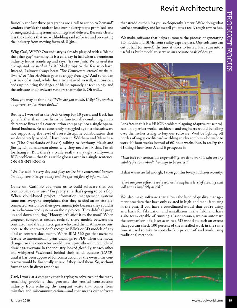
We also make software that allows the kind of quality manage-ment practices that have only existed in high-end manufacturing in the past. If you have a coordinated model that you’re using as a basis for fabrication and installation in the field, and have a site team capable of running a laser scanner, we can automate the comparison of a laser scan to a 3D model to such an extent that you can check 100 percent of the installed work in the same time it used to take to spot check 5 percent of said work using traditional methods.
Please, Don't (Just) Blame the Tech

Revit ArchitectureP
RO
DU
CT
FO
CU
S
20 www.augi.com January 2019
So basically, we made software that can provide an extremely ef-ficient path to fine-grained progress tracking, validation of con-formance to specs, and ultimately establish accountability for the trades to follow the coordinated model. This conveniently short circuits the massive issues we have in turning over accurate as-built drawings and models to our owners. After all, if it is built in the in-tended spot, the shop drawings ARE the as-builts. So surely, we’d need razor wire and Blackwater private security at the gate at all our conference appearances to manage the unruly mobs of general contractors desperate to buy our kit to solve all their problems! HA! And don’t call me Shirley! Instead, the most common thing I hear is:
“Well, if the owner found out how much stuff was wrong we’d be out of a job.”
...or...
“Quality is really the subcontractor’s responsibility, and we don’t want to take on that risk.”
...or...
“We make most of our money through change orders; this would basi-cally eliminate most of our profit on construction jobs.”
That’s my personal favorite. But I shouldn’t be surprised. One of my first times working with ClearEdge3D to try and implement EdgeWise at Beck, I had to explain that since some of our scan-to-BIM service work was on negotiated hourly rates set in advance that we would never use EdgeWise on those jobs because it would cut our revenue in half (or worse!). So I’ve seen it from both sides.
Are there firms that find ways to apply our technology to their operations without crossing the legal demilitarized zones that ex-ist between disciplines? Of course! (I still have a job, after all!) Are there firms that leverage unique business models to get around some of those DMZs and use our technology more effectively as a result? Of course! But I can’t tell you how much of a battle each and every initial sale is, despite our active customers’ willingness to unabashedly interject into private conversations to rant and rave about how amazing our software is once you realize how much time it can save you.
So here’s the reality. Our industry is sick. Fifty shades of grey per-verse. And, 95 percent of that weird, nasty, adversarial S&M stuff we live with day to day as our “normal operations” in this business comes from our contracts. Those standard contracts upon which most contracts are based (in the US) are authored by the AIA and the AGC. And, this isn’t unique to the US. The truth is:
“WE DID THIS TO OURSELVES!”
It took us 75 years to screw things up this bad, but by George we did it! Hip, hip, hooray!
Technology companies are FAR more agile than our AEC firms when it comes to adjusting their strategies to changes in the in-dustry; even “uge” ones like Autodesk or Bentley. Like, an order of magnitude more agile. “We” (the royal “we” meaning “technol-ogy companies”) can shift gears in months, not years. Technol-ogy companies are also driving some of the changes in formats and standards (IFC, E57, etc...); we’re closely engaged in industry think-tanks; we’re sponsoring and leading initiatives in industry organizations like the AIA, AGC, CSI, USIBD, etc; we’re driv-ing the use of the cloud to enable collaboration; we’re working to change contracts and legal language to make new technologies pos-sible to use on highly secure projects through certifications and other programs. Are we doing it in a somewhat self-serving way? Sure. We’re businesses. Our job is to make money (something the architectural profession seems to have forgotten at some point in the distant past). But, we ARE pushing the industry forward in ways we believe we can influence ourselves.
It’s not like we’re your over-protective bro who’s holding you back from a fight to defend your girlfriend’s honor at some crappy bar in the middle of nowhere. We might, however, be your bro that you asked in advance to make a show of holding you back so you didn’t actually have to fight, but your girlfriend would still be im-pressed because you “stood up for her.” That seems like a way more accurate (although still totally misogynistic) analogy in this situa-tion. Fortunately, in this analogy your “girlfriend” is the owner. You know, the ones with all the real power and money in this scenario. So don’t get too upset at me for using it. It works because we’ve all seen that jerk at a bar playing like he’s going to beat someone else up because they said something they shouldn’t have, but then keeps hitting some invisible wall every time he puffs up and thrusts himself at some other dude.
“Hold me back, Bro!”
Also, “we” ARE providing tools that break down or bridge the si-los. Those tools exist. They exist in the applications your firm and every other design or construction firm worth noting is using. For instance: You do realize that C4R can allow contractors and archi-tects and engineers to work collaboratively on the same BIM all at the same time, right? How’s that for breaking down silos? But the industry doesn’t use silo-busting (or silo-ignorant) functional-ity because it is contractually off limits. So, that functionality sits there like Beatrix Kiddo in a coma as its muscles atrophy and com-panies move on to find other less-silo-busting uses for the technol-

Revit Architecture PR
OD
UC
T F
OC
US
January 2019 www.augiworld.com 21
ogy they built. Unlike in "Kill Bill," it never wakes up and busts in Buck’s head with a door, steals his inappropriately named vehicle, and drives off into the sunset to exact revenge on the baddest posse of assassins that Quentin Tarantino could imagine. That’s not real-ity. In the real world, the architects, engineers, and contractors get together and hire a bunch of lawyers to see to it that it never wakes up evil “pirate-nurse” style.
We don’t live in a “Field of Dreams” industry unburdened by regulation or standards where if the technology company builds it, “they” will come. We work in one of the most highly regulated industries (by volume of regulation) that exists. I’ve seen count-less start-ups and big-company initiatives go bust in the last 15 years because they ignored that constricted reality and dreamed too big in their own silo-busting, industry-disrupting ways. Tech-nology companies could build the coolest, most integrated, most open technology infrastructure possible—invest billions in mak-ing something truly revolutionary that could bring our professions into the 21st century (and beyond!)—and they’d go bankrupt do-ing it because no one would be there to use it. Just a cool product sitting in a cornfield with no one to play ball…
But Kevin Costner would be so proud!
So, Carl, while I whole-heartedly agree with your frustration, your observations, and your desire to change the status quo, it isn’t the vendors of our software and hardware that the industry needs to focus our demands for change upon. “WE” (everyone in and adja-cent to the AEC industry including owners, designers, builders, fab-ricators, suppliers, etc.) should be focusing our demands upon our own industry organizations to not only support, but to enable this change. All of us (including technology vendors) share blame for the mess we’re in. Our technology is absolutely a speed bump on the road to industry nirvana. But that speed bump sits behind a Great Wall of China-sized edifice made of decades of risk-averse contracts, disclaimers, court precedents, and God only knows what else our in-dustry “advocacy” groups’ hired lawyers piled up to point the fingers of blame in so many directions no one can figure out who’s blaming whom when projects go wrong. I’ve been brought in as an expert wit-ness on litigations—and it is like an Abbott and Costello “Who’s on first” comedy act—but somehow disturbingly sad at the same time.
Let’s demand that those same groups (like the AIA and AGC) start dismantling that wall so we can all individually get back to what we presumably got into this industry to do in the first place:
Making amazing places, and making a reasonable amount of money doing it.
Once we knock down that so-big-you-can-see-it-from-space bar-rier; then by all means let’s grind down that speed bump Autodesk and others have put in our path by letting their interoperability and multidisciplinary collaboration efforts atrophy. But just removing the speed bump isn’t going to do a damn thing by itself, and that’s why I wanted to cry at the end of the article. Over-simplification is a skill required for any decent architect to succeed, but that doesn’t mean it should be over-employed when all it does is obfuscate the
real challenges that something as small as a project or as large as an entire industry currently face.
On the bright side (sarcasm), if we don’t fix it ourselves, WeWork, Katerra, and other developer/owner/operator led vertical integra-tions will just eventually push traditional AEC firms to the un-desirable margins of the industry, leaving only the rare starchitect (a thing), starengineer (barely a thing), and starcontractor (totally not a thing) to carry on the banner of our professions as a stand-alone service to the universe. Huzzah! Alas, that is probably the most likely outcome at this point. It will take decades to come to pass, but make no mistake—that is a train coming toward you in the tunnel. It isn't moving fast, but it is coming whether you're ready for it or not.
But, hey, that’s all my unsolicited opinion on rhetorical display. (Grandiloquent, even?) Take it with a grain (or entire ocean’s worth) of salt as you see fit. And no, dear reader, I don’t know Carl from Adam, but sometimes it is fun to talk to people you don’t know and who aren’t there as if they were listening. Or maybe I’m crazy. Or both. One thing’s for sure—one-sided arguments are al-ways easier to win. ;-)
See you around the blogosphere, C-train! (my new rapper nick-name for my buddy Carl!)
Kelly Cone, LEED AP, is Vice Presi-dent of Product Management for ClearEdge3D Inc. In his words: “I am passionate about process and technology innovation and how they can change industries and people's lives. My educa-tion is in architectural design and docu-mentation, but my experience within the AEC space is far more varied. I have implemented various practice tech-nologies into design, estimating, and con-struction teams and workflows; worked on amazing projects such as the SaRang Global Ministry center in Seoul as a de-signer, and Renzo Piano's addition to the Louis Kahn Kimbell Art Museum as a contractor; and have had the privilege of growing and leading one of the most talented VDC & Process Innovation teams in the industry. Those experiences have taught me there is a better way to create our built environment, and I want to make that way become a reality. As a first step in that journey, I have joined ClearEdge3D to help them develop the tools necessary for design and construc-tion firms to get the most out of reality capture within the AEC industry; with the goal of closing the gap between the virtual and real world.”

22 www.augi.com January 2019
3ds Max 2019P
RO
DU
CT
FO
CU
S by: Brian Chapman
This article will focus on tips advanced users of 3ds Max® apply to improve the realism of our renderings and the tools available to us through the Vray Frame Buffer. At the
bottom of the frame buffer, you’ll find several icons representing options available to us. Using these options, we refine our renderings. Figure 1 identifies the items we’ll be discussing.
Figure 1: Vray frame buffer
COLOR CORRECTIONS
The first icon opens the Color Corrections options displayed on the right side of Figure 1. These options can help reduce the need for post-processing and speed up production. The op-tions we’ll cover are Color Clamping, Levels, Curves, Exposure, and Lens Effects.
COLOR CLAMPING
Ensuring the light is balanced in a scene helps it appear more nat-ural and real. Essentially this is a step in our production where we review if shadows are too dark or ensure the lights aren’t too bright, washing out details from our scene. The color clamping tool can be used as an option to assist with this process. By disabling the Forced Color Clamping icon, the Vray Frame Buffer will iden-tify the areas of our image that are over-exposed. See Figure 2 for example. With the Vray Frame Buffer, we can correct this by ad-justing the exposure. As we slide the exposure up and down we’ll see the highlighted areas adjust accordingly.
Advanced Tips for More Realistic
Visualization

January 2019 www.augiworld.com 23
3ds Max 2019 PR
OD
UC
T F
OC
US
Figure 2: Over-exposed areas
Using this option tends to adjust our images. To counter the nega-tive effects from that adjustment without re-rendering or adjusting lighting, we use the Curves tool. A typical s-curve shape will typi-cally counter this adequately. See Figure 3 for example.
Figure 3: Color curve
LENS EFFECTS AND TIPS
The lack of particulates in a rendering or elements such as volumet-ric light and bloom can make a considerable difference in how realis-tic the image appears. This is because both real atmosphere and cam-eras have particles our eyes naturally attune to. Excluding elements like these is one of the quickest ways to break a viewer’s immersion. Adding elements like these helps to ensure the image appears more
natural and reflects the mood of a scene. See Figure 4 for an exag-gerated example, where the fog was added to the right option in an effort to portray a colder environment and atmosphere.
It is very important that no matter how little the effect, we work to add the proper elements to our scenes to mimic atmospheric con-ditions and imitate the effects real cameras produce. Chaos Group recognized that one such element was bloom. Bloom is essentially the component that appears around any light source, or lighting in general, and is generally present in all circumstances, although not always so noticeably. See Figure 5 for examples of a bloom effect from a real candle and Figure 6 where the bloom effect is consider-ably less noticeable. The great thing about the Vray Next Frame Buffer is that we can select the Lens Effects icon to add bloom and adjust it however we like, watching it update in real time.
Figure 5: Bloom effect
Figure 6: Limited bloom effect
Brian Chapman is an Autodesk Authorized Developer, creator of Pro-Cad.Net and a Senior Designer for Westwood Professional Services located in Las Vegas, Nevada. Brian can be reached at [email protected].
Figure 4: Adding fog

24 www.augi.com January 2019
CAD ManagerC
OL
UM
Nby: Mark Kiker
24 www.augi.com January 2019
In the last issue we reviewed six questions we did not want our boss to ask us. If the boss comes to your office and asks them, you need to be ready with an answer. Better yet, work hard so
your boss won’t be asking these questions at all. If you missed that article, go back to the December 2018 issue of AUGI-World and review it.
This time we look at a longer list of questions you should be asking your boss.
I take away a lot from the questions people ask me. They are usu-ally tipping their hand to what is on their minds, unless they are just asking for data or on a fact-finding mission. If it is an open-ended question, there is usually some perspective or stance behind it. When you talk to your boss, he or she may be thinking, like I do… “Why are you asking?” And your boss may actually say that.
I usually ask that same thing to wide-open questions, unless I think the person just wants information. Then about halfway through my dissertation I realize that they are blurry eyed and overwhelmed, so I stop and ask, “What were you wanting?” So make sure you have some backstory behind your questions.
Sometimes there is something you want to get across and the best way to approach it is to pose a question to introduce the
topic. I find that if I want to start a conversation, a question is a good place to begin. And yes, you have to listen to the answer and take any advice given. Don’t ask a question you are not ready to hear them answer.
WHAT TO ASK YOUR BOSS
Ask your boss: What’s next?
What you are telling them: I know what we should do, let me tell you.
As a manager of people and technology, you should know what will be coming next. If you are a planner, you have a good idea of what the firm needs. But you may not have the entire picture. You see only what is shared with you. You see only what people want you to see.
What about those items that upper management has not shared yet? They might be roadblocks. Ask this question, then listen to the response to see if it meshes with what you have in mind. Don’t just spill out your magic roadmap to the future. Let management tell you where they think you are headed. If is blends with your ideas, then bring them up. If it does not lean toward your defined target, maybe you need to rethink things before launching into your master plan for productivity and progress.
Eight Questions You Should be Asking Your Boss

January 2019 www.augiworld.com 25January 2019 www.augiworld.com 25
CAD Manager CO
LU
MN
Ask your boss: Why are we doing that?
What you are telling them: I have a better way.
Like many of these questions, what the boss is thinking might be positive or negative. They may take what you say as a challenge to their authority or an encouragement to think. You may not know how it will be taken. This question is one that could go both ways. The question may be related to their pet project or some outdated process or procedure that they created back in the day. Go lightly into these waters. You need to listen to the response and validate what they provide. It may be that something was done specifically for some reason and you should not propose changes. Other items may lower the boss's brow in contemplation of a change because they do not know why something continues as it has since the dawn of time. They may be ready to change, or they may dig in their heels. Be ready.
Ask your boss: Can I help you with anything?
What you are telling them: I am ready for a new challenge.
Most bosses will take this as an offer to help. Others might take it as a questioning of their competency. If your relationship has been built over the years, your boss will take this in the spirit in which it is intended. You really are willing to help. They seem stretched and you are offering to take something off their shoulders. Be prepared to take on whatever they give you. It may not be the best task, but it helps them out. Embrace it.
Ask your boss: How did you get where you are?
What you are telling them: I want to advance with the firm.
This is asking them for career advice. You want to know what steps they took. Who they connected with. What training they received. How they made the jump in job titles in the past. So often we turn away from the best career coach we may have—our boss. They have the talent and skill to navigate the firm’s ladder. They have advanced inside and outside the company. They know a lot about career planning. Make sure they understand that you want to grow with the firm, not jump ship.
Ask your boss: How would you suggest I approach this?
What you are telling them: I value your knowledge, wisdom, and advice
Your boss has been down the road farther than you (most of the time)—worked on tech longer, or with people more, or on diverse projects. They have the skills needed to do their job and they can help you do yours. They may have another point of view that you have not thought of. Take what they tell you and put it into prac-tice (if it is on target). When the boss gives advice, you need to put it in play.
Ask your boss: What is most important to you?
What you are telling them: I want to know what you need me to get done.
Mark Kiker has more than 25 years of hands-on experience with technol-ogy. He is fully versed in every area of management from deployment plan-ning, installation, and configuration to training and strategic planning. As an internationally known speaker and writer, he is a returning speaker at Autodesk University since 1996. Mark is currently serving as Direc-tor of IT for SIATech, a non-profit public charter high school focused on dropout recovery. He maintains two blog sites, www.caddmanager.com and www.bimmanager.com .
This is a really open-ended question… are you asking about life in general, tech tasks, project lists, initiatives, character traits, or what? I kind of like these types of questions and usually tell the person I am asking that they can take it any way they want. If their reply is way off base from where I may have wanted to take it, I thank them for the info and then I divert back to my focus, “…and how about software upgrades? What is most important to you with those?” A little back and forth and clarification, then you have your marching orders. The boss may say, “Don’t do too much too fast, get upgrades done after hours, include training, and if a proj-ect is almost done, hold on the upgrade until after the submittal.”
Ask your boss: How am I doing?
What you are telling them: I am hoping for some encouragement.
You are hoping for some positive feedback. A hearty pat on the back. But you might get some negatives, too. Hopefully, your boss will offer some positives. They like that you are checking in and that you are willing to make some course corrections as you move forward.
Ask your boss: What should I be doing differently?
What you are telling them: I am also open for critique.
You are open to changing how you do things, right? This one is in-viting adjustments. It gives your bosses an opening to discuss areas of improvement. If they are coaches, they will seek to shape and mold your approaches and stances. They will optimistically give you feedback that makes you a better employee. They want you to succeed. But if they are harsh critics, then go cautiously with this question. They will expect instant, exact, and lasting changes.
With these, and more that you can think of, you will be opening a conversation with the boss that, with any luck and a good boss, will end in improved relationships and expanded opportunities at work. Be bold and ask.

PR
OD
UC
T F
OC
US AutoCAD Architecture 2019
PR
OD
UC
T F
OC
US
26 www.augi.com January 2019
by: Melinda Heavrin
Spaces are two-dimensional or three-dimen-sional style-based architectural objects that contain spatial information about a building, including floor area, wall area, volume, and
surface information. Spaces have a multitude of uses, spanning the conceptual design through construction documents phases of a project. Among other things, spaces can begin to define the layout of a building’s internal rooms and areas. They can also define rooms and areas for scheduling purposes and for area calcu-lations and evaluations.
OVERVIEW OF SPACE TYPES
Both associative and non-associative spaces can be modeled in AutoCAD® Architecture. Associative spaces are generated from boundary objects. When the boundary objects change, the space updates accordingly. In addition to associative spaces you can also create non-associative spaces with user-defined geometry. A non-associative space can stand alone in the drawing, but you can use it to generate calculations just as you would with an associative space. Non-associative spaces can be connected to boundary ob-jects after their creation; similarly, associative spaces can be discon-nected from their boundary objects.
2D spaces display spatial information in two plan dimensions. The Z direction is by default set to 0 and ignored during creating, edit-ing, and scheduling the space. 2D spaces can be rectangular or poly- gonal and they can either be non-associative or associative. A 2D space can be bounded by 3D objects and linework. 2D spaces are typically used for plan views, where 3D information is not needed.
An extruded 3D space is similar to a 2D space, but has a user-defined extrusion height. Extruded spaces are useful for regularly shaped 3D spaces such as uniform-height rooms in a building. Extruded spaces can have floor and ceiling components and space above the ceiling and below the floor. The space above the ceiling is often used to place ductwork, cables, and electrical installations in a room. Extruded 3D spaces can be associative to 3D objects and linework, but they are bounded only in the X and Y directions. The Z direction is defined by the extrusion height.
If you need a space that is fully bounded by objects in all three spatial dimensions, you need to generate a 3D freeform space. 3D freeform spaces are generated from boundary objects such as walls and slabs, and are associative to them. Associative 3D freeform spaces must be bounded in all directions to form a valid boundary shape. A 3D freeform space is a complex 3D geometry with any number of surfaces needed to generate the space shape.
Exploring Spaces in ACA
Figure 1: Ribbon

AutoCAD Architecture 2019 PR
OD
UC
T F
OC
US
January 2019 www.augiworld.com 27
SPACE STYLES
A space style is a set of parameters that determines the appearance and other characteristics of the space object to which it is assigned. Depending on the scope of the drawing, you may want to create different space styles to represent different types of spaces, such as different room types in an office building.
You can use styles for controlling the following aspects of spaces:
• Boundary offsets – You can specify the distance that a space’s net, usable, and gross boundaries will be offset from its base boundary. Each boundary has its own display components that you can set according to your needs.
• Name lists – You can select a list of allowed names for spaces of a particular style. This helps you to maintain consistent naming schemes across a building project.
• Target dimensions – You can define a target area, length, and width for spaces inserted with a specific style. This is helpful when you have upper and lower space limits for a type of room that you want to insert.
• Displaying different space types – You can draw construction spaces, demolition spaces, and traffic spaces with different display
properties. For example, you might draw all construction areas in green and hatched, and the traffic areas in blue with a solid fill.
• Displaying different decomposition methods – You can spec-ify how spaces are decomposed (trapezoid or triangular). If you are not working with space decomposition extensively, you will probably set it up in the drawing default.
Spaces can have a “Name” property assigned. These are derived from a List Definition. The List Definition should be assigned to the style so you have a valid list of names to select from when es-tablishing the space object’s properties. Space style names should be indicative of the type of room or area the space style is meant to address. Space styles should have materials assigned to their “Floor” and “Ceiling” components.
To create a space style, begin by clicking the Manage tab on the ribbon, select the Style & Display panel, and then select Style Manager (see Figure 1). The Style Manager will display with the current drawing expanded in the tree view. Expand Architectur-al Objects and then expand Space Styles. You can create a new space style by right-clicking on Space Styles and selecting New (see Figure 2).
Figure 2: Style Manager

AutoCAD Architecture 2019P
RO
DU
CT
FO
CU
S
28 www.augi.com January 2019
You can also create a space style from an existing style by right-clicking the space style you want to copy and select Copy. Next you will right-click and select Paste. Enter a name for the new space style and hit Enter. Now you will need to edit the new space style according to how the space should appear—its size, and so on. Once finished, you can add the new space style to your tool palette for easy access.
SPACE EVALUATION
The space evaluation is a documentation feature that calculates and evaluates the space information of your finished floor plan. This information is stored in a separate file that you can export to a spreadsheet or word processing application. Evaluation templates ensure that the information is formatted and arranged in a consis-tent, structured way.
Architects need the space evaluation feature for submitting floor plans to the building plan approval authorities and to customers. Space evaluation can also be used for performing cost estimates, assigning jobs to contractors, or organizing facility management. Evaluations can be created for selected spaces in the current draw-ing, selected spaces from multiple open drawings, all spaces in a drawing, and all spaces from all open drawings. Spaces can also be evaluated from external references.
Areas are converted to spaces, area groups to zones, and the area evaluation has been converted to the space evaluation. If you at-tempt to use a legacy tool or run a legacy command to start the area evaluation, the following message will appear: “The command AreaEvaluation is no longer supported” (see Figure 3). If you click Run Space Evaluation, the space evaluation will be started instead. You should remove area evaluation tools from your palettes and exchange area evaluation commands for space evaluation com-mands in your scripts.
Figure 3: Space evaluation
SPACE BOUNDARIES
Spaces have four different boundaries: base, net, usable, and gross. You can use them to display, edit, and schedule different aspects of the space. You can choose that these boundaries are not offset from each other and lie on top of each other. If you do not need different boundaries, you can even turn off the display components for the additional boundaries. Here are some typical use cases for using individual boundaries:
• Base boundary – Normally representing the inner area of a room covered by a space. This is the area generated by boundary objects in an associative space. In most cases, the base boundary is identical to the net boundary, except in some area calculation standards like the Swedish SIS standard.
• Net boundary – This boundary can be used for planning and detailed design. For example, if you need to determine the hiring of cleaning personnel for an office, you would use the net area as the calculation basis. The net boundary can also be used for special applications when the calculated area of a space is smaller than the base boundary.
• Usable boundary – This boundary is in many area calculation standards used for planning and detailed design, renting calcu-lations, tax and other duty calculations, statistical calculations, maintenance, pricing, and more. The usable boundaries typically extend from the inside of the exterior walls to the middle of the interior walls (or a specified distance into the interior walls).
• Gross boundary – The gross boundary can be used in connec-tion with cost calculation, price estimation, calculation of tax and other duties, key numbers for the building or a specific floor, and more. Normally, the gross boundary is measured from the outside of the exterior walls to the middle of the interior walls.
There are different ways to determine how the boundaries should be offset from each other and calculated. These are Manual, By Style, and By Area Calculation Standard. It is important to note that in previous versions of the software, objects that were invisible due to a frozen or hidden layer were never included in the genera-tion or update of associative spaces. Beginning with this version, frozen and hidden objects are included in the space generation and update if they are set as boundary objects.
CREATING SPACES IN YOUR DRAWING
AutoCAD Architecture provides tools that allow you to quickly place spaces by selecting a space tool with a specific space style as well as other predefined properties. You can use the tool as is with
Figure 4: Space tab

AutoCAD Architecture 2019 PR
OD
UC
T F
OC
US
January 2019 www.augiworld.com 29
its default settings or you can change any of the properties that are not controlled by the style.
You can also use space tools to apply tool properties to existing objects to create new spaces. Space tools can be found on the Space tab of the tool palette. To begin creating spaces in your drawing, drag and drop the desired space from the tool palette to your drawing and begin. You can also find space tools in the Stock Tool Catalog, the Sample Palette Catalog, and the Design Tool Catalog. Once you are in the Space command, the Space tab will appear in the ribbon (see Figure 4).
You can also create spaces in your drawing by converting poly-lines, object outlines, and profiles to spaces. Simply open the Space tool palette and right-click on the space tool you wish to use. Next, select Apply Tool Properties To and then select Linework And AEC Objects (see Figure 5). Select the objects and/or polylines you wish to convert and hit Enter. Under Cut Plane Height on the Convert to Space worksheet, enter the height at which the object should be cut to generate the profile of the new space. Select OK.
Another way to generate an associative space in your drawing is to begin by verifying that all necessary boundary objects have their Bound Spaces property set to Yes. Open the tool palette that contains the Space tool you want to use and select it. For Offset boundaries, select how the four space boundar-ies (base, net, usable, and gross boundary) are calculated:
Manual – The net, usable, and gross boundaries can be manually edited with grips.
By style – The net, usable, and gross boundaries are offset from the base boundary by a value defined in the space style.
By standard <Standard Name> – The net, usable and gross boundaries are defined by the area calculation stan-dard listed.
On the Properties palette, for Create type select Generate. It is important to note that the Associative property is in-terlinked with the Create type. If the Create type is Gen-erate, the Associative setting defaults to Yes. If the Create type is Insert, Rectangle, or Polygon, the Associative setting defaults to No and becomes read-only. Select Yes for Allow Overlapping Spaces if you want to be able to generate spac-es from boundaries that already contain a space. This could be useful if you want to generate spaces from an xref draw-ing that already contains spaces, but you need to generate spaces with different settings. For Geometry type, select 2D, Extrusion, or Freeform. In the drawing, generate the spaces. If you want to generate a 3D freeform space, enter “G” (generate all). If you want to generate a 2D or extruded 3D space, you can either enter “G” (generate all) to gener-
ate spaces for all visible boundaries, or you can pick inside closed boundaries in order to generate spaces for them.
CONCLUSION
Spaces are an essential part of AutoCAD Architecture software. They help you extract data contained in the drawing for use of scheduling, tagging, and analysis. Spaces are an integral part of en-hancing your productivity for facility management as well as the working drawing phase of your project. I encourage you to explore the possibilities with spaces and see how far you can go!
Melinda Heavrin is a CAD Co-ordinator & Facility Planner in Louisville, Kentucky. She has been using AutoCAD Architecture since release 2000. Melinda can be reached for comments and questions at [email protected].
Figure 5: Apply tool properties

AUGI Members Reach Higher with Expanded BenefitsAUGI is introducing three new Membership levels that will bring you more benefits than ever before. Each level will bring you more content and expertise to share with fellow members, plus provide an expanded, more interactive website, publication access, and much more!
MEMBER
MEMBER
MEMBER
MEMBER
MEMBER
MEMBER
MEMBER
MEMBER
MEMBER
Basic members have access to:•Forums•HotNews (last 12 months)•AUGIWorld (last 12 months)
DUES: Free
Premier members have access to:•Forums•HotNews (last 24 months)•AUGIWorld (last 24 months)
DUES: $25
Professional members have access to:•Forums•HotNews (full access)•AUGIWorld (full access and in print)•ADN2013Standard Membership Offer
DUES: $100
Are you ready to upgrade yourself and your membership? Access additional benefits and upgrade at www.augi.com

Inside Track CO
LU
MN
Inside Track CO
LU
MN
by: Brian Andresen
January 2019 www.augiworld.com 31
Welcome to AUGIWorld Inside Track! Check out the latest opportunities to advance your skills, processes, and workflows in your firm, with the most current AEC-related software and hardware updates available.
PROPERTIES+https://apps.autodesk.com/NAVIS/en/Detail/Index?id=4839143539839553081&appLang=en&os=Win64
The Properties+ plug-in allows you to select just the model prop-erties you are interested in, and displays them all together in the same window. This means you no longer have to switch between tabs to see the properties you want. You can also use the plug-in to quickly create searches for items with matching properties.
DUCTULATORhttps://apps.autodesk.com/RVT/en/Detail/Index?id=6272106374266176068&appLang=en&os=Win64
Have you ever had the task of manually resizing ducts in Autodesk® Revit® and been frustrated by the time it takes to find an old-school paper ductulator? If that is the case, then this app is for you!
With Ductulator, you will be able to resize ducts in seconds by simply selecting a duct and selecting the size of one of the sides.
Many clients have already tried this app and have directly included it in their daily processes.
BONUS TOOLShttps://apps.autodesk.com/RVT/en/Detail/Index?id=2077603980990329161&appLang=en&os=Win64
Bonus Tools contains a massive 120 apps that can help any prac-tice save time.
Some of the apps include:
• (#10) 3D Views for all Worksets − Create a 3D view for each workset and hide all other worksets in the view. Note: depend-ing on the number of worksets, this may take a while.
• (#15) Elements on Levels − Lists all elements on a selected level. Cycle through the levels in the project to see what elements are hosted to it.
• (#19) Remove Unused Views − Remove unwanted views that causes the file size to bloat. Choose between “Not placed on a sheet” or “Without a parameter of your choice.”
• (#34) Shared Parameters − Bulk load shared parameters into one or more family files.
• (#71) RDS tool − Quickly create views for each room. Create: floor plans, ceiling plans, elevations, 3Ds, schedules, and sheets for each room.
• (#87) 3D Room Tags − Create 3D room tags using a generic model family. This tool creates 3D room tags by: • Choosing the selection set, current selection, or view.• Choosing the rooms, areas, or spaces.• Selecting a generic model family. Note: A generic model
family instance must exist in the project.• Selecting parameters to map between rooms and generic
model families. Note: you must select at least the room ele-ment ID which is used for updates.
• (#98) Find Painted Elements − Find all painted elements with a project. Isolate selected elements and bulk remove paint from faces.
See the rest of the list here:
http://www.kiwicodes-support.com/Bonus_Tools_Home
If you have some news to share with us for future issues, please let us know. Likewise, if you are a user of a featured product or news item and would like to write a review, we want to know: [email protected]
AUGIWorld brings you recent developments in Autodesk and related software items

Get Real. Now.
APEXX S3, the world’s fastest workstation
purpose-built for CAD, now features real-time ray
tracing thanks to all-new NVIDIA Quadro® RTX
graphics cards. Pair these with a 9th Generation
eight-core Intel® Core™ i7 professionally
overclocked to 5.1GHz, and you’ll be ready to get
real. Now.
Design created by
Duane Addy using APEXX S3.
Amaze clients and outdistance your competition with incredible photorealistic designs.
(888) 302-0223512-852-0400
boxx.com/augiIntel is a trademark of Intel Corporation or its subsidiaries in the U.S. and/or other countries
Untitled-1 1 12/6/2018 3:12:14 PM