the non-linear sandwich structure model for low-velocity
TRANSCRIPT

Tehnički vjesnik 27, 1(2020), 5-11 5
ISSN 1330-3651 (Print), ISSN 1848-6339 (Online) https://doi.org/10.17559/TV-20170224190939 Original scientific paper
The Non-Linear Sandwich Structure Model for Low-Velocity Impact
Tomáš MANDYS, Tomáš KROUPA, Vladislav LAŠ
Abstract: This article is focused on progressive failure analysis of sandwich structure subjected to transverse low-velocity impact loading. A user defined material model considering non-linear behaviour of the composite skin of the sandwich structure was implemented into commercial software Abaqus by means of material subroutine VUMAT. The experimental measurements of transverse low-velocity impact were performed using an in-house drop tester machine. The results of numerical simulations and experimental data for the sandwich plate deflections at three selected points and the contact force-time dependency during the impact event were compared for particular impact velocities. The occurrence of material damage was visually inspected and compared too. Keywords: fibreglass textile composite; foam core; low-velocity impact; numerical modelling; sandwich structure
1 INTRODUCTION
The sandwich structures are based on the assumption of light weight core materials between two thinner and stiffer outer skins (face sheets) that offer great potential in load-bearing constructions in marine, aerospace and transport industries, where the weight must be reduced to minimum. The concept of sandwich structure is that the skins carry the in-plane tensile and compressive stresses resulting from the induced bending moments, while the main function of the core is to keep the two skins apart at desired distance and transfer the shear load [1]. The outer skins are obviously thinner than the sandwich core. The usual benefits of sandwich structures are the excellent thermal insulation, acoustic damping, easy machining, etc. However the sandwich structures have usually very low damage resistance and are susceptible to impact damage. The sandwich structures may be randomly subjected to low-velocity impacts in everyday life of application such as dropped tool during repair, hit by stone, or fall of different objects such as cell phones. Such low-velocity impacts can damage the sandwich structure. Though the damage cannot be identified by visual inspection, it may significantly decrease the residual strength and affect the lifetime of structure or safety of the whole construction [2]. Because the detection of damage by CT-scan [3] or SHM [4] in practice is very time-consuming and expensive, it is vital to maintain the safety of sandwich structures for the expected loads and random impacts events already in the process of engineering of sandwich structures on the particular construction.
The finite element method has proved to be useful for the analysis of the impact dynamics. Most of the published works regarding the numerical simulations of low-velocity impacts on the sandwich structures consider the composite skin to be linear orthotropic material [5, 6]. The non-linear behaviour of the composite material is most obvious when an in-plane shear test is performed. It was proven by performed experiments that the fiberglass fabric materials behave non-linearly in tension along weft and warp direction and also in in-plane shear [7]. Yet it is not usually taken into account in numerical simulations. 2 LOW-VELOCITY IMPACT - EXPERIMENT
A drop-test machine was used for the impact testing of the sandwich square plates of the total thickness 12,5 mm
and the dimension 400 × 400 mm. The 1,2 mm thick outer composite skins consisted of three layers of fiberglass fabric with commercial label Aeroglass (390 g/m3) and epoxy resin designated Epicote HGS LR 285. Sandwich structure core consisted of closed cell polymer foam Airex C70.55. The impact was located at the centre of the upper skin of sandwich plate.
The 2336 g weight impactor was accelerated merely by gravity and moved along vertical linear guides of the drop-test machine. Tests were performed for the impact velocities 2,0, 3,0, 4,0 and 5,0 m/s. These velocities are denoted as theoretical and correspond to the velocity of the free fall of the impactor. The spherical impactor head had 15 mm radius and was equipped by the force sensor Kistler 9712B, which enabled recording the contact force transferred between the loaded structure and the impactor at the impact point. The tested sandwich plates were supported by a steel stand along their two opposite edges with an overlap of 17,5 mm at each side. The distance between 35 mm wide and 300 mm long supports was 365 mm. The response of the sandwich plate to the impact event was measured at three selected points by use of laser sensors (OptoNCDT 2200). Data acquisition was performed at sampling rate of 10 kHz. The geometry of the tested plate and locations of selected measuring points is shown in Fig. 1. The square measuring targets of 10 mm edge were used to suppress the possible reflections from the shiny surface of the tested body.
The real impact velocities of the impactor were measured using another laser sensor, because the impact velocities were affected by the friction in linear guides. The comparison of the measured real impact velocities of the impactor affected by the friction and the theoretical impact velocities caused by free fall (accelerated only by the gravity) are compared in Tab. 1. The real impact velocities are used for the comparison of results.
The vertical linear guides caused clearance of the impactor of approx. 5 mm in horizontal direction that could result in the impact point being shifted off the center of the sandwich plate. Therefore the impact points were marked using a small amount of red paint at the bottom of the impactor head before the impact event. After impact events the imprinted position of the impactor on the sandwich plate was then compared to the real center of the sandwich plate. Deviations of the real impact points from the center of the sandwich plate are summarized in Tab. 1. Their

Tomáš MANDYS et al.: The Non-Linear Sandwich Structure Model for Low-Velocity Impact
6 Technical Gazette 27, 1(2020), 5-11
location is given in accordance with the coordinate system x,y presented in Fig. 1.
Figure 1 Geometry of sandwich structure plate and the location of laser sensors
during the experimental testing
Table 1 The comparison between measured real impact velocities and theoretical impact velocities of the impactor with calculated real impact energy and the distance of the position of the real impact point from the center of the
plate Theoretical impact velocity (m/s) 2,00 3,00 4,00 5,00 Real impact velocity (m/s) 1,85 2,94 3,85 4,80 Real impact energy (J) 3,99 10,09 17,31 26,91 Position [x; y] of the real impact point from the center of the plate (mm) [0; 0] [0; 1] [2; 1] [0; −3]
The high speed camera (Olympus i-Speed 2, 2000 fr/s)
was used for recording of the impact events and the analysis of mechanisms of damage and fracture occurrence on the sandwich structure. Fig. 2 shows the pictures of the low-velocity impact event on the tested sandwich plate captured by a high speed camera for the real velocity of impact v = 4,80 m/s. The maximum deflections are achieved at the time t = 4,5 ms after the beginning of the impact event (t = 0 s).
Figure 2 Pictures of impact event on sandwich plate obtained from the high
speed camera, the real velocity of the impact 4,8 m/s 3 MATERIAL MODELS 3.1 Composite Skin Material Model
The subroutine VUMAT written in Fortran code was used for the implementation of the user defined material model of the composite skin into finite element software Abaqus. It is the extended model presented by the author considering the non-linear elastic behaviour of orthotropic material and the damage [8]. The non-linear function
describing the stress-strain relationship starting from the deformation ε0i (i = 1, 2) was assumed in case of principal material directions 1 and 2. The non-linear function with constant asymptote was used for the description of the stress-strain curve in the case of the shear in plane 12 [9]. The form of the used function is based on Ramberg-Osgood three-parametric function [10]. The stress-strain relationship of the skin is described by the Eqs. (1) to (7) [8].
( ) ( ) ( )( )
011 11 11 11 11 11 12 22 12
13 33 13
1 1
+ 1 ,
C D C D
C D
σ ε ε ε ε
ε
< = ⋅ ⋅ − + ⋅ ⋅ − +
⋅ ⋅ −(1)
( ) ( ) ( )
( ) ( ) ( )( )
2 20 0111 11 11 11 11 11 11
0 01 11 11 11 11 12 22 12
13 33 13
2
1 1
1 ,
AC
A D C D
C D
σ ε ε ε ε ε
ε ε ε ε
ε
≥ = ⋅ + ⋅ − − − ⋅ ⋅ − ⋅ − + ⋅ ⋅ − +
+ ⋅ ⋅ −
(2)
( ) ( ) ( )( )
022 22 22 12 11 12 22 22 22
23 33 23
1 1
+ 1 ,
C D C D
C D
σ ε ε ε ε
ε
< = ⋅ ⋅ − + ⋅ ⋅ − +
⋅ ⋅ −(3)
( ) ( )
( ) ( ) ( )( ) ( )
022 22 22 12 11 12
2 20 0 0222 22 22 22 2 22 22 22
22 23 33 23
1
2
1 1 ,
C D
AC A
D C D
σ ε ε ε
ε ε ε ε ε ε
ε
≥ = ⋅ ⋅ − +
+ ⋅ + ⋅ − − ⋅ ⋅ − ⋅ ⋅ − + ⋅ ⋅ −
(4)
( ) ( )( )
33 13 11 13 23 22 23
33 33 33
1 1
+ 1 ,
C D C D
C D
σ ε ε
ε
= ⋅ ⋅ − + ⋅ ⋅ − +
⋅ ⋅ − (5)
( )23 44 23 441 ,C Dτ γ= ⋅ ⋅ − (6)
( )13 55 13 551 ,C Dτ γ= ⋅ ⋅ − (7)
( )012 12
12 661120 12
12 12012
1 .
1n n
G D
G
γτ
γτ
⋅= ⋅ −
⋅ +
(8)
The constants in Eqs. (1) to (7) are the components of
stiffness matrix in form
23 32 13 31 12 2111 22 33
2 3 1 3 1 2
21 31 23 31 21 32 32 31 1212 13 23
2 3 2 3 3 1
44 23 55 13
12 21 23 32 13 31 12 23 31
1 2
1 1 1, , ,
, , ,
, ,1 2
C C CE E E E E E
C C CE E E E E E
C G C G
E E
ν ν ν ν ν ν∆ ∆ ∆
ν ν ν ν ν ν ν ν ν∆ ∆ ∆
ν ν ν ν ν ν ν ν ν∆
− ⋅ − ⋅ − ⋅= = =
⋅ ⋅ ⋅ ⋅ ⋅ ⋅
− ⋅ − ⋅ − ⋅= = =
⋅ ⋅ ⋅ ⋅ ⋅ ⋅
= =
− ⋅ − ⋅ − ⋅ − ⋅ ⋅ ⋅=
⋅ ⋅ 3E
(9)
where the material parameters E1, E2, E3 are Young's moduli, ν12, ν23, ν31 are Poison's ratios and G23, G13 are shear moduli in appropriated directions or appropriated planes respectively. The parameters A1 and A2 in Eq. (2) and Eq. (4) describe the straightening of yarns and loss of stiffness of fabric in appropriated directions. The non-linear behaviour in shear in plane 12 presented in Eq. (8) is described by initial shear modulus 0
12G , shear stress asymptotic value 0
12τ and parameter of the shape n12.

Tomáš MANDYS et al.: The Non-Linear Sandwich Structure Model for Low-Velocity Impact
Tehnički vjesnik 27, 1(2020), 5-11 7
The criterion of the maximum stress failure was used to predict the occurrence of the skin failure in the form
( )12 6611 11
1C 1T 12C T L
22 222C 2T
C T
0, , ,
, ,
DF F F
X X S
F FY Y
τσ σ
σ σ
== = =
= =
(10)
where subscript C and T designate the compression and tension mode of loading, X and Y represent the strengths in appropriated directions 1 and 2. The shear strength is denoted SL. The degradation variable values Dij differ according to the type of the detected failure by used criterion - equation (10). The degradation parameters are assumed in form
( )
1T 1C 11
2T 2C 22
1212 12 12 66 12
12
12 12 12
1 1 0, 1 0 6,
1 1 0, 1 0 6,
11 and 1 exp ,
1 and 1.
ij
ij
mF
Fij
F D , F D ,
F D , F D ,
F D Fm
F D
γ γ
γ γ
≥ ⇒ = ≥ ⇒ =
≥ ⇒ = ≥ ⇒ =
≥ ≤ ⇒ = − ⋅
≥ ≥ ⇒ =
(11)
The constant m12 is an integer and F
12γ represents the ultimate deformation. The principle of the linear and non-linear material behaviour in the case of the non-axial loading is shown together with the degradation process in Fig. 3. The principle of non-linear stress-strain relationship in the case of shear plane 12 and applied material degradation is presented in Fig. 4.
Figure 3 The linear and non-linear material behaviour and material degradation
in the case of unidirectional loading in principal direction 1
Figure 4 The non-linear stress-strain relationship and applied material
degradation in the case of shear in plane 12. 3.2 Material Parameters of Composite Skin Material Model
The material parameters were identified using mathematical optimization of data from the performed tensile and compressive tests of composite skin. The geometry of the specimen is shown in Fig. 5. The three
types of tensile specimen of composite skin that differed in angle θ between the principal material direction 1 (weft) and the direction of loading force were tested - 0°, 90° and 45°. The specimens are denoted in accordance with the θ - 0, 90 and 45.
Figure 5 The geometry of the tensile (left) and compressive (right) specimens of
composite skin
Figure 6 The comparison between force-displacement diagrams of composite
woven skin for the tensile type of the specimens 0 (top), 90 (centre) and 45 (bellow) between experiment and numerical simulation
Table 2 Woven composite skin – material parameters [8]
E1 (GPa)
E2 (GPa)
E3 (GPa)
G13 (GPa)
G23 (GPa)
012G
(GPa) m12 (-)
16,9 18,5 8,0 4,0 2,75 4,96 5
12ν (-) 31ν (-)
23ν (-) 01ε (-)
02ε (-) F12γ (-) n12 (-)
0,337 0,28 0,337 0,008 0,005 0,324 0,9 012τ
(MPa) YT
(MPa) YC
(MPa) XT
(MPa) XC
(MPa) SL
(MPa) ρC
(kg/m3) 39,66 347 67 325 65 35 1554
Tests were performed in accordance with ASTM
standards (ASTM D3039 and D3410). The optimization process used for identification of material parameters was carried out using Optislang 3.2.0 and was based on the comparison between numerical and averaged experimental data. The detailed description of the optimization process

Tomáš MANDYS et al.: The Non-Linear Sandwich Structure Model for Low-Velocity Impact
8 Technical Gazette 27, 1(2020), 5-11
and performed identification of material parameters is published in [8]. All material parameters of the woven composite skin are summarized in Tab. 2. Fig. 6 shows the comparison of force-displacement dependencies between raw (grey) and averaged (black) experimental data and resultant numerical simulations (red) for tensile specimens type 0, 90 and 45. 3.3 Foam Core Material Model
The Low Density Foam model was used for the modelling of the polymer foam core of the sandwich structure [11]. This isotropic material model for highly compressible elastomeric foams assumes the Poisson's ratio equal to zero. Material behaviour is described by the user defined non-axial stress-strain curve. Fig. 7 shows the tensile and compressive stress-strain relationship of sandwich structure foam core. When the tensile strength RmT is reached, the foam is fully damaged. The ideally elastic plastic material behaviour was considered for the compression loading state of the foam core. The compressive stress-strain relationship is divided into the three ranges – linear-elastic behaviour to compressive strength RmC, core crushing at the same constant value of stress to ultimate compressive strain εU and densification of foam with sharp increase in stiffness.
Figure 7 Compressive and tensile stress-strain behaviour of polymer foam core
Figure 8 The geometry of tensile (left) and compressive (right) specimens of
foam core
The compressive and tensile tests were performed in order to determine the material parameters of foam core of sandwich structure. The geometry of the foam core specimen is shown in Fig. 8. The non-linear elastic stress-strain behaviour in tension is described by [12].
( ) ( ) ( )
( ) ( )
( )
2
3 4
5
92 6 ln 1 198 8 ln 1
134 2 ln 1 2 3 ln 1
11 8 ln 1 ,
ii ii ii ii
ii ii
ii
, ,
, ,
,
σ ε ε ε
ε ε
ε
= ⋅ + + ⋅ + −
− ⋅ + − ⋅ + +
+ ⋅ +
(12)
where i = 1, 2, 3. The mentioned material parameters of polymer foam core are summarized in Tab. 3.
Table 3 Polymer foam core – material parameters E (GPa) ν (-) RmT (MPa) RmC (MPa) Uε (-)
Fρ (kg/m3)
80 0,0 1,5 1,2 0,53 60
The comparison of the force-displacement diagrams between raw (grey colour) and averaged experimental data (black) and numerical simulations (red) in the case of the tensile and compressive loading of the foam core specimen is shown in Fig. 9.
Figure 9 The force-displacement diagrams of tensile (top) and compressive
(bottom) foam core specimens comparison between experiment and numerical simulation
4 LOW-VELOCITY IMPACT– NUMERICAL SIMULATION
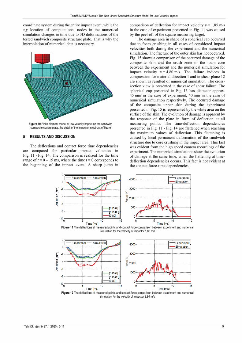
The numerical simulations were modelled in finite element software Abaqus 6.14 using explicit solver and finite strain theory. The computational model was performed as a full contact problem of four bodies – sandwich square plate, impactor and two supports. Eight-node solid elements with reduced integration were applied. The 4 mm approximate global elements size was considered in the case of finite element mesh of sandwich plate, 1,5 mm for the impactor and 10 mm for the supports. The simplification of the impactor was performed in the case of its finite element model and only the spherical head of impactor was modelled. The force sensor cable was neglected. The finite element model is presented in Fig. 10. The friction between bodies and the damping of contact between the impactor and the tested sandwich structure has been neglected. Only the first impact event and the real impact velocities from the experiment listed in Tab. 1 were considered in the case of numerical simulations. The positions of impact points of the impactor and the real impact velocities of the impactor were considered from Tab. 1 in accordance with the performed experiments.
The computed values of deflections at the measuring points from simulations were interpolated from space displacements of neighbouring nodes using bilinear 3D interpolation method. The location of the measuring points of laser sensors is invariable in x,y plane of the global
Tomáš MANDYS et al.: The Non-Linear Sandwich Structure Model for Low-Velocity Impact
Tehnički vjesnik 27, 1(2020), 5-11 9
coordinate system during the entire impact event, while the x,y location of computational nodes in the numerical simulation changes in time due to 3D deformations of the tested sandwich composite structure plate. That is why the interpolation of numerical data is necessary.
Figure 10 Finite element model of low-velocity impact on the sandwich
composite square plate, the detail of the impactor in cut-out of figure 5 RESULTS AND DISCUSSION
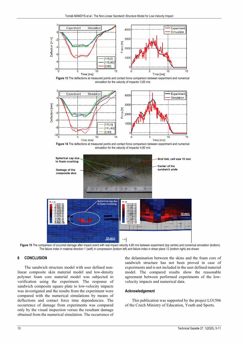
The deflections and contact force time dependencies are compared for particular impact velocities in Fig. 11 - Fig. 14. The comparison is realized for the time range of t = 0 – 15 ms, where the time t = 0 corresponds to the beginning of the impact event. A sharp jump in
comparison of deflection for impact velocity v = 1,85 m/s in the case of experiment presented in Fig. 11 was caused by the peel-off of the square measuring target.
The damage area in shape of a spherical cap occurred due to foam crushing in all cases of considered impact velocities both during the experiment and the numerical simulation. The fracture of the outer skin has not occurred. Fig. 15 shows a comparison of the occurred damage of the composite skin and the crush zone of the foam core between the experiment and the numerical simulation for impact velocity v = 4,80 m/s. The failure indices in compression for material direction 1 and in shear plane 12 are shown as resulted of numerical simulation. The cross-section view is presented in the case of shear failure. The spherical cap presented in Fig. 15 has diameter approx. 45 mm in the case of experiment, 40 mm in the case of numerical simulation respectively. The occurred damage of the composite upper skin during the experiment presented in Fig. 15 is represented by the white area on the surface of the skin. The evolution of damage is apparent by the response of the plate in form of deflection at all measuring points. The time-deflection dependencies presented in Fig. 11 - Fig. 14 are flattened when reaching the maximum values of deflection. This flattening is caused by local permanent deformation of the sandwich structure due to core crushing in the impact area. This fact was evident from the high speed camera recordings of the experiment. The numerical simulations show the evolution of damage at the same time, when the flattening at time-deflection dependencies occurs. This fact is not evident at the contact force-time dependencies.
Figure 11 The deflections at measured points and contact force comparison between experiment and numerical
simulation for the velocity of impactor 1,85 m/s
Figure 12 The deflections at measured points and contact force comparison between experiment and numerical
simulation for the velocity of impactor 2,94 m/s
Tomáš MANDYS et al.: The Non-Linear Sandwich Structure Model for Low-Velocity Impact
10 Technical Gazette 27, 1(2020), 5-11
Figure 13 The deflections at measured points and contact force comparison between experiment and numerical
simulation for the velocity of impactor 3,85 m/s
Figure 14 The deflections at measured points and contact force comparison between experiment and numerical
simulation for the velocity of impactor 4,80 m/s
Figure 15 The comparison of occurred damage after impact event with real impact velocity 4,80 m/s between experiment (top centre) and numerical simulation (bottom).
The failure index in material direction 1 (weft) in compression (bottom left) and failure index in shear plane 12 (bottom right) are shown
6 CONCLUSION
The sandwich structure model with user defined non-linear composite skin material model and low-density polymer foam core material model was subjected to verification using the experiment. The response of sandwich composite square plate to low-velocity impacts was investigated and the results from the experiment were compared with the numerical simulations by means of deflections and contact force time dependencies. The occurrence of damage from experiments was compared only by the visual inspection versus the resultant damage obtained from the numerical simulation. The occurrence of
the delamination between the skins and the foam core of sandwich structure has not been proved in case of experiments and is not included in the user defined material model. The compared results show the reasonable agreement between performed experiments of the low-velocity impacts and numerical data. Acknowledgement
This publication was supported by the project LO1506 of the Czech Ministry of Education, Youth and Sports.

Tomáš MANDYS et al.: The Non-Linear Sandwich Structure Model for Low-Velocity Impact
Tehnički vjesnik 27, 1(2020), 5-11 11
7 REFERENCES [1] Mostafa, A., Shankar, K., & Morozov E.V. (2013). Insight
into the shear behaviour of composite sandwich panels. Materials and Design, 50, 92-101. https://doi.org/10.1016/j.matdes.2013.03.016
[2] Kreculj, D. & Rašuo, B. (2013). Review of impact damages modeling in laminated composite aircraft structures. Technical Gazette, 20(3), 485-495.
[3] Wang, J., Waas, A. M., & Wang, H. (2013). Experimental and numerical study on the low-velocity impact behavior of foam-core sandwich panels. Composite Structures, 96, 298-311. https://doi.org/10.1016/j.compstruct.2012.09.002
[4] Sadílek, P., Zemčík, R., Bartošek, J., & Mandys, T. (2013). Active structural health monitoring of composite plates and sandwiches. Applied and Computational Mechanics, 7, 183-192.
[5] Yhou, J., Guan, Z. W., & Cantwell W. J. (2013). The impact response of graded foam sandwich structure. Composite Structures, 97, 370-377. https://doi.org/10.1016/j.compstruct.2012.10.037
[6] Mamalis, A. G., Spentzes K. N., Papapostolou D. P., & Pantelelis, N. (2013). Finite element investigation of the influence of material properties on the crushing characteristics of in-plane loaded composite sandwich panels. Thin-Walled Structures, 63, 163-174. https://doi.org/10.1016/j.tws.2012.09.011
[7] Kroupa, T., Kunc, K., Zemčík, R., & Mandys T. (2015). The non-linear finite element simulations of tensile tests of textile composites. Materiali in Technologije, 49(4), 509-514. https://doi.org/10.17222/mit.2014.117
[8] Mandys, T., Kroupa, T., & Laš, V. (2014). Progressive failure analysis of composite sandwich beam in case of quasistatic loading. Materiali in Technologije, 48(4), 593-597.
[9] Kroupa, T., Laš, V., & Zemčík, R. (2011). Improved nonlinear stress-strain relation for carbon epoxy composites and identification of material parameters. Journal of Composite Materials, 45(9), 1045-1057. https://doi.org/10.1177/0021998310380285
[10] Ramberg, W. & Osgood, R. (1943). Description of stress-strain curves by three parameters. Technical Note No. 902, NACA - National Advisory Committee for Aeronautics, Washington, DC, U.S.A.
[11] Dassault Systèmes Simulia Corp. (2014), Abaqus 6.14 Documentation, Providence, RI, U.S.A.
[12] Laš, V., Mandys, T., Kroupa, T., & Hynek, R. (2014). Numerical simulation of impact on wide composite sandwich beam. Applied Mechanics and Materials, 611, 162-169. https://doi.org/10.4028/www.scientific.net/AMM.611.162
Contact information: Tomáš MANDYS, PhD (Corresponding author) NTIS – New Technologies for Information Society, Faculty of Applied Sciences, University of West Bohemia, Univerzitní 8, 306 14 Pilsen, Czech Republic [email protected] Tomáš KROUPA, PhD NTIS – New Technologies for Information Society, Faculty of Applied Sciences, University of West Bohemia, Univerzitní 8, 306 14 Pilsen, Czech Republic [email protected] Vladislav LAŠ, Professor NTIS – New Technologies for Information Society, Faculty of Applied Sciences, University of West Bohemia, Univerzitní 8, 306 14 Pilsen, Czech Republic [email protected]