the next generation adaptive optics system - w. m. keck ... proposal... · the next generation...
TRANSCRIPT
The Next Generation Adaptive Optics System at the
W. M. Keck Observatory
A Proposal for Design and Development
June 20, 2006 Final Version
The Next Generation Adaptive Optics System Design and Development Proposal June 20, 2006
-i-
Proposal Editors Sean Adkins, WMKO Rich Dekany, Caltech
Don Gavel, UC Santa Cruz Michael Liu, University of Hawaii
Franck Marchis, UC Berkeley Claire Max, UC Santa Cruz
Chris Neyman, WMKO Peter Wizinowich, WMKO
Solar System Science
Máté Ádámkovics, Antonin Bouchez, Joshua Emery, Franck Marchis (chair), Keith Noll
Galactic Science
Andrea Ghez, Tom Greene, Lynne Hillenbrand, Michael Liu (chair), Jessica Lu, Bruce Macintosh,
Stanimir Metchev, Nevin Weinberg
Extragalactic Science Mark Ammons, Aaron Barth, Rich Dekany,
Don Gavel, David Koo, Patrik Jonsson, David Law, James Larkin, Claire Max (chair), Laura Melling, Greg Novak, Chuck Steidel,
Tommasu Treu
Technical Sean Adkins, Brian Bauman, Jim Bell,
Antonin Bouchez, Rich Dekany, Ralf Flicker, Don Gavel, Olivier Lai, Bruce Macintosh, Keith Matthews,
Chris Neyman, Viswa Velur, Peter Wizinowich (chair)

The Next Generation Adaptive Optics System Design and Development Proposal June 20, 2006
Table of Contents
-ii-
1 Abstract..................................................................................................................................... 1 2 Introduction.............................................................................................................................. 3
2.1 A Next Generation AO System for the Keck Observatory................................................ 3 2.2 Recent History and Planning ............................................................................................. 4 2.3 The Competitive Landscape .............................................................................................. 6
2.3.1 Background................................................................................................................ 6 2.3.2 Gemini Observatory................................................................................................... 6 2.3.3 European Southern Observatory ................................................................................ 7 2.3.4 Subaru ........................................................................................................................ 7 2.3.5 LBT............................................................................................................................ 8 2.3.6 Summary .................................................................................................................... 9
2.4 Science with the Existing Keck AO Systems .................................................................... 9 3 Science Case............................................................................................................................ 12
3.1 Introduction...................................................................................................................... 12 3.2 Solar System Science....................................................................................................... 12
3.2.1 Introduction.............................................................................................................. 12 3.2.2 Multiplicity in the Asteroid Populations.................................................................. 13 3.2.3 Size and Shape of Asteroids .................................................................................... 20 3.2.4 Moonlet Spectroscopy ............................................................................................. 25 3.2.5 Titan – The coupled surface-atmosphere system with NGAO ................................ 29 3.2.6 Study of Io volcanic activity .................................................................................... 34 3.2.7 Conclusion ............................................................................................................... 38
3.3 Galactic Science............................................................................................................... 39 3.3.1 Introduction.............................................................................................................. 39 3.3.2 Diffraction-Limited Imaging of Protostellar Envelopes and Outflows ................... 40 3.3.3 Imaging and Characterization of Extrasolar Planets................................................ 44 3.3.4 Next-Generation Debris Disk Science ..................................................................... 49 3.3.5 The Galactic Center: Black Holes, General Relativity, and Dark Matter................ 55
3.4 Extragalactic Science ....................................................................................................... 61 3.4.1 Introduction.............................................................................................................. 61 3.4.2 High-Redshift Galaxies and Mergers....................................................................... 62 3.4.3 Strong Gravitational Lensing................................................................................... 75 3.4.4 Active Galactic Nuclei and Black Holes ................................................................. 83
3.5 Science Requirements...................................................................................................... 90 3.5.1 Solar System Science............................................................................................... 90 3.5.2 Galactic Science....................................................................................................... 91 3.5.3 Extragalactic Science ............................................................................................... 92 3.5.4 Summary of Science Requirements ......................................................................... 93
4 Technical................................................................................................................................. 97 4.1 Introduction...................................................................................................................... 97 4.2 Requirements ................................................................................................................... 98

The Next Generation Adaptive Optics System Design and Development Proposal June 20, 2006
Table of Contents
-iii-
4.2.1 Science Requirements Flow Down.......................................................................... 98 4.2.2 Observatory Requirements..................................................................................... 101 4.2.3 Mauna Kea Site Conditions ................................................................................... 102
4.3 Point Design................................................................................................................... 103 4.3.1 Point Design Overview.......................................................................................... 103 4.3.2 Point Design Performance versus Requirements................................................... 108 4.3.3 Point Design Subsystems....................................................................................... 123
4.4 System Design Technical Approach.............................................................................. 136 5 Management ......................................................................................................................... 139
5.1 Introduction.................................................................................................................... 139 5.2 Project Plan and Schedule.............................................................................................. 139 5.3 System Design ............................................................................................................... 143
5.3.1 System Design Deliverables .................................................................................. 143 5.3.2 System Design Plan ............................................................................................... 144
5.4 Risk Assessment and Risk Management Plan ............................................................... 146 6 Budget ................................................................................................................................... 147
6.1 System Design Phase ..................................................................................................... 147 6.2 Preliminary and Detailed Design through Full Scale Development.............................. 148 6.3 Science Instruments ....................................................................................................... 149 6.4 Operations ...................................................................................................................... 150
7 Appendix. The Global Landscape for Next Generation AO Systems............................. 151 8 Appendix. Number of Observable Asteroids .................................................................... 152 9 Appendix. Satellites of Giant Planets Observable with NGAO....................................... 153 10 Appendix. Observatory Requirements .............................................................................. 154 11 Appendix. Requirements Document .................................................................................. 157
11.1 Performance Requirements............................................................................................ 157 11.2 Implementation Requirements ....................................................................................... 159 11.3 Design Requirements ..................................................................................................... 159
12 Appendix. Components and Component Technology ...................................................... 161 12.1 Wavefront Sensing......................................................................................................... 161
12.1.1 Laser guide star high-order WFS........................................................................... 161 12.1.2 Natural guide star high-order WFS........................................................................ 162 12.1.3 Low-order WFS – visible....................................................................................... 163 12.1.4 Low-order WFS – infrared TT/FA ........................................................................ 163 12.1.5 Calibration/Truth WFS .......................................................................................... 163
12.2 Wavefront Correction .................................................................................................... 164 12.2.1 Deformable mirrors................................................................................................ 164
12.3 Tip/Tilt Control.............................................................................................................. 166 12.4 Metrology....................................................................................................................... 166 12.5 Real-time Controller ...................................................................................................... 166
12.5.1 Real-time control requirements.............................................................................. 166

The Next Generation Adaptive Optics System Design and Development Proposal June 20, 2006
Table of Contents
-iv-
12.5.2 Architecture and algorithms................................................................................... 167 12.5.3 Estimate of processor requirements ....................................................................... 171 12.5.4 Diagnostic and Telemetry Streams ........................................................................ 173
12.6 Laser Guide Star Facility ............................................................................................... 173 12.6.1 Requirements ......................................................................................................... 173 12.6.2 Laser technology.................................................................................................... 175 12.6.3 Transport options ................................................................................................... 177
12.7 References...................................................................................................................... 178 13 Appendix. AO System Key Features................................................................................. 179 14 Appendix. Wavefront Error Budget ................................................................................. 184
14.1 Example: Narrow-field science with LGS and tip/tilt NGS stars (KBO science program) 184 14.2 Wavefront Error Budget Summaries ............................................................................. 188
15 Appendix. Wavefront Error Budget Terms ...................................................................... 193 16 Appendix: Point Spread Function Simulations................................................................. 201
16.1 Introduction.................................................................................................................... 201 16.2 Linear Adaptive Optics Simulator Code........................................................................ 201
16.2.1 Tomography:.......................................................................................................... 201 16.2.2 Atmospheric model and propagation:.................................................................... 202 16.2.3 DM and WFS models............................................................................................. 202 16.2.4 Segmented telescope primary (M1) ....................................................................... 203
16.3 Simulations for NGAO science case.............................................................................. 203 16.3.1 Simulation of narrow field of view AO, on axis PSF............................................ 203 16.3.2 High contrast simulations ...................................................................................... 205 16.3.3 Seeing variability simulations................................................................................ 206
16.4 Future simulations.......................................................................................................... 206 Appendix: System Design Phase Trade Studies........................................................................ 207 17 Appendix. Risk Assessment and Mitigation Plans............................................................ 216

The Next Generation Adaptive Optics System Design and Development Proposal June 20, 2006
Figures and Tables
-v-
Figure 1 Strehl versus wavelength as a function of rms wavefront error. ......................................... 5 Figure 2 Expenditures and future plans for adaptive optics for ESO and for the US........................ 9 Figure 3 Keck AO science papers by year and type of science. ...................................................... 10 Figure 4 TAC-Allocated NGS and LGS AO science nights in semesters 06A and 06B................. 10 Figure 5 First triple asteroidal system 87 Sylvia and its two moonlets, Romulus and Remus........ 15 Figure 6 Pseudo-87 Sylvia simulated. ............................................................................................. 18 Figure 7 Simulation of pseudo- Sylvia observed with various AO systems.................................... 18 Figure 8 Typical spectra of an asteroid with a mafic companion. ................................................... 27 Figure 9 Simultaneous H- and K-band images of Titan from the ground (Ádámkovics et al., 2006).
.................................................................................................................................................. 31 Figure 10 Validation of simulation with observations along with examples of expected NGAO
performance. ............................................................................................................................ 31 Figure 11 Titan in J band observed with NGAO (140 nm error) with an angular resolution of 25
mas. The yellow area shows the fluvial feature that can be resolved with NGAO. ................ 32 Figure 12 Simulation of resurfacing on Titan at the 100km scale, due to cryovolcanic release of
bright material.......................................................................................................................... 33 Figure 13 Io observed by Galileo/SSI (visible camera). Surface features on the disk and plumes at
the limb related to the active volcanism can be observed........................................................ 35 Figure 14 Simulated observations of Io in sunlit using the Keck NGAO (140 nm) in various filters.
.................................................................................................................................................. 37 Figure 15 R-band observation simulation of Io (angular diameter of 0.9”) with KNGAO and
HST/ACS. ................................................................................................................................ 38 Figure 16 Seeing-limited (0.5-0.6”) I-band (0.8 μm) images of protostars in Taurus-Auriga ........ 41 Figure 17 Integrated-light SEDs. ..................................................................................................... 42 Figure 18 Simulated I-band images for a model of the circumstellar dust around a Class I object at
a distance of 1 kpc.................................................................................................................... 43 Figure 19 JHK color image of the 2MASS 1207-3932 system. ...................................................... 46 Figure 20 Planet detection sensitivity for Keck NGAO for two different primary masses and ages.
.................................................................................................................................................. 47 Figure 21 Schematic comparison of the relative parameter space for direct imaging of planets. ... 48 Figure 22 The HR 4796A (Schneider et al 1999) and AU Mic (Liu 2004) debris disks................. 50 Figure 23 Simulated H-band images of two variants of the Keck NGAO system compared to the
present-day Keck AO system................................................................................................... 51 Figure 24 Required astrometric precision for detecting GR effects. ............................................... 57 Figure 25 Error contours for BH mass and GC distance. ................................................................ 58 Figure 26 Map of tip-tilt blurring, in mas, in the GOODS-North, GOODS-South, and part of the
COSMOS deep fields............................................................................................................... 65 Figure 27 Signal to noise ratio for an OSIRIS-like IFU with NGAO. ............................................ 66 Figure 28 Computer simulation of imaging and spectroscopy of the z ~ 2 galaxy BX 1332 from the
catalog of Erb et al. (2004). ..................................................................................................... 67

The Next Generation Adaptive Optics System Design and Development Proposal June 20, 2006
Figures and Tables
-vi-
Figure 29 Section of 40” x 40” of the GOODS North (left) and South (right) fields...................... 69 Figure 30 An R-band image (with radio isophotes overlaid) of the field surrounding the ULIRG
FF0240-0042............................................................................................................................ 69 Figure 31: Improvements in SNR and velocity measurements with NGAO................................... 71 Figure 32 Typical angular scales of cluster-size lensing and galaxy-size lensing........................... 76 Figure 33 Searching for multiple images......................................................................................... 78 Figure 34 Simulated observations of a gravitational lens................................................................ 80 Figure 35 Reconstructed 68% and 95% confidence contours for the source parameters, from a
Markov Chain Monte Carlo algorithm. ................................................................................... 81 Figure 36 Minimum detectable black hole mass as a function of galaxy distance.......................... 85 Figure 37 Simulated K-band measurement of the rotation curve of an early-type galaxy with a
super massive black hole. ........................................................................................................ 88 Figure 38 Simulated K' observation of a z = 2 quasar with current LGS AO and with NGAO...... 89 Figure 39 Schematic of NGAO Architecture................................................................................... 98 Figure 40 Point Design: Zemax optical layout on the Nasmyth platform. .................................... 104 Figure 41 NGAO system on the Keck left Nasmyth platform....................................................... 105 Figure 42 Point Design: Dichroic Switchyard ............................................................................... 106 Figure 43 Point Design: NGAO transmitted field showing LGS asterism, NGS and science field.
................................................................................................................................................ 107 Figure 44 Point Design: DM actuators and WFS subapertures projected onto the Keck telescope
pupil. ...................................................................................................................................... 107 Figure 45 Multi-guidestar AO processing architecture ................................................................. 108 Figure 46 Background in the K band due to point design NGAO system..................................... 109 Figure 47 NGAO point design performance vs KBO brightness b = 30° and zenith angle = 30° in
median seeing......................................................................................................................... 111 Figure 48 NGAO point design Galactic Center performance versus seeing conditions, using IRS7
as the tip/tilt/focus star. .......................................................................................................... 112 Figure 49 Deployable IFU H-band performance versus sky fraction, for different zenith angles.
Note that a better figure of merit is enclosed energy for a d-IFU.......................................... 113 Figure 50 Image width entering d-IFU versus sky fraction, for actual GOODS-N field and 45°
zenith angle. ........................................................................................................................... 114 Figure 51 High order Strehl as a function of zenith angle. ............................................................ 115 Figure 52: Comparison of different sources of scattered light. ..................................................... 121 Figure 53: Comparison of the effects of static wavefront errors on NGAO high-contrast
performance. .......................................................................................................................... 122 Figure 54: Effects of residual segment aberrations on contrast. .................................................... 122 Figure 55 NGAO Major System Categories.................................................................................. 123 Figure 56 Major AO Subsystems................................................................................................... 124 Figure 57 Major Laser Subsystems................................................................................................ 127 Figure 58 Major Operations Tools Categories............................................................................... 128
The Next Generation Adaptive Optics System Design and Development Proposal June 20, 2006
Figures and Tables
-vii-
Figure 59 Top-Level WBS............................................................................................................. 140 Figure 60 Project Plan showing WBS and schedule...................................................................... 142 Figure 61 System Design Phase Plan showing WBS and Schedule.............................................. 145 Figure 62 Conceptual block diagram of the Keck NGAO MCAO/MOAO architecture. ............. 161 Figure 63 Multi-guidestar AO processing architecture ................................................................. 167 Figure 64 Example error budget tree for KBO science case. ........................................................ 185 Figure 65 Error budget summary for LGS mode having an on-axis tip/tilt reference source. ...... 187 Figure 66 "Best conditions" narrow field case. ............................................................................. 188 Figure 67 Io case............................................................................................................................ 189 Figure 68 Galactic Center case. ..................................................................................................... 190 Figure 69 Field Galaxies case. ....................................................................................................... 191 Figure 70 GOODS-N case. ............................................................................................................ 192 Figure 71 Grid of 120 nm PSF from LAOS simulations. .............................................................. 205
The Next Generation Adaptive Optics System Design and Development Proposal June 20, 2006
Figures and Tables
-viii-
Table 1 Next-generation AO systems under development for 8-10 meter telescopes....................... 8 Table 2 Number of asteroids observable using the NGAO system. ................................................ 16 Table 3 Detection rate and photometry on the moons of pseudo-Sylvia. ........................................ 19 Table 4 Number of asteroids resolvable with Keck NGAO in various wavelength ranges and per
population. ............................................................................................................................... 24 Table 5 S/N on the spectra estimated of Pseudo Sylvia moons with 1h exposure time. ................. 28 Table 6 Space Densities of Various Categories of Extragalactic Targets. ...................................... 63 Table 7 Fractional sky coverage into IFU spaxels of three different sizes for four "deep fields,"
assuming that the galaxy contains point-like substructure. ..................................................... 64 Table 8 Preliminary NGAO science requirements, with yellow showing the key drivers. ............. 94 Table 9 Summary of overall AO concept requirements by science area. ........................................ 95 Table 10 Summary of instrument priorities by major science areas................................................ 96 Table 11 Mauna Kea Cn2 Profile. ................................................................................................. 102 Table 12 Emissivity and temperature of each element in the IR science path. ............................. 110 Table 13 NGAO point design performance summary for several key science cases. ................... 110 Table 14: Estimated limiting magnitudes. ..................................................................................... 117 Table 15 Definition of terms used in processing calculation......................................................... 124 Table 16 Image Processor steps..................................................................................................... 125 Table 17 Tomography Unit processing steps................................................................................. 125 Table 18 DM Projection and Fitting processing steps. .................................................................. 126 Table 19: NGAO instrument priorities. ......................................................................................... 130 Table 20: Basic Requirements for the Visible Imager................................................................... 132 Table 21: Basic Requirements for the Near-IR Imager ................................................................. 132 Table 22: Basic Requirements for the Thermal near-IR Imager.................................................... 133 Table 23: Notional requirements for the near-IR IFU ................................................................... 134 Table 24: Notional requirements for the Visible IFU.................................................................... 135 Table 25: Notional requirements for each unit of the near-IR deployable IFU............................. 136 Table 26 Very Rough Initial Budget Estimate (07 dollars) for Preliminary Design through
Commissioning. ..................................................................................................................... 149 Table 27; ROM COST Estimates for NGAO Instrumentation...................................................... 150 Table 28 Instruments for use with AO systems ............................................................................. 151 Table 29 Satellites of giant planets observable with NGAO. ........................................................ 153 Table 30 Performance Budgets...................................................................................................... 157 Table 31 Specifications for high order LGS wavefront sensors .................................................... 161 Table 32 Detectors for high order wavefront sensors.................................................................... 162 Table 33 Specifications for high speed low order wavefront sensors ........................................... 163 Table 34 Truth wavefront sensor specifications ............................................................................ 164 Table 35 Piezo deformable mirror for Keck NGAO ..................................................................... 164 Table 36 MEMS deformable mirror for K-NGAO........................................................................ 165

The Next Generation Adaptive Optics System Design and Development Proposal June 20, 2006
Figures and Tables
-ix-
Table 37 Deformable mirror technology status ............................................................................. 165 Table 38 Real time control specifications for Keck NGAO.......................................................... 166 Table 39 Definition of symbols ..................................................................................................... 168 Table 40 Processing steps from Hartmann slopes to wavefront phase.......................................... 169 Table 41 Tomography processing steps......................................................................................... 169 Table 42 Deformable mirror real time processing steps................................................................ 170 Table 43 Estimated compute power requirements for NGAO real-time processing ..................... 172 Table 44 Laser Beacon Requirements ........................................................................................... 173 Table 45 Sodium laser technology in use in astronomical adaptive optics systems. The latter two in
this list are under development through the NSF/NOAO Adaptive Optics Development program. ................................................................................................................................. 175
Table 46 The various terms used in the current point design error budget for NGAO. ................ 204

The Next Generation Adaptive Optics System Design and Development Proposal June 20, 2006
-1-
1 ABSTRACT
The Keck telescopes are the world’s largest optical and infrared telescopes. Because of their large apertures the Keck telescopes offer the highest potential sensitivity and angular resolution currently available. Unfortunately, without a means to overcome the performance limits imposed by the turbulence of the earth’s atmosphere much of the superiority of the Keck telescopes would remain unrealized. Adaptive optics (AO) is now an established and fundamental technique for overcoming the performance limiting effects of atmospheric turbulence. The W. M. Keck Observatory has been among the leaders in the application of AO and the importance of achieving the full potential of the Keck telescopes is recognized in the Observatory’s strategic plan which identifies leadership in high angular resolution astronomy as a key long-term goal. At this time we face a number of challenges to our leadership in high angular resolution astronomy because of the aggressive development efforts in AO that are being carried out by the world’s other large telescope observatories. In order to maintain our leadership we must pursue new AO systems and the instrumentation to exploit them. Our consideration of the competitive landscape has found that there are major opportunities for the Observatory to assert its continued leadership through an ambitious program that will address clearly differentiable and unique objectives for AO on the Keck telescopes. Over the past six months we have examined a broad range of key science areas in order to identify the most compelling future science goals of our community and to determine what is needed to realize these goals. As a result we propose to begin the design phase of a next generation adaptive optics (NGAO) system that will provide a powerful new suite of capabilities:
• Near diffraction-limited performance at infrared wavelengths, producing an AO point spread function with unprecedented precision, stability and contrast;
• Vastly increased sky coverage and multiplexing capability, enabling a much broader range of science programs; and
• AO correction into the red portion of the visible spectrum (0.6-1.0 µm), delivering the highest angular resolution images available from any filled aperture telescope.
The proposed concept will be a broad and powerful facility with the potential to achieve major advances in astrophysics. NGAO will provide dramatic gains in solar system and galactic science where AO has already demonstrated a strong scientific impact. NGAO will allow for extraordinary advances in extragalactic astronomy, far beyond the initial gains being made now with the Observatory’s current AO systems. Our proposal lays out a point-design for implementing the NGAO system, and outlines a series of technical studies and cost-benefit trades that will be completed in the next phase of system design. It also describes a proposed suite of instruments, with highest priority given to narrow-field near

The Next Generation Adaptive Optics System Design and Development Proposal June 20, 2006
-2-
infrared and visible imagers, and to a near-infrared deployable integral field spectrograph with multi-object capability. The proposed NGAO system is similar in concept, but notably less sweeping in scope, to systems proposed for the Thirty Meter Telescope (TMT). As such it will benefit from the feasibility studies already completed and being conducted for the TMT. Moreover, by implementing NGAO at least several years ahead of analogous TMT instruments, our community will gain both scientific and technical experience that can materially help future TMT efforts. The success of the current laser guide star AO system at the Observatory is just a hint of the benefits that will accrue from the continued development of AO. A next generation AO system will be a technically challenging project with significant funding requirements. It would be easy to conclude that the level of risk is too high, and that we should find ways to keep pace with the advancing technology of astronomy in fields other than AO. However, the benefits to science from an ambitious development in AO are tremendous, and these developments are the key to realizing the full potential of the Keck telescopes. Beginning the process of developing AO capability suited to the broad range of high impact scientific problems discussed in this proposal could be the best and most important way to secure the future of the Observatory and our community.
The Next Generation Adaptive Optics System Design and Development Proposal June 20, 2006
-3-
2 INTRODUCTION
The twin 10 m Keck telescopes were the first of a new generation of ground-based, large optical/infrared telescopes, offering major improvement in light gathering power and angular resolution. A 2002 Visiting Committee of distinguished U.S. astronomers, reviewing the performance and standing of the Observatory, wrote: “The Keck Observatory has dominated ground-based...astronomy for a decade. It is scientifically extremely productive.” Keck has continued its lead by being the first to implement both natural guide star (NGS) and laser guide star (LGS) adaptive optics (AO) systems in order to achieve angular resolutions that match the visible light capabilities of the Hubble Space Telescope. Nearly 100 refereed science papers have been produced using the Keck AO systems. The WMKO 2002 Strategic Planning Workshop identified “Maintaining world leadership in high angular resolution astronomy” as a 20-year strategic goal paramount to the Observatory’s mission. In this proposal we describe how we plan to implement the next major step toward this vision by providing a next generation AO (NGAO) system with dramatically increased scientific capabilities. Section 2.1 provides a brief overview of the NGAO proposal. In the remainder of this introduction we provide some of the background context that has led us to recommend the NGAO system in this proposal. This context includes a summary of the AOWG discussions that led to this recommendation (section 2.2). We then review the competitive landscape (section 2.3) and the impact of our existing AO systems on science and education (2.4). All of these elements have contributed to the scientific case for the proposed NGAO system. 2.1 A Next Generation AO System for the Keck Observatory
We propose to study the feasibility of a Next Generation Adaptive Optics (AO) system for the Keck Observatory. This new system will build upon Keck’s current leadership in high-spatial-resolution laser guide star (LGS) AO. It will provide substantially higher Strehl ratios in the near infrared and, for the first time, good AO correction in R, I, and z-bands. It will have unique capability for extragalactic astrophysics, through a multi-object AO system that feeds deployable integral field units (IFUs). The latter take advantage of MEMS deformable mirror (DM) development at the Center for Adaptive Optics and of the demonstrated capabilities of AO integral field spectroscopy through the facility instrument OSIRIS, and paves the way for its analog on the Thirty Meter Telescope. In this proposal we present a powerful science case for the Next Generation AO system (NGAO), derive the science requirements, describe a point design capable of fulfilling these requirements, and outline instrument concepts that would take full advantage of NGAO. In the coming year we propose to begin the design development phase by doing a feasibility study that deepens our understanding of the science requirements; explores trade studies between the AO system, instrument designs, and science case; and brings us to the System Design Review stage. During the coming year we will develop modular options for potential funding of the new AO system and

The Next Generation Adaptive Optics System Design and Development Proposal June 20, 2006
-4-
its instrumentation suite, identify specific packages suitable for funding by separate donors and agencies, and outline scenarios for phased funding. The proposed new AO system will give Keck a genuinely unique role within the next-generation systems under development in the rest of the world. While ESO, Gemini, and other 8 – 10 m telescopes are devoting very generous funding to extreme AO planet-finding systems and to wide-field ground-layer AO systems for seeing improvement, none are yet occupying the niche which we find most compelling scientifically: “precision AO” that takes full advantage of Keck’s larger aperture, and that effectively multiplies that aperture for multi-object work through use of deployable IFUs. 2.2 Recent History and Planning
The precision AO approach we propose here has a strong heritage within the Keck Adaptive Optics Working Group (AOWG) strategic planning process. In November 2002, the Keck AOWG completed a strategic plan for future AO systems at the Observatory. This plan was subsequently approved by the Science Steering Committee in 2003. The plan was reaffirmed and an updated version was issued by the AOWG in September 2004 (KAON 271). We are now in 2006, and the first three vital areas of the strategic plan have been successfully completed: the Keck II AO system has been optimized, the laser guide star is in science operation, and OSIRIS has been commissioned. The LGS and OSIRIS, working together, are leading the world at the moment. A fourth component of the strategic plan, the Next-Generation Wavefront Controller upgrade, is also going very well: commissioning is scheduled for late 2006 on Keck I and early 2007 on Keck II. The new wavefront controller will increase sensitivity to faint guide stars by at least one magnitude, and will replace obsolete components so as to give robust AO operations on both telescopes for the coming five to ten years. The fifth component of the 2002 strategic plan, an extreme AO planet-finder for Keck, has not come to pass. Instead this instrument is now funded by Gemini and will be installed at the Gemini South Telescope. Subsequent to preparation of the AOWG strategic plan in 2002, the National Science Foundation awarded funding for a solid-state laser guide star on Keck I. The infrastructure for this laser is currently being designed, and the laser is scheduled for delivery to Keck in mid-2007. Following laser commissioning, OSIRIS will be moved to Keck I to provide laser guide star AO capability at both telescopes starting in 2008 (NIRC2 will remain on Keck II). The sixth and final part of the 2002 strategic plan was development of a new AO facility called Keck Precision Adaptive Optics System (KPAO). While in 2002 there was not yet a specific

The Next Generation Adaptive Optics System Design and Development Proposal June 20, 2006
-5-
hardware concept for this new system, it was envisioned to provide substantially higher Strehl performance in the near infrared as well as good AO correction in the visible, perhaps even down to the wavelength of Hα. Figure 1 compares the predicted Strehl performance versus wavelength for a next generation system to that of the current Keck AO system (NGS 250 nm and LGS 400 nm). The NGAO system discussed in this proposal has predicted rms wavefront errors typically in the 120 to 180 nm range depending on the observation being performed. Approximately one Keck FTE per year and part of a post-doc’s time has been allocated to fleshing out the KPAO concept since the start of FY05.
Figure 1 Strehl versus wavelength as a function of rms wavefront error.
In the fall of 2005 the AOWG and the Science Steering Committee decided that it was time to look into potential future Keck AO systems in a more intensive manner. To accomplish this goal, the AOWG and the WMKO AO group jointly assembled a science team and a technical working group, which have been working together to develop the science case and point design for Next Generation AO at Keck. The current proposal is the outcome of this six-month effort.

The Next Generation Adaptive Optics System Design and Development Proposal June 20, 2006
-6-
2.3 The Competitive Landscape
2.3.1 Background
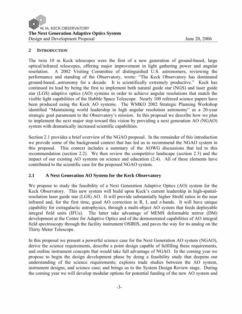
A key component of any strategic planning exercise is to identify the competitive landscape, and to use this global perspective to focus on opportunities for future projects. To accomplish this, the NGAO team (science plus technical working groups) did a broad survey of current and future AO systems worldwide. Within the scope of our science goals we aim to position Keck NGAO to take a global leadership role in AO, rather than building the second or third or fourth version of a specific type of next-generation AO system. We found that the VLT and Gemini Observatories are planning on Ground Layer AO and Extreme AO. Gemini South and (eventually) the LBT plan to have MCAO systems. By contrast precision AO, which has been the AOWG’s goal for the past four years, has been neglected in the plans of the other 8-10 meter telescopes. This leaves an important and exciting competitive niche which Keck NGAO is well-poised to exploit. We shall report in Section 3 of this proposal that precision AO enables a compelling science case for the Keck community. The full result of our survey of planned AO science instruments is found in the Appendix. The Global Landscape for Next Generation AO Systems. In Table 1 we give an overview of plans of other observatories for what we call “next-generation AO systems” on 8-10 m telescopes. By next-generation AO we mean those systems that go beyond single-conjugate AO with one laser guide star, or that aim for a special-purpose application such as high-contrast imaging or interferometry. We obtained our information from published papers, web sites, and the May 2006 SPIE meeting in Orlando FL. 2.3.2 Gemini Observatory
Gemini has three ambitious new AO systems and two new AO-dedicated instruments under development and/or study:
• Near-IR Coronagraphic Imager (NICI): The observatory is commissioning a high contrast instrument in Fall 2006, consisting of an 85-element curvature AO system and a dual-channel imager tuned to detecting ultracool substellar objects. Gemini is planning an ambitious 2-3 year dedicated observing campaign with NICI with the goal of direct imaging and characterization of giant planets around the nearest young stars.
• Gemini Planet Imager: The observatory has funded a very ambitious extreme adaptive optics project called the Gemini Planet Imager (PI: Bruce Macintosh, LLNL). This $24M endeavor consists of an adaptive optics system with about 1800 active degrees of freedom, a coronagraph, and a low spectral resolution IFU (PI: James Larkin, UCLA). It is aimed at detecting giant planets around young stars.

The Next Generation Adaptive Optics System Design and Development Proposal June 20, 2006
-7-
• MCAO with Dedicated IR Imager: Gemini has funded and is close to installing its multi-conjugate AO system (MCAO) on Gemini South. This system will have 5 laser guide stars and a 2 arc min field of view. Its back-end instrument is GSAOI, the Gemini South AO Imager; this is a 2 arc min near-infrared imager built by Australian National University.
• GLAO: Gemini has completed a feasibility study for a Ground Layer AO system (Herzberg Institute of Astrophysics, Durham University, and University of Arizona). The intended completion date is not yet clear.
2.3.3 European Southern Observatory
The VLT has embarked on an impressive long-term plan for adaptive optics that includes three new AO systems, a new laser facility, and five new AO-fed instruments:
• SPHERE, the VLT planet-finder. This is a high-order AO system with three different back-end instruments (a differential imager, an integral field spectrograph, and a visible-red coronagraph
• The “AO Facility,” a four-laser-guide-star facility feeding two different AO systems, and using a new 1170-actuator adaptive secondary (description of AO systems follows)
• GRAAL, a ground-layer AO system that sends light to the new wide-field HAWK-I infrared imager (7.5 arc min field of view)
• GALACSI, a ground-layer AO system that sends light to the new MUSE instrument (this remarkable instrument consists of 24 visible-light IFUs, each with a 1 arc min field of view)
2.3.4 Subaru
Subaru is replacing its previous AO system and dye laser with a higher-order system aimed at high-contrast imaging. This is a 188 degree of freedom curvature system (the largest such system ever built) together with a new 4 watt solid-state sum-frequency laser. The new instrument that will utilize this LGS AO system is Hi-CIAO, a near-IR coronagraphic imager.
The Next Generation Adaptive Optics System Design and Development Proposal June 20, 2006
-8-
Table 1 Next-generation AO systems under development for 8-10 meter telescopes.
Next-Generation AO Systems Under Development for 8 - 10 meter Telescopes
Type Telescope GS Next-Generation AO Systems for 8 to 10 m
telescopes Capabilities Operations
Date
High-contrast Gemini-S NGS Near-IR Coronagraphic Imager (NICI)
Good Strehl, 85-act curvature, dual-channel imager 2006
High-contrast Subaru N/LGS Coronagraphic Imager (CIAO)
Good Strehl, 188-act curvature, 4W laser 2007
High-contrast VLT NGS Sphere (VLT-Planet Finder)
High Strehl; not as ambitious as GPI 2010
High-contrast Gemini-S NGS Gemini Planet Imager (GPI) Very high Strehl 2010
Wide-field Gemini-S 5 LGS MCAO 2’ FOV 2007
Wide-field Gemini 4 LGS GLAO Feasibility Study Completed ?
Wide-field VLT 4 LGS HAWK-I (near IR imager) + GRAAL GLAO
7.5' FOV, AO seeing reducer, 2 x EE in 0.1'' 2012
Wide-field VLT 4 LGS MUSE (24 vis. IFUs) + GALACSI GLAO
1' FOV; 2 x EE in 0.2" at 750nm 2012
Narrow-field VLT 4 LGS MUSE (24 vis. IFUs) + GALACSI GLAO
10” FOV, 10% Strehl @ 650 nm 2012
Interferometer LBT NGS AO for LINC-NIRVANA (IR interferometer)
Phase 1: Single conj., 2 tel’s Phase 2: MCAO 1 telescope
Phase 3: MCAO both telescopes
Phase 1 in 2008
2.3.5 LBT
The LBT’s main AO system is LINC-NIRVANA, and feeds the infrared interferometer. In its first phase it will provide single-conjugate AO to both telescopes, using two adaptive secondaries. In the second phase an MCAO system will be added to one of the telescopes. In the third phase both telescopes will get MCAO systems.

The Next Generation Adaptive Optics System Design and Development Proposal June 20, 2006
-9-
2.3.6 Summary
Overall, ESO’s investments in ambitious AO projects and multiple AO-fed instruments makes it the most formidable competitor for Keck in the coming decade. Figure 2, compiled by J. Frogel of AURA, illustrates this graphically. In addition to its higher level of funding, Europe’s depth and breadth in AO-trained engineers and astronomers are no less impressive. We believe the message of Figure 2 is that we should not shy away from being technologically ambitious, and indeed that we must be clever and courageous if Keck is going compete successfully with ESO in the future. The proposed NGAO system for Keck fulfills both of these criteria. NGAO will provide very substantial improvements in science capability, and will compete in a niche (precision AO) in which neither ESO nor Gemini has current plans for investment.
Figure 2 Expenditures and future plans for adaptive optics for ESO and for the US. 2.4 Science with the Existing Keck AO Systems
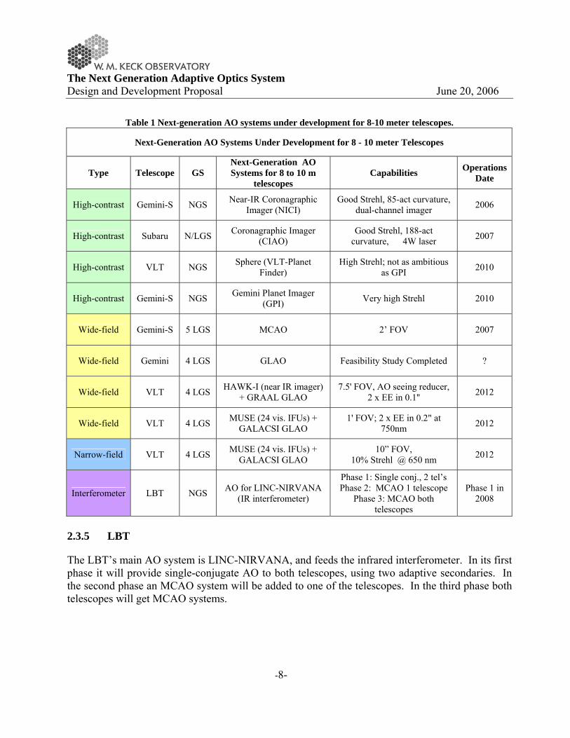
The Keck AO systems, both with and without laser guide star, have been extremely fruitful. Through May 2006 a total of 98 refereed science papers have been accepted for publication based on Keck AO data. The distribution with respect to subfield is as follows: 32% solar system, 52% galactic and 16% extragalactic as shown in Figure 3; this total includes nine papers from the Keck Interferometer. A total of 13 LGS science papers have been published or accepted beginning in 2005 (23% solar system, 46% galactic and 31% extragalactic).
The Next Generation Adaptive Optics System Design and Development Proposal June 20, 2006
-10-
2000 2001 2002 2003 2004 2005 2006
Solar SystemGalactic
Extra-galactic0
2
4
6
8
10
12
14N
umbe
r of P
aper
s
Year
Refereed Keck AO Science Papers by Year
Figure 3 Keck AO science papers by year and type of science.
0
5
10
15
20
25
LGS (06A) NGS (06A) LGS (06B) NGS (06B)
Num
ber
of N
ight
s
Solar SystemGalacticExtragalactic
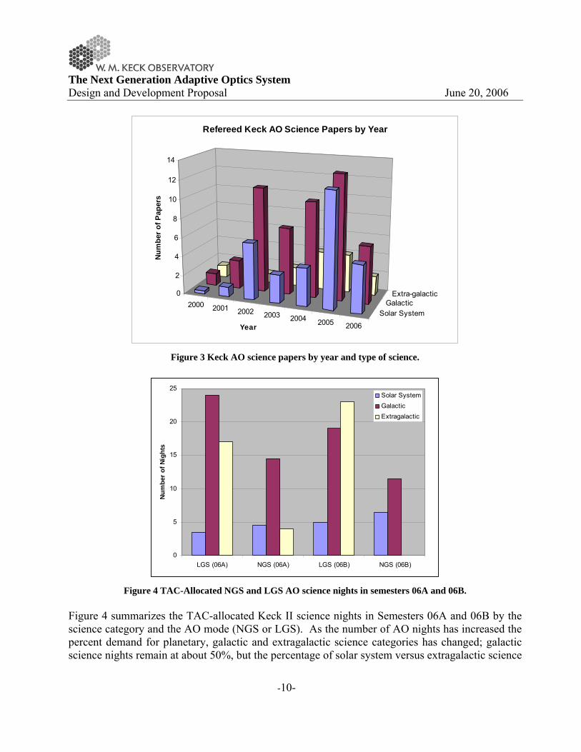
Figure 4 TAC-Allocated NGS and LGS AO science nights in semesters 06A and 06B.
Figure 4 summarizes the TAC-allocated Keck II science nights in Semesters 06A and 06B by the science category and the AO mode (NGS or LGS). As the number of AO nights has increased the percent demand for planetary, galactic and extragalactic science categories has changed; galactic science nights remain at about 50%, but the percentage of solar system versus extragalactic science
The Next Generation Adaptive Optics System Design and Development Proposal June 20, 2006
-11-
nights has switched in favor of extragalactic science. The demand for NIRC2 and OSIRIS is roughly equal, with modest demands for NIRSPEC and the Interferometer. The demand for LGS AO mode is very high although a significant number of NGS nights are still requested. Keck AO has had a significant impact on the young researchers in our community. A rough count was made of student participation in the author lists of the Keck AO science papers published through 2005. The total was 26 graduate students and 20 postdocs. This educational impact continues to grow with Keck LGS AO.
The Next Generation Adaptive Optics System Design and Development Proposal June 20, 2006
-12-
3 SCIENCE CASE
3.1 Introduction
The science potential of high angular resolution astronomy from ground-based telescopes has long been recognized. Over nearly the last two decades, adaptive optics systems have been conceived and built in an effort to realize this potential. Natural guide star (NGS) AO has produced numerous high impact results, thanks to greatly improved angular resolution and sensitivity. However, NGS AO has largely been restricted to solar system and galactic science, due to its very small sky coverage. The current generation of single LGS systems is opening the door to high angular resolution extragalactic astronomy, but subject to modest Strehl ratios (typically < 0.5 in K band), relatively poor performance at J band and below, and a small field-of-view. The three broad areas of science considered here --- solar system, galactic and extragalactic science --- are represented to a growing extent in the current demand for NGS and LGS AO observing at WMKO. In this sense, AO has made significant strides since its first implementation nearly two decades ago. However, AO still offers relatively limited capabilities, especially when compared to the desires of our imaginative science community. Extending the benefits of AO to a greater range of science comes down to three key characteristics for a next-generation AO system: (1) very high Strehl near-IR performance to produce a stable, high-contrast PSF; (2) correction at optical wavelengths (toward the red) to achieve the highest angular resolutions and to access key physical diagnostics; and (3) and expanding the corrected field of view to open the door to statistical studies of large samples. Enabling these new observational capabilities will advance AO from being a specialized tool to a fundamental Observatory facility, capable of meeting the demands of many quite different science programs. Our approach has been to quantitatively develop a limited number of science cases, drawn from areas of high interest to the Keck scientific community, spanning the range of modern observational astronomy, and with an eye to including a sufficiently diverse range of cases that we truly challenge the parameter space of a new AO system. While we have not pursued every type of potential future science area, the results of our focused study have demonstrated the breadth and outstanding promise of new opportunities within reach of NGAO. Moreover, it is clear that the right NGAO system will possess great appeal to a very broad community of users. 3.2 Solar System Science
3.2.1 Introduction
Planetary science is an interdisciplinary field that has grown dramatically over the last 40 years with the development of space exploration. The contribution of ground-based telescopes to the study of solar system bodies was at one time marginal. Now, it is striking because of the advances

The Next Generation Adaptive Optics System Design and Development Proposal June 20, 2006
-13-
provided by Adaptive Optics (AO). Improvements in angular resolution are crucial for the remote study of features on the surface and atmosphere of the planets, their satellites, and other minor bodies. Continuous monitoring of solar system bodies is needed to understand and constrain variable phenomena on their surfaces (such as volcanism, geysers, resurfacing, and erosion), and in their atmospheres (for example, clouds, hazes, vortices, and rain). In some cases, these phenomena may be linked to seasonal cycles or other long-term changes. Dramatic changes can also occur on shorter timescales, such as comets breaking up in giant planet atmospheres, and volcanic outbursts of the surface of Io. Unpredictable events like these must be studied on time scales that are not compatible with the preparation and launch of spacecraft. The Keck telescope, the first 8-10m-class telescope equipped with an AO system has already provided numerous results with a significant impact in the field of planetary science. Despite the restrictions imposed by a threshold in magnitude (mv=13.5) of the NGS AO system, which limits the number of observable targets, as well as the relatively small planetary science community compared to the other sub-fields, a third of the total referee articles published and ~40% of the science press-releases of the Keck Observatory (since 2000) are based on solar system studies. A new generation of AO on a 10-m telescope, with visible and near-infrared imaging and spectroscopic capabilities, will surpass the quality of the Hubble Space Telescope (HST), which has exceeded all expectations over the last 15 years. In the following sections we describe a handful of science cases that are envisioned for this future state-of-the-art instrument and illustrate the advanced capabilities with simulations where possible. This brief list is by no means exhaustive and is based on the current research performed in our community. 3.2.2 Multiplicity in the Asteroid Populations
Contributors: F. Marchis (UC-Berkeley), Josh Emery (NASA-Ames), A. Bouchez (Caltech)
3.2.2.1 Scientific Background
Thousands of small bodies are known to orbit the Sun. They are classified as asteroids, Trojans, Centaurs or TransNeptunian Objects (TNOs) depending on their orbits, and categorized via the reflecting properties of their surfaces (linked to chemical composition). They are believed to be remnants of the formation of our Solar System and therefore they may contain valuable information about the composition and conditions of the proto-planetary environment, turning their study to one of cutting edge scientific importance. Until recently, little was known about the internal composition and structure of small bodies. Evidence for satellites of these minor bodies has been sought after for decades. From knowledge of companion orbits, unique information can be obtained about the intrinsic properties of the primaries (mass and, if size is known, density and porosity), as well as about the formation, history
The Next Generation Adaptive Optics System Design and Development Proposal June 20, 2006
-14-
and evolution. In addition, through a study of their orbits, one can constrain dynamical models of formation and stability. Discovery: After the Galileo spacecraft discovered Dactyl, the first asteroid companion in, 1993 (Belton et al., 1995), it was realized that satellites might in fact be common around main-belt asteroids. Merline et al. (1999) reported the first direct detection of a satellite (Petit-Prince) of asteroid (45) Eugenia, using AO on the Canada-Hawaii-France Telescope (CFHT). Approximately 20 visible binary systems have been discovered since then using the powerful of 8m-class ground-based telescopes equipped with AO and Hubble Space Telescope. Most of them are composed of a moonlet companion (a few km diameter) orbiting a large body (100 km diameter). We know the detailed characteristics, such as the orbital elements of the companion orbit and the relative size and shape of the components, for twelve systems (Marchis et al., 2003, 2004a, 2005abc). This study has revealed a surprising range of orbital diversity, suggesting various formation scenarios. For instance, the discovery of the first triple system (87 Sylvia) composed of two moonlets orbiting around an irregular and rubble pile primary (Marchis et al. 2005c) tends to confirm a collisional origin for this system (Figure 5). Four other systems possess satellites in significantly elliptical orbits (e>0.10) and/or high inclinations. Those systems are also characterized by a small size ratio between the primary and the satellite. They could be formed by capture or by non-disruptive impact followed by gravitational capture of ejecta. Finally, one system is made of equally-sized components (R~45 km) orbiting their center of mass. It has been suggested that this system was formed by splitting after a close encounter with a larger body. Such events are, however, extremely rare making this scenario very unlikely, thus the formation of this doublet system remains mysterious (Descamps et al., 2005). Frequency: Taking into account the detection limits of the current AO system installed at Keck observatory (1/50 the size of the primary), a survey of 33 main-belt asteroids indicates that less than 4% a large asteroid (diameter larger than 50 km) have a companion. More recently, two independent groups led by P. Pravec and F. Colas report the discovery of several binary systems in a survey based on the detection of mutual events and/or multi-component periods in their light curve. This fraction of close binaries (separation of 1-20 km) for asteroids with a diameter between 2 and 10 km is therefore significantly larger (~10-15%). It should emphasize that the mechanism of formation for this population is still unexplained. The number of known or suspected binary systems continues to grow rapidly -- at the time of writing 85 binary asteroid systems are known. Their existence has stimulated creative and unconventional thinking. For instance, a three-body interaction could explain how Triton reached such eccentric and retrograde orbit. The satellite might be, in fact, one component of a binary system, which was captured after a close encounter in the gravitational field of the Neptune (Agnor and Hamilton, 2006).
The Next Generation Adaptive Optics System Design and Development Proposal June 20, 2006
-15-
Important contribution of ground-based telescopes: The study of multiple asteroid systems is a relatively new field in planetary science, but it is increasing in importance. The discovery and later on, the characterization of these systems, were mostly made using high angular capabilities available with AO on ground-based telescopes. An accurate comparison with various scenario of formation is only possible if the system is well-characterized, meaning the orbital parameters are measured accurately, and the size and mass ratio is defined, thus quantifying the angular momentum distribution. Such goal can be achieved by numerous observations on a large period of time of various asteroids. It is obvious that ground-based telescopes with AO can only provide such intensive telescope time. HST contribution is remarkable in this field, with the recent discovery of Pluto small moonlets (Weaver et al., 2006) or the first binary Centaur (Noll et al, 2006). However, the telescope is clearly oversubscribed and its lifetime is limited. There is no plan for a mission toward a binary asteroidal system yet. Thus AO contribution should be major in the future especially if the new instruments provide a better sensitivity and stable correction. Multiple Trans-Neptunian Objects: While the first binary Kuiper Belt Objects (KBO) was identified in seeing-limited ground-based observations, adaptive optics provides an enormous sensitivity advantage for detecting and efficiently determining the orbits of binary and multiple KBOs. Only the few brightest KBOs are currently accessible to LGS AO systems when used as their own NGS reference for tip/tilt and focus (only 8 KBOs are currently known with R<19.0). Of these, two have multiple satellites (Pluto and 2003 EL61), while at least one other has a single known moon (2003 UB313). Appulses with moderately bright stars provide an opportunity to extend satellite searches and orbit determination to smaller and more distant KBOs. The next-generation Keck AO system could provide two important benefits for the discovery and characterization of KBO moons. First, improved Strehl would allow the detection of closer and fainter companions. Second, greater sky coverage would allow searches to be extended to more a more distant and diverse set of objects.
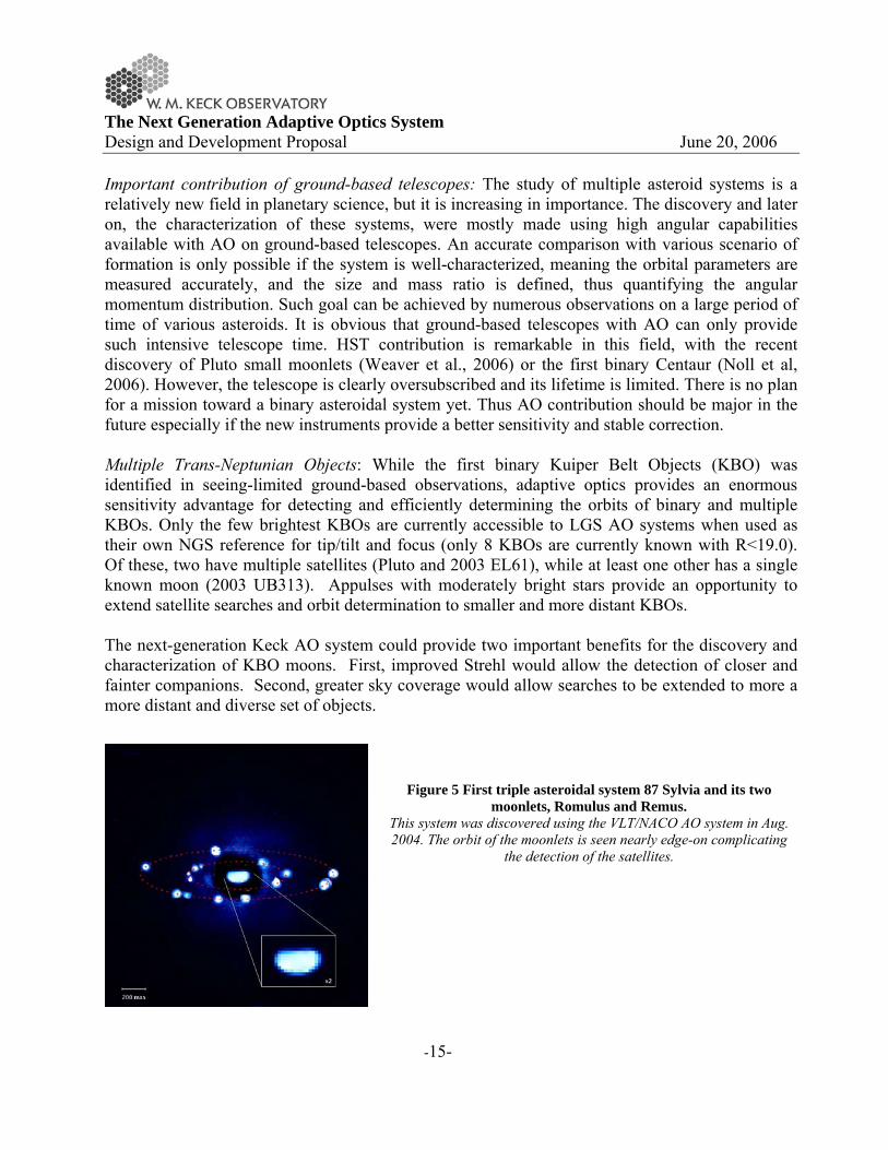
Figure 5 First triple asteroidal system 87 Sylvia and its two moonlets, Romulus and Remus.
This system was discovered using the VLT/NACO AO system in Aug. 2004. The orbit of the moonlets is seen nearly edge-on complicating
the detection of the satellites.

The Next Generation Adaptive Optics System Design and Development Proposal June 20, 2006
-16-
Table 2 Number of asteroids observable using the NGAO system. Per asteroid populations and considering various limit of magnitude for the tip-tilt reference (assuming on-axis
observations). Populations by brightness (numbered and unnumbered asteroids) Orbital type Total number V < 15 15 < V < 16 16 < V < 17 17 < V < 18 Near Earth 3923 1666 583 622 521 Main Belt 318474 4149 9859 30246 88049 Trojan 1997 13 44 108 273 Centaur 80 1 1 2 2 TNO 1010 1 2 0 2 Other 3244 140 289 638 870
3.2.2.2 Proposed observations and targets
Study of main-belt multiple systems: One of the main limitations of current AO observations for a large search of binary asteroid and characterization of their orbit is the limited quantity amount of asteroids observable considering the magnitude limit on the wavefront sensor. The Keck NGS AO system reaches a 13.5 magnitude, so ~1000 main-belt asteroids (to perihelion >2.15 AU and aphelion <3.3 AU) can be observed. The populations of asteroids located further away (Trojan and TNOs) are not accessible. Table 2 shows the total number of asteroids observable per population considering various limits for the wavefront sensor (see Appendix. Number of Observable Asteroids). We only considering here an on-axis reference study, using the asteroid itself as a reference. With NGAO, providing an excellent correction up to magnitude 17, 10% of the known main-belt population can be scanned, corresponding to the potential discovery of 1000-4000 multiple systems! Additionally because the NGAO system will provide a better and more stable correction (compared to the Keck LGS AO), the halo due to uncorrected phase will be significantly reduced. Closer and fainter satellites should be detectable; therefore we will be able to detect more multiple asteroid systems. More close binary systems could be also characterized because of the better angular resolution provided in the visible wavelength range (FWHM ~14 mas in R band). At the time of writing, the orbits of ~12 visual binary systems are known and displayed a diversity. To better understand these differences, we propose to focus our study on 100 new binary systems in the main-belt discovered by light curve or snap shot program on HST and/or previous AO systems. The increase by an order of magnitude of known orbits will help to how they formed considering, for instance, the asteroids is member of collisional family, their distance to the Sun, their size and shape, among others parameters. To reach a peak SNR~1000-3000 on an AO image, the typical total integration times for a 13, or 17 magnitude targets are 5min and 15 min respectively. Considering a typical overhead of 25 min (Marchis et al. 2004b) to move the telescope on the target and close the AO loop, the total telescope time per observation is ~30 min. The orbit of an asteroid can be approximated (P, a, e, i) after 8 consecutive observations (taken over a period of 1-2 months to limit the parallax effect),
The Next Generation Adaptive Optics System Design and Development Proposal June 20, 2006
-17-
corresponding to the need of 0.3 nights per object. Thirty nights of observation will be requested for this program over 3 years. To illustrate the gain in quality expected with NGAO, we generate a set of simulated images of the triple system 87 Sylvia. The binary nature of this asteroid was discovered in 2001 using the Keck NGS AO system. Marchis et al. (2005c) announced recently the discovery of a smaller and closer moonlet. The system is composed of D=280 km ellipsoidal primary around which two moons describe a circular and coplanar orbit: “Romulus”, the outermost moonlet (D=18 km) at 1356 km (~0.7”) and “Remus” (D = 7 km) at 706 km. (~0.35”). We added artificially two additional moonlets around the primary: “S1/New” (D=3.5 km) located between Romulus and Remus (at 1050 km) and “S2/New” (D=12 km) closer to the primary (at 480 km). This system is particularly difficult to observe since the orbits of the moon is nearly edge-on (see Figure 2). We blurred the image using the simulated NGAO and Keck NGS AO PSFs (with an rms error of 140 nm) and added Poisson and detector noises to reach a S/N of 2000 (corresponding to 1-3 min integration time for a 12th visible magnitude target). We then estimated if the moonlets could be detected and their intensity was measured by aperture photometry. Figure 4 displays a comparison for one observation between the Keck NGS AO, NGAO in two wavelengths, and HST/ACS. The angular resolution and thus the sensitivity of the NGAO R-band is a clear improvement and permits detection of the faintest moon of the system. Table 3 summarizes the detection rate for the pseudo-Sylvia system moonlets and the Δm (related to the size of the moonlet). The photometry was made using the same technique that for real observations (aperture photometry + fitting/correction of flux lost). The detection rates for NGAO-R band are 100% for all moons. One can also notice a very good photometric recovery with this AO system. The chance to discover multiple systems and to analyse them are significantly improved with the NGAO. It should be also emphasized that because the astrometric accuracy is also better (factor of 5 compared with NIRC-2 data), the determination of the orbital elements of the moons will be also more accurate (e.g., a significant eccentricity or small tilt of the orbit). Study of multiple TNOs: To demonstrate the likely improvement in detection sensitivity provided by an NGAO system, we have analyzed simulated images of a large multiple KBO, at various heliocentric distances. The primary and the brighter two satellites are given the sizes and orbital elements of those of 2003EL61, while a fainter inner satellite not excluded by the current observations of 2003EL61 is included as well. This four-object system was then placed at heliocentric distances from 50 to 100 AU, and imaged with a 30-minute K’ band integration using a camera with sensitivity and noise properties similar to NIRC2. We compared the probability of detecting KBO satellites between the current LGS AO system, the KNGAO in narrow field of view and in MCAO mode. Preliminary simulations indicate that the fraction of satellites detected using a 105 nm wavefront error NGAO is 2-4 times as high as using the current Keck AO + LGS. Surprisingly an MCAO could also increase the fraction of TNO satellites detected by improving the tip-tilt control in stellar appulse events.

The Next Generation Adaptive Optics System Design and Development Proposal June 20, 2006
-18-
Figure 6 Pseudo-87 Sylvia simulated. This display show the orbits and positions generated using the IMCCE physical ephemeris. Romulus orbits at ~1000
km from the Sylvia primary with a maximum angular separation of ~0.7”. Two new moonlets (called S/New1 and S/New2) were added artificially to the system.
Figure 7 Simulation of pseudo- Sylvia observed with various AO systems. [A] NGAO R [B] NGAO H-band, [D] NIRC-2 H-band. A comparison with [C] HST/ACS in R-band is also provided. A 0.1” scale is added on each image. The faintest moon (S/New1) is detectable with a good SNR only with NGAO R-band [A]. Romulus, the brightest moon, cannot be seen in the small central area displays for NGAO R-band image,
but this moon is obviously detected with this system.

The Next Generation Adaptive Optics System Design and Development Proposal June 20, 2006
-19-
Table 3 Detection rate and photometry on the moons of pseudo-Sylvia. (with various AO systems and wavelength of observations).
Romulus Remus S_New1 S_New2
Det. rate Δm Det. Rate Δm Det. Rate Δm Det. Rate Δm
Perfect image 100% 6.6 100% 8.1 100% 6.9 100% 9.6
NIRC2-H 82% 6.4±0.04 70% 8.3±0.3 11% 6.9±0.2 0% N/A
NGAO-H 100% 7.0±0.1 70% 8.5±0.5 40% 7.1±0.2 0% N/A
NGAO-R 100% 6.60±0.01 100% 8.3±0.1 100% 6.9±1.1 100% 10.1±0.3
3.2.2.3 AO and instrument requirements
An AO system providing full correction below <0.7 μm does not appear essential since the detectivity in this wave will be limited. This observing program requests essentially imaging capabilities and therefore remains relatively simple in its instrument requirements. An on-axis AO system will also to characterize a large number of known main-belt binary systems. An MCAO could be also optimum for the specific case of TNO moonlet detection and characterization. A visible imager is our first priority since more multiple asteroidal systems could be studied thanks to a better angular resolution providing also a more precise astrometric and photometric accuracy. A NIR camera imager should be also considered for the specific case of multiple TNOs. 3.2.2.4 References
Agnor, C.B. and Hamilton, D.P., Neptune's capture of its moon Triton in a binary-planet gravitational encounter, Nature 441, 7090, 192-194.
Belton, M., Chapman, C., Thomas, P. et al., 2005. The bulk density of asteroid 243 Ida from Dactyl’s orbit, Nature 374, 785-788.
Cuk, M. and Burns, J.A., 2005. Effects of thermal radiation on the dynamics of binary NEAs, Icarus 176, 2, 418-431.
Descamps, P., Marchis, F., Michalowski, et al., 2005. Insights on 90 Antiope double asteroid combining VLT-AO and Lightcurve Observations, ACM-IAU meeting, Buzios, Rio de Janeiro, Brazil

The Next Generation Adaptive Optics System Design and Development Proposal June 20, 2006
-20-
Durda, D.D., Bottke, W.F., Enke, B.L. et al., 2004. The formation of asteroid satellites in large impacts: results from numerical simulations, Icarus 170, 1, 243-257.
Marchis , F., Descamps, P., Hestroffer, D. et al., 2003. A three-dimensional solution for the orbit of the asteroidal satellite of 22 Kalliope, Icarus 165, 1, 112-120.
Marchis, F., J. Berthier, P. Descamps, et al. 2004b. Studying binary asteroids with NGS and LGS AO systems, SPIE Proceeding, Glasgow, Scotland, 5490, 338-350.
Marchis Descamps, P., Hestroffer, D. et al., 2004a. Fine Analysis of 121 Hermione, 45 Eugenia, and 90 Antiope Binary Asteroid Systems with AO Observations, AAS-DPS #36, #46.02
Marchis , F., Descamps, P., Hestroffer, D. et al., 2005a. On the Diversity of Binary Asteroid Orbits, ACM-IAU meeting, Buzios, Rio de Janeiro, Brazil.
Marchis , F., Hestroffer, D., Descamps, P. et al., 2005b. Mass and density of Asteroid 121 Hermione from an analysis of its companion orbit, Icarus 178, 2, 450-464.
Marchis, F., Descamps, P., Hestroffer, D. et al., 2005c. Discovery of the triple asteroidal system 87 Sylvia, Nature 436, 7052, 822-824.
Merline, W.J., Close, L.M., Dumas, C. et al. 1999. Discovery of a moon orbiting the asteroid 45 Eugenia, Nature 401, 565-567.
Noll, K.S., Levison, H.F., Grundy, W.M. et al. 2006. Discovery of a Binary Centaur, submitted to Icarus.
Weaver, H.A., Stern, S.A., Mutchler, M.J., et al. 2006. Discovery of two new satellites of Pluto, Nature 439, 7079, 943-945.
3.2.3 Size and Shape of Asteroids
Contributor: Joshua Emery (NASA-Ames), F. Marchis (UC-Berkeley)
3.2.3.1 Scientific Background
Asteroids constitute the debris left over from the formation of the Solar System. Because of their small to moderate sizes (as compared to the planets), they have generally not undergone any late-stage endogenic alteration. Their surfaces therefore still sport the scars of early and late-stage collisional evolution and early-stage geologic processes, along with other ongoing exogenic surface processes (i.e. space weathering). Adaptive optics observations of asteroids can play a key role in revealing what this debris has to show us about the formation and evolution of the Solar System. This section first discusses three specific areas of asteroid research that can be addressed by disk-resolved observations. This short list is not meant to be exhaustive; many additional applications of improved AO to asteroid science could be included and will undoubtedly be pursued as more
The Next Generation Adaptive Optics System Design and Development Proposal June 20, 2006
-21-
scientists consider the possibilities. The section ends with an overview of the improvement offered by NGAO in terms of increased number of asteroids that will be resolved. 3.2.3.1.1 Collisional Evolution of the Asteroid Belt
Imaging of asteroids with improved spatial resolution can significantly impact the understanding of the accretional and collisional evolution of the Solar System. The presently observed properties of the Main Belt depend on many factors, including the initial conditions (e.g., total initial mass in Main Belt, compositional distribution of this mass, timing of Jupiter’s formation) and evolution processes (e.g., collisional and fragmentation laws, migration of giant planets, degree of mixing). These are complex processes that are being modeled with ever increasing sophistication, but require observational constraints. Fortunately, the asteroids themselves, when properly observed, provide the many clues that are necessary to unravel the different factors. As stated by Bottke et al. (2005b), “Like archaeologists working to translate stone carvings left behind by ancient civilizations, the collisional and dynamical clues left behind in or derived from the Main Belt, once properly interpreted, can be used to read the history of the inner Solar System.” One strong constraint would be the asteroid cratering record, particularly the occurrence of large craters on large asteroids. For example, imaging by HST with a spatial resolution of ~36 km/pixel has revealed a large impact basin (~460 km diameter) at the south pole of the basaltic (differentiated) asteroid 4 Vesta, which itself has a diameter of ~560 km (Thomas et al. 1997). The existence of this single large impact basing on Vesta has already been used as a primary constraint in multiple collisional evolution models (e.g., Bottke et al. 2005a, O’Brien and Greenberg 2005). The argument used is that large collisions should be frequent enough that the impact on Vesta is not too unlikely, but not so frequent that many large impacts should have occurred. While this is insightful use of recent observational data, one must always be wary of statistics drawn from a sample size of one. Vesta’s surface could potentially be a statistical outlier, in which case extending its properties to the entire asteroid belt would be an astronomical red herring. Spatially resolved imaging of other large asteroids is critical in order to place the results for Vesta into context and to derive truly reliable statistical constraints on large collisions throughout the Main Belt. Observations of the 15 or 20 largest asteroids would provide the statistics necessary to put much stronger constraints on the frequency of these large collisions. We estimate that 20 Main Belt asteroids will be resolved with sufficient resolution with NGAO in R-band (33 in V-band) for mapping comparable to that done previously for 4 Vesta. This compares with only one (Ceres) that is available from the current Keck AO (K-band). The criterion for these results is that the fractional resolution (spatial resolution divided by diameter) be equal to or smaller than for the HST observations of Vesta (36km/560km = 0.065). The NGAO resolution in R-band on Vesta is ~11 km, an improvement of more than a factor of three over the HST data. The largest part of the improvement is the extension of high Strehl diffraction limited performance to shorter wavelengths. Comparing imaging results for large asteroids of different taxonomic types (and
The Next Generation Adaptive Optics System Design and Development Proposal June 20, 2006
-22-
therefore presumably different compositions) will also reveal information about how surface structure and strength varies among asteroids (e.g. O’Brien et al. 2006). 3.2.3.1.2 Size Distribution
The size distribution of the Main Belt as a whole and of various sub-populations is a major property that must be properly explained by any model. The initial size distribution of the Main Belt was set by the accretion process – the number of objects of a given size that grew during that stage. Collisional and dynamical erosion since then have left their marks as well, altering the initial distribution. The size distributions of other populations likewise depend on their formation and evolutionary environment. The distributions within asteroid families are initially set by fragmentation laws, which are themselves uncertain and vary for different compositions. The size distribution of near-Earth objects is set by the delivery mechanism from the Main Belt, which is very likely size dependent. Without accurate knowledge of the sizes of asteroids, it is impossible to decode the information contained in the size distributions. Visible, disk-integrated photometry is not able to determine the size of an object, only the brightness – the size and albedo cannot be unraveled without additional information. Direct imaging is the most straightforward means of size determination. Other methods, such as radiometry – in which the thermal emission is measured at the same time as visible reflected flux – depend on a large number of parameters that are generally poorly known. The radiometric method in particular was used to derive the sizes of a large number of Main Belt asteroids, but it first had to be calibrated because of uncertainties in several effects, including thermal inertia, thermal-IR phase functions, and “beaming” (due to surface roughness) (Lebofsky et al. 1989). The calibration used for large, Main Belt asteroids has been shown to be inappropriate for smaller objects, and especially for near-Earth objects, which are often observed at high phase angles (Walker 2003, Delbo et al. 2003, Wolters et al. 2005). The most straightforward approach would be a large, direct imaging campaign of thousands of asteroids. This is probably not feasible on the Keck telescopes because of the time involved, but NGAO will provide the capability to directly measure sizes for a significant sub-sample that spans the range of sizes, compositions, shapes, orbital classes, dynamical families, and viewing geometries. These observations can then anchor the distributions of each subgroup, recalibrating the results of other methods to make them more reliable. With NGAO in R-band, there would be 1193 observable objects to choose from (Table 2). We estimate that ~300 directly imaged asteroids, if well chosen, would be adequate to provide such an anchor. Marchis et al. (2006) initiated such survey with the Keck NGS AO and observed 30 asteroids over a few half-nights. Considering an overhead of ~20 min per object and an integrations time of 5-15 min per object, such ambitious program could be completed in 12 nights. Well-calibrated size distributions of asteroid families will in turn allow the investigation of the physics of disruption and fragmentation, which is a key uncertainty in evolutionary models. The
The Next Generation Adaptive Optics System Design and Development Proposal June 20, 2006
-23-
same is true for a properly anchored size distribution of near-Earth objects. In fact, there are currently very few NEOs with known sizes. This also presents a problem for hazard mitigation (i.e., detecting and stopping potentially devastating impactors) since the number of objects in near-Earth space that could cause regional catastrophes is currently unknown. 3.2.3.1.3 Geologic Properties and Surface Heterogeneity
The largest asteroids have been, and possible still could be, geologically active bodies in their own right. It appears that some large asteroids differentiated – Vesta has a basaltic crust and the M-type asteroids are thought to be remnant cores of disrupted, differentiated asteroids – but many others did not. These differences are still unexplained. Some hypotheses pose that volatile content was an important inhibitor of differentiation, others point to the change in silicate mineralogy with heliocentric distance, and still others suggest that the heat source (e.g., radioisotopes or induction heating) was somehow not uniformly distributed among asteroids. Direct observation of large asteroids, both differentiated and not, is the best approach to understand this current conundrum. Imaging can directly discover surface heterogeneities in the form of albedo variations across the surface. These can be strong clues to different geologic units (e.g., lava flows on Vesta, carbonate/organic/water/clay deposits on Ceres). Detailed shape analysis can also provide information the internal composition and structure. As an example, the very nearly spherical shape of Ceres as determined by HST imaging has been used to infer that it is actually a differentiated icy object, with an H2O mantle surrounding a rocky core (Thomas et al. 2005). The non-homogeneous shape of Vesta, on the other hand, reflects the different rheologies (Thomas et al. 1997, 2005). Accretion and later collisional evolution were not uniform across the inner Solar System, as generally modeled, but were affected by the different materials present at different distances from the Sun. NGAO imaging will allow an investigation of the results of these differences through shape as well as albedo mapping. Disk-resolved spectroscopy is another powerful means of mapping geology. The extension of NGAO to shorter wavelengths will allow complete characterization of the important 1-μm silicate band, permitting the mapping of detailed silicate mineralogy on individual surfaces. A water of hydration band at ~0.7 μm can also be mapped to help understand the effects of water on individual asteroids (i.e., were isolated areas altered, perhaps by impacts, or entire asteroids or groups of asteroids by amore wide-spread event?). Additionally, there is recent spectral evidence for silicates on the surface of some M-type (presumably metallic) asteroids. Are these asteroids not metallic, or are they metallic with a silicate covering, perhaps remnant mantle material? Such a remnant mantle might provide only partial coverage, and could therefore be mapped by NGAO disk-resolved spectroscopy.

The Next Generation Adaptive Optics System Design and Development Proposal June 20, 2006
-24-
3.2.3.1.4 Improvements in Number of Resolvable Asteroids by NGAO
Table 4 summarizes the number of asteroids resolvable from visible to near-IR domain and per population (see Appendix. Number of Observable Asteroids for more details). Thanks to the high angular resolution provided in V and R bands, ~800 main-belt asteroids could be resolved and have their shape estimate with a precision of less than 7%. With current AO system ~100 asteroids, located only in the main-belt, can be resolved. The determination of the size and shape of Trojan asteroids, even if limited to a few of them, will be useful to estimate their albedo. For NEAs, the large number of resolvable objects is a result of very close approaches to Earth. Many of these are unnumbered, and so refined orbits may bring them not nearly as close.
Table 4 Number of asteroids resolvable with Keck NGAO in various wavelength ranges and per population. Unnumbered asteroids (most of the NEAs) have poorly known orbits. Resolvable asteroids in each band (numbered and unnumbered) Orbital type V R I J H K Near Earth 526 460 376 269 204 152 Main Belt 855 716 526 319 194 100 Trojan 13 11 5 0 0 0 Centaur 1 1 1 0 0 0 TNO 3 3 3 3 3 3 Other 4 2 1 0 0 0
3.2.3.2 References
Bottke, W.F., D.D. Durda, D. Nesvorny et al. 2005a. The fossilized size distribution of the main asteroid belt. Icarus 175, 111-140.
Bottke, W.F., D.D. Durda, D. Nesvorny et al. 2005b. Linking the collisional history of the main
asteroid belt to its dynamical excitation and depletion. Icarus 179, 63-94. Delbo, M., Harris, A.W., Binzel, R.P., Pravec, P., Davies, J.K. 2003. Keck observations of near-
Earth asteroids in the thermal infrared. Icarus 166, 116-130. Lebofsky, L.A. and Spencer, J.R. 1989. Radiometry and thermal modeling of asteroids. In
Asteroids II (R.P. Binzel, T. Gehrels, and M.S. Matthews, Eds.), pp. 128-147, Univ. Ariz. Press, Tucson.
Marchis, F. Kaasalainen, M., Hom, E.F.Y., et al. 2006. Size, Shape, and multiplicity of main-belt asteroids. I. Keck Adaptive Optics Survey, submitted to Icarus. O’Brien, D.P., and R. Greenberg 2005. The collisional and dynamical evolution of the main belt
and NEA size distributions. Icarus 178, 434-449.
The Next Generation Adaptive Optics System Design and Development Proposal June 20, 2006
-25-
O’Brien, D.P., R. Greenberg, J.E. Richardson 2006. Craters on asteroids: Reconciling diverse
impact records with a common impacting population. Icarus in press (available online). Thomas, P.C., R. P. Binzel, M.J. Gaffey, et al. 1997. Impact excavation on asteroid 4 Vesta:
Hubble Space Telescope results. Science 277, 1492-1495. Thomas, P.C., J.Wm. Parker, L.A. McFadden, et al. 2005. Differentiation of the asteroid Ceres as
revealed by its shape. Nature 437, 224-226. Walker, R.G. 2003. IRAS diameters and albedos revisited. DPS 35, abstract #34.19. Wolters, S.D., Green, S.F., McBride, N., Davies, J.K. 2005. Optical and thermal infrared
observations of six near-Earth asteroids in 2002. Icarus 175, 92-110. 3.2.4 Moonlet Spectroscopy
Contributor: Franck Marchis (UC-Berkeley), Joshua Emery (NASA-Ames)
3.2.4.1 Scientific Background: Satellites around minor planets
In section 3.2.2.1, we discuss the existence of multiple asteroidal systems, the detection of the moons in these systems, and the study of their orbits with AO. At the time of writing ~85 binary asteroid systems are known or suspected. One of the key goals in the subfield of multiple asteroid studies is to reveal the nature of these asteroid systems. Several scenarios for the formation of multiple asteroid systems have been envisioned: capture of a fragment after an oblique impact, tidal splitting by close encounter, fission, disruption and reaccretion of large fragments followed by a capture of small ones, and capture after close encounter, among others. Reflectance spectroscopy of the primary and its moonlet in the visible and near-infrared (~0.65 to 2.5 μm) will help constrain the origin of each system. Broadly differing spectra (i.e., differing number, depth, width, and positions of absorption features) are indicative of differing surface mineralogies. Different surface mineralogy between a moonlet and asteroid primary would be expected for several of the formation scenarios listed above. If the multiple system formed from disruption and reaccretion of large fragments, the interior composition of both the impactor and target would be exposed and mixed with the exterior material. This would lead to heterogeneous composition of fragments, with mineralogical signatures indicative of core, mantle, and crustal materials for differentiated objects, and unweathered primordial material for undifferentiated objects. Visible and NIR spectra can be used to identify these various compositions. Tidal splitting and fission, however, are expected to produce components that are identical in composition. Identification of systems with very similar spectral characteristics would support one of these two formation
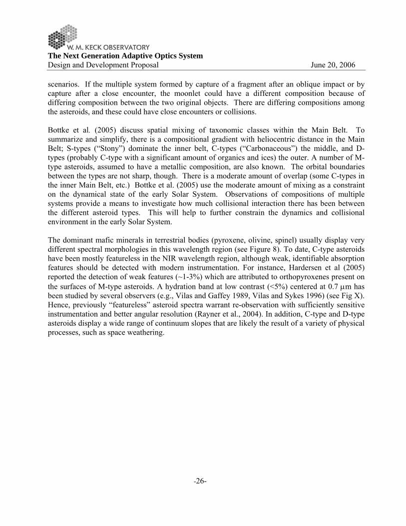
The Next Generation Adaptive Optics System Design and Development Proposal June 20, 2006
-26-
scenarios. If the multiple system formed by capture of a fragment after an oblique impact or by capture after a close encounter, the moonlet could have a different composition because of differing composition between the two original objects. There are differing compositions among the asteroids, and these could have close encounters or collisions. Bottke et al. (2005) discuss spatial mixing of taxonomic classes within the Main Belt. To summarize and simplify, there is a compositional gradient with heliocentric distance in the Main Belt; S-types (“Stony”) dominate the inner belt, C-types (“Carbonaceous”) the middle, and D-types (probably C-type with a significant amount of organics and ices) the outer. A number of M-type asteroids, assumed to have a metallic composition, are also known. The orbital boundaries between the types are not sharp, though. There is a moderate amount of overlap (some C-types in the inner Main Belt, etc.) Bottke et al. (2005) use the moderate amount of mixing as a constraint on the dynamical state of the early Solar System. Observations of compositions of multiple systems provide a means to investigate how much collisional interaction there has been between the different asteroid types. This will help to further constrain the dynamics and collisional environment in the early Solar System. The dominant mafic minerals in terrestrial bodies (pyroxene, olivine, spinel) usually display very different spectral morphologies in this wavelength region (see Figure 8). To date, C-type asteroids have been mostly featureless in the NIR wavelength region, although weak, identifiable absorption features should be detected with modern instrumentation. For instance, Hardersen et al (2005) reported the detection of weak features (~1-3%) which are attributed to orthopyroxenes present on the surfaces of M-type asteroids. A hydration band at low contrast (<5%) centered at 0.7 μm has been studied by several observers (e.g., Vilas and Gaffey 1989, Vilas and Sykes 1996) (see Fig X). Hence, previously “featureless” asteroid spectra warrant re-observation with sufficiently sensitive instrumentation and better angular resolution (Rayner et al., 2004). In addition, C-type and D-type asteroids display a wide range of continuum slopes that are likely the result of a variety of physical processes, such as space weathering.
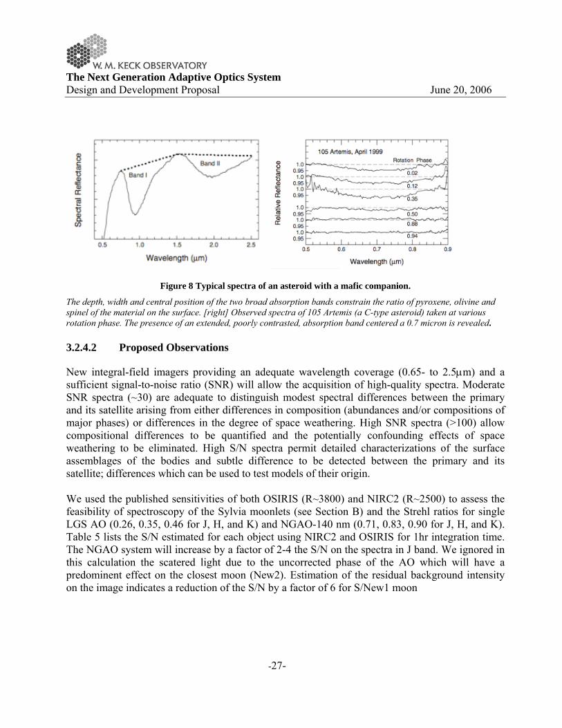
The Next Generation Adaptive Optics System Design and Development Proposal June 20, 2006
-27-
Figure 8 Typical spectra of an asteroid with a mafic companion.
The depth, width and central position of the two broad absorption bands constrain the ratio of pyroxene, olivine and spinel of the material on the surface. [right] Observed spectra of 105 Artemis (a C-type asteroid) taken at various rotation phase. The presence of an extended, poorly contrasted, absorption band centered a 0.7 micron is revealed. 3.2.4.2 Proposed Observations
New integral-field imagers providing an adequate wavelength coverage (0.65- to 2.5μm) and a sufficient signal-to-noise ratio (SNR) will allow the acquisition of high-quality spectra. Moderate SNR spectra (~30) are adequate to distinguish modest spectral differences between the primary and its satellite arising from either differences in composition (abundances and/or compositions of major phases) or differences in the degree of space weathering. High SNR spectra (>100) allow compositional differences to be quantified and the potentially confounding effects of space weathering to be eliminated. High S/N spectra permit detailed characterizations of the surface assemblages of the bodies and subtle difference to be detected between the primary and its satellite; differences which can be used to test models of their origin. We used the published sensitivities of both OSIRIS (R~3800) and NIRC2 (R~2500) to assess the feasibility of spectroscopy of the Sylvia moonlets (see Section B) and the Strehl ratios for single LGS AO (0.26, 0.35, 0.46 for J, H, and K) and NGAO-140 nm (0.71, 0.83, 0.90 for J, H, and K). Table 5 lists the S/N estimated for each object using NIRC2 and OSIRIS for 1hr integration time. The NGAO system will increase by a factor of 2-4 the S/N on the spectra in J band. We ignored in this calculation the scatered light due to the uncorrected phase of the AO which will have a predominent effect on the closest moon (New2). Estimation of the residual background intensity on the image indicates a reduction of the S/N by a factor of 6 for S/New1 moon
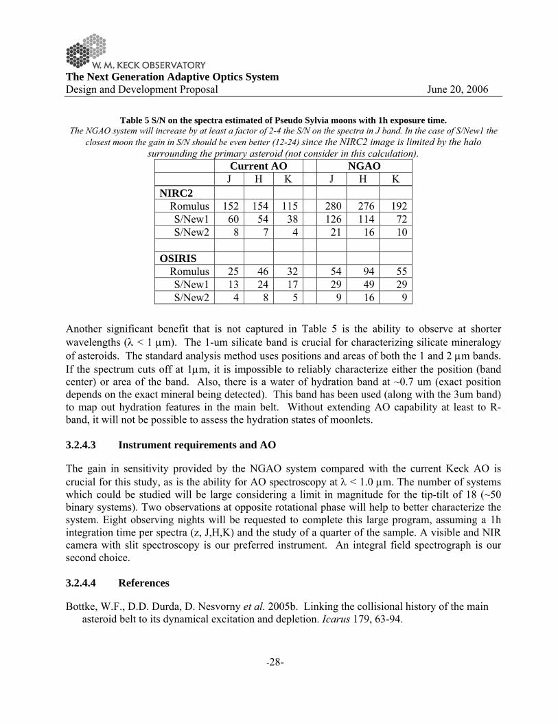
The Next Generation Adaptive Optics System Design and Development Proposal June 20, 2006
-28-
Table 5 S/N on the spectra estimated of Pseudo Sylvia moons with 1h exposure time. The NGAO system will increase by at least a factor of 2-4 the S/N on the spectra in J band. In the case of S/New1 the
closest moon the gain in S/N should be even better (12-24) since the NIRC2 image is limited by the halo surrounding the primary asteroid (not consider in this calculation).
Current AO NGAO J H K J H K NIRC2 Romulus 152 154 115 280 276 192 S/New1 60 54 38 126 114 72 S/New2 8 7 4 21 16 10
OSIRIS Romulus 25 46 32 54 94 55 S/New1 13 24 17 29 49 29 S/New2 4 8 5 9 16 9
Another significant benefit that is not captured in Table 5 is the ability to observe at shorter wavelengths (λ < 1 μm). The 1-um silicate band is crucial for characterizing silicate mineralogy of asteroids. The standard analysis method uses positions and areas of both the 1 and 2 μm bands. If the spectrum cuts off at 1μm, it is impossible to reliably characterize either the position (band center) or area of the band. Also, there is a water of hydration band at ~0.7 um (exact position depends on the exact mineral being detected). This band has been used (along with the 3um band) to map out hydration features in the main belt. Without extending AO capability at least to R-band, it will not be possible to assess the hydration states of moonlets. 3.2.4.3 Instrument requirements and AO
The gain in sensitivity provided by the NGAO system compared with the current Keck AO is crucial for this study, as is the ability for AO spectroscopy at λ < 1.0 μm. The number of systems which could be studied will be large considering a limit in magnitude for the tip-tilt of 18 (~50 binary systems). Two observations at opposite rotational phase will help to better characterize the system. Eight observing nights will be requested to complete this large program, assuming a 1h integration time per spectra (z, J,H,K) and the study of a quarter of the sample. A visible and NIR camera with slit spectroscopy is our preferred instrument. An integral field spectrograph is our second choice. 3.2.4.4 References
Bottke, W.F., D.D. Durda, D. Nesvorny et al. 2005b. Linking the collisional history of the main asteroid belt to its dynamical excitation and depletion. Icarus 179, 63-94.
The Next Generation Adaptive Optics System Design and Development Proposal June 20, 2006
-29-
Hardersen, P.S., M.J. Gaffey, P.A. Abell 2005. Near-IR spectral evidence for the presence of iron-poor orthopyroxenes on the surfaces of six M-type asteroids. Icarus 175, 141-158.
Rayner, J.T., P.M. Onaka, M.C. Cushing, W.D. Vacca 2004. Four years of good SpeX. In Ground-based Instrumentation for Astronomy: Proceedings of the SPIE. (A. Moorwood and I. Masanori, Eds.), 5492, 1498-1509.
Vilas, F. and M.J. Gaffey 1989. Phyllosilicate absorption features in Main-Belt and Outer-Belt asteroid reflectance spectra. Science 246, 790-792.
Vilas, F. and M.V. Sykes 1996. Are low-albedo asteroids thermally metamorphosed? Icarus 124, 483-489.
3.2.5 Titan – The coupled surface-atmosphere system with NGAO
Contributors; Máté Ádámkovics (UC Berkeley), Franck Marchis (UC Berkeley), Antonin Bouchez (Caltech)
3.2.5.1 Scientific Background
After the discovery of methane (and thereby a dense atmosphere) on Titan, the largest moon of Saturn has stood out in contrast to all other satellites. How such a small body developed and maintains its atmosphere, while other satellites do not, remains a mystery of planetary science and solar system formation. Part of the puzzle is understanding the path Titan has taken to arrive at it's current state with 1.5 bar of nitrogen, trace amounts (~5%) of methane, complex haze structures, and a variety of cloud types. Methane is short-lived in the atmosphere due to photolysis and must be constantly replenished. Surface reservoirs of liquid hydrocarbons were once believed to be the source of methane, but they don't currently exist. Nonetheless, there could have been hydrocarbon oceans on Titan at some point in the past, and the surface was measured by the Huygens probe to be `moist'. So it is unclear if the source of methane comes from the deep within the interior (Tobie et al, 2006) or from near the surface. Methane on Titan plays the role that water does on Earth because they are both close to their respective triple points, and the surface on Titan is coupled to the atmosphere via a methane-based meteorological cycle (Takano et al., 2001). Temporal variations in one part of the surface-atmosphere system will result in concomitant changes throughout the planet, yet this has only been inferred and has not been observed directly. Measuring seasonal differences on Titan, such as changes in cloud properties (Griffith et al., 2005) and the surface albedo with time, will aid in determining how Titan has evolved to its current state. Titan’s year is roughly 30 Earth years, so observing the response of the planet to seasonal changes involves using a few Voyager era observations with an increasing number of ground-based and spacecraft measurements. However, improving the sensitivity and resolution of ground-based observations leads directly to a greater number of dynamical variations that can be measured on shorter timescales (Brown et al., 2002). This is because small-scale changes such observables as clouds formation and haze density occur more frequently and rapidly than large-scale changes. As an example, the Cassini spacecraft and Huygens probe have provided a number of exceptionally

The Next Generation Adaptive Optics System Design and Development Proposal June 20, 2006
-30-
high spatial resolution measurements showing the small-scale (<100km) dynamical changes in haze density due to circulation. A limitation of the spacecraft measurements is the frequency, duration, and coverage of the observations. This limitation is well completemented by ground-based efforts. Indeed, Cassini will have raised more questions than it answers after the nominal completion of the mission in 2008, and ground-based measurements (particularly at high spatial and spectral resolution in the infrared) will be necessary to evaluate and confirm speculation about the long-term changes on Titan. 3.2.5.2 Proposed observations and targets
There are two strategies for observing Titan in the near-infrared at Keck. The traditional method devotes a half night to observations – roughly 2 to 4 times a semester -- with an instrument such as NIRSPEC, NIRC2 or OSIRIS. This method gives a detailed snapshot of the planet, usually over multiple wavelength bands, since images or spectra in single band can be obtained in a few minutes to hours. K-band band has been the waveband of choice for most analysis due to a number of considerations, including higher Strehl and lower haze opacity on Titan, but side-by-side comparisons of images in multiple bands can be indicative of surface diversity (see Figure 9). Characterizing the surface (for example) with imaging spectroscopy is necessary for quantitative retrievals of surface albedos, which can be used for diagnosing surface composition (Ádámkovics et al., 2006). A necessary requirement in retrieving the surface albedo is a characterization and treatment of flux due to clouds and haze in Titan’s atmosphere (Ádámkovics et al., 2004). Algorithms for scrutinizing the atmosphere are maturing, and upcoming research will focus on monitoring temporal variation in the surface at atmosphere, which requires another mode of more routine observations. It has been demonstrated at Keck that a “non-traditional” mode of monitoring Titan --- very regularly, and for short periods of time (minutes) --- can yield dramatic scientific results about Titan’s atmosphere via the statistics of cloud formation and properties such as location and lifetime (http://www2.keck.hawaii.edu/science/titan/index.html). Narrowband measurements of surface features are can be contaminated by low altitude haze and clouds, and the monitoring with OSIRIS (or super-OSIRIS), would yield discriminate between surface feature and low-altitude atmospheric phenomena. Spatial variation with the current AO system may be observable, however, higher spatial resolution systems would be more likely to observe surface variations in a shorter timeframe.

The Next Generation Adaptive Optics System Design and Development Proposal June 20, 2006
-31-
Figure 9 Simultaneous H- and K-band images of Titan from the ground (Ádámkovics et al., 2006). The 0.9µm Cassini/ISS map has been reprojected to give an indication of the expected near-IR surface albedo. Image slices taken from a spectral image datacube show that patterns of H-band and K-band surface albedo patterns do not
always correspond. The angular diameter of Titan is 0.8”.
3.2.5.3 Comparison of NGAO with current LGS AO
3.2.5.3.1 Simulations
In order to compare the benefits of an NGAO system over the current AO system, we developed a model of simulated observations based on a high spatial resolution surface map of Titan from Cassini/ISS (at 0.9µm) convolved with the expected instrument profile and performance of the planned NGAO system. The model is first tested against existing observations with NIRC2 and to confirm the accuracy of the simulation and then relevant AO performance characteristics from the proposed NGAO system are used to produce a simulated image of Titan with the new system (see Figure 10).
Figure 10 Validation of simulation with observations along with examples of expected NGAO performance. The Keck simulation is based on a 0.9 μm map generated through Cassini observations. Simulated image and
observations may be slightly different because variation the color of surface feature, for instance the bright southern pole is rather dark on our simulation. The angular diameter of Titan is 0.8”.
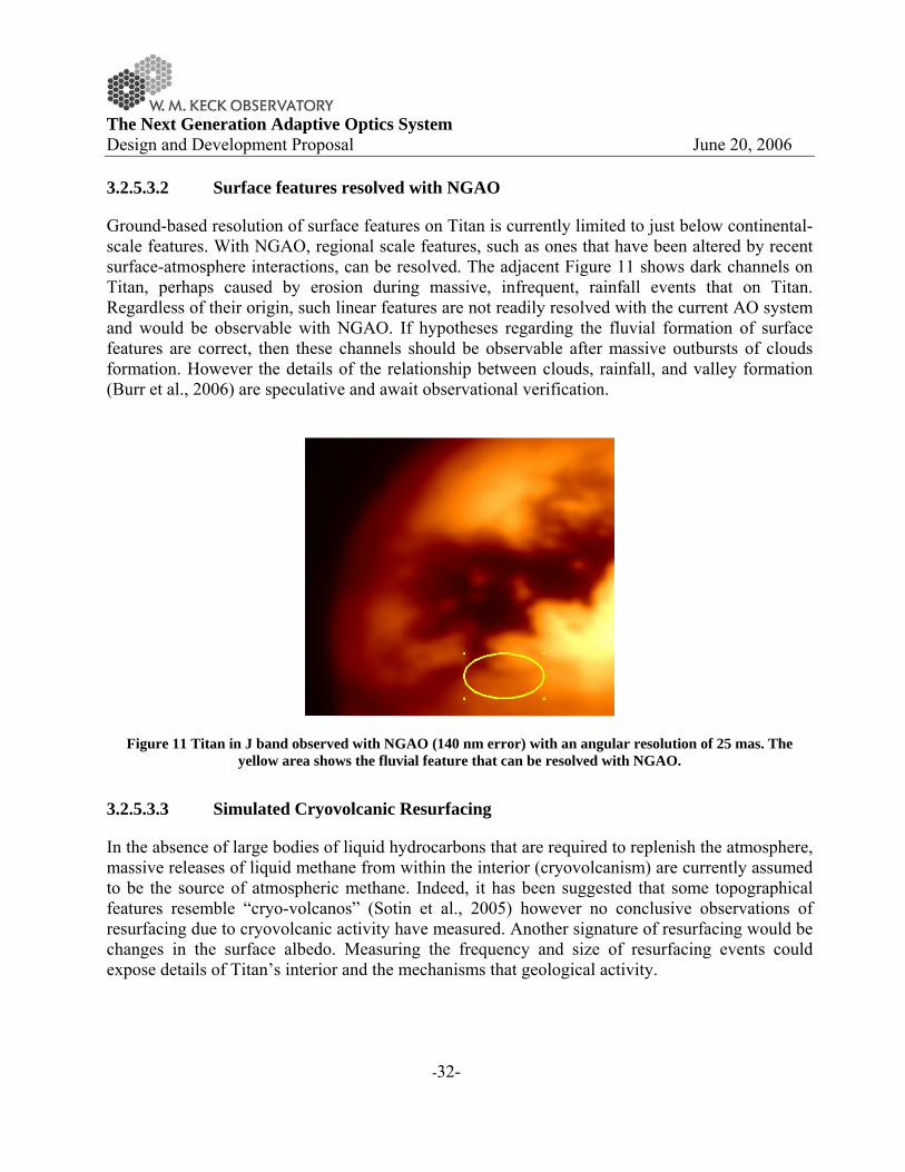
The Next Generation Adaptive Optics System Design and Development Proposal June 20, 2006
-32-
3.2.5.3.2 Surface features resolved with NGAO
Ground-based resolution of surface features on Titan is currently limited to just below continental-scale features. With NGAO, regional scale features, such as ones that have been altered by recent surface-atmosphere interactions, can be resolved. The adjacent Figure 11 shows dark channels on Titan, perhaps caused by erosion during massive, infrequent, rainfall events that on Titan. Regardless of their origin, such linear features are not readily resolved with the current AO system and would be observable with NGAO. If hypotheses regarding the fluvial formation of surface features are correct, then these channels should be observable after massive outbursts of clouds formation. However the details of the relationship between clouds, rainfall, and valley formation (Burr et al., 2006) are speculative and await observational verification.
Figure 11 Titan in J band observed with NGAO (140 nm error) with an angular resolution of 25 mas. The yellow area shows the fluvial feature that can be resolved with NGAO.
3.2.5.3.3 Simulated Cryovolcanic Resurfacing
In the absence of large bodies of liquid hydrocarbons that are required to replenish the atmosphere, massive releases of liquid methane from within the interior (cryovolcanism) are currently assumed to be the source of atmospheric methane. Indeed, it has been suggested that some topographical features resemble “cryo-volcanos” (Sotin et al., 2005) however no conclusive observations of resurfacing due to cryovolcanic activity have measured. Another signature of resurfacing would be changes in the surface albedo. Measuring the frequency and size of resurfacing events could expose details of Titan’s interior and the mechanisms that geological activity.
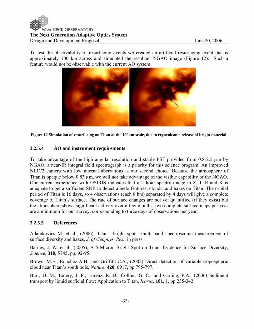
The Next Generation Adaptive Optics System Design and Development Proposal June 20, 2006
-33-
To test the observability of resurfacing events we created an artificial resurfacing event that is approximately 100 km across and simulated the resultant NGAO image (Figure 12). Such a feature would not be observable with the current AO system
Figure 12 Simulation of resurfacing on Titan at the 100km scale, due to cryovolcanic release of bright material.
3.2.5.4 AO and instrument requirements
To take advantage of the high angular resolution and stable PSF provided from 0.8-2.5 μm by NGAO, a near-IR integral field spectrograph is a priority for this science program. An improved NIRC2 camera with low internal aberrations is our second choice. Because the atmosphere of Titan is opaque below 0.83 μm, we will not take advantage of the visible capability of the NGAO. Our current experience with OSIRIS indicates that a 2 hour spectro-image in Z, J, H and K is adequate to get a sufficient SNR to detect albedo features, clouds, and hazes on Titan. The orbital period of Titan is 16 days, so 4 observations (each 8 hrs) separated by 4 days will give a complete coverage of Titan’s surface. The rate of surface changes are not yet quantified (if they exist) but the atmosphere shows significant activity over a few months; two complete surface maps per year are a minimum for our survey, corresponding to three days of observations per year. 3.2.5.5 References
Ádámkovics M. et al., (2006), Titan's bright spots: multi-band spectroscopic measurement of surface diversity and hazes, J. of Geophys. Res., in press.
Barnes, J. W. et al., (2005), A 5-Micron-Bright Spot on Titan: Evidence for Surface Diversity, Science, 310, 5745, pp. 92-95.
Brown, M.E., Bouchez A.H., and Griffith C.A., (2002) Direct detection of variable tropospheric cloud near Titan’s south pole, Nature, 420, 6917, pp.795-797.
Burr, D. M., Emery, J. P., Lorenz, R. D., Collins, G. C., and Carling, P.A., (2006) Sediment transport by liquid surficial flow: Application to Titan, Icarus, 181, 1, pp.235-242.

The Next Generation Adaptive Optics System Design and Development Proposal June 20, 2006
-34-
Griffith, C. A. et al., (2005), The Evolution of Titan's Mid-Latitude Clouds, Science, 310, 5747, pp. 474-477.
Sotin, C. et al., (2005), Release of volatiles from a possible cryovolcano from near-infrared imaging of Titan, Nature, 435, 7043, pp. 786-789.
Tobie, G., Lunine, J. I., and Sotin, C., (2006), Episodic outgassing as the origin of atmospheric methane on Titan, Nature, 440, 7080, pp. 61-64.
Tokano, T., Neubauer, F. M., Laube, M., McKay, C. P., (2001), Three-Dimensional Modeling of the Tropospheric Methane Cycle on Titan, Icarus, 153, 1, pp. 130-147.
3.2.6 Study of Io volcanic activity
Contributor: F. Marchis (UC-Berkeley)
3.2.6.1 Scientific background
Io is a key target for future exploration. It is a fascinating world in its own right and, as the most dynamic body in the Solar System, this satellite occupies a unique place in planetary science. It is the only place beyond Earth where we can watch active volcanism happen on a large scale. Io is the best target for the study of tidal heating, a process of fundamental importance to the evolution of planetary satellite systems, and one that may greatly expand the habitability zone for extra-terrestrial life. Io’s tidal heating is intimately connected to Europa’s, which is thought to maintain an ocean of liquid water underneath an icy crust. Although spacecraft have significantly advanced our knowledge of Io, several key questions remain unsolved. Recent data collected by Galileo spacecraft, along with important contributions from ground-based telescopes with AO and HST, have revolutionized our understanding of the nature of this most exotic moon. Until the arrival of a new mission to the Jovian system with dedicated Io observations, the exploration of Io and study of its volcanism lies largely in the hands of ground-based observers. One of the most striking effects of Io volcanism is the presence of hot spots on the surface that are detectable in the near-infrared. They correspond to the thermal emission of high temperature surface area at the vent of active volcanoes or lava lakes. Their monitoring of Io over a large period of time in through a wavelength range bring crucial information on i) the evolution of Io into the Laplace resonance by estimating the total output of the satellite and its variability ii) the interior of the satellite (presence of a completely molten ocean of magma?) extracting the highest magma temperature (1450 K if basaltic, >1800 K if ultramafic) which is also linked to the composition of its interior (Keszthelyi et al. 2004), iii) the interaction with the Jovian magnetosphere detecting in visible above active centers and studying plumes reflected light from the gas and the glowing component from the gas (Geissler et al., 2004), iv) the type of activity of sources (pyroclastic deposit, lava flow field, fire fountaining, over turning lava lake) estimating surface changes and collecting spectra of the active centers (Figure 13).

The Next Generation Adaptive Optics System Design and Development Proposal June 20, 2006
-35-
Figure 13 Io observed by Galileo/SSI (visible camera). Surface features on the disk and plumes at the limb related to the active volcanism can be observed.
3.2.6.2 Proposed observations and targets
The angular diameter of Io at opposition is ~1.2” (D = 3630 km), therefore an accurate study of the Ionian surface can be performed with ground-based telescopes. Io is an excellent target for AO observations because of its brightness (mv~5), and is easily observable in on-axis mode (Io serves as its own reference). The satellite orbits around Jupiter in 42.6h at 422,000 km and occults/transits Jupiter regularly. In visible and near-infrared (<2.5 μm) albedo contrast and features on the surface of the satellite are readily observable. Io’s surface is strewn with volcanic caldera, lava flow fields, patches of SO2 frost and deposits of active centers. Since Galileo/NIMS NIR spectro-imager capabilities were limited, most of the surface composition remains unknown. At wavelengths beyond 3 μm, the thermal emission of volcanoes dominates, and 6-9 active centers can be seen on a hemisphere of Io at the angular resolution of the Keck (Marchis et al. 2005). On rare occasions (1-2 hot spots per hemisphere), when an eruption is caught early and at its maximum intensity its high temperature components (>1000 K) can be seen on Io sunlit (Marchis et al. 2002). Finally when Io crosses also the shadow of Jupiter, the sunlit reflection diminishes and the emission of faint hot spots can be revealed (de Pater et al. 2004). In this case, Io itself cannot be used as a reference since its brightness is too low (mv>20) for the wavefront analysis. These kinds of observations are extremely important, since they can provide the closest estimate of the maximum magma temperature which is still controversial. To illustrate the gain in angular resolution and sensitivity expected with the proposed AO system, an image of Io was generated using a 12 km resolution composite map based on Voyager-Galileo data (assuming a realistic solar reflected component for an observation close to the opposition). Two artificial hot spot emissions were added on the surface. The northern feature has an intensity

The Next Generation Adaptive Optics System Design and Development Proposal June 20, 2006
-36-
four times lower than the limit of detection of the current Keck NGS AO. The image was degraded using the NGAO PSF with an error budget of 140 nm and Poisson and Gaussian noises were added to reach an average S/N ratio of 2000. Considering the brightness of Io, such high S/N ratio can be reach in less than 5 min in direct imaging (NIRC2), and 1h per band in spectroscopy (OSIRIS with an individual integration of ~5 min) Figure 14 displays simulated images of Io observed with Keck NGAO in various filters in visible and NIR. Due to the tenuous atmosphere, the surface can be seen in visible and near-infrared wavelength range. The angular resolution in visible (FWHM = 15 mas) correspond to a spatial resolution of 40 km on the surface of Io. For comparison, most of NIR data collected during the Galileo mission (to the expectation of a few fly-by observations) have a spatial resolution not better than 100 km. Details on the surface of Io, such as large scale surface changes will be directly detectable and quantified. For instance, the inner island into Loki patera (located close to the center of Io with a diameter of 200 km) is visible for λ<1.4 μm. Because the thermal emission of the faint hot spot will be detected in J and I bands, the highest temperature of the molten magma will be also measurable (T>1400 K). In optical light, the diffusion of dusts inside plumes above volcanoes located at the limb could be also studied (providing constrain on size distribution of dust grains). Finally the contrast on the images could be significantly improved applying an a posteriori deconvolution process (Marchis et al. 2005), a technique, which is quite powerful on this kind of high S/N data with stable PSF. Eclipse observations of Io are difficult with the current Keck LGS AO system because of the need for a tip-tilt star. Even if this contribution is marginal, we should emphasize that moderate correction over a large FOV as proposed for the MCAO mode could be interesting to spectroscopically study individual volcanic centers without the sunlit contribution so a better sensitivity in visible light. Such observations will allow astronomers to estimate the highest magma temperature and study the glowing of volcanic plumes due to interaction with the magnetosphere of Jupiter. Volcanic activity on Io is extremely variable and frequent observations are required to catch the most interesting eruptions. Because of this brightness, a complete or half night of observations is not necessary. The development of service observing (queue scheduling) capabilities at Keck is mandatory to maximize the scientific return of this program.
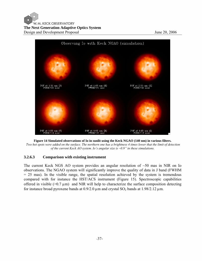
The Next Generation Adaptive Optics System Design and Development Proposal June 20, 2006
-37-
Figure 14 Simulated observations of Io in sunlit using the Keck NGAO (140 nm) in various filters. Two hot spots were added on the surface. The northern one has a brightness 4 times lower that the limit of detection
of the current Keck AO system. Io’s angular size is ~0.9” in these simulations. 3.2.6.3 Comparison with existing instrument
The current Keck NGS AO system provides an angular resolution of ~50 mas in NIR on Io observations. The NGAO system will significantly improve the quality of data in J band (FWHM = 25 mas). In the visible range, the spatial resolution achieved by the system is tremendous compared with for instance the HST/ACS instrument (Figure 15). Spectroscopic capabilities offered in visible (>0.7 μm) and NIR will help to characterize the surface composition detecting for instance broad pyroxene bands at 0.9/2.0 μm and crystal SO2 bands at 1.98/2.12 μm.
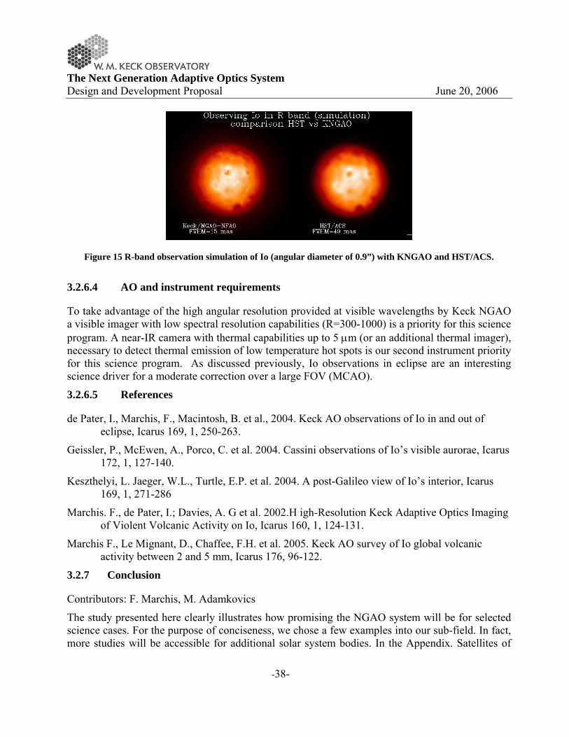
The Next Generation Adaptive Optics System Design and Development Proposal June 20, 2006
-38-
Figure 15 R-band observation simulation of Io (angular diameter of 0.9”) with KNGAO and HST/ACS.
3.2.6.4 AO and instrument requirements
To take advantage of the high angular resolution provided at visible wavelengths by Keck NGAO a visible imager with low spectral resolution capabilities (R=300-1000) is a priority for this science program. A near-IR camera with thermal capabilities up to 5 μm (or an additional thermal imager), necessary to detect thermal emission of low temperature hot spots is our second instrument priority for this science program. As discussed previously, Io observations in eclipse are an interesting science driver for a moderate correction over a large FOV (MCAO).
3.2.6.5 References
de Pater, I., Marchis, F., Macintosh, B. et al., 2004. Keck AO observations of Io in and out of eclipse, Icarus 169, 1, 250-263.
Geissler, P., McEwen, A., Porco, C. et al. 2004. Cassini observations of Io’s visible aurorae, Icarus 172, 1, 127-140.
Keszthelyi, L. Jaeger, W.L., Turtle, E.P. et al. 2004. A post-Galileo view of Io’s interior, Icarus 169, 1, 271-286
Marchis. F., de Pater, I.; Davies, A. G et al. 2002.H igh-Resolution Keck Adaptive Optics Imaging of Violent Volcanic Activity on Io, Icarus 160, 1, 124-131.
Marchis F., Le Mignant, D., Chaffee, F.H. et al. 2005. Keck AO survey of Io global volcanic activity between 2 and 5 mm, Icarus 176, 96-122.
3.2.7 Conclusion
Contributors: F. Marchis, M. Adamkovics
The study presented here clearly illustrates how promising the NGAO system will be for selected science cases. For the purpose of conciseness, we chose a few examples into our sub-field. In fact, more studies will be accessible for additional solar system bodies. In the Appendix. Satellites of

The Next Generation Adaptive Optics System Design and Development Proposal June 20, 2006
-39-
Giant Planets Observable with NGAO, we listed several other satellites, which would be observable considering an on-axis study (using the target itself as a reference) with the NGAO. We considered as a limit the brightness of the satellites but also its distance to the planet removing the ones which are orbiting too close and for which the wavefront analysis analysis will be limited due to the glare of their giant planet. NGAO will be an excellent instrument to map the surface composition of Galilean satellites with a spatial resolution close to (and even better in the visible) than the global Galileo NIMS/SSI observations. Between 6 and 25 element of resolution will be attainable on images of medium-size Saturnian satellites (Enceladus, Mimas, Rhea, Dione, Rhea) providing an opportunity to continue the study currently performed by Cassini spacecraft. A study of giant planet atmospheres is another scientific topic that is not described in this list of science cases. A moderate correction on a large FOV (>45”) (MCAO) will help to characterize the atmospheres of Jupiter and Saturn, studying for instance their activity. The recent discovery of a second red spot on Jupiter illustrates the activity of these atmospheres. The study of these phenomena brings direct constraints on the internal structure, heat flow, and composition of the giant planet atmospheres and thus the evolution of giant planets and exo-planets. The capability of observing moving targets, so the implementation of a differential guiding when the tip-tilt source is not the object itself (and it is moving relatively to the target) must be considered in the design of NGAO. We should also point out that the scientific return of the Keck telescope and the NGAO system will greatly improve if service observing (i.e., queue scheduling) is offered. With an error budget of 140 nm the NGAO system will achieve a SR of ~20% in R-band under moderate seeing conditions. Bright targets like the Galilean satellites (mv~6) can be observed even if the seeing conditions are lower than average in the NIR (>1.2”). Other difficult observations, such as the study of multiple TNOs (mv>17) could be scheduled when the seeing conditions are excellent (<0.7”). Finally, frequent and extremely short (half hour) direct imaging observations of a specific target such as Io, to monitor its activity on a long period of time will be extremely valuable for the scientific project. All these programs could be done more easily if service observing is available at Keck. It will also drastically relax the constraints on the NGAO error budget since it will be possible to take advantage of excellent atmospheric conditions to observe the fainter objects. 3.3 Galactic Science
3.3.1 Introduction
Galactic science has benefited from each successive generation of adaptive optics, from natural guide star AO on 3-4 meter telescopes, then on 8-10 meter class telescopes, to the current single LGS system on Keck. The impact of AO science has been broad, ranging from the studying the formation properties of young stars, detection and characterization of circumstellar disks, and measuring the mass of the super massive black hole at our Galaxy's Center. While galactic science with AO has been prolific, in fact AO has only been able to tackle a very limited subset of the potential science questions. The small sky coverage of NGS AO has greatly restricted the breadth
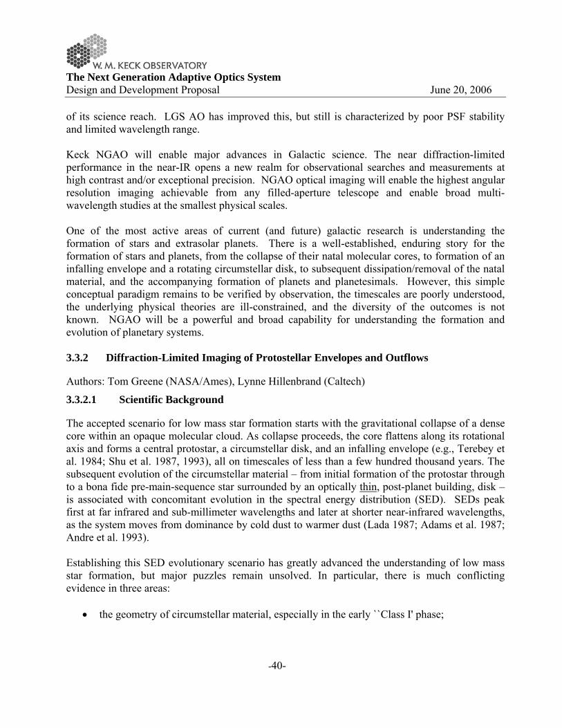
The Next Generation Adaptive Optics System Design and Development Proposal June 20, 2006
-40-
of its science reach. LGS AO has improved this, but still is characterized by poor PSF stability and limited wavelength range. Keck NGAO will enable major advances in Galactic science. The near diffraction-limited performance in the near-IR opens a new realm for observational searches and measurements at high contrast and/or exceptional precision. NGAO optical imaging will enable the highest angular resolution imaging achievable from any filled-aperture telescope and enable broad multi-wavelength studies at the smallest physical scales. One of the most active areas of current (and future) galactic research is understanding the formation of stars and extrasolar planets. There is a well-established, enduring story for the formation of stars and planets, from the collapse of their natal molecular cores, to formation of an infalling envelope and a rotating circumstellar disk, to subsequent dissipation/removal of the natal material, and the accompanying formation of planets and planetesimals. However, this simple conceptual paradigm remains to be verified by observation, the timescales are poorly understood, the underlying physical theories are ill-constrained, and the diversity of the outcomes is not known. NGAO will be a powerful and broad capability for understanding the formation and evolution of planetary systems. 3.3.2 Diffraction-Limited Imaging of Protostellar Envelopes and Outflows
Authors: Tom Greene (NASA/Ames), Lynne Hillenbrand (Caltech)
3.3.2.1 Scientific Background
The accepted scenario for low mass star formation starts with the gravitational collapse of a dense core within an opaque molecular cloud. As collapse proceeds, the core flattens along its rotational axis and forms a central protostar, a circumstellar disk, and an infalling envelope (e.g., Terebey et al. 1984; Shu et al. 1987, 1993), all on timescales of less than a few hundred thousand years. The subsequent evolution of the circumstellar material – from initial formation of the protostar through to a bona fide pre-main-sequence star surrounded by an optically thin, post-planet building, disk – is associated with concomitant evolution in the spectral energy distribution (SED). SEDs peak first at far infrared and sub-millimeter wavelengths and later at shorter near-infrared wavelengths, as the system moves from dominance by cold dust to warmer dust (Lada 1987; Adams et al. 1987; Andre et al. 1993). Establishing this SED evolutionary scenario has greatly advanced the understanding of low mass star formation, but major puzzles remain unsolved. In particular, there is much conflicting evidence in three areas:
• the geometry of circumstellar material, especially in the early ``Class I' phase;

The Next Generation Adaptive Optics System Design and Development Proposal June 20, 2006
-41-
• the accretion mechanism and resulting properties of the central stars themselves, again, especially in the early “Class I” phase;
• the origin and nature of material that is outflowing in jets and winds.
Seeing-limited images at I-band (Eisner et al. 2005) and in the near-IR (Tamura et al. 1991; Whitney et al. 1997) have shown that Class I systems in the nearby (d = 140 pc) Taurus-Auriga dark clouds have large, extended circumstellar envelopes which are resolved in scattered light (Figure 16). Model fits to the imaging data along with the spectral energy distributions for these objects indicate that they are surrounded by both massive disks and envelopes, with envelope matter infalling at high rates. Recent optical (White & Hillenbrand 2004) and near-IR (Doppmann et al. 2005) high resolution spectroscopic studies have confirmed that the central stars of some Class I objects appear to be accreting matter from the disk onto the star at the high rates expected from infalling envelope material, but many others are not, suggesting that disks may have widely varying (and perhaps episodic) accretion rates.
Figure 16 Seeing-limited (0.5-0.6”) I-band (0.8 μm) images of protostars in Taurus-Auriga The resolved scattered light structure from the circumstellar environment is shown (Eisner et al., 2005). Each image
is 30” on a side, with the “+” symbol indicating the centroid of the mm-continuum dust emission.
3.3.2.2 Proposed observations and targets
Diffraction-limited AO imaging with Keck would help greatly in resolving the protostellar/circumstellar environment and its connection to the early evolution of the young stars themselves. Existing model fits are not well constrained (Eisner et al. 2005), hampered by seeing-limited spatial resolution and limited wavelength coverage. In particular, multi-color high

The Next Generation Adaptive Optics System Design and Development Proposal June 20, 2006
-42-
resolution AO observations from visible-to-near-IR wavelengths would help separate the effects of grain properties (size, composition) from those of the envelope density distributions. Resolved optical and near-infrared imaging from Keck NGAO can be combined with integrated-light SEDs and resolved sub-mm/mm interferometric imaging (e.g. from CARMA and ALMA) to constrain better the physical properties of the circumstellar environment such as the viewing inclination, disk mass, outer size, mass accretion rate, and disk scale height (Figure 17). The ability to make AO assisted polarization measurements would further improve the uniqueness of model fits (Whitney et al. 1997), providing more certainty to the nature of these objects. Furthermore, mid-IR AO spectroscopy would trace the spatial distribution of grain properties in the disk and enable a new level of geometric modeling. Finally, high dispersion AO spectroscopy would enable study of both infalling and outflowing material at these early stages. In particular, the kinematics of the outflows are relatively unprobed, but observable with Keck NGAO at the spatial scales necessary to separate continuum from various line emission regions, e.g. H2 and [FeII] in the near-infrared or [SII] and [OI] in the optical.
Figure 17 Integrated-light SEDs. I-band scattered light images, and millimeter continuum images for a flared disk model at a range of viewing angles (i increases from the bottom to top panels). More edge-on models exhibit deeper absorption at mid-IR wavelengths
and higher extinction of the central star. For small inclinations (i ~ 30), the central star is visible and dominates the I-band emission. For moderate inclinations an asymmetric scattered light structure is observed, while for nearly edge-
on orientations a symmetric, double-lobed structure is observed (from Eisner et al. 2005). More importantly, stable diffraction-limited imaging would extend studies from the handful of Class I objects in Taurus-Auriga that have been studied thus far to many more in the more distant ρ Oph, Serpens, and Perseus (140 - 330 pc) regions as well as the even further regions which are undergoing high mass star formation. This would allow some of the first direct measurements of
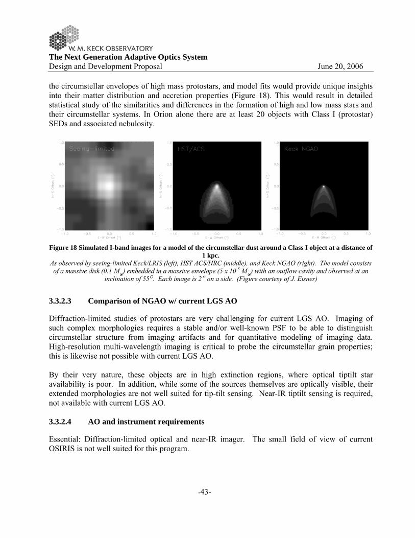
The Next Generation Adaptive Optics System Design and Development Proposal June 20, 2006
-43-
the circumstellar envelopes of high mass protostars, and model fits would provide unique insights into their matter distribution and accretion properties (Figure 18). This would result in detailed statistical study of the similarities and differences in the formation of high and low mass stars and their circumstellar systems. In Orion alone there are at least 20 objects with Class I (protostar) SEDs and associated nebulosity.
Figure 18 Simulated I-band images for a model of the circumstellar dust around a Class I object at a distance of
1 kpc. As observed by seeing-limited Keck/LRIS (left), HST ACS/HRC (middle), and Keck NGAO (right). The model consists of a massive disk (0.1 M ) embedded in a massive envelope (5 x 10⁻³ M ) with an outflow cavity and observed at an
inclination of 55 . Each image is 2” on a side. (Figure courtesy of J. Eisner)
3.3.2.3 Comparison of NGAO w/ current LGS AO
Diffraction-limited studies of protostars are very challenging for current LGS AO. Imaging of such complex morphologies requires a stable and/or well-known PSF to be able to distinguish circumstellar structure from imaging artifacts and for quantitative modeling of imaging data. High-resolution multi-wavelength imaging is critical to probe the circumstellar grain properties; this is likewise not possible with current LGS AO. By their very nature, these objects are in high extinction regions, where optical tiptilt star availability is poor. In addition, while some of the sources themselves are optically visible, their extended morphologies are not well suited for tip-tilt sensing. Near-IR tiptilt sensing is required, not available with current LGS AO. 3.3.2.4 AO and instrument requirements
Essential: Diffraction-limited optical and near-IR imager. The small field of view of current OSIRIS is not well suited for this program.

The Next Generation Adaptive Optics System Design and Development Proposal June 20, 2006
-44-
Desirable but not absolutely essential: Imaging polarimetry, near-IR echelle spectroscopy, mid-IR spectroscopy. 3.3.2.5 References
Adams, F. C., Lada, C. J., & Shu, F. H. 1987, ApJ, 312, 788
André, P., Ward-Thompson, D., & Barsony, N. 1993, ApJ, 406, 122
Doppmann, G. W., Greene, T. P., Covey, K. R., Lada, C. J. 2005, AJ, 130, 1145
Eisner, J. A., Hillenbrand, L. A., Carpenter, J. M., & Wolf, S. 2005, ApJ, 635, 396
Lada, C. J.. 1987, IAU Symp. 115: Star Forming Regions, 115, 1
Shu, F. H., Adams, F. C., & Lizano, S. 1987, Ann Rev Astron & Astrophys, 25, 23
Shu, F. H., Najita, J., Galli, D., Ostriker, E., & Lizano, S. 1993, in Protostars and Planets III, 3
Tamura, M., Gatley, I., Waller, W., & Werner, M. W. 1991, ApJL, 374, L25
Terebey, S., Shu, F. H., & Cassen, P. 1984, ApJ, 286, 529
White, R. J., & Hillenbrand, L. A. 2004, ApJ, 616, 998
Whitney, B. A. Kenyon, S. J., Gomez, M. 1997, ApJ, 485, 703
3.3.3 Imaging and Characterization of Extrasolar Planets
Authors: Michael Liu (IfA/Hawaii), Bruce Macintosh (IGPP/LLNL)
3.3.3.1 Scientific Background
The last decade has witnessed a revolution in astronomy with the discovery and characterization of substellar objects, brown dwarfs and extrasolar planets. The next 10 years promise to be even more rewarding. Observational capabilities are now on the horizon for direct detection of these objects and hence for determining the diversity of planetary systems around other stars. The Keck Telescope has played a major role in these discoveries, primarily through radial velocity surveys. While these studies have been very successful at finding extrasolar planets, such discoveries are inherently limited since they measure only the orbital properties and lower limits on the masses. Direct imaging would allow us to measure colors, luminosities and spectra, thereby probing temperatures and compositions. At relatively young ages (<~1 Gyr), Jupiter-mass planets continue to radiate their internal heat at near-IR wavelengths far above their expected blackbody emission, and thus are amenable to direct imaging. By virtue of its unparalleled 10-meter primary mirror, Keck adaptive optics imaging can produce the highest angular resolution images of any telescope in existence. The next generation of discoveries require with AO systems that produce much higher contrast (the ability to detect faint

The Next Generation Adaptive Optics System Design and Development Proposal June 20, 2006
-45-
objects next to bright ones), greater PSF stability, and broader wavelength coverage. Both the Gemini and VLT observatories are developing ``extreme AO systems'' (ExAO) to achieve very high contrast images for direct imaging of planets around nearby, young solar-type stars. While very powerful, such systems are by their nature restricted to bright stars (I <~ 8-9 mags) and thus address only a portion of the physical parameter space. 3.3.3.2 Proposed observations and targets
3.3.3.2.1 Planets around low-mass stars and brown dwarfs
Direct imaging of substellar companions (brown dwarfs and extrasolar planets) is substantially easier around lower mass primaries, since the required contrast ratios are smaller for a given companion mass. Indeed, the first bona fide L dwarf and T dwarfs were discovered as companions to low-mass stars (Becklin & Zuckerman 1988, Nakajima et al 1995). Thus, searching for low-mass stars and brown dwarfs is an appealing avenue for planet detection and characterization. Given that low-mass stars are so much more abundant than higher mass stars, they might constitute the most common hosts of planetary systems. Keck NGAO will be a significant advance from previous imaging surveys, reaching much lower companion masses and correspondingly much cooler temperatures. These targets are optically faint, and thus unobservable with current or future NGS/ExAO systems. Current single-LGS systems are only able to reach modest contrast ratios at K-band. Direct detection is more favorable at J and H-bands, where planetary mass companions are brighter and higher angular resolution can be achieved; good performance at these wavelengths is only possible with Keck NGAO. One very low-mass companion, 2MASS 1207-39B, has recently been directly imaged around a young (~10 Myr) field brown dwarf (~25 MJup), with an estimated mass of ~5 MJup and a projected separation of 60 AU (Chauvin et al 2005). The incidence of similar systems is unknown; given that 2M1207~B was found in a search of only two objects, it is promising that many more wide, planetary companions to brown dwarfs. Discovery of Jovian-mass companions around brown dwarfs would be difficult to explain in conventional theories where planets form in circumstellar disk. While disks around common around young brown dwarfs (e.g., Liu et al 2003), they are unlikely to be massive enough to form such companions (Klein et al 2003). But regardless of their origin, such planetary-mass companions would constitute relatively easily observed systems for studying the spectral characteristics of planetary atmospheres.

The Next Generation Adaptive Optics System Design and Development Proposal June 20, 2006
-46-
Figure 19 JHK color image of the 2MASS 1207-3932 system. As observed with the VLT NGS system equipped with a near-IR wavefront sensor (Chauvin et al 2005). The primary is a young brown dwarf, with an estimated age of ~12 Myr and ~25 MJup. The companion has an estimated mass of only ~5 MJup. Only a
small number of brown dwarfs can be imaged with sufficient sensitivity and angular resolution with current LGS AO to detect Jovian-mass companions. Keck NGAO will be a major advance for detection and characterization of planets around low-mass
stars and brown dwarfs.
Spectroscopic follow-up of the coldest companions will be an important path in characterizing the atmospheres of objects in the planetary domain. Strong molecular absorption features from water and methane provide diagnostics of temperature and surface gravity at modest (R~100) resolution. Below ~500 K, water clouds are expected to form and may mark the onset of a new spectral class, a.k.a. ``Y dwarfs''. Such objects represent the missing link between the known T dwarfs and Jupiter, but are probably too faint and rare to be detected as free-floating objects in shallow all-sky surveys such as 2MASS and SDSS. Furthermore, the coolest/lowest mass objects may not exist as free-floating objects if there is a low-mass cutoff to the initial mass function of the star formation process, e.g., from opacity-limited fragmentation of molecular clouds (Mmin ~ 5-10 MJup; Silk 1977). Even cooler/lower mass objects might only form via fragmentation, akin to the formation of binary stars, and only be found as companions.
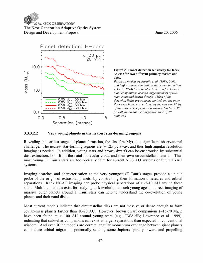
The Next Generation Adaptive Optics System Design and Development Proposal June 20, 2006
-47-
Figure 20 Planet detection sensitivity for Keck NGAO for two different primary masses and ages. Based on models by Baraffe et al. (1998, 2003) and high contrast simulations described in section 4.3.2.7. NGAO will be able to search for Jovian-mass companions around large numbers of low-mass stars and brown dwarfs. (Most of the detection limits are contrast-limited, but the outer floor seen in the curves is set by the raw sensitivity of the system. The primary is assumed to be at 30 pc with an on-source integration time of 20 minutes.)
3.3.3.2.2 Very young planets in the nearest star-forming regions
Revealing the earliest stages of planet formation, the first few Myr, is a significant observational challenge. The nearest star-forming regions are >~125 pc away, and thus high angular resolution imaging is needed. In addition, young stars and brown dwarfs can be enshrouded by substantial dust extinction, both from the natal molecular cloud and their own circumstellar material. Thus most young (T Tauri) stars are too optically faint for current NGS AO systems or future ExAO systems. Imaging searches and characterization at the very youngest (T Tauri) stages provide a unique probe of the origin of extrasolar planets, by constraining their formation timescales and orbital separations. Keck NGAO imaging can probe physical separations of >~5-10 AU around these stars. Multiple methods exist for studying disk evolution at such young ages --- direct imaging of massive outer planets around T Tauri stars can help to understand the co-evolution of young planets and their natal disks. Most current models indicate that circumstellar disks are not massive or dense enough to form Jovian-mass planets farther than 10-20 AU. However, brown dwarf companions (~15-70 MJup) have been found at >~100 AU around young stars (e.g., TWA-5B; Lowrance et al. 1999), indicating that substellar companions can exist at larger separations than expected in conventional wisdom. And even if the models are correct, angular momentum exchange between giant planets can induce orbital migration, potentially sending some Jupiters spirally inward and propelling
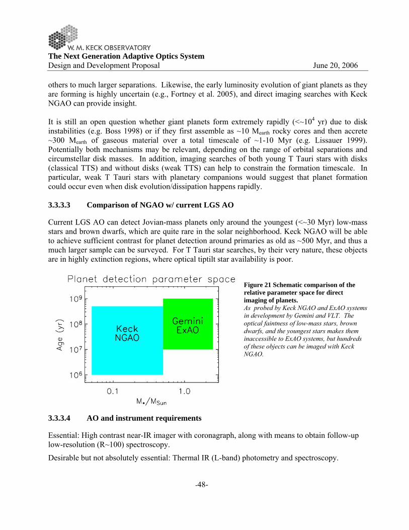
The Next Generation Adaptive Optics System Design and Development Proposal June 20, 2006
-48-
others to much larger separations. Likewise, the early luminosity evolution of giant planets as they are forming is highly uncertain (e.g., Fortney et al. 2005), and direct imaging searches with Keck NGAO can provide insight. It is still an open question whether giant planets form extremely rapidly (<~104 yr) due to disk instabilities (e.g. Boss 1998) or if they first assemble as ~10 Mearth rocky cores and then accrete ~300 Mearth of gaseous material over a total timescale of ~1-10 Myr (e.g. Lissauer 1999). Potentially both mechanisms may be relevant, depending on the range of orbital separations and circumstellar disk masses. In addition, imaging searches of both young T Tauri stars with disks (classical TTS) and without disks (weak TTS) can help to constrain the formation timescale. In particular, weak T Tauri stars with planetary companions would suggest that planet formation could occur even when disk evolution/dissipation happens rapidly. 3.3.3.3 Comparison of NGAO w/ current LGS AO
Current LGS AO can detect Jovian-mass planets only around the youngest (<~30 Myr) low-mass stars and brown dwarfs, which are quite rare in the solar neighborhood. Keck NGAO will be able to achieve sufficient contrast for planet detection around primaries as old as ~500 Myr, and thus a much larger sample can be surveyed. For T Tauri star searches, by their very nature, these objects are in highly extinction regions, where optical tiptilt star availability is poor.
Figure 21 Schematic comparison of the relative parameter space for direct imaging of planets. As probed by Keck NGAO and ExAO systems in development by Gemini and VLT. The optical faintness of low-mass stars, brown dwarfs, and the youngest stars makes them inaccessible to ExAO systems, but hundreds of these objects can be imaged with Keck NGAO.
3.3.3.4 AO and instrument requirements
Essential: High contrast near-IR imager with coronagraph, along with means to obtain follow-up low-resolution (R~100) spectroscopy.
Desirable but not absolutely essential: Thermal IR (L-band) photometry and spectroscopy.

The Next Generation Adaptive Optics System Design and Development Proposal June 20, 2006
-49-
3.3.4 Next-Generation Debris Disk Science
Authors: Stanimir Metchev (UCLA) and Michael Liu (IfA/Hawaii)
3.3.4.1 Scientific Background
After dissipation of their primordial planet-forming disks of gas and dust, many stars possess debris disks (e.g. Backman & Paresce 1993; Rieke et al. 2005). The dust in debris disks is continually generated from collisions of larger parent bodies that are otherwise undetectable. These parent bodies are the detritus of the planet formation process, and debris disk systems as a whole represent the extrasolar analogs of the asteroid belt and Kuiper Belt in our own solar system. Theory predicts that planet growth and disk dissipation are intimately linked (e.g., Lissauer 1993). During the post-T Tauri stages of stellar evolution (~10-100 Myr), simulations show that significant debris can arise from large stochastic collisions (e.g., the Earth-Moon formation event) and/or gravitational stirring by recently formed small (Pluto-sized) rocky planets (Kenyon & Bromley 2004). In addition, dynamical interactions between planets and the remaining dust and planetesimals are expected to perturb the orbits of the smaller bodies and to imprint characteristic signatures on the spatial distribution of circumstellar dust (e.g., Roques et al. 1994; Wyatt et al. 1999; Kuchner & Holman 2003); the high prevalence of ring-like and/or clumpy structures seen in scattered light images of debris disks lends supports to this idea (Figure 1). Thus, there is an intimate connection between debris disks and the larger unseen planetesimals and planets that constitute extrasolar planetary systems. A small fraction of the brightest (Ldust/Lstar >~ 10-4), nearest debris disks found by IRAS and ISO have been spatially resolved in scattered light at optical and near-IR wavelengths with HST and/or ground-based natural guide star AO systems. The information gained from these few spatially resolved observations has greatly enhanced our knowledge of the structure of debris disks (e.g., Schneider et al. 1999; Golimowski et al. 2006) and of the physical properties of their constituent dust grains (e.g. Artymowicz 1990; Li & Lunine 2003). The limited data have also posed numerous new questions regarding disk evolution and morphology, such as:
• How do primordial disks transition into debris disks?
• What is the role of planets in this transition?
• How do planets interact with the disks in which they are embedded?
• How significant are stochastic collisions in establishing debris disk properties?
Only about a dozen debris disks have been spatially resolved to date and with limited wavelength coverage --- thus we have only begun to address these central questions. These can be pursued with Keck NGAO through two complementary paths: (1) greatly expanding the resolved census of debris disks and (2) more intensive, multi-wavelength studies of currently resolved systems.
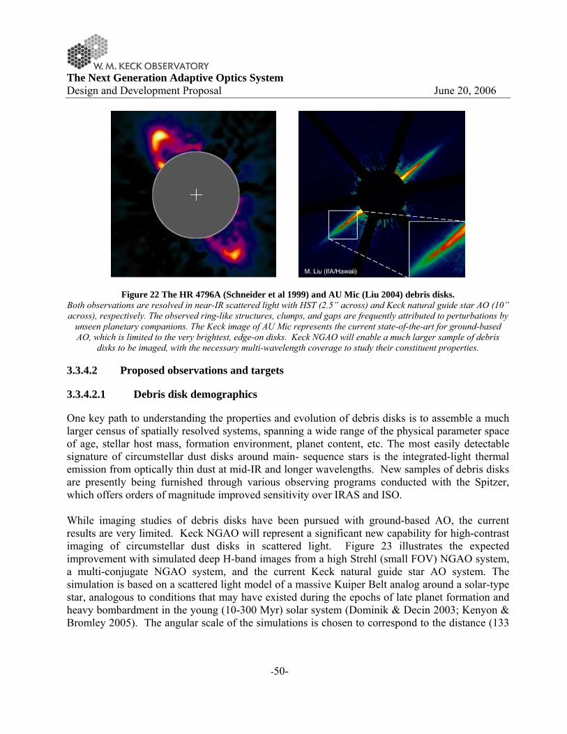
The Next Generation Adaptive Optics System Design and Development Proposal June 20, 2006
-50-
Figure 22 The HR 4796A (Schneider et al 1999) and AU Mic (Liu 2004) debris disks. Both observations are resolved in near-IR scattered light with HST (2.5” across) and Keck natural guide star AO (10” across), respectively. The observed ring-like structures, clumps, and gaps are frequently attributed to perturbations by
unseen planetary companions. The Keck image of AU Mic represents the current state-of-the-art for ground-based AO, which is limited to the very brightest, edge-on disks. Keck NGAO will enable a much larger sample of debris
disks to be imaged, with the necessary multi-wavelength coverage to study their constituent properties.
3.3.4.2 Proposed observations and targets
3.3.4.2.1 Debris disk demographics
One key path to understanding the properties and evolution of debris disks is to assemble a much larger census of spatially resolved systems, spanning a wide range of the physical parameter space of age, stellar host mass, formation environment, planet content, etc. The most easily detectable signature of circumstellar dust disks around main- sequence stars is the integrated-light thermal emission from optically thin dust at mid-IR and longer wavelengths. New samples of debris disks are presently being furnished through various observing programs conducted with the Spitzer, which offers orders of magnitude improved sensitivity over IRAS and ISO. While imaging studies of debris disks have been pursued with ground-based AO, the current results are very limited. Keck NGAO will represent a significant new capability for high-contrast imaging of circumstellar dust disks in scattered light. Figure 23 illustrates the expected improvement with simulated deep H-band images from a high Strehl (small FOV) NGAO system, a multi-conjugate NGAO system, and the current Keck natural guide star AO system. The simulation is based on a scattered light model of a massive Kuiper Belt analog around a solar-type star, analogous to conditions that may have existed during the epochs of late planet formation and heavy bombardment in the young (10-300 Myr) solar system (Dominik & Decin 2003; Kenyon & Bromley 2005). The angular scale of the simulations is chosen to correspond to the distance (133
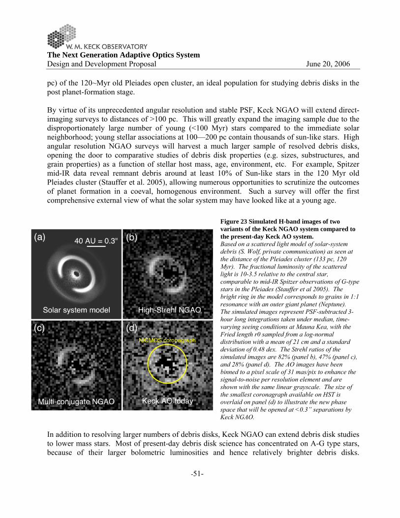
The Next Generation Adaptive Optics System Design and Development Proposal June 20, 2006
-51-
pc) of the 120~Myr old Pleiades open cluster, an ideal population for studying debris disks in the post planet-formation stage. By virtue of its unprecedented angular resolution and stable PSF, Keck NGAO will extend direct-imaging surveys to distances of >100 pc. This will greatly expand the imaging sample due to the disproportionately large number of young (<100 Myr) stars compared to the immediate solar neighborhood; young stellar associations at 100—200 pc contain thousands of sun-like stars. High angular resolution NGAO surveys will harvest a much larger sample of resolved debris disks, opening the door to comparative studies of debris disk properties (e.g. sizes, substructures, and grain properties) as a function of stellar host mass, age, environment, etc. For example, Spitzer mid-IR data reveal remnant debris around at least 10% of Sun-like stars in the 120 Myr old Pleiades cluster (Stauffer et al. 2005), allowing numerous opportunities to scrutinize the outcomes of planet formation in a coeval, homogenous environment. Such a survey will offer the first comprehensive external view of what the solar system may have looked like at a young age.
Figure 23 Simulated H-band images of two variants of the Keck NGAO system compared to the present-day Keck AO system. Based on a scattered light model of solar-system debris (S. Wolf, private communication) as seen at the distance of the Pleiades cluster (133 pc, 120 Myr). The fractional luminosity of the scattered light is 10-3.5 relative to the central star, comparable to mid-IR Spitzer observations of G-type stars in the Pleiades (Stauffer et al 2005). The bright ring in the model corresponds to grains in 1:1 resonance with an outer giant planet (Neptune). The simulated images represent PSF-subtracted 3-hour long integrations taken under median, time-varying seeing conditions at Mauna Kea, with the Fried length r0 sampled from a log-normal distribution with a mean of 21 cm and a standard deviation of 0.48 dex. The Strehl ratios of the simulated images are 82% (panel b), 47% (panel c), and 28% (panel d). The AO images have been binned to a pixel scale of 31 mas/pix to enhance the signal-to-noise per resolution element and are shown with the same linear grayscale. The size of the smallest coronagraph available on HST is overlaid on panel (d) to illustrate the new phase space that will be opened at <0.3” separations by Keck NGAO.
In addition to resolving larger numbers of debris disks, Keck NGAO can extend debris disk studies to lower mass stars. Most of present-day debris disk science has concentrated on A-G type stars, because of their larger bolometric luminosities and hence relatively brighter debris disks.

The Next Generation Adaptive Optics System Design and Development Proposal June 20, 2006
-52-
However, very little is known about debris disks around M dwarfs, as only a handful of examples have been identified. Past IRAS and ISO searches for debris disks have largely neglected and/or overlooked low-mass stars, due to sensitivity limitations and choice of science focus. The greater far-IR sensitivity of Spitzer will enable more debris disks around late-type stars to be discovered. These will be prime targets for future investigations in scattered light with the Keck NGAO system, as their primary stars will be too faint for high contrast natural guide star AO. The scientific potential of the M dwarfs is demonstrated by the young star AU Mic, the first identified M dwarf debris disk system (Liu et al 2004; Kalas, Liu & Matthews 2004). Adaptive optics near-IR and HST optical imaging achieves a spatial resolution of 0.4~AU (Liu 2004; Krist et al. 2005a; Metchev et al. 2005) and reveals a rich variety of substructure, suggestive of planetary companions. Disks around substellar objects are also potential science targets for high-contrast, high-angular resolution imaging. Indeed, ground-based and space-based IR photometric studies have already identified many, optically thick disks around young brown dwarfs in the nearest (~150 pc) star-forming regions (e.g. Liu et al 2003; Luhman et al. 2005). Spatially resolved imaging of their disks, which is expected to be within the resolving power of the Keck NGAO system in the visible, will open a window into studying the properties and evolution of circum-sub-stellar disks. 3.3.4.2.2 Evolution of low-mass planets and planetesimals
Intensive study of the most observable (nearest and brightest) systems is an important means to advance our understanding of debris disks. Spatially resolved high-contrast, multi-wavelength imaging offers a unique opportunity to study their circumstellar material and their embedded low-mass planets. High resolution Keck NGAO optical imaging will be a powerful diagnostic tool. Scattered light imaging studies are best performed at shorter wavelengths, where the lower sky brightness and favorable scattering properties of sub-micron dust grains allows optimal imaging contrast between the parent star and the circumstellar dust. However, previous ground-based AO observations of debris disks have mostly focused on H-band observations, a necessary compromise since current AO performance at shorter wavelengths is poor. Keck NGAO will overcome this limitation, enabling near diffraction-limited imaging in the optical (~0.015”) with modest Strehl ratios, providing the very highest possible angular resolution. NGAO optical imaging will be a powerful means to identify and diagnose the substructure in debris disks. This new capability can reveal dynamical signatures (rings, gaps) in disks due to embedded planets out to three times greater distances than previous studies. Similarly, it will allow scrutiny over smaller physical scales around nearby systems. The majority of resolved debris disks to date show substructure down to the limit of detectability, suggesting that even higher angular resolution imaging will be fruitful. Such embedded low-mass planets (~Neptune) have too large orbital separations to be detectable by radial velocity surveys and are too faint to be

The Next Generation Adaptive Optics System Design and Development Proposal June 20, 2006
-53-
directly imaged. Hence, observation and theoretical modeling of disk substructure is a unique probe of the outer regions of other solar systems. An additional benefit of visible AO imaging studies arises from the relation between the scattering properties of grains and their size. Grain scattering efficiency peaks for incoming radiation of wavelength λ ∼ 2πa, where a is the grain diameter. By extending the capabilities of the Keck NGAO to wavelengths as short as 0.6 μm, we would gain sensitivity to circumstellar grains as small as 0.1 μm. Such small grains are common in primordial circumstellar disks and may dominate the outskirts of the debris disk around late-type stars, where they are blown on highly eccentric orbits by stellar radiation pressure (e.g. Augereau et al. 2001, 2006; Strubbe & Chiang 2006). Visible-wavelength AO capability on Keck will thus be an important asset for measuring the outer radii of these extrasolar Kuiper Belt analogs, an elusive parameter that is often difficult to constrain from long wavelength far-IR/mm unresolved observations. Finally, Keck NGAO near-IR data will provide an excellent match in angular resolution and contrast with HST optical, enabling high precision multi-wavelength color measurements. Such data are sensitive to the grain size distribution, porosity and composition; spatially resolved maps will allow for comparative studies of the properties of circumstellar material in different systems. Sub-mm resolved imaging from ALMA of the brightest systems traces the dust emission properties, providing complementary information to scattered light data. The value of such studies resides not just in ascertaining the properties of the dust grains. Such measurements are needed to ascertain the physical effects acting on the grains, which depend on the grain sizes, and thus are crucial in attempting to understand the linkage between disk substructure and embedded low-mass planets. 3.3.4.3 Comparison of NGAO w/ current LGS AO
Current debris disk studies with natural guide star AO are limited to only the brightest, edge-on disks, and current LGS AO does not have sufficient Strehl or PSF stability. Keck NGAO will provide a precise, stable PSF for high contrast imaging in the near-IR, suitable for detecting fainter, smaller and or non-edge-on systems. Keck NGAO will also add diffraction-limited imaging in the optical, a novel and powerful capability. 3.3.4.4 AO and instrument requirements
Essential: Near-IR and optical imagers.
Desirable but not absolutely essential: Polarimetry, PSF reconstruction from AO telemetry, near-IR detector with substantially lower read noise and/or more dynamic range than NIRC2.
3.3.4.5 References
Artymowicz et al. 1990, Advances in Space Research, 10, 81

The Next Generation Adaptive Optics System Design and Development Proposal June 20, 2006
-54-
Backman, D. E., & Paresce, F. 1993, in Protostars and Planets III, 1253--1304
Beichman, C. A., et al. 2005, ApJ, 622, 1160
Decin, G. et al. 2003, ApJ, 598, 636
Dominik, C. & Decin, G. 2003, ApJ, 598, 626
Els, S. G. et al. 2001, A&A, 370, L1
Kalas, P., Liu, M. C., & Matthews, B. C. 2004, Science, 303, 1990
Kenyon, S. J. & Bromley, B. C. 2005, AJ, 130, 269
Kim, J. S., et al. 2005, ApJ, 632, 659
Krist, J. E. et al. 2005, AJ, 129, 1008
Li, A. & Lunine, J. I. 2003, ApJ, 590, 368
Liou, J. & Zook, H. A. 1999, AJ, 118, 580
Lissauer, J. J. 1993, ARAA, 31, 129
Liu, M. C. 2004, Science, 305, 1442
Liu, M. C. et al. 2004, ApJ, 608, 528
Luhman, K. L., et al. 2005, ApJL, 631, L69
Metchev, S. A., et al. 2005, ApJ, 622, 451
Plavchan, P., Jura, M., & Lipscy, S. J. 2005, ApJ, 631, 1161
Plets, H. & Vynckier, C. 1999, A&A, 343, 496
Roques, F. et al. 1994, Icarus, 108, 37
Schneider, G., et al. 1999, ApJL, 513, L127
Stauffer, J. R., et al. 2005, AJ, 130, 1834
Wyatt et al. 1999, ApJ, 527, 918

The Next Generation Adaptive Optics System Design and Development Proposal June 20, 2006
-55-
3.3.5 The Galactic Center: Black Holes, General Relativity, and Dark Matter
Authors: Nevin Weinberg (UCSB), Andrea Ghez (UCLA), Jessica Lu (UCLA)
3.3.5.1 Scientific Background
The proximity of our Galaxy's center presents a unique opportunity to study a massive black hole (BH) and its environs at much higher spatial resolution than can be brought to bear on any other galaxy. In the last decade, near-IR observations with astrometric precisions of 1 mas have enabled the measurement of orbital motions for several stars near the Galactic center (GC), revealing a central dark mass of ~4 x 10⁶ MSun (Ghez et al. 2003, Ghez et al. 2005; Schodel et al. 2002; Schodel et al. 2003). Radio VLBA observations have now resolved the central object to within several multiples of the event horizon, indicating that the central mass is confined to a radius smaller than 1 AU (Shen et al. 2005). These observations provide the most definitive evidence for the existence of massive BHs in the centers of galaxies. The orbital motions now also provide the most accurate measurement of the GC distance R0, constraining it to within a few percent (Eisenhauer et al. 2003). Due to the crowded stellar environment at the GC and the strong line-of-sight optical absorption, tracking the stellar orbits requires the high angular resolution, near-IR imaging capabilities of adaptive optics on telescopes with large primary mirrors, such as Keck. Though the current orbital reconstructions are consistent with pure Keplerian motion, with improved astrometric and radial velocity precision, deviations from pure Keplerian motion are expected. As we show, with Keck NGAO we can detect the deviations from a variety of effects. These will provide a unique laboratory for probing the dynamics of galactic nuclei, the properties of exotic dark matter, and the mass function of stellar-mass black holes. They will also provide the first tests of general relativity in the high mass, strong gravity, regime. Keck NGAO will measure these non-Keplerian motions to precisions that will not be greatly surpassed even in the era of extremely large (~30m) telescopes. The wealth of information gained from a decade of GC imaging at high angular resolution has also yielded numerous puzzles related to the stars themselves and the accretion physics of the central BH. In particular: (1) how did the monitored stars, whose spectral features suggest that they are young (< 10 Myr), come to reside in a region so close to the massive BH and thus so inhospitable to star formation? (2) Why is the emission from the accreting central BH, as measured by multiwavelength imaging of SgrA*, so dim compared to that of massive BHs at the center of other galaxies, and what is the origin of the large flaring behavior, seen most readily in the IR? These questions relate to the more global issues of galaxy formation and massive BH growth and their complicated interplay with star formation in dense galactic nuclei. We show that with the unparalleled imaging capabilities of Keck NGAO, they can be directly addressed.
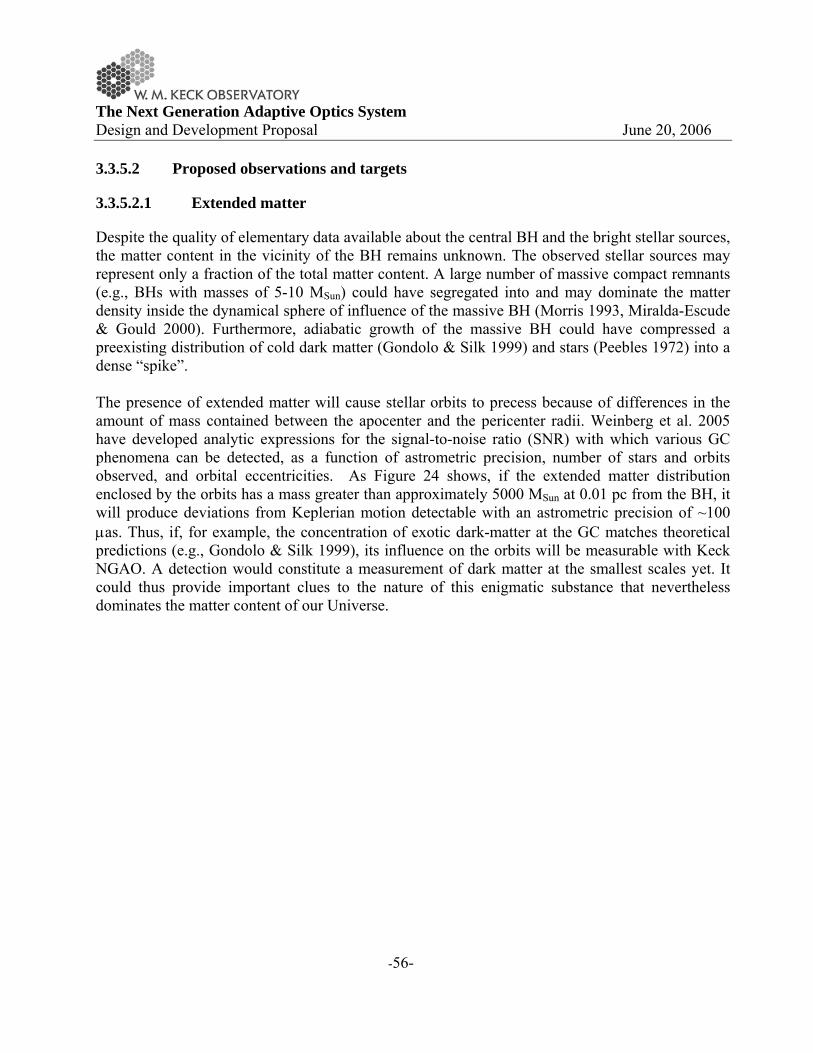
The Next Generation Adaptive Optics System Design and Development Proposal June 20, 2006
-56-
3.3.5.2 Proposed observations and targets
3.3.5.2.1 Extended matter
Despite the quality of elementary data available about the central BH and the bright stellar sources, the matter content in the vicinity of the BH remains unknown. The observed stellar sources may represent only a fraction of the total matter content. A large number of massive compact remnants (e.g., BHs with masses of 5-10 MSun) could have segregated into and may dominate the matter density inside the dynamical sphere of influence of the massive BH (Morris 1993, Miralda-Escude & Gould 2000). Furthermore, adiabatic growth of the massive BH could have compressed a preexisting distribution of cold dark matter (Gondolo & Silk 1999) and stars (Peebles 1972) into a dense “spike”. The presence of extended matter will cause stellar orbits to precess because of differences in the amount of mass contained between the apocenter and the pericenter radii. Weinberg et al. 2005 have developed analytic expressions for the signal-to-noise ratio (SNR) with which various GC phenomena can be detected, as a function of astrometric precision, number of stars and orbits observed, and orbital eccentricities. As Figure 24 shows, if the extended matter distribution enclosed by the orbits has a mass greater than approximately 5000 MSun at 0.01 pc from the BH, it will produce deviations from Keplerian motion detectable with an astrometric precision of ~100 μas. Thus, if, for example, the concentration of exotic dark-matter at the GC matches theoretical predictions (e.g., Gondolo & Silk 1999), its influence on the orbits will be measurable with Keck NGAO. A detection would constitute a measurement of dark matter at the smallest scales yet. It could thus provide important clues to the nature of this enigmatic substance that nevertheless dominates the matter content of our Universe.
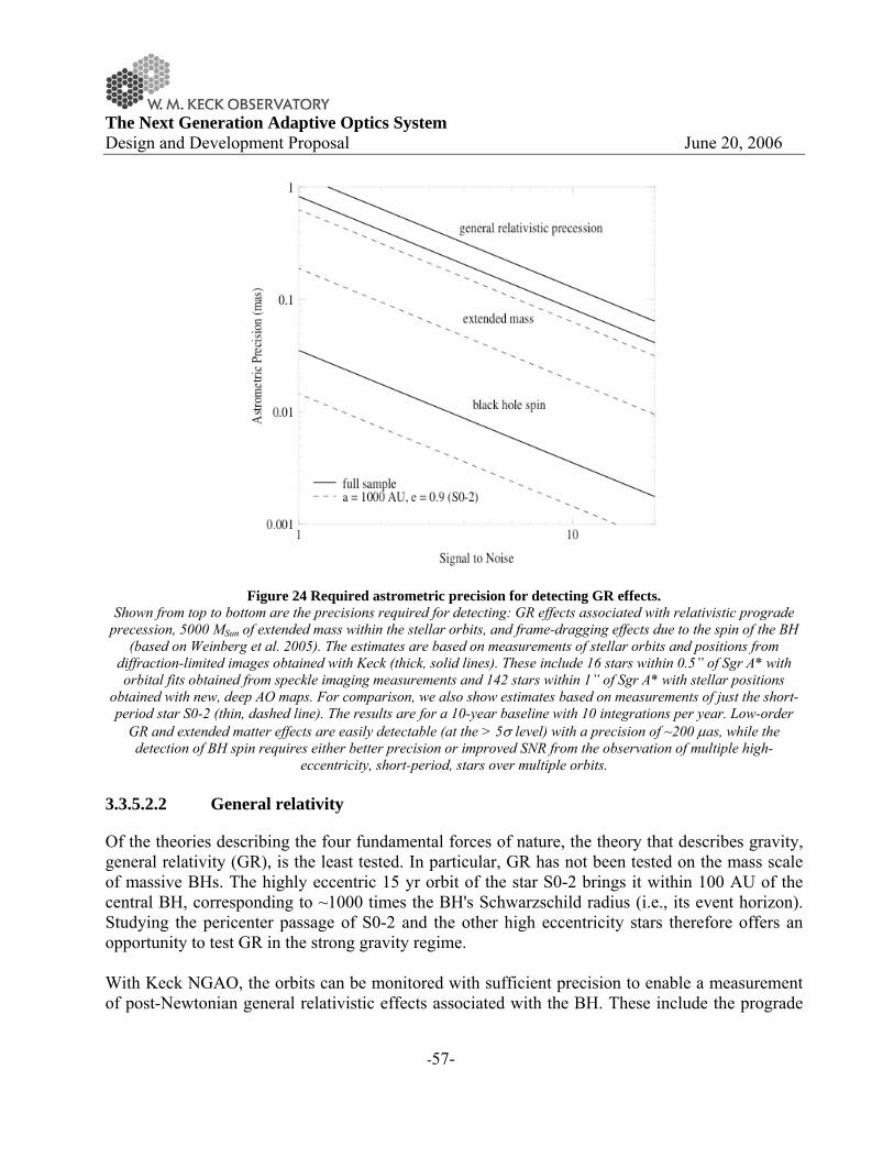
The Next Generation Adaptive Optics System Design and Development Proposal June 20, 2006
-57-
Figure 24 Required astrometric precision for detecting GR effects. Shown from top to bottom are the precisions required for detecting: GR effects associated with relativistic prograde
precession, 5000 MSun of extended mass within the stellar orbits, and frame-dragging effects due to the spin of the BH (based on Weinberg et al. 2005). The estimates are based on measurements of stellar orbits and positions from
diffraction-limited images obtained with Keck (thick, solid lines). These include 16 stars within 0.5” of Sgr A* with orbital fits obtained from speckle imaging measurements and 142 stars within 1” of Sgr A* with stellar positions
obtained with new, deep AO maps. For comparison, we also show estimates based on measurements of just the short-period star S0-2 (thin, dashed line). The results are for a 10-year baseline with 10 integrations per year. Low-order
GR and extended matter effects are easily detectable (at the > 5σ level) with a precision of ~200 μas, while the detection of BH spin requires either better precision or improved SNR from the observation of multiple high-
eccentricity, short-period, stars over multiple orbits. 3.3.5.2.2 General relativity
Of the theories describing the four fundamental forces of nature, the theory that describes gravity, general relativity (GR), is the least tested. In particular, GR has not been tested on the mass scale of massive BHs. The highly eccentric 15 yr orbit of the star S0-2 brings it within 100 AU of the central BH, corresponding to ~1000 times the BH's Schwarzschild radius (i.e., its event horizon). Studying the pericenter passage of S0-2 and the other high eccentricity stars therefore offers an opportunity to test GR in the strong gravity regime. With Keck NGAO, the orbits can be monitored with sufficient precision to enable a measurement of post-Newtonian general relativistic effects associated with the BH. These include the prograde

The Next Generation Adaptive Optics System Design and Development Proposal June 20, 2006
-58-
precession of orbits and possibly a measurement of the black hole spin. As Figure 23 illustrates, the prograde precession can be measured even for single orbits of known stars (e.g., S0-2, K=14.1 mag) if we have an astrometric precision of ~100 μas. Furthermore, precision astrometry has the potential to detect the “frame-dragging” of orbits due to the BH spin. Such a measurement would provide a fundamental test of GR. It can also help constrain the formation process of the BH since BHs that grow predominantly by accretion are expected to spin rapidly while those that grow primarily from mergers with other massive BHs should spin relatively slowly. Although measuring the spin is a challenging observation requiring very high precision astrometry (~10 μas; Figure 23), if the SNR is improved by observing multiple high-eccentricity stars over multiple orbits, its effect may be detectable with Keck NGAO.
Figure 25 Error contours for BH mass and GC distance. The left panel shows the current Keck-AO constraints and the right panel zooms in by a factor of ~100 to show the
estimate of future constraints from Keck NGAO (solid line) and a 30 m extremely large telescope (ELT; dotted line). The Keck NGAO and ELT numbers in parentheses are the number of stars that are likely observable and the assumed astrometric and radial velocity errors. The small box in the left panel indicates the size of the Keck NGAO constraint on the scale of the current Keck AO constraint. The Keck NGAO will allow BH mass and GC distance estimates with
more than two orders of magnitude greater precision than current studies; this improvement will not be greatly surpassed even in the ELT era.
3.3.5.2.3 R0 and the dark matter halo
Since the orbital periods are proportional to R03/2Mbh
-1/2 and the radial velocities are proportional to R0
-1/2Mbh1/2, where R0 is the heliocentric distance to the BH and Mbh its mass, the two parameters
are not degenerate and can be determined independently (Salim & Gould 1999). As shown in Figure 25, by complimenting high precision astrometric measurements with high precision radial velocity measurements with accuracies of ~10 km s-1, we can measure R0 to an accuracy of only a few parsecs (i.e., ~0.1% accuracy) with Keck NGAO.

The Next Generation Adaptive Optics System Design and Development Proposal June 20, 2006
-59-
Since R0 sets the scale within which is contained the observed mass of the Galaxy, measuring it to such great precision enables one to determine to equally great precision the size and shape of the Milky Way's several kpc-scale dark matter halo (Olling & Merrifield 2000). The halo shape tells us about the nature of dark matter (e.g., the extent to which it self-interacts) and the process of galaxy formation (how the dark matter halo relaxes following mergers). Currently the shape is very poorly constrained.
3.3.5.2.4 Scattering by stellar-mass BHs
The stellar mass function inside the dynamical sphere of influence of the BH is likely dominated by massive remnants, primarily stellar-mass black holes (SMBH), ~20,000 of which are thought to lie within 1 pc of the central BH (Miralda-Escude & Gould 2000). Perturbations from the SMBHs deflect stellar orbits and change their orbital energy at a rate proportional to the mass of the SMBHs. The monitoring of stellar proper motions can therefore be used to directly measure the mass function of SMBHs, which is currently very poorly constrained. Based on the estimates in Weinberg et al. 2005, over a ten-year baseline, approximately 10% of all stars monitored with a precision of ~100 μas will undergo detectable encounters with background remnants if the remnants are SMBHs. 3.3.5.2.5 The paradox of youth and accretion onto the central BH
Where did the apparently young stars, whose orbital motions we currently monitor, form? In situ formation is unlikely inside the central parsec since tidal forces make it difficult for a collapsing molecular cloud to survive long enough to form stars near the central BH. This suggests that the young stars we see today at radii of < 0.5 arcsec (0.02 parsec) must have migrated inward from larger Galactocentric radii. The superior astrometric and radial velocity precision of Keck NGAO will yield the 3-D acceleration of stars out to radii of ~5 arcsec, a factor of 10 larger than currently possible. These outermost stars may hold clues to the formation and migration mechanism of the innermost stars. Thus, Keck NGAO can potentially resolve the “paradox of youth”, and may thereby provide crucial details about how stars form in dense galactic nuclei near massive BHs. What is the origin of the observed flares from the GC, with intensities that vary by a factor of a few over the course of tens of minutes to one week in the IR (Genzel et al. 2003, Ghez et al. 2004)? With an astrometric accuracy of tens of μas, we can measure the position of the flare relative to the GC and thereby determine whether this emission arises in an accretion disk at several Schwarzschild radii or in an outflowing jet. If the flares arise in a disk, future astrometric observations with μas precision have the potential to resolve photocenter shifts as flare material executes very tight orbits around the BH (e.g., Broderick & Loeb 2005).

The Next Generation Adaptive Optics System Design and Development Proposal June 20, 2006
-60-
3.3.5.3 Comparison of NGAO w/ current LGS AO
Current measurements of the central black hole's properties from stellar dynamics are limited by systematic errors that NGAO and ancillary instrumentation can overcome. The astrometric measurements are limited by stellar confusion, which can induce large measurement biases. NGAO would permit the brightest orbiting stars to be limited by photon noise. In the Galactic Center, the brightest star with a known orbit has a K-band magnitude of 14.0 and the confusion limit is 19.0. The proposed NGAO observations would permit the first meaningful measurements or upper limits on the extended mass distribution (see Figure 1) and would improve estimates of R0 over current estimates by a factor of 100 (see Figure 2). Further improvements could be achieved if higher spectral resolution IFU data could be achieved than is currently possible with OSIRIS (R=4,000). Current measurements are limited by line blending to 20 km/sec. While modest improvements can be achieved from the higher Strehl offered by NGAO, much more significant improvements (possibly a factor of ten as well as a reduction in systematic errors from assumed line ratios of the blended lines) could be achieved with a spectral resolution of 15,000. 3.3.5.4 AO and instrument requirements
Essential: High contrast near-IR imager with excellent astrometric performance.
Desirable but not absolutely essential: High resolution (R~15000) IFU spectroscopy.
3.3.5.5 References
Broderick, A. E., & Loeb, A. 2005, MNRAS, 363, 353 Eisenhauer, F., Schodel, R., Genzel, R., Ott, T., Tecza, M., Abuter, R., Eckart, A., & Alexander, T. 2003, ApJL, 597, L121
Genzel, R., Schodel, R., Ott, T., Eckart, A., Alexander, T., Lacombe, F., Rouan, D., & Aschenbach, B. 2003, Nature, 425, 934
Ghez, A. M., Salim, S., Hornstein, S. D., Tanner, A., Lu, J. R., Morris, M., Becklin, E. E., & Duchene, G. 2005, ApJ, 620, 744
Ghez, A. M., et al. 2004, ApJL, 601, L159
Ghez, A. M., et al. 2003, ApJL, 586, L127
Gondolo, P., & Silk, J. 1999, Physical Review Letters, 83, 1719
Miralda-Escude, J., & Gould, A. 2000, ApJ, 545, 847
Morris, M. 1993, ApJ, 408, 496
Olling, R. P., & Merrifield, M. R. 2000, MNRAS, 311, 361
Peebles, P. J. E. 1972, ApJ, 178, 371

The Next Generation Adaptive Optics System Design and Development Proposal June 20, 2006
-61-
Salim, S., & Gould, A.1999, ApJ, 523, 633
Schodel, R., Ott, T., Genzel, R., Eckart, A., Mouawad, N., & Alexander, T. 2003, ApJ, 596, 1015
Schodel, R., et al. 2002, Nature, 419, 694
Shen, Z.-Q., Lo, K. Y., Liang, M.-C., Ho, P. T. P., & Zhao, J.-H. 2005, Nature, 438, 62
Weinberg, N. N., Milosavljevic, M., & Ghez, A. M. 2005, ApJ, 622, 878
3.4 Extragalactic Science
3.4.1 Introduction
In extragalactic astrophysics, AO is only now beginning to make a significant impact. This is because laser guide stars are crucial to obtaining significant sky coverage, and because for high redshift work, 8-10 meter telescopes are key. In the past year, however, Keck LGS AO has become heavily subscribed for extragalactic astrophysics (Figure 4), and the number of extragalactic papers from Keck in this field, though still modest, has begun to climb (Figure 3). For the first time we are seeing scientists who specialize in high-redshift galaxies moving their emphasis from seeing-limited to laser guide star observations. Current AO systems have narrow fields of view, due to anisoplanatism. The desire to do surveys of large numbers of high-redshift galaxies has driven adaptive optics development in new directions, because of the need to correct over a wide field of regard. The Gemini Observatory is building a multi-conjugate AO system (MCAO) at Gemini South which will feed a near infrared camera. MCAO strives for a relatively contstant PSF over a field a few arc min in diameter, at the cost of reduced Strehl ratio (reduced quality of the high-order correction). The VLT is building two very ambitious ground-layer AO (GLAO) systems which will feed, respectively, a 24-headed visible IFU spectrograph and a near infrared camera. GLAO may be described as a “seeing-improver.” For example at K band, the VLT’s GRAAL GLAO system would reduce the 50% enclosed energy radius from 0.6” to 0.45”. All of these approaches are based on laser guide star tomography to reconstruct the wavefront within the entire cylinder above the telescope primary mirror. In contrast to these Gemini and VLT AO systems which emphasize wide fields at the cost of lower angular resolution, the Keck NGAO point design takes a different approach for the study high-redshift galaxies: Multi-Object AO (MOAO). Because high-z galaxies have space densities of one to tens per square arc minute, most of the focal plane area between galaxies is “black” and uninteresting. MOAO takes advantage of this fact by placing a MEMS based narrow-field AO system on top of each high-z galaxy. Each galaxy can then be corrected to quite high Strehl ratio, using information from the laser tomography system. In addition, MEMS deformable mirrors
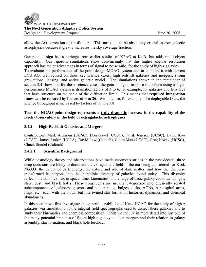
The Next Generation Adaptive Optics System Design and Development Proposal June 20, 2006
-62-
allow the AO correction of tip-tilt stars. This turns out to be absolutely crucial to extragalactic astrophysics because it greatly increases the sky coverage fraction. Our point design has a heritage from earlier studies of KPAO at Keck, but adds multi-object capability. Our rigorous simulations show convincingly that this higher angular resolution approach has major advantages in terms of signal to noise ratio, for the study of high-z galaxies. To evaluate the performance of the point-design MOAO system and to compare it with current LGS AO, we focused on three key science cases: high redshift galaxies and mergers, strong gravitational lensing, and active galactic nuclei. The simulations shown in the remainder of section 3.4 show that for these science cases, the gain in signal to noise ratio from using a high-performance MOAO system is dramatic: factors of 3 to 6, for example, for galaxies and lens arcs that have structure on the scale of the diffraction limit. This means that required integration times can be reduced by factors of 9 to 36. With the use, for example, of 6 deployable IFUs, the science throughput is increased by factors of 50 to 200! Thus the NGAO point design represents a truly dramatic increase in the capability of the Keck Observatory in the field of extragalactic astrophysics. 3.4.2 High-Redshift Galaxies and Mergers
Contributors: Mark Ammons (UCSC), Don Gavel (UCSC), Patrik Jonsson (UCSC), David Koo (UCSC), James Larkin (UCLA), David Law (Caltech), Claire Max (UCSC), Greg Novak (UCSC), Chuck Steidel (Caltech)
3.4.2.1 Scientific Background
While cosmology theory and observations have made enormous strides in the past decade, three deep questions are likely to dominate the extragalactic field in the era being considered for Keck NGAO: the nature of dark energy, the nature and role of dark matter, and how the Universe transformed its baryons into the incredible diversity of galaxies found today. This diversity reflects the complex mix in space, time, kinematics, and energy of basic galaxy constituents: gas, stars, dust, and black holes. These consituents are usually categorized into physically related subcomponents of galaxies: gaseous and stellar halos, bulges, disks, AGNs, bars, spiral arms, rings, etc., each with their own but intertwined star formation histories, dynamics, and chemical abundances.
In this section we first investigate the general capabilities of Keck NGAO for the study of high-z galaxies, via simulations of the integral field spectrographs used to dissect these galaxies and to study their kinematics and chemical composition. Then we inquire in more detail into just one of the many potential branches of future high-z galaxy studies: mergers and their relation to galaxy assembly, star formation, and black hole feedback.

The Next Generation Adaptive Optics System Design and Development Proposal June 20, 2006
-63-
The study of high-redshift galaxies is a powerful driver for multiplexed observations, for example via deployable integral field spectrographs. Areal densities of one to over ten per square arc min on the sky are found, depending on selection criteria of viable targets. How Much Multiplexing is Needed?
One first question to address is how large a field of regard, and how many separate integral field units, are needed in order to accumulate reasonable statistics. Table 6 shows the density on the sky of several galaxy categories, ranging from specific to general.
Table 6 Space Densities of Various Categories of Extragalactic Targets.
Type of Object Approx density per square arc minute Reference
SCUBA sub-mm galaxies to 8 mJy 0.1 Scott et al. 2002
Old and red galaxies with 0.85 < z < 2.5 and R < 24.5 2 Yamada et al. 2005; van
Dokkum et al. 2006 Mergers with emission lines in JHK windows & R < 24 2-5 Conselice et al. 2003
Field galaxies w/ emission lines in JHK windows 0.8 < z < 2.2 & R < 25
> 10 Steidel et al 2004; Coil et al 2004
Center of distant rich cluster of galaxies at z > 0.8 > 20 van Dokkum et al 2000
All galaxies K < 23 > 40 Minowa et al 2005 It is these areal densities which drive the desired field of view and multiplexing for the integral field spectrographs that will accompany Keck NGAO. Our preferred solution for extragalactic astrophysics is a “multi-object” AO system (MOAO) in which there are a modest number of deployable IFU arms, each having its own MEMS-based AO system. Our current notional goal is a field of view of around 2 arc min diameter, with a circular area of ~3 square arc min. While surveys that encompass all galaxies whose strong restframe optical emission lines are redshifted into the near-infrared J, H, or K windows and with R < 25 would require a shockingly high 30 or more separate deployable IFU’s within 3 square arc min, one can see from Table 1 that projects directed at specific subclasses of galaxies can benefit from a half-dozen deployable IFUs within 3 square arc min. Our nominal goal for the NGAO point design is a half dozen deployable IFUs within a 2 arc min diameter field of view, and this would yield sufficient multiplexing to make survey work practical. High sky coverage is facilitated through the use of AO-corrected tip-tilt stars.

The Next Generation Adaptive Optics System Design and Development Proposal June 20, 2006
-64-
What Sky Coverage Fraction can we Expect?
The forefront of extragalactic research today depends heavily on especially well-observed “deep fields” that have been imaged by Hubble, Chandra, XMM, Spitzer, GALEX, and many ground-based telescopes (e.g. the Hubble Deep Fields North and South, the GOODS fields North and South, the Extended Groth Strip, the COSMOS field). Because of the large investment in spacecraft time for these deep fields, they will remain key areas of the sky for extragalactic research for at least the next decade, and quite likely longer. Many of these fields were selected precisely because of their lack of stars. But even tomographic LGS AO needs faint natural guide stars (for tip, tilt, and focus correction). To check whether enough sufficiently-bright stars exist within these fields to ensure utility of Keck NGAO, we used the exact configuration of stars in GOODS North and South and in part of COSMOS to calculate the blurring of the central diffraction-limited core of the AO PSF, due to lack of a perfect tip-tilt correction. Law et al. (2006) showed that the best signal to noise ratio for integral field spectroscopy of high-z galaxies was achieved using IFU spaxels (e.g. lenslets or slitlets) of diameter 0.1 arc sec (100 mas). Table 2 shows the fraction of the sky in these fields for which galaxy light would be inserted efficienty into spaxels of dimension 100 mas, 50 mas, and 20 mas. Specifically the table entries refer to the sky fraction over which the tip-tilt blurring is < 1/3 of the spaxel size. The fractions are high, because the NGAO system will use AO-corrected tip-tilt stars.
Table 7 Fractional sky coverage into IFU spaxels of three different sizes for four "deep fields," assuming that the galaxy contains point-like substructure.
Deep Field
Sky fraction into 100 mas spaxel
Sky fraction into 50 mas spaxel
Sky fraction into 20 mas spaxel
GOODS N 65% 25% 5%
GOODS S 90% 40% 20%
COSMOS/EGS 100% 100% 70%
Clearly the most challenging field is GOODS-N. But even for this field the fraction of the sky over which tip-tilt blurring is less than 33 mas is 65%. This is because most of the light from a point-like source can be fit into a 100 mas spaxel even in cases when the tip-tilt blurring is noticeably larger than the size of the diffraction limited core of the PSF.

The Next Generation Adaptive Optics System Design and Development Proposal June 20, 2006
-65-
Figure 26 Map of tip-tilt blurring, in mas, in the GOODS-North, GOODS-South, and part of the COSMOS
deep fields. A respectable fraction of these three deep fields is accessible to tomographic observations with NGAO, with less than
25 mas of tip-tilt blurring. GOODS North poses the greatest challenge, but even here more than 20% of the area produces acceptable tip-tilt errors. For further details of these calculations see 4.3.2.2.3.
We have performed computer simulations to evaluate the potential improvements provided by Keck NGAO, compared with the current Keck II LGS AO system, focusing on galaxies at z > 0.6. We assumed that each integral field spectrograph was similar in performance to OSIRIS, but with the improved background levels described in Section 4.3.2.1. Results are shown in Figure 27.

The Next Generation Adaptive Optics System Design and Development Proposal June 20, 2006
-66-
Figure 27 Signal to noise ratio for an OSIRIS-like IFU with NGAO.
NGAO (upper curve), compared with today’s OSIRIS with LGS AO (bottom curve). Over the redshift range 0.6 – 2.3, NGAO shows a factor of 3 to 6 times improvement in signal to noise ratio. Here we have assumed lenslet sizes of 0.1
arcsec, and the improved thermal backgrounds described in Section 4.3.2.1. NGAO will yield a signal to noise ratio 3 - 6 times higher than the current Keck LGS AO system, for the same exposure times. For background-limited measurements this would yield an exposure-time reduction of a factor of 9 to 36. Adding multiple IFUs in the system will multiply the efficiency yet again. Thus our nominal 6 IFU MOAO system will yield a dramatic total gain of a factor of 50 to 200 in the completion rate for survey-level programs, relative to the current LGS AO OSIRIS system. This is an astounding advance in the potential of AO systems to finish deep spectroscopic surveys of the distant universe! Figure 28 shows a simulation of integral field unit imaging and spectroscopy for the current LGS AO system and for the proposed NGAO system. The galaxy being observed is BX 1332 from Law et al. (2006). It is a z ~ 2 star-forming galaxy from the catalog of Erb et al. (2004). In Figure 28 one can clearly see the advantage of improved signal to noise ratio: one can image a larger fraction of the galaxy so as to study its morphology, and one can recover a velocity curve over a region of the galaxy that is more than twice as large. These results are very strong motivations for the development of deployable integral field spectroscopy working with the NGAO system.

The Next Generation Adaptive Optics System Design and Development Proposal June 20, 2006
-67-
Figure 28 Computer simulation of imaging and spectroscopy of the z ~ 2 galaxy BX 1332 from the catalog of
Erb et al. (2004). The planned NGAO system shows a 3x improvement in signal to noise ratio for the same exposure time, enabling the study of galaxy morphology for large surveys in practical amounts of telescope time. The NGAO system also allows
extraction of a velocity map over about 3x more area within the galaxy than the current LGS AO system. For the velocity maps, only those pixels within 3σ of the mean SNR are shown. We have assumed a lenslet size of 0.1 arc sec. 3.4.2.2 Showcase Study: Mergers of High Redshift Galaxies
To evaluate the scientific benefits of the higher SNR of NGAO, here we focus on one particular science example: mergers of high-z galaxies. Within the suite of physical processes that govern the formation of galaxies and their subcomponents, hierarchical merging remains a fundamental paradigm within the ΛCDM model, the leading cosmology to explain the assemblage of galaxies, groups, and clusters. Mergers and galaxy interactions are believed to play a key role 1) in the formation of luminous infrared galaxies; 2) in the balance of early to late type galaxies through the formation of ellipticals/ spheroids/ bulges and the destruction or thickening of disks; 3) in the the triggering of AGNs and feeding of their supermassive black holes; and 4) in the initiation of high energy output via starbursts and AGNs that results in blowing gas into the intergalactic medium, heating of surrounding gas within the galaxy, and perhaps quenching of future star formation.
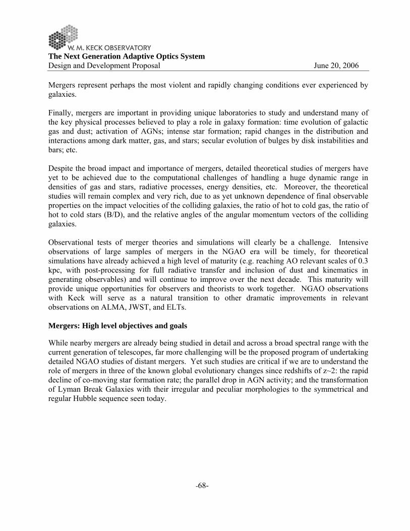
The Next Generation Adaptive Optics System Design and Development Proposal June 20, 2006
-68-
Mergers represent perhaps the most violent and rapidly changing conditions ever experienced by galaxies. Finally, mergers are important in providing unique laboratories to study and understand many of the key physical processes believed to play a role in galaxy formation: time evolution of galactic gas and dust; activation of AGNs; intense star formation; rapid changes in the distribution and interactions among dark matter, gas, and stars; secular evolution of bulges by disk instabilities and bars; etc. Despite the broad impact and importance of mergers, detailed theoretical studies of mergers have yet to be achieved due to the computational challenges of handling a huge dynamic range in densities of gas and stars, radiative processes, energy densities, etc. Moreover, the theoretical studies will remain complex and very rich, due to as yet unknown dependence of final observable properties on the impact velocities of the colliding galaxies, the ratio of hot to cold gas, the ratio of hot to cold stars (B/D), and the relative angles of the angular momentum vectors of the colliding galaxies. Observational tests of merger theories and simulations will clearly be a challenge. Intensive observations of large samples of mergers in the NGAO era will be timely, for theoretical simulations have already achieved a high level of maturity (e.g. reaching AO relevant scales of 0.3 kpc, with post-processing for full radiative transfer and inclusion of dust and kinematics in generating observables) and will continue to improve over the next decade. This maturity will provide unique opportunities for observers and theorists to work together. NGAO observations with Keck will serve as a natural transition to other dramatic improvements in relevant observations on ALMA, JWST, and ELTs. Mergers: High level objectives and goals
While nearby mergers are already being studied in detail and across a broad spectral range with the current generation of telescopes, far more challenging will be the proposed program of undertaking detailed NGAO studies of distant mergers. Yet such studies are critical if we are to understand the role of mergers in three of the known global evolutionary changes since redshifts of z~2: the rapid decline of co-moving star formation rate; the parallel drop in AGN activity; and the transformation of Lyman Break Galaxies with their irregular and peculiar morphologies to the symmetrical and regular Hubble sequence seen today.
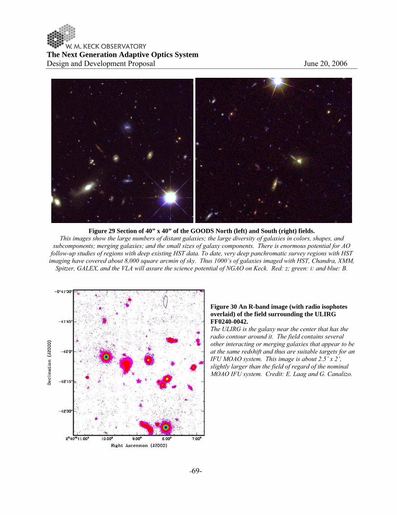
The Next Generation Adaptive Optics System Design and Development Proposal June 20, 2006
-69-
Figure 29 Section of 40” x 40” of the GOODS North (left) and South (right) fields.
This images show the large numbers of distant galaxies; the large diversity of galaxies in colors, shapes, and subcomponents; merging galaxies; and the small sizes of galaxy components. There is enormous potential for AO
follow-up studies of regions with deep existing HST data. To date, very deep panchromatic survey regions with HST imaging have covered about 8,000 square arcmin of sky. Thus 1000’s of galaxies imaged with HST, Chandra, XMM,
Spitzer, GALEX, and the VLA will assure the science potential of NGAO on Keck. Red: z; green: i: and blue: B.
Figure 30 An R-band image (with radio isophotes overlaid) of the field surrounding the ULIRG FF0240-0042. The ULIRG is the galaxy near the center that has the radio contour around it. The field contains several other interacting or merging galaxies that appear to be at the same redshift and thus are suitable targets for an IFU MOAO system. This image is about 2.5’ x 2’, slightly larger than the field of regard of the nominal MOAO IFU system. Credit: E. Laag and G. Canalizo.

The Next Generation Adaptive Optics System Design and Development Proposal June 20, 2006
-70-
3.4.2.3 How does NGAO help?
AO with the 10 m Keck provides a spatial resolution in the near infrared (1.2 μm to 2.3 μm) that is a nearly ideal in a match to that of HST in the ultraviolet and visible. This will allow us to study galaxy subcomponents on the scale of ~ 0.4 to 1 kpc at redshifts z > 0.5 (angular scales 0.05 to 0.1 arcsec). While HST with its 2.4 m diameter mirror can probe to these resolutions in the optical, at high redshifts the observed optical is viewing the restframe ultraviolet, while Keck AO in the near infrared is observing the restframe optical to near-infrared. Such high resolution near infrared imaging provides a better probe of older stellar populations, adds complementary data to HST images by widening the spectral range to study stellar populations at the same spatial resolution, and is far less affected by dust extinction. Moreover, spectroscopy in the near infrared provides access to strong and highly probative emission lines of Hα, [NII], [OIII], Hβ, and [OII] for highly redshifted galaxies. These lines at high spatial and spectral resolutions provide direct and powerful measures of star formation rates; AGN activity; gas ionization, density, shocks, and metallicity; dust extinction; and kinematics that yield dynamical masses, gas outflows, and direct signatures of the strength of mergers and interactions. We have used results from merger simulations by Patrik Jonsson, T. J. Cox, Greg Novak, and Joel Primack (Jonsson et al. 2006) to feed IFU simulations by David Law (Law et al. 2006) to compare the relative capabilities of Keck NGAO and present LGS AO in the study of high-z mergers. The merger simulations include dust extinction, radiative transfer, star formation, and metallicity, and assume an AGN-free merger. Figure 31 shows simulated IFU-derived images and velocity fields for a merger in progress. With NGAO, images similar to the kinematic maps above will be derived for star formation rates, metallicity distributions, velocity dispersion, and age.

The Next Generation Adaptive Optics System Design and Development Proposal June 20, 2006
-71-
Figure 31: Improvements in SNR and velocity measurements with NGAO. Top: Signal to noise ratio for Hα emission line from simulated major merger at z = 2.2, midway through the merger
process observed with current LGSAO system (left) and with the proposed Keck NGAO system (right). There are only a few pixels with SNR ≥ 10 (yellow) using current LGSAO, but there are an order of magnitude more such pixels with NGAO! Lower two panels: Kinematic maps for the same cases as the upper panels, showing velocities measured for
pixels with SNR > 5. Note the difficulty of determining with current LGS AO whether the lower left panel is kinematically differentiated from a typical ordered rotation velocity map with smooth transition across the galaxy from red (positive velocities) to violet (negative velocities). The NGAO panel clearly displays a spatially complex
distribution of red to violet colors, which characterizes a major merger. The higher sensitivity and speed of NGAO together with the multiplexing advantage of multiple IFUs will allow a total gain of 50 - 200 in throughput. This is essential for the study of distant mergers where the complexity of the issues requires samples of many 100’s of targets, the faintness of the targets requires long exposures, and the relatively low surface density of the best targets (see Figure 30) benefits from the multiplexing that is provided by MOAO. Also of high importance in taking advantage of existing very deep complementary data from HST, Spitzer, Chandra, and eventually JWST and ALMA, will be access to the maximum sky coverage through NGAO use of AO corrected tip-tilt stars, since only a few very special regions of the sky (GOODS, EGS, GEMS, COSMOS) are likely to have the full suite of multiwavelength data for the foreseeable future.
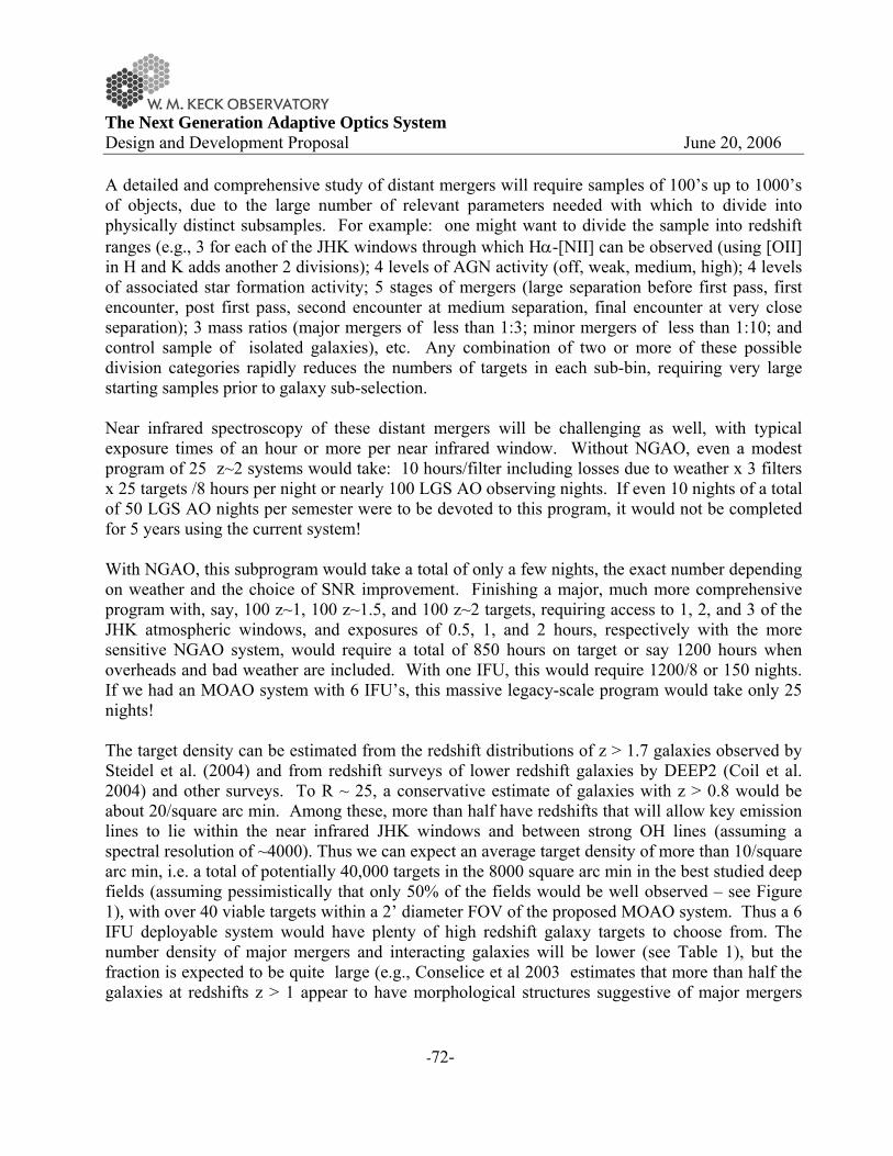
The Next Generation Adaptive Optics System Design and Development Proposal June 20, 2006
-72-
A detailed and comprehensive study of distant mergers will require samples of 100’s up to 1000’s of objects, due to the large number of relevant parameters needed with which to divide into physically distinct subsamples. For example: one might want to divide the sample into redshift ranges (e.g., 3 for each of the JHK windows through which Hα-[NII] can be observed (using [OII] in H and K adds another 2 divisions); 4 levels of AGN activity (off, weak, medium, high); 4 levels of associated star formation activity; 5 stages of mergers (large separation before first pass, first encounter, post first pass, second encounter at medium separation, final encounter at very close separation); 3 mass ratios (major mergers of less than 1:3; minor mergers of less than 1:10; and control sample of isolated galaxies), etc. Any combination of two or more of these possible division categories rapidly reduces the numbers of targets in each sub-bin, requiring very large starting samples prior to galaxy sub-selection. Near infrared spectroscopy of these distant mergers will be challenging as well, with typical exposure times of an hour or more per near infrared window. Without NGAO, even a modest program of 25 z~2 systems would take: 10 hours/filter including losses due to weather x 3 filters x 25 targets /8 hours per night or nearly 100 LGS AO observing nights. If even 10 nights of a total of 50 LGS AO nights per semester were to be devoted to this program, it would not be completed for 5 years using the current system! With NGAO, this subprogram would take a total of only a few nights, the exact number depending on weather and the choice of SNR improvement. Finishing a major, much more comprehensive program with, say, 100 z~1, 100 z~1.5, and 100 z~2 targets, requiring access to 1, 2, and 3 of the JHK atmospheric windows, and exposures of 0.5, 1, and 2 hours, respectively with the more sensitive NGAO system, would require a total of 850 hours on target or say 1200 hours when overheads and bad weather are included. With one IFU, this would require 1200/8 or 150 nights. If we had an MOAO system with 6 IFU’s, this massive legacy-scale program would take only 25 nights! The target density can be estimated from the redshift distributions of z > 1.7 galaxies observed by Steidel et al. (2004) and from redshift surveys of lower redshift galaxies by DEEP2 (Coil et al. 2004) and other surveys. To R ~ 25, a conservative estimate of galaxies with z > 0.8 would be about 20/square arc min. Among these, more than half have redshifts that will allow key emission lines to lie within the near infrared JHK windows and between strong OH lines (assuming a spectral resolution of ~4000). Thus we can expect an average target density of more than 10/square arc min, i.e. a total of potentially 40,000 targets in the 8000 square arc min in the best studied deep fields (assuming pessimistically that only 50% of the fields would be well observed – see Figure 1), with over 40 viable targets within a 2’ diameter FOV of the proposed MOAO system. Thus a 6 IFU deployable system would have plenty of high redshift galaxy targets to choose from. The number density of major mergers and interacting galaxies will be lower (see Table 1), but the fraction is expected to be quite large (e.g., Conselice et al 2003 estimates that more than half the galaxies at redshifts z > 1 appear to have morphological structures suggestive of major mergers

The Next Generation Adaptive Optics System Design and Development Proposal June 20, 2006
-73-
and strong interactions.) The main point is that the special deep-field regions of sky already have plenty of targets to take full advantage of a 6 (or greater number) IFU MOAO system! 3.4.2.4 How do ground-based optical-infrared observations complement space-based
observations and information from other wavelengths?
The diffraction limited spatial resolution with the Keck 10 m telescope in the near infrared is almost identical to that achieved by HST in the optical, so the complementarity is ideal in probing to the same spatial scales and thus same galaxy subcomponents. Keck observations provide photometry, allowing wider spectral range for dust, AGN, and stellar population studies, and spectroscopy, allowing improved diagnostics for star formation rates, metallicity, ionization, AGN, and kinematics. This complementarity applies to almost any sample of high redshift galaxies. Even once JWST is operating with its 6-m mirror, the Keck resolution will be superior. While the JWST project is still alive after the most recent NASA funding cuts, its schedule and viability are by no means assured, given the high risk for schedule delay, damage, or unsuccessful launch in any space mission. If JWST does not become a reality (or until JWST becomes a reality), any period after HST is no longer in operation will be one in which ground-based telescopes with AO will provide almost the only high spatial resolution imaging and spectroscopy. ALMA is expected to reach some level of scientific operation by the era of NGAO. With spatial resolutions of 0.01 to 0.1 arcsec, ALMA will provide complementary data on molecular gas and dust content, spatial distributions, and kinematics to the gas emission line information from the proposed Keck NGAO program. Such molecular clouds will likely be included in the more advanced theoretical simulations of galaxy interactions, and thus will provide additional constraints on our understanding of mergers and their associated physical processes. 3.4.2.5 AO and instrument requirements
Program description:
Specific observables: IFU 2-D spectra within J, H, and K band windows
Sample targets: Mergers at different stages, with different galaxy properties, and at different redshifts (z ~ 1, 1.5, 2.1) within fields that already have had enormous investment from HST, Spitzer, Chandra.
Density on sky: 1 to 10 per square arc minute
Spatial resolution: 0.05 to 0.1 arc sec (for IFU the best signal to noise performance is for 0.1 arc sec lenslets or slits)
Exposure time per target: 0.5 to 10 hours
Fainter tip-tilt stars will improve sky coverage, which is especially important to get maximal data from hard-wired regions like GOODS, GEMS, COSMOS, and EGS.

The Next Generation Adaptive Optics System Design and Development Proposal June 20, 2006
-74-
Total number of nights needed to complete observing program Depending on number of MOAO IFU units, but a 6 MOAO IFU system would allow completion of a comprehensive merger program of 300 targets as described above in about 25 nights. Essential: 0.1 arc sec sampling with an IFU over 2”x2” patch of sky. Field of view for MOAO of 2 arcmin diameter. ADC so we can reach high airmass. Spectral resolution >3500 to “see” in between the OH lines. Thermally cooled AO so that K band is accessible at lower noise levels than current OSIRIS. Strehl > 20% in J under median seeing conditions. 5%-10% photometric precision Absolute minimum of 3 IFU’s and ability to add more, perhaps up to 20. Each IFU is the equivalent of having another Keck telescope so the throughput gains are very high. Desirable, but not absolutely essential: More IFUs – 10 is a good number; 20 is an upper limit given density of targets and total accessible targets. Option for 0.05 arc sec sampling over >4” of sky for the IFU (mergers are more extended than typical galaxies). Background limited work at spectral resolution of 5,000, 10,000 (velocity dispersions to 30 km/s), 20,000 (line profile shapes for winds). Strehl > 30% in J under median seeing conditions. Still need to investigate what could be achieved with brand new instruments (e.g. super-NIRC2, super-OSIRIS, visible imager, visible IFU, more numerous near-IR deployable IFUs). 3.4.2.6 References
Coil et al. 2004, ApJ, 617, 765 Conselice et al 2003, AJ, 126, 1183 Erb et al. 2004, ApJ, 612, 122 Jonsson et al. 2006, ApJ, 637, 255 Law, Steidel, and Erb 2006, AJ, 131, 70 Minowa et al. 2005, ApJ, 629, 29 Scott et al. 2002, MNRAS, 331, 817 Steidel et al . 2004 ApJ, 604, 534 van Dokkum et al. 2000, ApJ, 541, 95 van Dokkum et al. 2006 , ApJL, 638, 59 Yamada et al. 2005, ApJ, 634, 861

The Next Generation Adaptive Optics System Design and Development Proposal June 20, 2006
-75-
3.4.3 Strong Gravitational Lensing
Authors: Tommaso Treu (UCSB), Laura D. Melling (UCSB)
3.4.3.1 Scientific Background
3.4.3.1.1 Introduction
Massive clusters and galaxies produce a local perturbation of the Robertson-Walker metric that distorts our view of background objects. Gravitational lensing is achromatic and preserves surface brightness. Under appropriate circumstances, if the deflector is dense enough and the impact parameter is small enough, multiple images of the background source appear to the observer. This regime is called strong gravitational lensing. Strong gravitational lensing is extremely useful for the study of the high redshift universe for two main reasons: i) the astrometry of the lens configuration depends on the mass distribution of the deflector and on angular size distances, and thus can be used to “weigh” galaxies/clusters, determine the structure and substructure of dark matter halos, and/or to measure cosmography; ii) the background source is highly magnified both in terms of apparent size and apparent luminosity, so that lenses act as natural gravitational telescopes; magnification is quite significant, typically in the range of 10 to 25 in luminosity. Precision astrometry is the name of the game for gravitational lensing. So far the Hubble Space Telescope has been the unchallenged leader in this field. Laser guide star adaptive optics has the potential to change the field. The large mirror-size of Keck can deliver a factor of four improvement in angular resolution over HST if high Strehl ratios can be achieved with NGAO. Furthermore, coupling an AO system with integral field spectrographs will open the way for high spatial resolution studies of dynamics and chemistry of galaxies in the distant universe and for detection and spectroscopy of the first galaxies and sources of reionization at a redshift z > 7-8. As illustrated by the simulations shown below, Keck with NGAO is better than HST for these purposes and will dominate the subject after the demise of HST.
3.4.3.1.2 Galaxy versus Cluster Lensing
It is useful to separate two regimes: cluster/group lensing and galaxy size lensing. The angular size is set by the Einstein radius, which in turn scales as the velocity dispersion squared. Hence typical galaxies will have Einstein radii of order 1”, while massive clusters in the same redshift configuration will have Einstein radii of order 30” (Figure 32). Furthermore, clusters – with their longer caustics – have much higher chances than galaxies to lens multiple background objects and in general to be strong lenses. So clusters are rarer in the sky but they are very efficient lenses. Galaxies are more common in the sky, but they are much more unlikely to be lenses. From a practical point of view, galaxy and cluster scale lenses require different strategies for detection and scientific exploitation, and have different instrumental requirements. Galaxy scale lenses have the more stringent requirements in terms of spatial resolution and Strehl ratios, while cluster scale lenses are more demanding in terms of field of

The Next Generation Adaptive Optics System Design and Development Proposal June 20, 2006
-76-
view. Therefore they will be treated separately in this document. The intermediate regime, group size lensing, is a very poorly known subject. In general NGAO will be useful for group size lensing as well, but with intermediate requirements between galaxy and cluster scale lensing for spatial resolution and field of view. Therefore we do not discuss group size lensing in this document.
Figure 32 Typical angular scales of cluster-size lensing and galaxy-size lensing. The curves show the size of Einstein radius for a massive cluster (velocity dispersion 1250 km/s) and a massive
elliptical (300 km/s) as a function of deflector redshift. A field of view of 3-4” is well matched to galaxy-size lensing, while a field of 1-2’ is well matched to cluster-scale lensing.
3.4.3.2 Galaxy-Scale Lensing
The main science goals for this subfield are:
o Mass distribution of (deflector) galaxies, mostly early-type galaxies. What is the mass profile of dark matter halos? What is the fraction of dark matter as a function of galaxy radius, redshift, mass? Do galaxy-size halos have dark matter substructure as predicted by cosmological numerical simulations?
o Morphology, resolved kinematics and star formation history/chemistry of faint spiral irregular galaxies. Galaxies can be super-resolved by exploiting lensing magnification. Using NGAO + lensing, the effective diffraction limit in the source plane will typically

The Next Generation Adaptive Optics System Design and Development Proposal June 20, 2006
-77-
be ~0.005”. This means that galaxies at z=2 (angular distance 1.7Gpc) can be studied with the same detail as a galaxy in the Virgo cluster (17Mpc) in 0.5” seeing.
o Cosmography through time-delays. If relative photometric precision of order a few percent can be achieved across the field, monitoring of variable lensed sources (such as AGN) can be used to determine cosmological parameters. Effectively, every time delay acts as a standard rod. For every system angular size distances can be obtained with 10-15% and therefore there are real prospects of determining the Hubble Constant to 5% precision if a sample of a few dozen time-delays can be obtained. NGAO would be exceptionally good at this since one needs to do photometry of sources separated by less than 1 arc sec.
Galaxy-size lenses are rare on the sky, their density is of order 10 per square degree (depending on depth and resolution). NGAO will not be a good instrument to search for lenses but by the time NGAO will be available hundreds of lenses will have been discovered with current technology (e.g. SLACS, Haggles, CFHT Legacy Survey). Thousands of lenses are expected to be discovered by ongoing and future spectroscopic and imaging surveys, such as DEEP2, z-Cosmos, Panstarrs and LSST. The scientific exploitation of these samples of lenses will require high resolution imaging that only NGAO can provide. Analyzing a large number of objects is vital for the applications listed above. For example, in order to detect substructure, satellites must be close to the critical lines, which will happen only in a small fraction of cases. To beat down small number statistics samples of hundreds of lenses are needed. 3.4.3.3 Cluster-Scale Lensing
The main science goals for this sub-field are:
o Mass distribution of clusters. Do cluster halos resemble those in numerical simulations in terms of mass profiles, substructure, shape etc? What is the accuracy of X-ray mass estimates for cosmography?
o Clusters as gravitational telescopes. Can we identify the first galaxies/quasars? What is their luminosity function to the faint limits? What are the sources of reionization? With typical magnifications of order 20, searches for zJH dropouts can be extended three magnitudes deeper than possible without gravitational telescopes.

The Next Generation Adaptive Optics System Design and Development Proposal June 20, 2006
-78-
Figure 33 Searching for multiple images. At HST-like depth and resolution there are many multiple images of background sources for each massive cluster; The case of Abell 1689, an enormous cluster with an Einstein radius of 50'' is shown (the image is approximately 3’ on a
side); 106 multiple images have been detected in this case (Broadhurst et al. 2005). Most clusters show strong lensing when imaged deep enough at high resolution. For example, in relatively shallow HST images (~1 orbit WFPC), Sand et al. (2005) found 104 giant arcs in 128 clusters. NGAO system will have a similar performance, and thus a success rate close to 100% can be assumed, with a density of multiply imaged sources of a few per square arcminute. In extreme cases a density of 10 per square arcminutes can be achieved (see Abell 1689 in Figure 33). As for galaxy size lenses, NGAO will not be competitive for finding cluster lenses, so the main mode of operation would be follow-up of known clusters. Current and future surveys (X-ray, red sequence) will find thousands of high redshift clusters. Targets will be abundant, high resolution follow-up will be the domain of NGAO. 3.4.3.4 Proposed Observations and Targets
For simplicity we will consider the ideal case of an early-type galaxy at z = 0.8 lensing a galaxy at z = 7. The deflector is a typical L* early-type galaxy with velocity dispersion 250 km/s, K = 18. The source is chosen to represent a candidate source of reionization: a young galaxy of ~100Myr age, a few billion solar masses of stellar mass, with small size (0.05” effective radius), similar to the one identified by Kneib et al. (2004) behind the galaxy cluster Abell 2218. The unlensed AB

The Next Generation Adaptive Optics System Design and Development Proposal June 20, 2006
-79-
magnitude of the source are F814W=28.6, F850LP=26.3, J/F110W=25, H/F160W=24.2, K/F222M=24.4. This case illustrates simultaneously the strength of NGAO for mass modeling of lens galaxies/clusters and for studying faint magnified galaxies. The quantitative results found for this case can be extrapolated to other observing programs such as a survey for z-band dropouts. 3.4.3.5 Comparison of NGAO with Current LGS AO and with HST-NICMOS
Figure 3 shows the lens system as observed with NICMOS (top row), NGAO with an upgraded version of NIRC2 (middle row), and the current Keck II LGS AO system with NIRC2 (bottom row). We simulate observations in the J, H and K band. For NICMOS in the J and H band (F110W and F160W) we used the NIC-1 camera because the pixel scale is very similar to that of NIRC2 (0.043” vs. 0.04”). In K band the closest configuration we could find for HST was NIC2 with the F222M filter. We show the results of this simulation even though it is not competitive, because Hubble has a high thermal background and was not optimized for observations in K band. For NGAO we used PSFs from simulations by Donald Gavel. We assumed the science instrument was an upgraded version of NIRC2 with half the background currently measured, assuming that this can be improved in the next generation AO system. For LGS AO, we assumed natural seeing of 0.5” and Strehl ratios of 0.15, 0.2 and 0.3 respectively for J, H, and K. The exposure time is 3600s in all cases. Each image is 4” on a side. Details of the simulations are given at the end of this Gravitational Lensing subsection. From Figure 34 it is apparent that NGAO performs markedly better than both NICMOS and the current LGS AO system. At J and H bands NICMOS performs better than the current LGS AO system (largely due to lower background), whereas at K band LGS AO performs better than NICMOS. For NGAO the gain in resolution and collecting area more than offsets the extra background seen by NGAO with respect to NICMOS.

The Next Generation Adaptive Optics System Design and Development Proposal June 20, 2006
-80-
Figure 34 Simulated observations of a gravitational lens. The simulations are for NGAO (middle row), HST-NICMOS (top row) and the current LGSAO system (bottom row). Each image is 4" on a side and the exposure time is 3600s. For NGAO we adopted the same detector properties as
NIRC2 and half the background. The lens is an L* elliptical at z=0.8 and 250km/s velocity dispersion. The background source is a galaxy at z=7 with 0.05" half light radius, and J H K AB magnitudes of 25, 24.2,
24.4, as obtained for a few billion solar masses of a young stellar population (see text for details). Note that NGAO is superior in all cases.
Quantitative estimates of the uncertainties on the source parameters are shown in Figure 4 (68% and 95% contours). Those are obtained by measuring the likelihood in the full multidimensional space of lens and source parameters using a Markov Chain Monte Carlo sampler (Melling & Treu 2006, in prep). The signal to noise ratio of the NIC2-F222M image was too faint to derive any useful constraints on the source properties. Similarly the signal to noise ratio of the Keck LGS AO-J band image was sufficiently low that the method failed to converge at the right minimum. As is apparent from Figure 35, the proposed NGAO system strongly reduces the uncertainty in measurements of lensed galaxy size and mass. For example the derived uncertainty in size of the lensed galaxy at H band was a factor of four smaller with NGAO than with current LGS AO, and more than a factor of two smaller with NGAO than with NICMOS.

The Next Generation Adaptive Optics System Design and Development Proposal June 20, 2006
-81-
Figure 35 Reconstructed 68% and 95% confidence contours for the source parameters, from a Markov Chain Monte Carlo algorithm.
The contours for NGAO are a factor of six smaller than for LGSAO and half the size of those for NICMOS. Note also that the half radius of 0.05 arcsec is clearly resolved and precisely measured. The SNR of the simulated data is too
low for LGSAO-J and NIC2-F222M to obtain meaningful results.
Likewise the uncertainty on the velocity dispersion decreases by a factor of 6 going from LGS AO to NGAO, and by a factor of 2 going from NICMOS to NGAO in J and H bands. Formal statistical uncertainties of better than 0.1% on the velocity dispersion can be achieved with NGAO; this is a stunning achievement for any AO system.

The Next Generation Adaptive Optics System Design and Development Proposal June 20, 2006
-82-
Summarizing these results, for typical galaxy lensing cases the proposed NGAO system is expected to perform four to six times better than the current LGS AO system in its ability to correctly recover the key properties of the lensed galaxies.
3.4.3.6 Sample Observational Programs
The luminosity and size distribution of redshift 7-8 galaxies, using gravitational telescopes. Assuming that high Strehl ratio images can be obtained in the z band, NGAO would be extremely efficient for doing a survey of massive clusters at zJHK and for measuring the size and luminosity function of redshift 7-8 galaxies. The luminosity function of z>7 galaxies is currently very poorly known. Bouwens et al. (2004) found 5 z-band dropout candidates in the NICMOS follow-up of the Hubble Ultra Deep Field finding (5.76 square arc min), with F160W luminosity ~27 AB. Pello et al. (2005) surveyed the high magnification regions of two lensing clusters with ISAAC on the VLT, to a depth of H=26 AB, finding several promising photometric candidates in an area of approximately 8 square arc min. The brightest sources are estimated to have stellar masses of order of a few times 108 solar masses. Kneib et al. 2004 report one z~7 candidate that is very similar to the one adopted for our simulations, in terms of apparent magnitudes in the image plane. As shown above, if similar Strehl ratios can be achieved over a 2’ field, it will be possible to image the highly magnified regions of clusters to comparable depths in just 1 hour per band. This makes it feasible to survey dozens of clusters to this depth and achieve an order of magnitude improvement in area in just a few nights of telescope time. Kinematics of faint galaxies. With an integral field unit behind an NGAO system one can obtain spatially resolved kinematics of galaxies at z up to 2.2 (with Hα in the K band). See Moller & Noordermeer (2006) and Law, Steidel & Erb (2006) for more details. 3.4.3.7 AO and instrument requirements (needs to be completed)
Galaxy-lensing. AO requirements:
Crucial: high Strehl at H and K (>0.5), field of view of at least 2”, possibly up to 4”.
Desirable: high Strehl (>0.5) at J and in the optical, to extend range of redshifts and diagnostics. Spectroscopic capabilities with R=3000 or better for internal kinematics and spectral diagnostics. PSF stability for relative photometry to a few percent, to allow monitoring of lensed quasars for gravitational time delays.
Cluster-lensing. AO requirements:
Crucial: high Strehl, Y/J band for Y/J dropouts, field of view of 1-2’ on a side for imaging.
Desirable: multiple deployable IFU units for simultaneous spectroscopy of lensed sources. Spectral resolution of 5000 or better is required to take spectra in between the OH lines.

The Next Generation Adaptive Optics System Design and Development Proposal June 20, 2006
-83-
3.4.3.8 References
Bouwens et al. 2004, ApJ, 616, L79
Broadhurst T. et al. 2005, ApJ, 621, 53
Kneib J.-P. et al. 2004, ApJ, 607, 697
Law D., Steidel, C.C & Erb. D 2006, AJ, 131, 70
Moller O. & Noordermeer 2006, MNRAS, 365, 469
Pello R. et al. 2005, preprint, astro-ph/0510180
Sand D.J., Treu T., Ellis R.S., Smith G.P. 2005, ApJ, 627, 32 3.4.4 Active Galactic Nuclei and Black Holes
Contributors: Aaron Barth (UC Irvine), Claire Max (UCSC)
3.4.4.1 Scientific Background
3.4.4.1.1 Introduction
During the past several years it has become increasingly clear that black holes play a key role in galaxy formation and evolution. The most important evidence for a close connection between black hole growth and galaxy evolution comes from the observed correlations between black hole mass and the bulge velocity dispersion of the host galaxy (the “M-σ relation”), and from the correlation between black hole mass and bulge mass. Despite the fact that black holes contain only about 0.1% of the mass of their host bulge, their growth is evidently constrained very tightly by the kiloparsec-scale properties of their environment. In addition, simulations and theory have highlighted the importance of feedback from active galactic nuclei (AGNs), in the form of winds or outflows which can serve to shut off AGN fueling and potentially expel a significant fraction of the host galaxy's gas into the intergalactic medium following a major merger. AGN feedback is frequently invoked as a mechanism to limit black hole growth and to shut off star formation in early-type galaxies, but observational evidence for this scenario remains sketchy. Some key observational goals in this field include:
● Accurate determination of the demographics of black holes in nearby galaxies, over the widest possible range in black hole mass
● Investigations of the redshift evolution of the M-σ relation ● Studies of the host galaxies of AGNs out to high redshifts to determine bulge luminosities,
stellar populations, and emission-line kinematics.
The Next Generation Adaptive Optics System Design and Development Proposal June 20, 2006
-84-
AO observations will be crucial in addressing these issues over the next decade. Currently, with no spectroscopic capability on HST, AO observations are the only way to pursue dynamical measurements of black hole masses, apart from the very few special cases of AGNs hosting water megamaser disks. AO data is already beginning to play an important role in this field and near-IR observations have the important advantage of being able to probe the central regions of dust-obscured galaxies, for example in Centaurus A (Silge et al. 2005). AO observations in the near-IR will be used to search for starlight from quasar host galaxies at high redshifts, but to date results have been severely limited by the quality of AO corrections available with current-generation facilities. Here we discuss just a few possible AGN and black hole projects that will benefit from NGAO at Keck. For the observations described below, the most desirable AO capability will be a high-Strehl AO correction in the near-IR with a highly stable PSF, even if only over a narrow field of view (~15 arcsec). An AO correction operating at wavelengths as short as the Ca II triplet (8500 A) will have important applications for black hole mass measurements as well. 3.4.4.1.2 Black hole masses in nearby galaxies
Detections of the black holes in the Milky Way and in the megamaser galaxy NGC 4258 remain the “gold standard” in this field, but the majority of black hole detections to date have been done with HST, and are limited to galaxies without significant dust obscuration. In the best cases, observations of spatially resolved stellar or gas dynamics can yield black hole masses with uncertainties in the range ~10-20%, which is sufficient for an accurate determination of the M-σ relation. Currently, although there are about 30 detections of massive black holes, the slope and the amount of scatter in the M-σ relation remain somewhat controversial. In particular, the extreme ends of the black hole mass spectrum, above 109 and below 107 solar masses, remain poorly determined. Improvements in angular resolution lead directly to increased accuracy in black hole mass measurements, and NGAO at Keck will be the next significant new capability in this field. In order to detect a black hole with high significance, the observations must resolve the black hole's dynamical sphere of influence-- the region in which the black hole dominates the gravitational potential. As an example, the projected radius of the gravitational sphere of influence for a 108 solar mass black hole in a galaxy with σ = 200 km/sec at D = 20 Mpc is only 0.1 arcsec. Currently, black holes with masses below 107 solar masses can only be detected out to distances of a few Mpc, severely limiting the opportunities to measure the low-mass end of the M-σ relation. At the high-mass end, for black holes above 109 solar masses, there are only a handful of potential targets within reach of current observations. For black hole detection, NGAO offers two important advantages over current capabilities. First, compared with current LGSAO, the improved PSF quality and stability will significantly reduce

The Next Generation Adaptive Optics System Design and Development Proposal June 20, 2006
-85-
the measurement uncertainty in black hole masses, for observations in the near-IR. Second, an AO capability in the I band will open up the possibility of using the Ca II triplet lines, giving a PSF core that is narrower than in the near-IR, which will extend the distance out to which the most massive black holes can be detected. The minimum black hole mass detectable with a given angular resolution can be roughly estimated under the assumption that black holes lie on the M-σ relation. As Figure 36 shows, Keck NGAO in the K-band can offer better sensitivity to black holes than that of HST/STIS. In comparison with NGAO at K-band, for a given limiting distance an I-band NGAO capability with a PSF core FWHM of 0.05” can allow detections of black holes smaller by approximately a factor of two.
Figure 36 Minimum detectable black hole mass as a function of galaxy distance.
This graph is based on the assumption that the black holes follow the local M-σ relation, and assuming a minimum of two resolution elements across the black hole's radius of influence. For Keck NGAO, this figure assumes a PSF core with FWHM = 0.053” in K, and 0.035” in I. Minimum detectable black hole mass scales approximately as (distance * angular resolution)2. For distances beyond ~100 Mpc, the CO bandhead is redshifted out of the K-band and is no
longer observable. The line for TMT (optimistically) assumes a diffraction-limited PSF core in the K-band. 3.4.4.1.3 Quasar Host Galaxies
At present, the most detailed quantitative studies of quasar host galaxies have been done with HST imaging. AO observations are beginning to play an increasingly important role, particularly due to the inherent advantages of observing in the near-IR, where the underlying host galaxy structure can be more clearly revealed and where the central AGN point source is less prominent than in the optical. However, even for low-redshift quasars, temporal variability of the AO PSF can make it
The Next Generation Adaptive Optics System Design and Development Proposal June 20, 2006
-86-
difficult or impossible to extract quantitative information about the host galaxy structure for radii smaller than 1” (Guyon et al. 2006). Thus, even for low-redshift quasars, determining accurate bulge luminosities and profiles is at or beyond the limits of current capabilities, and for high-redshift quasars (z beyond about 2), even the most basic detection of host galaxies has often proved very difficult with current-generation AO (Croom et al. 2004). HST/NICMOS has been used for quasar host galaxy imaging in the H band, and has the advantage of an extremely stable PSF, but Keck NGAO will offer better spatial resolution by a factor of four. Key observational goals in this area include:
• At low to moderate redshifts (z < 1): detailed structural measurements of quasar hosts and bulge/disk decompositions from AO imaging, using GALFIT or similar tools, to extend the black hole mass/bulge mass correlation and examine the relationship between quasar activity and galaxy mergers. Integral-field unit observations to study emission line velocity fields and outflows. IFU observations can be used to determine the evolution with redshift of the M-σ relation, for example by measuring bulge velocity dispersions with the Ca II triplet for Seyfert 1 galaxies at z~1.
• At high redshifts (z>1): detection of host galaxies in AO images, measurement of asymmetry/lopsidedness parameters to investigate the relationship to the host galaxy merger history, and measurement of integrated magnitudes and colors to constrain the overall stellar population.
3.4.4.2 Proposed observations and targets
Supermassive black holes: Numerous nearby galaxies will be promising targets for observation with NGAO. Many galaxies previously observed with HST or other AO systems will be re-observed with Keck NGAO, to improve the accuracy of the black hole mass measurements. Giant ellipticals at distances less than ~100 Mpc will be good candidates for studying the high-mass end of the M-σ relation. Spectral features useful for kinematic measurements include:
1. Stellar dynamics: the CO bandhead (2.29 μm), and the Ca II triplet (~8500 A) 2. Gas dynamics: [S III] (9533 A), [Fe II] (1.26 μm), Pa β (1.28 μm), H2 (2.12 μm), Br γ (2.17
μm) For stellar-dynamical detections of black holes, S/N = 30 or better (per resolution element) is typically needed for the stellar continuum. For nearby galaxies this can typically be accomplished in a few hours of observing with OSIRIS. For gas dynamics, the S/N requirements for a given galaxy are lower since emission lines rather than absorption lines are used, but only about ~10% of nearby galaxies have sufficiently “clean” rotation in their emission-line velocity fields to be good targets for gas-dynamical studies.
The Next Generation Adaptive Optics System Design and Development Proposal June 20, 2006
-87-
In addition to the spectroscopic data, AO imaging of the host galaxies is needed in order to determine the distribution of stellar mass in the host galaxy. For the imaging, either NIRC2 or an upgraded IR imaging camera would be used. One galaxy sample of particular interest is the set of 17 Seyfert galaxies having black hole mass estimates from reverberation mapping (Peterson et al. 2004). This sample serves as the bottom rung on a “distance ladder” of indirect techniques used for estimating black hole masses in quasars. Since all estimates of black hole masses in quasars are calibrated against this sample, it is important to verify the accuracy of the reverberation-based black hole masses by performing stellar-dynamical observations on these same galaxies. With NGAO, approximately 10 of these galaxies should be within reach. Quasar host galaxies:
• For low-redshift samples such as the PG quasar sample (z~0.1-0.3), typical H-band magnitudes are ~12-14 mag for the AGN point source, and 13-15 mag for the host galaxy.
• High-z quasars: at z=2, typical bright quasars have K~16-18 mag. Luminous elliptical host galaxies (~2L*) would have K~19 mag with half-light radii of ~0.7 arcsec.
3.4.4.3 Comparison of NGAO w/ current LGS AO
Black hole science will benefit greatly from both the higher Strehl ratio and the better PSF stability of NGAO in comparison with current LGSAO. Figure 37 below illustrates one example: the improvement in the measurement of the velocity field of an emission-line disk around a black hole. To detect the black hole with high significance, it is imperative to resolve the central, nearly Keplerian region of the disk. In this simulated example of a 108 solar mass black hole at distance 20 Mpc, the current LGSAO capability would detect a steep velocity gradient across the nucleus due to the presence of the black hole, but not detect the nearly Keplerian rise in velocity toward the nucleus. With NGAO, the rise in velocity toward the nucleus is detectable, and provides the “smoking gun” evidence for the presence of an unresolved central mass. With HST, this central Keplerian rise in velocity in emission-line disks has only previously been detected clearly in 2 giant elliptical galaxies, M84 and M87. Stellar-dynamical observations at the CO bandhead will similarly benefit from the enhanced ability of NGAO to resolve the black hole's sphere of influence in nearby galaxies.

The Next Generation Adaptive Optics System Design and Development Proposal June 20, 2006
-88-
Figure 37 Simulated K-band measurement of the rotation curve of an early-type galaxy with a super massive
black hole. Radial velocities are simulated for an observation along the major axis of an emission-line disk surrounding a black hole in a galaxy center, similar to disks observed in M87 and other early-type galaxies. The black hole has mass 108 solar masses, and is surrounded by a bulge with a power-law mass profile. The galaxy is at D = 20 Mpc and the disk
is inclined by 60° to the line of sight. The simulation was performed for observations of an emission line in the K-band (e.g., Br γ) with OSIRIS using a spatial sampling of 0.02”/pixel. The black curve shows the true major-axis
velocity profile of the disk with no atmospheric or instrumental blurring. The blue and red curves show the velocity curves obtained from a 1-pixel wide cut along the disk major axis, after convolution of the intrinsic spectral data cube with a typical K-band PSF for current LGSAO (assuming a PSF core containing 30% of the total flux), and for NGAO
(assuming a PSF core containing 72% of the total flux). The green curve shows the velocity profile that would be measured without any AO correction.
The improvement in PSF structure will also be particularly beneficial for stellar-dynamical observations of the most massive elliptical galaxies, which have flat cores rather than strongly peaked cusps in the stellar light profile. For these objects, it is essential to minimize the flux in the PSF wings in order to measure accurate line-of-sight velocity profiles at the smallest radii. For observations of quasar host galaxies, we consider a simplified simulation of a quasar at z=2 with a central AGN point source magnitude of K' = 17 and an elliptical host galaxy with magnitude of K' = 18.7 mag and half-light radius 0.65”. A simulated image of the quasar as seen with NIRC2 at 0.01”/pixel was created, for a total exposure time of 3600 sec and with noise added using the current NIRC2 specifications. The PSF was modeled as a double-Gaussian with core FWHM = 0.053” and halo FWHM = 0.5”, and with 30% of the total flux in the core for current LGSAO and 72% for NGAO. Radial profiles were extracted for the simulated AGN image and

The Next Generation Adaptive Optics System Design and Development Proposal June 20, 2006
-89-
also for a simulated PSF star observation having S/N equal to the AGN image. As shown in Figure 38, the host galaxy is essentially undetectable with the current LGSAO observation, but could be significantly detected with NGAO because of the greatly improved PSF structure. It should be noted that this simulation is oversimplified, particularly in that it does not take temporal variability of the PSF into account: for a realistic observation with current LGSAO the host galaxy would be considerably more difficult to detect than even this simulation suggests. With a highly stable PSF, NGAO can play a leading role in the study of AGN host galaxies at high redshift.
Figure 38 Simulated K' observation of a z = 2 quasar with current LGS AO and with NGAO.
Both simulations are for a 1 hour exposure with NIRC2 and assuming the same background level. The solid curve is the PSF profile measured from a simulated PSF image with noise added, and scaled to the same peak flux as the
quasar nucleus, and the points with error bars are the radial profile of the quasar plus host galaxy. The host galaxy is nearly undetectable with current LGS AO but can be significantly detected with NGAO.
3.4.4.4 AO and instrument requirements
Projects that can be done with existing instrumentation: ● Black holes in massive galaxies: OSIRIS can be used for IR observations (CO bandhead or
near-IR emission-line kinematics). ● AGN host galaxies: NIRC-2 can be used for IR imaging of host galaxy structure, and
OSIRIS for measurement of stellar velocity dispersions and emission-line velocity fields. Projects requiring new instrumentation:
For measurements of black hole masses in nearby galaxies, the most important new capability would be an optical IFU for observations of the Ca II triplet. Spectral resolution of R~5000 is optimal for most black hole searches in elliptical and spiral galaxies. An imaging camera able to image the full NGAO field of view in the I-band would also be beneficial for measuring the distribution of starlight in the host galaxies.

The Next Generation Adaptive Optics System Design and Development Proposal June 20, 2006
-90-
3.4.4.5 References
Croom, S. M., et al. 2004, ApJ, 606, 126 Guyon, O., Sanders, D. B., & Stockton, A. 2006, astro-ph/0605079 Peterson, B. M., et al. 2004, ApJ, 613, 682 Silge, J. D., Gebhardt, K., Bergmann, M., & Richstone, D. 2005, AJ, 130, 406 Woo, J.-H., Treu, T., Malkan, M. A., & Blandford, R. D. 2006, astro-ph/0603648 3.5 Science Requirements
Here we describe and summarize the requirements resulting from the science case studies. As a reminder, the approach we have adopted is to develop a limited number of science cases, drawn from areas of high interest to the Keck scientific community. We have quantitatively examined the science performance for representative aspects of the science cases, based on the best existing predictions for baseline system performance (section 4.3.2). These science cases span a range of exciting, high impact, frontier science that should be addressed by a next-generation AO system at Keck. In considering the major current and near-future science areas, we find several common requirements. (1) All the science cases require high Strehl imaging in the near-IR, substantially better than currently delivered by current Keck NGS, the Keck II single-LGS system, or the planned Keck I single-LGS system. NGAO's corresponding gains in sensitivity, PSF stability, and contrast at the near-IR wavelengths opens the door to a broad swath of new astronomical endeavors. (2) Multiple science cases, across all major fields, demand the very highest possible angular resolutions, which can be achieved by modest Strehl performance at optical wavelengths by Keck AO, superior to any other filled-aperture telescope. (3) In addition, powerful diagnostics and/or techniques for planetary, galactic, and extragalactic astrophysics exist at optical wavelengths (λ ≥ 6563 Å). These have been heretofore out of reach with current AO systems, but optical AO capability would be a substantial advance. (4) The need for IFU spectroscopy is nearly ubiquitous, either for follow-up characterization of objects found by NGAO imaging or as a fundamental component of the science experiment. However, the desired wavelength ranges and spectral resolutions span a considerable range and will have to be narrowed down during the coming system design phase. In the following sections we discuss the science requirements for each of the major science areas. 3.5.1 Solar System Science
Field of view: Most of the solar system science cases presented here require narrow field of view (<3”). A larger FOV would be useful for studying the atmospheres of giant planets, but the same science could be done by dithered imaging, as full simultaneous images of the planetary disk are not necessary.

The Next Generation Adaptive Optics System Design and Development Proposal June 20, 2006
-91-
Imaging capabilities: High angular resolution is the key driver for most of the science cases, with a good AO correction down to 0.6 μm required. As presented in section 3.2, science simulations of NGAO performance with 140 nm wavefront error illustrate the large science gains compared with existing AO systems and HST. Furthermore, the combination of high angular resolution near-IR and visible imaging allows for mineralogical characterization of satellite surfaces. Imaging capability in thermal infrared (3-5 μm) is limited to a small number of very bright targets, most notably the volcanoes on Io. Spectroscopic capabilities: Spatially resolved IFU spectroscopy in the visible and NIR is necessary to study the surface and atmospheric compositions of satellites. Only modest spectral resolution (R=400-2000) at these wavelengths is necessary, since crystalline and lattice absorption bands are broad. The dominant mafic minerals in terrestrial bodies (pyroxene, olivine, spinel) usually display very different spectral morphologies between 0.7 and 2.5 μm. The ability to observe at shorter wavelengths (λ < 1 μm) is crucial for characterizing silicate mineralogy of asteroids since the 1 μm silicate band could be better scanned. Tip-tilt sensing: Most solar system science programs can be performed using the science target itself as a tip-tilt reference for a tiptilt limit of V<17 mag. Such on-axis imaging at optical wavelengths will achieve the highest possible angular resolution. The fainter asteroids, such as the trans-Neptunian objects (TNOs), can be observed in appulse while passing nearby a bright star. Thus many TNO observations will be conducted with off-axis imaging and at near-IR wavelengths, where image quality is better and the isokinetic angle is larger. Special needs: Non-sidereal tracking is essential to solar system astronomy. NGAO must be able to perform off-axis observations when the tip-tilt source is moving and is not the science target. In addition, service observing (i.e. queue scheduling) is essential for frequent and short-duration (half hour) direct imaging studies of time-variable targets such as weather on Titan and volcanoes on Io. 3.5.2 Galactic Science
Field of view: The galactic science cases exclusively require narrow fields of view, with the science targets/fields being <~10" in size. Near-IR imaging: High Strehl near-IR imaging is demanded by all the cases; on-axis image quality from the baseline of 140 nm wavefront error is a major leap over current AO or HST performance. This will enable high contrast imaging searches and characterization of Jovian-mass planets and debris disks around nearby stars. A high Strehl, highly stable near-IR PSF also is required for the unprecedented astrometric accuracy (100 μas) needed to probe the dynamics of the super massive black hole at the center of the Galaxy. Optical imaging: Near diffraction-limited imaging at optical wavelengths benefits galactic science in two respects. First, the superior angular resolution allows for detection of smaller scale
The Next Generation Adaptive Optics System Design and Development Proposal June 20, 2006
-92-
structure in scattered light imaging of debris disks and protostellar environments; such resolution is needed to diagnose the structure of these objects and study their substructure (e.g. due to low-mass planets embedded in debris disks). The angular resolution delivered by NGAO in the optical will exceed current Keck AO and HST performance. Second, combining optical and near-IR imaging will allow for multi-wavelength study of the properties (size distribution and composition) of circumstellar dust in these objects. Determining the dust properties is an important step in understanding the physical processes of these systems. Spectroscopy: The science cases related to star and planet formation (protostars, debris disks, and planet detection) only require low-resolution (R~100) IFU spectroscopy. The relevant spectral features have broad wavelength ranges, e.g. the broad-band SEDs of circumstellar dust needed to diagnose grain composition and sizes and the broad molecular absorption band of H2O and CH4 present in the atmospheres of ultracool brown dwarfs and extrasolar planets. The Galactic Center has very distinct spectroscopy requirements; radial velocities with 10-20 km/sec RMS are needed to construct the 3-d orbits of the stars and thus spectral resolutions of R~5000-15000. Tip-tilt sensing: Galactic science will employ both on-axis and off-axis tiptilt sensing, where the science targets themselves and adjacent field stars provide the tiptilt and focus measurements, respectively. In many cases, near-IR tiptilt sensing is required given the intrinsic redness of the science targets (e.g. brown dwarfs) or the high extinction of the science regions (e.g. Galactic Center and star-forming regions). For off-axis science applications, sky coverage of 30% (as an areal average over the entire sky) is needed at the highest image quality (140 nm) over a corrected field of view of <10" in size. For the planet detection case, both on-axis and off-axis sensing will be needed, depending on the optical/IR brightness of the primary stars. Special needs: The high contrast imaging required for planet imaging and debris disk studies will require an appropriate coronagraphy to suppress PSF diffraction features. Debris disk imaging would also benefit from an accurate reconstruction of the PSF from AO telemetry data; this would allow for PSF subtraction from long-exposure images needed to detect faint extended structure close to the bright central star. As already mentioned above, studying the dynamics of the Galactic Center by mapping the stellar orbits near the super massive black hole will require exceptional astrometric accuracy (100 μas) over multi-year timescales. 3.5.3 Extragalactic Science
Field of View: The high-redshift galaxy science case would benefit from AO correction over as wide a field of view as possible. That being said, we have found a “sweet spot” with a field of view of about 2 arc minutes and a deployable IFU system with approximately 6 MEMS+IFU heads. This is in contrast to the IRMOS instruments being considered for TMT which have a much larger field of view and up to 20-30 IFU heads.

The Next Generation Adaptive Optics System Design and Development Proposal June 20, 2006
-93-
Near-IR Imaging: High Strehl near-IR imaging is needed by all the cases; on-axis image quality from the baseline of 140 nm wavefront error is a major leap over current AO or HST performance. This will enable high-confidence determination of gravitational lens characteristics, accurate decomposition of the sub-components of high-z galaxies, and the measurement of black hole masses in new regimes of parameter space. Optical Imaging: Optical imaging is relatively less important for the extragalactic cases than it was for Solar System and Galactic Science. Spectroscopy: The key enabling technology for extragalactic science will be integral field spectroscopy in the context of MOAO. Combined, these techniques will provide science throughput for spectroscopy that is 50 to 200 times larger than on today’s Keck AO systems. For surveys of high-z galaxies at least 5 or 6 IFU heads are needed. Tip-tilt sensing: Infrared AO-corrected tip-tilt sensing is crucial in order to achieve high sky coverage for the study of high-redshift galaxies. In the context of NGAO this can be accomplished using the same type of MEMS AO units as are used for the IFU’s. Special requirements: Coronagraphy will be needed for the QSO host galaxy application, along with high PSF stability. Obtaining accurate stellar kinematics in galaxy cores using lines such as the CO bandhead at 2.3 microns will benefit strongly as the spectral resolution increases above 3000. 3.5.4 Summary of Science Requirements
The science requirements discussed above are summarized in Table 8.
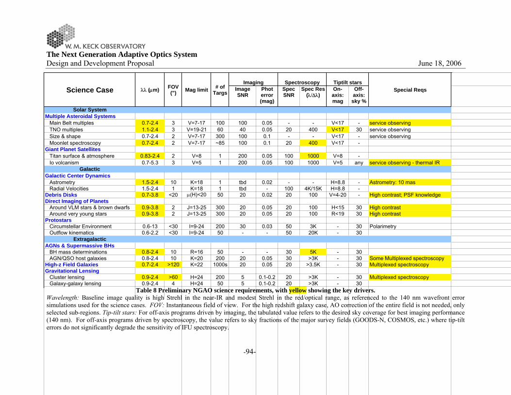
The Next Generation Adaptive Optics System Design and Development Proposal June 18, 2006
-94-
Table 8 Preliminary NGAO science requirements, with yellow showing the key drivers. Wavelength: Baseline image quality is high Strehl in the near-IR and modest Strehl in the red/optical range, as referenced to the 140 nm wavefront error simulations used for the science cases. FOV: Instantaneous field of view. For the high redshift galaxy case, AO correction of the entire field is not needed, only selected sub-regions. Tip-tilt stars: For off-axis programs driven by imaging, the tabulated value refers to the desired sky coverage for best imaging performance (140 nm). For off-axis programs driven by spectroscopy, the value refers to sky fractions of the major survey fields (GOODS-N, COSMOS, etc.) where tip-tilt errors do not significantly degrade the sensitivity of IFU spectroscopy.
Image SNR
Phot error (mag)
Spec SNR
Spec Res (λ/Δλ)
On-axis: mag
Off-axis:
sky %Solar System
Multiple Asteroidal Systems Main Belt multiples 0.7-2.4 3 V=7-17 100 100 0.05 - - V<17 - service observing TNO multiples 1.1-2.4 3 V=19-21 60 40 0.05 20 400 V<17 30 service observing Size & shape 0.7-2.4 2 V=7-17 300 100 0.1 - - V<17 - service observing Moonlet spectroscopy 0.7-2.4 2 V=7-17 ~85 100 0.1 20 400 V<17 -Giant Planet Satellites Titan surface & atmosphere 0.83-2.4 2 V=8 1 200 0.05 100 1000 V=8 - Io volcanism 0.7-5.3 3 V=5 1 200 0.05 100 1000 V=5 any service observing - thermal IR
GalacticGalactic Center Dynamics Astrometry 1.5-2.4 10 K=18 1 tbd 0.02 - - H=8.8 - Astrometry: 10 mas Radial Velocities 1.5-2.4 1 K=18 1 tbd - 100 4K/15K H=8.8 -Debris Disks 0.7-3.8 <20 μ(H)<20 50 20 0.02 20 100 V=4-20 - High contrast; PSF knowledgeDirect Imaging of Planets Around VLM stars & brown dwarfs 0.9-3.8 2 J=13-25 300 20 0.05 20 100 H<15 30 High contrast Around very young stars 0.9-3.8 2 J=13-25 300 20 0.05 20 100 R<19 30 High contrastProtostars Circumstellar Environment 0.6-13 <30 I=9-24 200 30 0.03 50 3K - 30 Polarimetry Outflow kinematics 0.6-2.2 <30 I=9-24 50 - - 50 20K - 30
ExtragalacticAGNs & Supermassive BHs BH mass determinations 0.8-2.4 10 R=16 50 - - 30 5K - 30 AGN/QSO host galaxies 0.8-2.4 10 K=20 200 20 0.05 30 >3K - 30 Some Multiplexed spectroscopyHigh-z Field Galaxies 0.7-2.4 >120 K=22 1000s 20 0.05 20 >3.5K - 30 Multiplexed spectroscopyGravitational Lensing Cluster lensing 0.9-2.4 >60 H=24 200 5 0.1-0.2 20 >3K - 30 Multiplexed spectroscopy Galaxy-galaxy lensing 0.9-2.4 4 H=24 50 5 0.1-0.2 20 >3K - 30
Science Case λλ (μm) FOV (") Mag limit
Tiptilt starsSpecial Reqs
Imaging# of
Targs
Spectroscopy

The Next Generation Adaptive Optics System Design and Development Proposal June 18, 2006
-95-
A high-level summary of the basic AO concept requirements is presented in Table 9, listed by science topic and relative importance of each major AO capability. The impact of optical (modest Strehl) and near-IR (high Strehl) AO performance is broad and/or fundamental to all major science areas. Thermal near-IR performance is ancillary and not a strong driver. High contrast performance is very significant, especially for Galactic science.
Table 9 Summary of overall AO concept requirements by science area.
Optical Near-IR Thermal-NIRnarrow field, modest Strehl
narrow field, high Strehl
narrow field, v.high Strehl
Solar System Key Yes Yes Maybe -
Galactic Yes Key Maybe Key -
Extragalactic Key Key - Yes Key
Parameter Space of Possible AO Systems
High Contrast
Wide-Field, Multi-Object
In terms of this broad parameter space, the one significant discrepancy between the requirements of the different science areas is field of view. The solar system and galactic cases only use a narrow field (<10"). However, extragalactic astronomy would benefit enormously from wider field-of-view. In particular, faint, high redshift galaxies have a sufficiently large surface density on the sky, a few to tens per square arcmin (section 3.4.2). Therefore, a spectroscopic multiplexing capability over a few square arcmin would be a very powerful new tool for high redshift studies provided by NGAO. There are no specific science programs that demand queue-scheduled observations. However, several programs to monitor time-variable phenomena could obviously be observed more efficiently with queue scheduling. In addition, queue scheduling would be the most efficient means to maximize the science return from NGAO, which will depend on the observing conditions (atmospheric seeing profile and sodium layer properties). This is especially true at the blue end of the optical performance, relevant for science programs demanding the very best angular resolution. Thus, the NGAO operating model should allow for potential implementation of queue scheduling. Science Instruments: A prioritized list of science instrument options is provided in Table 10 for each of the major science areas. These are an overall summary for each of the individual science cases; overall, there is good agreement within a given science area (planetary, galactic and extragalactic) for the science instruments. Further discussion of the science instrument characteristics and overall prioritization is given in section 4.3.3.4.
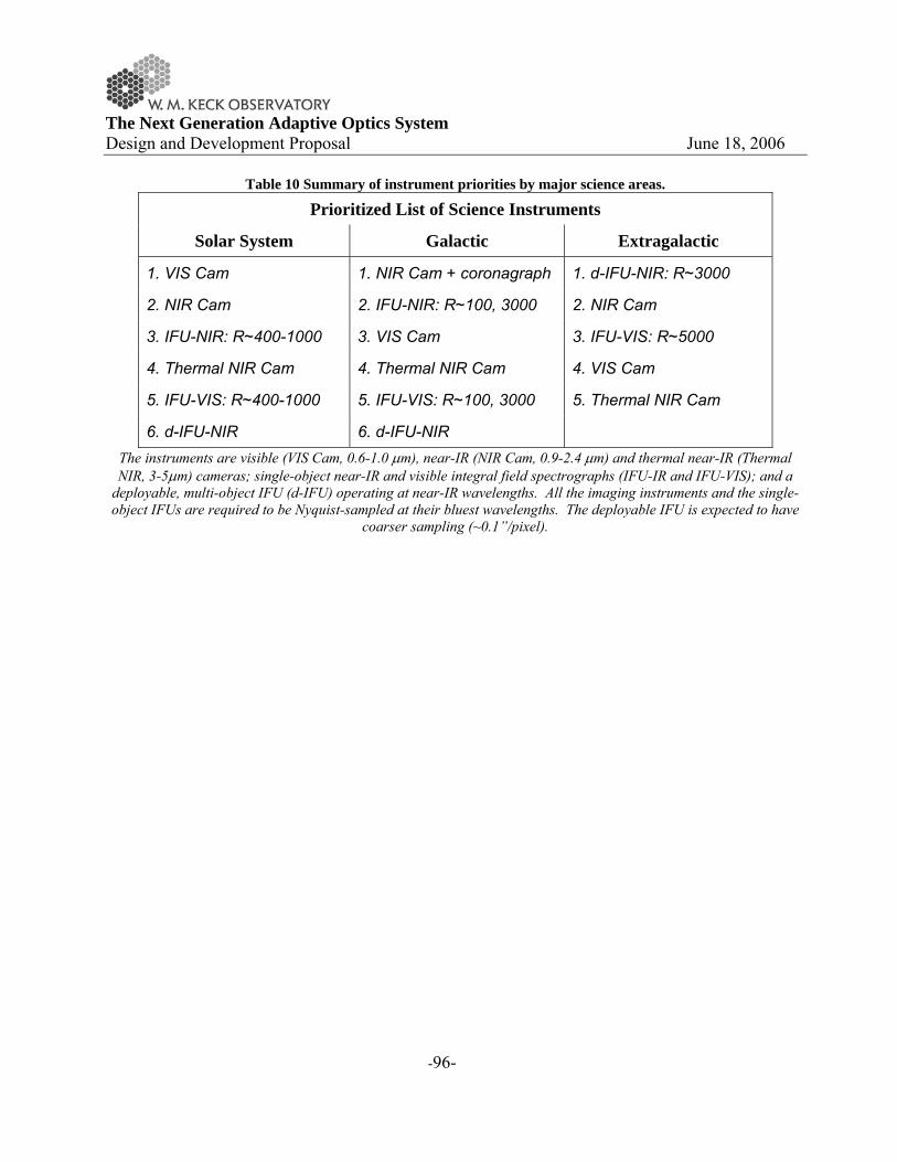
The Next Generation Adaptive Optics System Design and Development Proposal June 18, 2006
-96-
Table 10 Summary of instrument priorities by major science areas.
Prioritized List of Science Instruments
Solar System Galactic Extragalactic
1. VIS Cam 1. NIR Cam + coronagraph 1. d-IFU-NIR: R~3000
2. NIR Cam 2. IFU-NIR: R~100, 3000 2. NIR Cam
3. IFU-NIR: R~400-1000 3. VIS Cam 3. IFU-VIS: R~5000
4. Thermal NIR Cam 4. Thermal NIR Cam 4. VIS Cam
5. IFU-VIS: R~400-1000 5. IFU-VIS: R~100, 3000 5. Thermal NIR Cam
6. d-IFU-NIR 6. d-IFU-NIR The instruments are visible (VIS Cam, 0.6-1.0 μm), near-IR (NIR Cam, 0.9-2.4 μm) and thermal near-IR (Thermal NIR, 3-5μm) cameras; single-object near-IR and visible integral field spectrographs (IFU-IR and IFU-VIS); and a
deployable, multi-object IFU (d-IFU) operating at near-IR wavelengths. All the imaging instruments and the single-object IFUs are required to be Nyquist-sampled at their bluest wavelengths. The deployable IFU is expected to have
coarser sampling (~0.1”/pixel).

The Next Generation Adaptive Optics System Design and Development Proposal June 18, 2006
-97-
4 TECHNICAL
4.1 Introduction
It is clear that the scientific requirements for the NGAO system are very challenging. In developing a proposal for the system design phase of the NGAO system some effort was needed to provide a reasonable starting point for simulations of the performance of NGAO for the various science cases. This required us to make an initial pass through the key iterative cycle of the system design process. This cycle consists of considering the science requirements and their technical implications, conceiving of a point design system architecture to meet those requirements, assessing the performance that such a system might deliver and then repeating as required while considering a number of engineering trade-offs to arrive at the best architecture that will meet the science requirements while minimizing technical and cost risk. The point design discussed here is only intended to demonstrate the feasibility of meeting the science requirements and is not intended to represent the optimal system architecture. The key elements of an AO system capable of delivering both high Strehls and wide fields are illustrated in Figure 39. A sodium wavelength laser is needed to provide high sky coverage and good correction. The laser light is transported from a laser enclosure to behind the telescope’s secondary mirror (to minimize spot elongation) by single mode fibers or a beam transport system. Multiple LGS beacons are projected (to correct for focal anisoplanatism) through a projection telescope. The light from the science object, several NGS and the LGS, is sent into the AO enclosure. An optical relay sends the light off one or more deformable mirrors and outputs a converging beam to an optical switchyard. The visible and infrared light is appropriately distributed in the optical switchyard to the wavefront sensors and the science instruments. Multiple wavefront sensors are required to observe several NGS both at high bandwidth (for tip-tilt correction) and low bandwidth (for focus and LGS aberration correction) and the multiple LGS. Multiple science instruments, in both the visible and infrared, are required to achieve the range of science goals.
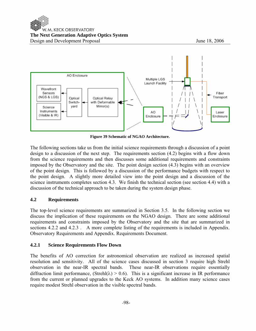
The Next Generation Adaptive Optics System Design and Development Proposal June 18, 2006
-98-
Figure 39 Schematic of NGAO Architecture.
The following sections take us from the initial science requirements through a discussion of a point design to a discussion of the next step. The requirements section (4.2) begins with a flow down from the science requirements and then discusses some additional requirements and constraints imposed by the Observatory and the site. The point design section (4.3) begins with an overview of the point design. This is followed by a discussion of the performance budgets with respect to the point design. A slightly more detailed view into the point design and a discussion of the science instruments completes section 4.3. We finish the technical section (see section 4.4) with a discussion of the technical approach to be taken during the system design phase. 4.2 Requirements
The top-level science requirements are summarized in Section 3.5. In the following section we discuss the implication of these requirements on the NGAO design. There are some additional requirements and constraints imposed by the Observatory and the site that are summarized in sections 4.2.2 and 4.2.3 . A more complete listing of the requirements is included in Appendix. Observatory Requirements and Appendix. Requirements Document. 4.2.1 Science Requirements Flow Down
The benefits of AO correction for astronomical observation are realized as increased spatial resolution and sensitivity. All of the science cases discussed in section 3 require high Strehl observation in the near-IR spectral bands. These near-IR observations require essentially diffraction limit performance, (Strehl(λ) > 0.6). This is a significant increase in IR performance from the current or planned upgrades to the Keck AO systems. In addition many science cases require modest Strehl observation in the visible spectral bands.

The Next Generation Adaptive Optics System Design and Development Proposal June 18, 2006
-99-
To be truly useful this high Strehl is required for objects that are intrinsically faint (V<25). Using such objects as the higher order wavefront sensing reference is impossible with any plausible technology and was the justification for the current LGS system. However, the quality of the wavefront correction from one LGS will be limited1 by its sampling of turbulence over a conical volume of the atmosphere. NGAO must use several LGS for its higher order AO correction in order to overcome the limitation due to the cone effect (also known as focus anisoplanatism). Many of the science cases in the Solar System and Galactic areas have requirements for relatively small corrected fields of view that are close to the isoplanatic patch size (~10″). The target density on the sky is low so that only one target would be observed at a time. It would be possible to correct the wavefront for this single line of sight with one deformable mirror. However, many of the extragalactic science cases need the ability to perform multi-object observations, each requiring a relatively small field of view in a larger field of regard. An example would be observation of each member of a distant cluster of galaxies. To appreciate the value of multiplex AO observations one need only consider that an OSIRIS observation of a single galaxy can take up to 8 hours. Two types of AO architectures can provide a multiplex AO correction; these are multiple object AO (MOAO) and multi-conjugate AO (MCAO). In MOAO separate deformable mirrors work in parallel with one assigned to correct a small patch around each science object, these individual AO corrected patches are ~10 arcsec in size. This architecture is a natural fit to the galaxy cluster type observations mentioned above. A second type of multiplexed AO system is MCAO, in this architecture the deformable mirrors are allocated to correction of individual turbulent layers, resulting in correction across a contiguous field of view. The MCAO approach is thought to come at a somewhat decreased level of peak Strehl performance and a somewhat smaller field of view. The technical team considered each of these architectures in terms of their multiplex advantage for AO observations. The conclusion was that each one is best suited to certain types of science observations, and thus no clear winner can be decided based on scientific merit or technical utility at the present preliminary stage in our design process. The NGAO point design presented in this proposal has the flexibility to support both MCAO and MOAO architectures. At present a fundamental limitation of laser guide stars is the need to measure wavefront tip-tilt from a natural guide star. The exact performance of any LGS AO system is a complex function of the number, location and brightness of the available natural tip-tilt stars. At present with the current visible tip-tilt system the Keck II LGS system is limited to natural guide stars of 15th magnitude2 or brighter for no degradation in performance compared to bright stars. The same limiting magnitude for NGAO would be unacceptable from the point of view of the number of targets that could be observed with high Strehl.
1 If left uncorrected this one error would be equal to the entire rms wavefront error budget for the NGAO point design. 2 The LGS system can track on stars between 15 and 18 magnitude but the errors in tip-tilt correction are rapidly becoming the limiting factor.
The Next Generation Adaptive Optics System Design and Development Proposal June 18, 2006
-100-
The implied sky coverage requirements from the science case resulted in several strategies to improve sky coverage. The tip-tilt reference star must be observed in the near-IR window where the star can be partially corrected by the AO system. This sharpened guide star provides an improvement in tracking that is in direct proportion to the decrease in FHWM between a seeing limited and AO corrected image, and enables the use of dimmer tip-tilt reference stars. In order to have a large probability of locating such a star the AO correction must cover a significant fraction of the sky around the science object. In the case of MCAO the corrected field of view must be around 2 arcmin diameter. For MOAO correction, an MOAO unit must be dedicated to each tip-tilt star and the MOAO unit must be able to patrol a similar 2 arcmin field. The requirement for high sky coverage is not limited to extragalactic science cases, many of the proposed planetary and galactic science cases also have science objects that are too faint to provide accurate tip-tilt references. In these cases MOAO or MCAO type correction is needed to be able to use field stars as the tip-tilt reference while maintaining high Strehl. The technical team has attempted to balance the desires for all sky observation and highest possible Strehl in the NGAO point design. Another important area scientifically for NGAO is high contrast observations. The Strehl proposed for NGAO is lower than extreme AO systems such as the GEMINI planet imager. NGAO provides a unique combination of high contrast capability with a sky coverage that greatly exceeds that of an NGS-only extreme AO system. The exact level of achievable contrast will be dependent on controlling systematic errors. Systematic error that need to special attention are diffraction from the telescope aperture, “quasi static” speckle resulting from uncorrectable and non-common path wavefront errors. A further benefit of high Strehl AO is the resulting stability of the point spread function which enables increased precision in photometric observations. The required photometric accuracies range between 0.01 and 0.1 magnitudes depending on the exact observing scenario. Most science programs that require the highest photometric accuracy are those where the science object provided a bright (H < 16) tip-tilt sensing star. In addition to high Strehl, photometric accuracy also places requirements on NGAO to be able to calibrate the point spread function accurately either during the observation or afterward from stored AO telemetry. Astrometric accuracy is also enhanced by improved AO correction. For the Galactic Center the required accuracy is 0.1 mas. This positional accuracy requires a high Strehl to reduce the confusion between the point sources located around Sgr A*. Because of the fortuitously close tip/tilt guide star IRS-7 the ability to tip-tilt track in the near-IR is a derived requirement for NGAO for this science case. The required level of astrometric accuracy also demands tighter tolerances on the mechanical stability of the AO system and instruments as compared to the current Keck AO systems. It is almost a fundamental rule of observational astronomy that the most interesting scientific targets are the faintest. Observation of such objects require using the highest throughput optical coatings possible and minimizing the number of surfaces. At the far end of the near infrared (K, L

The Next Generation Adaptive Optics System Design and Development Proposal June 18, 2006
-101-
and M-bands) many objects will have a surface brightness significantly below the sky background. For these sources reduction of the AO systems emissivity is also a requirement. For the point design we adopted an optical design with few surfaces and placed the AO system in a cooled enclosure. This requirement could be better met with an adaptive secondary mirror. The technical team has selected what appears to be, at the present time, a lower risk conventional AO relay for the point design. In summary the primary functions of the NGAO system to meet the science requirements are:
• Near diffraction-limited AO correction in the near-IR (high Strehl, low rms wavefront
error) • Modest Strehl, FWHM ~ λ/D, for visible observations (0.60 to 1.0 μm) • High sky coverage for AO correction • Ability to multiplex AO observations • High optical transmission • Low IR background • Calibration and control of AO systematic effects on observations
In order to fulfill these requirements the technical team decided that NGAO must consist of the following components/features:
• Multiple laser guide stars (sky coverage, multiplex, Strehl) • Measurement of the 3-D turbulence structure (sky coverage, multiplex, Strehl, calibration) • AO correcting elements with on order of 1000 actuators (Strehl) • Multiple AO corrector elements (sky, multi, Strehl) • Optical fields of up to an 2 arcmin (4 as goal) (TT sky coverage, multiplex) • Use of multiple natural guide stars for tip/tilt correction (TT sky coverage) • Separate AO correction for natural tip/tilt guide stars (TT sky coverage) • Use of the fewest number of optics (Transmission, IR background) • Cooling of AO system (IR background)
These features of NGAO are discussed further in section 4.3. 4.2.2 Observatory Requirements
The exact location of NGAO in the current WMKO facility will impose a number of requirements on the system. The following issues are noted as some of the most important to resolve during the NGAO system design. The Keck telescope foci and Nasmyth deck storage locations are already heavily utilized. The current AO systems occupy the left Nasmyth platform locations of both telescopes. HIRES

The Next Generation Adaptive Optics System Design and Development Proposal June 18, 2006
-102-
occupies the right Nasmyth on Keck I while DEIMOS and NIRSPEC share the right Nasmyth on Keck II. The Cassegrain foci are occupied by LRIS (and MOSFIRE in the future) on Keck I and by ESI on Keck II. The bent Cassegrain ports are believed to have inadequate space and weight capacities. The most viable option appears to be one of the Nasmyth platforms is in the location of an existing AO system. The Keck interferometer (KI) dual star modules (DSM) currently move into both AO enclosures on rails to feed the KI. The requirement to feed the KI requires that collimated light can be fed to the DSM and that the field rotation, pupil rotation, longitudinal dispersion and polarization from the NGAO system and the AO system on the other telescope be identical. The Keck I telescope LGS AO system should be our highest performance AO system. In order to best serve the AO observing community during the installation of NGAO we believe that NGAO should therefore be installed in place of the existing Keck II AO system (NIRC2 could be moved to Keck I). Support for the Interferometer during and after the NGAO installation needs to be addressed. 4.2.3 Mauna Kea Site Conditions
To provide the NGAO point design with the latest information regarding atmospheric turbulence conditions at WMKO, an evaluation of existing seeing data has been performed (KAON 303). The KAON 303 profile was modified to include a stronger ground layer and the standard r0 value was lowered from 20 to 18 cm. The resultant baseline median Cn
2 profile is presented in Table 11. From this model we calculate the following turbulence parameters for 0.5 μm wavelength (note that r0, θ0 and 1/fG increase as λ6/5):
• Fried’s seeing parameter r0 = 18 cm • Isoplanatic angle θ0 = 2.5 arcsec • Turbulence characteristic frequency fG = 39 Hz
In addition, where relevant to our studies, we have adopted a standard deviation of r0 of σr0 = 3 cm with a characteristic evolution time of t = 3 min.
Table 11 Mauna Kea Cn2 Profile. Altitude (km) Fractional Cn
2 Wind Speed (m/s) 0.0 0.471 6.7 2.1 0.184 13.9 4.1 0.107 20.8 6.5 0.085 29.0 9.0 0.038 29.0 12.0 0.093 29.0 14.8 0.023 29.0

The Next Generation Adaptive Optics System Design and Development Proposal June 18, 2006
-103-
A median outer scale of 75 m is assumed (Dekens, PhD thesis). The atmospheric surface pressure is assumed to be 600 mbars and the average ambient temperature is 0°C. The above values will be updated as new Cn
2 monitoring data are obtained, primarily as part of the current TMT site survey effort. An evaluation of existing sodium density data has been performed resulting in the use of a median sodium density of 4x10⁹ atoms/cm2. This value was derived from data taken with the University of Illinois LIDAR system located at Haleakala on Maui on 35 nights spread over a 4 year period. Except where noted otherwise we have use these site conditions as baselines in determining the NGAO performance. 4.3 Point Design
4.3.1 Point Design Overview
An initial NGAO point design has been developed to demonstrate the feasibility of satisfying the science requirements, to evaluate the areas of complexity and risk, and to use for cost estimation purposes. This design should only be regarded as one possible approach to satisfying the requirements; other potential designs architectures will be considered and numerous design trade studies will be performed to determine the optimal approach to meeting the NGAO science requirements. The point design consists of multiple LGSs for atmospheric tomography, a basic AO relay (Figure 40), and a dichroic switchyard (Figure 42) to divide the light amongst the science instruments and wavefront sensors. The point design has been developed to enable both the science that requires high Strehl ratios (at the cost of narrow fields) and the science that requires a wider field (at the cost of lower Strehls) via an adjustable placement of the LGSs as illustrated in Figure 43. The optical relay (Figure 40) begins with a window that isolates the AO enclosure from the dome environment while also acting as a field lens. As in the existing AO system a K-mirror rotator is used to correct for image rotation and a pair of identical off-axis parabolas (OAPs) are used. The first OAP collimates the light and reimages the telescope primary mirror onto the deformable mirror (DM). The DM is mounted on a fast tip/tilt stage. The second OAP reconverges the light with the same f/# and pupil location as initially provided by the telescope. The first OAP was chosen to be conjugate to a high altitude (9.0 km) to allow the capability of converting this OAP into a DM in order to provide a multi-conjugate AO (MCAO) option. The size of the optical relay is driven by the telescope’s f/13.66 focal ratio (corresponding to a 10.949 m circumscribed primary mirror), the choice of field size (4 arcmin) and the size of the DM. The DM size is driven by the number of actuators (chosen to be 63 actuators from edge-to-edge of the 10.949 m primary mirror) and the actuator spacing (chosen to be 3.5 mm). The OAP
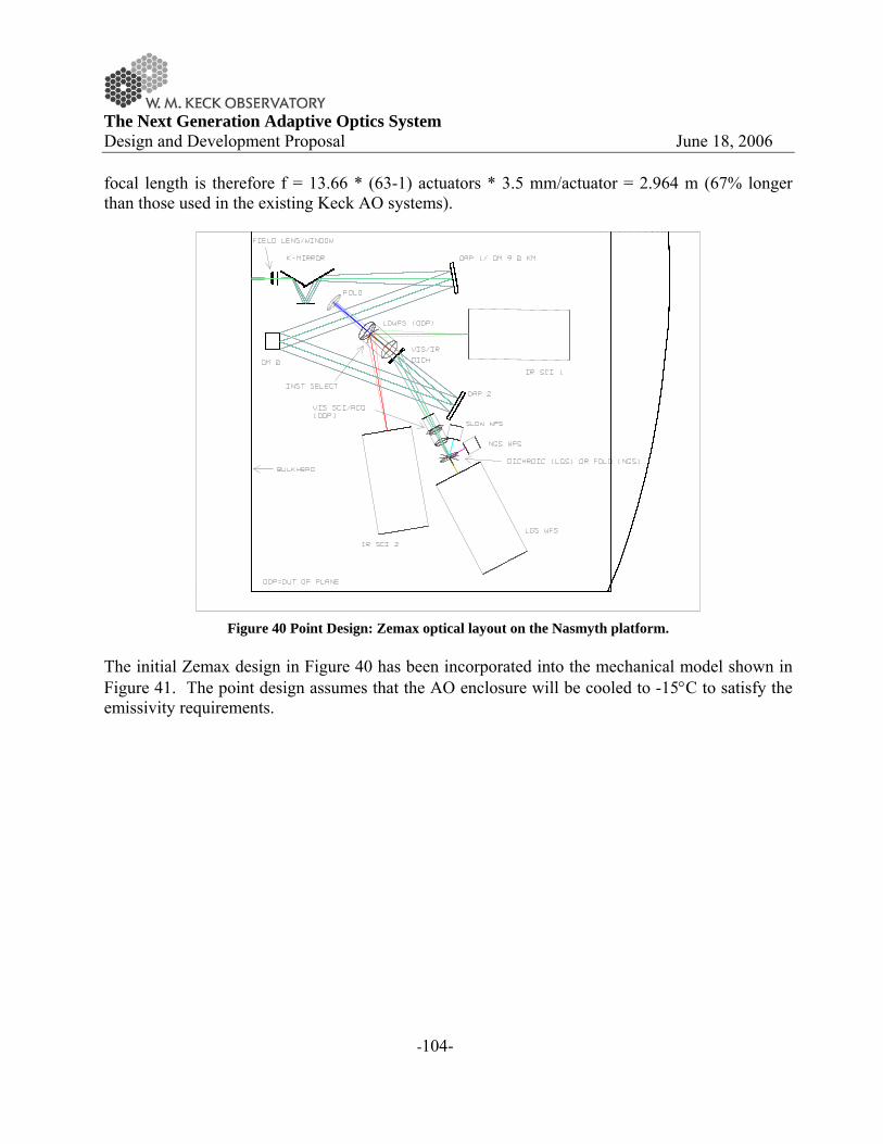
The Next Generation Adaptive Optics System Design and Development Proposal June 18, 2006
-104-
focal length is therefore f = 13.66 * (63-1) actuators * 3.5 mm/actuator = 2.964 m (67% longer than those used in the existing Keck AO systems).
Figure 40 Point Design: Zemax optical layout on the Nasmyth platform.
The initial Zemax design in Figure 40 has been incorporated into the mechanical model shown in Figure 41. The point design assumes that the AO enclosure will be cooled to -15°C to satisfy the emissivity requirements.

The Next Generation Adaptive Optics System Design and Development Proposal June 18, 2006
-105-
Figure 41 NGAO system on the Keck left Nasmyth platform.
The distribution of the light between the science instruments and various wavefront sensors can be seen more clearly in the schematic shown in Figure 42. This schematic is also useful for identifying the various sensors. The first dichroic transmits the long wavelength light through an atmospheric dispersion corrector to the IR science instruments and a Low Order (LO) WaveFront Sensor (WFS) assembly. The LOWFS assembly consists of three near-IR pyramid sensors used to sense tip, tilt, focus and astigmatism from three NGS located randomly over the field. Each LOWFS unit includes a 32x32 actuator MEMs to provide MOAO-correction. The LOWFS uses the wavelengths not currently used by the IR science instruments with the assistance of a changeable dichroic that reflects the light to the science instruments. The short wavelength light reflected by the first dichroic goes to a second dichroic that divides the light between the various visible wavelength detectors. The reflected light goes to the visible science instrument and a NGS acquisition camera (ACAM). The short wavelength transmitted light goes to a slow WFS and the LGS WFS assembly. The LGS assembly includes an LGS acquisition camera and multiple Shack-Hartmann LGS WFS. The LGS assembly is mounted on a translation stage used to keep the assembly conjugate to the sodium layer. The slow (Shack-Hartmann) WFS acts as a truth sensor by monitoring an NGS in order to correct for aberrations introduced by the LGS. In NGS AO mode only the NGS (Shack-Hartmann) WFS is used (the LOWFS, visible slow WFS and LGS WFS are not required).
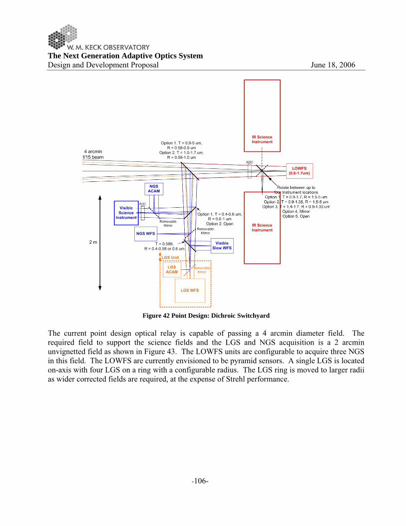
The Next Generation Adaptive Optics System Design and Development Proposal June 18, 2006
-106-
Figure 42 Point Design: Dichroic Switchyard
The current point design optical relay is capable of passing a 4 arcmin diameter field. The required field to support the science fields and the LGS and NGS acquisition is a 2 arcmin unvignetted field as shown in Figure 43. The LOWFS units are configurable to acquire three NGS in this field. The LOWFS are currently envisioned to be pyramid sensors. A single LGS is located on-axis with four LGS on a ring with a configurable radius. The LGS ring is moved to larger radii as wider corrected fields are required, at the expense of Strehl performance.

The Next Generation Adaptive Optics System Design and Development Proposal June 18, 2006
-107-
Figure 43 Point Design: NGAO transmitted field showing LGS asterism, NGS and science field.
One key feature of the point design is that different numbers of subapertures and actuators are required to achieve the required wavefront performance budget. Figure 44 shows the registration of the DM actuators and WFS subapertures to the DM.
Figure 44 Point Design: DM actuators and WFS subapertures projected onto the Keck telescope pupil.
The massively parallel processing (MPP) system pipeline architecture shown in Figure 45 has been chosen for the point design. Investigation of the algorithms and data flow needed for real-time processing and control has suggested that a MPP architecture using current state-of-the-art field programmable gate arrays (FPGAs) can readily accomplish the NGAO task.

The Next Generation Adaptive Optics System Design and Development Proposal June 18, 2006
-108-
In this approach, multiple wavefront sensors, one for each LGS and NGS, feed data to a centralized tomography unit. The tomography unit determines an estimate of the differential optical path differences within volume elements of a model atmosphere. This information is then used to project along paths to the DM(s) in the optical relay and the DMs in the MOAO units. The MPP architecture has the advantage that it can scale with the number of guide stars, number of DMs, and number of subapertures by simply adding processor cards without affecting the data throughput rate or the software program significantly.
ImageProcessorsImage
ProcessorsImageProcessorsImage
Processors
WavefrontSensorsWavefront
SensorsWavefrontSensorsWavefront
SensorsTomography
Unit
ImageProcessorsImage
ProcessorsImageProcessorsDM
Fit
WavefrontSensorsWavefront
SensorsWavefrontSensorsDMProjection
DM conjugatealtitude
Cn2 profile Actuatorinfluencefunction
Centroid algorithmr0, guidstar brightness,
Guidestar position
ImageProcessorsImage
ProcessorsImageProcessorsDeformable
Mirrors
ImageProcessorsImage
ProcessorsImageProcessorsImage
Processors
WavefrontSensorsWavefront
SensorsWavefrontSensorsWavefront
SensorsTomography
Unit
ImageProcessorsImage
ProcessorsImageProcessorsDM
Fit
WavefrontSensorsWavefront
SensorsWavefrontSensorsDMProjection
DM conjugatealtitude
Cn2 profile Actuatorinfluencefunction
Centroid algorithmr0, guidstar brightness,
Guidestar position
ImageProcessorsImage
ProcessorsImageProcessorsDeformable
Mirrors
Figure 45 Multi-guidestar AO processing architecture The point design assumes three 50 W mode-locked CW lasers, similar to the 50 W laser currently being built by LM/CTI for Gemini Observatory. The lasers will be housed in an enclosure on or below one of the Nasmyth platforms. Each LGS will be routed via a separate photonic crystal fiber to a 50 cm diameter projection telescope located behind the f/15 secondary mirror. All of these technologies (laser, fiber and on-axis projection telescope) will be demonstrated in the development of the Keck I LGS AO facility. Other potential approaches to meeting the science requirements have been identified and will be evaluated during the system design phase to determine their relative merits. 4.3.2 Point Design Performance versus Requirements
In the following sections we evaluate the performance of the point design versus the flowed down requirements. A summary of the relevant flowed down requirements (compiled in Appendix. Requirements Document) is given at the start of each section.
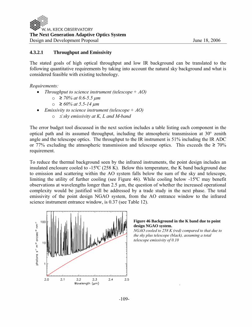
The Next Generation Adaptive Optics System Design and Development Proposal June 18, 2006
-109-
4.3.2.1 Throughput and Emissivity
The stated goals of high optical throughput and low IR background can be translated to the following quantitative requirements by taking into account the natural sky background and what is considered feasible with existing technology. Requirements:
• Throughput to science instrument (telescope + AO) o ≥ 70% at 0.6-5.5 μm o ≥ 60% at 5.5-14 μm
• Emissivity to science instrument (telescope + AO) o ≤ sky emissivity at K, L and M-band
The error budget tool discussed in the next section includes a table listing each component in the optical path and its assumed throughput, including the atmospheric transmission at 30° zenith angle and the telescope optics. The throughput to the IR instrument is 51% including the IR ADC or 77% excluding the atmospheric transmission and telescope optics. This exceeds the ≥ 70% requirement. To reduce the thermal background seen by the infrared instruments, the point design includes an insulated enclosure cooled to -15ºC (258 K). Below this temperature, the K band background due to emission and scattering within the AO system falls below the sum of the sky and telescope, limiting the utility of further cooling (see Figure 46). While cooling below -15ºC may benefit observations at wavelengths longer than 2.5 µm, the question of whether the increased operational complexity would be justified will be addressed by a trade study in the next phase. The total emissivity of the point design NGAO system, from the AO entrance window to the infrared science instrument entrance window, is 0.37 (see Table 12).
Figure 46 Background in the K band due to point design NGAO system. NGAO cooled to 258 K (red) compared to that due to the sky plus telescope (black), assuming a total telescope emissivity of 0.10
.

The Next Generation Adaptive Optics System Design and Development Proposal June 18, 2006
-110-
Table 12 Emissivity and temperature of each element in the IR science path. Component Effective emissivity Temperature CaF2 window bulk emission 7.5 x 10⁻⁴ 273 K CaF2 window reflection 0.02 258 K Rotator mirrors (3) 0.03 x 3 " Off-axis parabolas (2) 0.03 x 2 " Deformable mirror 0.03 " IR/visible dichroic bulk emission 5 x 10⁻⁴ " IR/visible dichroic reflection 0.05 " ADC prisms bulk emission (2) (1.5 x 10-3) x 2 " ADC prism reflections (2) 0.02 x 2 " IR dichroic reflection 0.05 " Science camera CaF2 window 5 x 10⁻⁴ "
Total 0.37 4.3.2.2 Wavefront Error Budget
Requirements: • Wavefront error budget (celestial sphere average, z=30°)
o ≤ 140 nm for 1% sky coverage o ≤ 160 nm for 20% sky coverage o ≤ 190 nm for 80% sky coverage
The wavefront error budgets for several key science cases have been evaluated and the results are summarized in Table 13 (Figure 1 provides a useful reference for converting the wavefront errors to Strehl). A discussion of the error budget tool and results is provided in Appendix. Wavefront Error Budget. Brief summaries of the key findings from this extensive discussion are included below.
Table 13 NGAO point design performance summary for several key science cases. Science Case
(typically under median conditions)
AO mode
Seeing Field of View
(arcsec)
RMS Wavefront Error (nm)
NGS mag or Sky Coverage
at H-band "Best-conditions" narrow-field 5 LGS Superior 2" 93 20% Io 1 NGS Median 1" 125 mV = 5.5 Kuiper Belt Object (KBO) 5 LGS Median 2" 131 mH = 15.75 Galactic Center (GC) 5 LGS Median 10" 182 mH = 8.8 (IRS7)Field Galaxies (sky-average) 5 LGS Median 2" 173 + 6 mas 30% Field Galaxies (d-IFU case) 5 LGS Median 2" 173+30 mas 90% GOODS-N Field 5 LGS Median 2" 218+16 mas 20% of G-N GOODS-N Field (d-IFU case) 5 LGS Median 2” H-band FWHM
≤50mas 75% of G-N

The Next Generation Adaptive Optics System Design and Development Proposal June 18, 2006
-111-
The wavefront error column of Table 13 includes the equivalent rms value that arises from tip/tilt errors (initially calculated in units of mas of residual tip/tilt to arrive at a Strehl ratio due to tip/tilt, which is then converted into an equivalent rms wavefront error). In the case of deployable-IFU science, we call out the high-order wavefront error terms separately from the tip/tilt contribution. Typically, NGAO d-IFU science will be optimized for spaxial scales of 50-100 mas, so that residual tip/tilt errors small compared to the spaxial scale can be ignored when computing SNR estimates. During the system design phase, we will treat cases like this using ensquared energy as the most appropriate science metric. 4.3.2.2.1 Narrow-field Science (KBO case)
The performance of the NGAO point design for the KBO case is shown in Figure 47 versus science target brightness for a variety of sky fractions. The optimal choice between target and field stars was used to produce this plot (the KBO was generally used for H ≤ 17). A classically scheduled KBO observing program (e.g., one in which telescope allocations are made in quanta of full-nights), would likely follow the behavior of the 30% sky coverage curve. Although multiple targets would need to be observed during any one night, some optimization within the night to catch favorable target appulses with field stars could be arranged. A typical error budget for this case, assuming a target having mH = 15.75 and science field of view of only 2 arcsec (e.g. OSIRIS observations), is shown in Appendix. Wavefront Error Budget.
Figure 47 NGAO point design performance vs KBO brightness b = 30° and zenith angle = 30° in median seeing.

The Next Generation Adaptive Optics System Design and Development Proposal June 18, 2006
-112-
4.3.2.2.2 Moderate-field Science (Galactic Center case)
The performance on the GC under median seeing conditions is dominated by high-order wavefront measurement error. GC observations in these conditions are limited by our point design choice of 150W of sodium laser power. Figure 48 presents the variation in H-band Strehl ratio as a function of seeing conditions, as indicated by the Fried parameter, r0. As the seeing improves, the contribution to the error due to finite laser guide star power falls, so that in good conditions, performance comparable to that nearer to zenith in median conditions is obtained.
Figure 48 NGAO point design Galactic Center performance versus seeing conditions, using IRS7 as the
tip/tilt/focus star. 4.3.2.2.3 Wide-field Deployable IFU Science (GOODS-N case)
The GOODS fields have been chosen specifically on dark patches of the sky at high Galactic latitude in order to avoid scattered light from Galactic field stars in science images. This leads to a dearth of natural tip/tilt star references that can be used for AO, making high Strehl ratio performance over large statistical sky fraction difficult. This is compounded by the fact that the GOODS fields are at relatively large zenith angle (45°) as seen from Mauna Kea. In this case, we assume a mode of NGAO where multiple deployable IFUs (d-IFU) and 5 LGS beacons are deployed over a 1.5 arcmin circular field of view, with the laser beacons on an
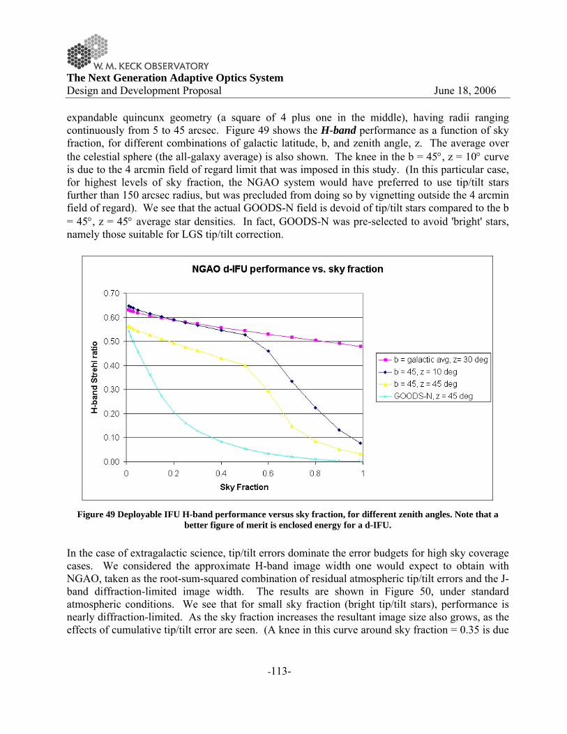
The Next Generation Adaptive Optics System Design and Development Proposal June 18, 2006
-113-
expandable quincunx geometry (a square of 4 plus one in the middle), having radii ranging continuously from 5 to 45 arcsec. Figure 49 shows the H-band performance as a function of sky fraction, for different combinations of galactic latitude, b, and zenith angle, z. The average over the celestial sphere (the all-galaxy average) is also shown. The knee in the b = 45°, z = 10° curve is due to the 4 arcmin field of regard limit that was imposed in this study. (In this particular case, for highest levels of sky fraction, the NGAO system would have preferred to use tip/tilt stars further than 150 arcsec radius, but was precluded from doing so by vignetting outside the 4 arcmin field of regard). We see that the actual GOODS-N field is devoid of tip/tilt stars compared to the b = 45°, z = 45° average star densities. In fact, GOODS-N was pre-selected to avoid 'bright' stars, namely those suitable for LGS tip/tilt correction.
Figure 49 Deployable IFU H-band performance versus sky fraction, for different zenith angles. Note that a
better figure of merit is enclosed energy for a d-IFU.
In the case of extragalactic science, tip/tilt errors dominate the error budgets for high sky coverage cases. We considered the approximate H-band image width one would expect to obtain with NGAO, taken as the root-sum-squared combination of residual atmospheric tip/tilt errors and the J-band diffraction-limited image width. The results are shown in Figure 50, under standard atmospheric conditions. We see that for small sky fraction (bright tip/tilt stars), performance is nearly diffraction-limited. As the sky fraction increases the resultant image size also grows, as the effects of cumulative tip/tilt error are seen. (A knee in this curve around sky fraction = 0.35 is due
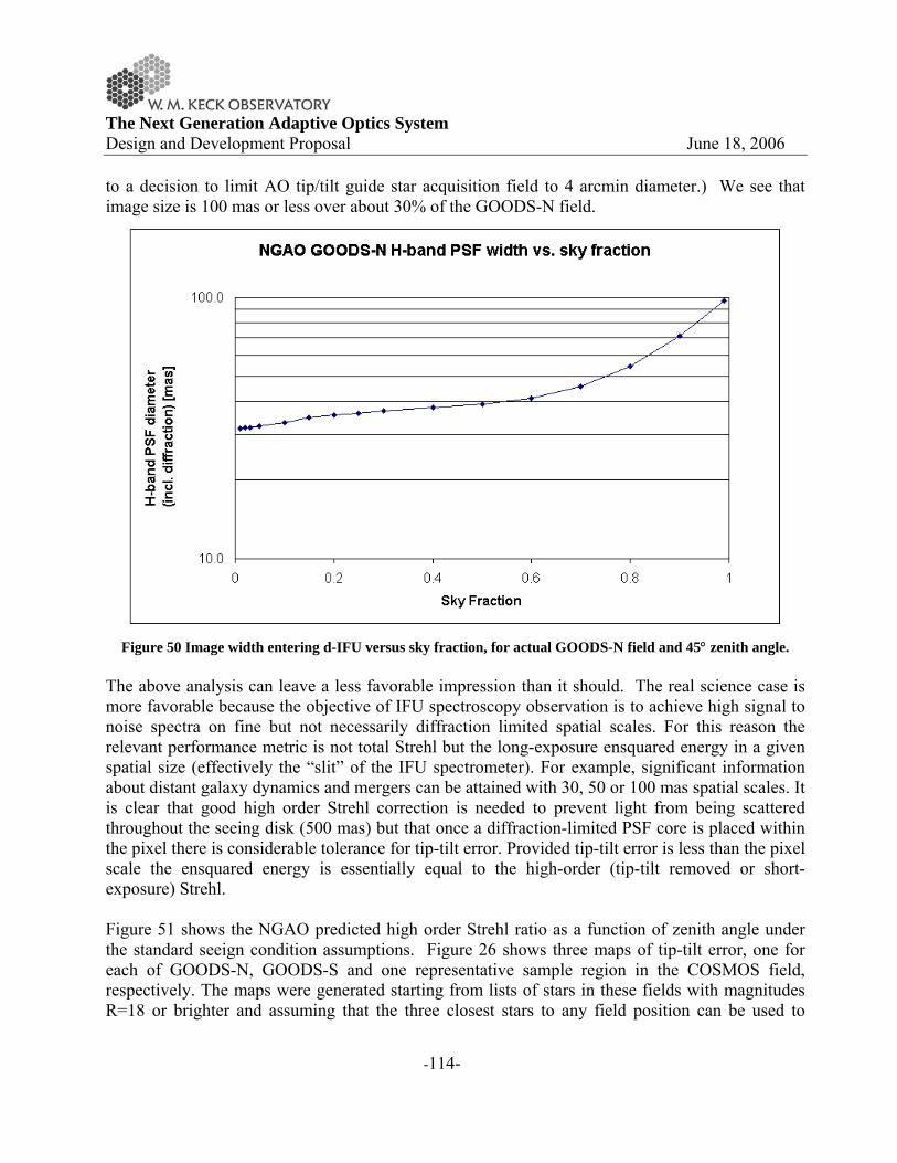
The Next Generation Adaptive Optics System Design and Development Proposal June 18, 2006
-114-
to a decision to limit AO tip/tilt guide star acquisition field to 4 arcmin diameter.) We see that image size is 100 mas or less over about 30% of the GOODS-N field.
Figure 50 Image width entering d-IFU versus sky fraction, for actual GOODS-N field and 45° zenith angle.
The above analysis can leave a less favorable impression than it should. The real science case is more favorable because the objective of IFU spectroscopy observation is to achieve high signal to noise spectra on fine but not necessarily diffraction limited spatial scales. For this reason the relevant performance metric is not total Strehl but the long-exposure ensquared energy in a given spatial size (effectively the “slit” of the IFU spectrometer). For example, significant information about distant galaxy dynamics and mergers can be attained with 30, 50 or 100 mas spatial scales. It is clear that good high order Strehl correction is needed to prevent light from being scattered throughout the seeing disk (500 mas) but that once a diffraction-limited PSF core is placed within the pixel there is considerable tolerance for tip-tilt error. Provided tip-tilt error is less than the pixel scale the ensquared energy is essentially equal to the high-order (tip-tilt removed or short-exposure) Strehl. Figure 51 shows the NGAO predicted high order Strehl ratio as a function of zenith angle under the standard seeign condition assumptions. Figure 26 shows three maps of tip-tilt error, one for each of GOODS-N, GOODS-S and one representative sample region in the COSMOS field, respectively. The maps were generated starting from lists of stars in these fields with magnitudes R=18 or brighter and assuming that the three closest stars to any field position can be used to

The Next Generation Adaptive Optics System Design and Development Proposal June 18, 2006
-115-
establish tip-tilt at that field position. As can be seen from these maps, the worst case situation, the center of the GOODS-N field, has a tip-tilt error of around 30 milliarcseconds. The COSMOS field, for comparison, has star statistics that are comparable to statistical models of star density (at the Galactic pole in this case) which are used in the statistical sky coverage analyses throughout this section. Throughout the COSMOS field (and, by implication most anywhere on the sky) the tip-tilt error is no more than 14 mas and has a median around 8 mas.
Figure 51 High order Strehl as a function of zenith angle.
The high order Strehl is generally equivalent to the ensquared energy in an IFU pixel provided the tip-tilt error is less than the pixel scale.
4.3.2.2.4 Best Conditions Narrow-field Science
We have generally considered the performance of the NGAO point design in median seeing, wind speed, and sodium abundance conditions for practical observing geometries. It is informative to consider the very best performance to be expected in the most favorable conditions, as both a reflection of the potential 'discovery space' of NGAO and to understand the issues NGAO will face as it follows an upgrade path toward better visible-light performance. While this is admittedly a rare coincidence of superior conditions and benign target distributions, these conditions are known to occasionally occur on Mauna Kea. In almost all ways, the atmospheric contributions to the error budget have dropped out, leaving us with a system limited by our own instrumentation and the Keck telescope itself. This raises a key question for the System Design phase of the NGAO project, namely ‘what is the extent to which the NGAO program requires facility upgrades to the telescope and existing instruments to realize it's potential’?. Ensuring that the performance of NGAO is not unduly degraded will require consideration of questions such as ‘can existing instruments be appropriately upgraded for NGAO,

The Next Generation Adaptive Optics System Design and Development Proposal June 18, 2006
-116-
or is an entirely new suite of instruments necessary?’ Similarly, we will consider whether improved diagnostics and, potentially, improved control of the Keck primary mirror is justified and/or necessary to meet the NGAO science goals. 4.3.2.2.5 Narrow-field NGS Science (Io case)
NGS AO remains an interesting mode of operation for both scientific and engineering purposes. Scientifically, the NGAO performance guiding on bright NGS will exceed that available in any foreseen LGS observing mode. The crossover brightness between NGS and LGS, the star brightness at which these two modes are comparable, is today about mV = 11. In other words, for NGS fainter than mV = 12, today's observer would typically obtain better performance in LGS mode. With the brighter laser return expected for NGAO, this crossover brightness will likely rise to mV = 8, making the use of NGS mode more specific to bright stellar targets and the brightness compact solar system objects (such as the Galilean satellites of Jupiter).
An error budget for Jupiter's moon Io was evaluated. The NGAO performance in median seeing conditions is excellent, with 102 nm rms wavefront error, reliably providing good Strehl ratio for R-band observations, including the (slightly) detrimental effect of the finite diameter of Io. We assume here good calibration of the high-order wavefront sensor so that no significant degradation, due to unknown centroid gains for example, is induced.
This particular example allows NGAO to utilize all N = 62 subapertures available in the point design. During the System Design phase, we will consider fainter NGS performance and consider issues such as the case for optimizing NGAO for faint (e.g. mV = 12-15) NGS.
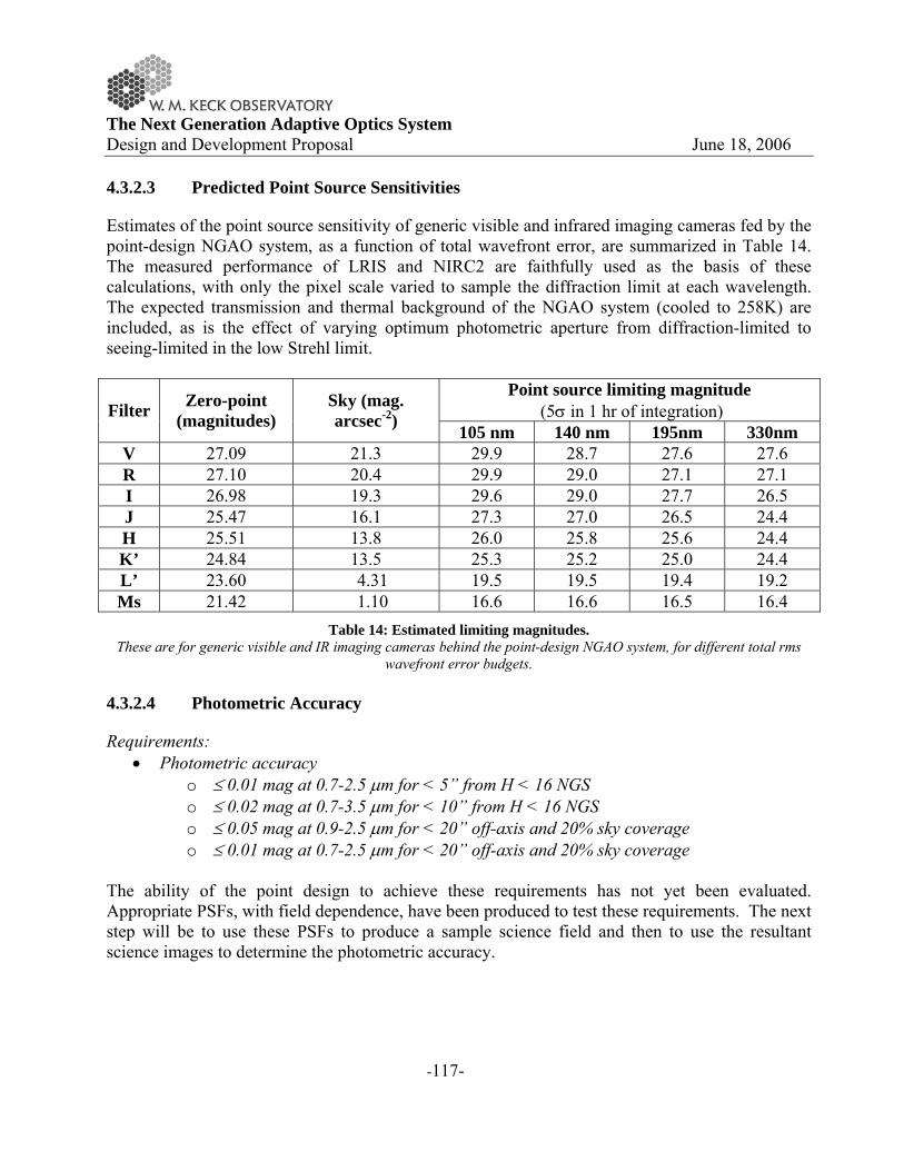
The Next Generation Adaptive Optics System Design and Development Proposal June 18, 2006
-117-
4.3.2.3 Predicted Point Source Sensitivities
Estimates of the point source sensitivity of generic visible and infrared imaging cameras fed by the point-design NGAO system, as a function of total wavefront error, are summarized in Table 14. The measured performance of LRIS and NIRC2 are faithfully used as the basis of these calculations, with only the pixel scale varied to sample the diffraction limit at each wavelength. The expected transmission and thermal background of the NGAO system (cooled to 258K) are included, as is the effect of varying optimum photometric aperture from diffraction-limited to seeing-limited in the low Strehl limit.
Point source limiting magnitude (5σ in 1 hr of integration) Filter Zero-point
(magnitudes) Sky (mag. arcsec-2)
105 nm 140 nm 195nm 330nm V 27.09 21.3 29.9 28.7 27.6 27.6 R 27.10 20.4 29.9 29.0 27.1 27.1 I 26.98 19.3 29.6 29.0 27.7 26.5 J 25.47 16.1 27.3 27.0 26.5 24.4 H 25.51 13.8 26.0 25.8 25.6 24.4 K’ 24.84 13.5 25.3 25.2 25.0 24.4 L’ 23.60 4.31 19.5 19.5 19.4 19.2 Ms 21.42 1.10 16.6 16.6 16.5 16.4
Table 14: Estimated limiting magnitudes. These are for generic visible and IR imaging cameras behind the point-design NGAO system, for different total rms
wavefront error budgets. 4.3.2.4 Photometric Accuracy
Requirements: • Photometric accuracy
o ≤ 0.01 mag at 0.7-2.5 μm for < 5” from H < 16 NGS o ≤ 0.02 mag at 0.7-3.5 μm for < 10” from H < 16 NGS o ≤ 0.05 mag at 0.9-2.5 μm for < 20” off-axis and 20% sky coverage o ≤ 0.01 mag at 0.7-2.5 μm for < 20” off-axis and 20% sky coverage
The ability of the point design to achieve these requirements has not yet been evaluated. Appropriate PSFs, with field dependence, have been produced to test these requirements. The next step will be to use these PSFs to produce a sample science field and then to use the resultant science images to determine the photometric accuracy.
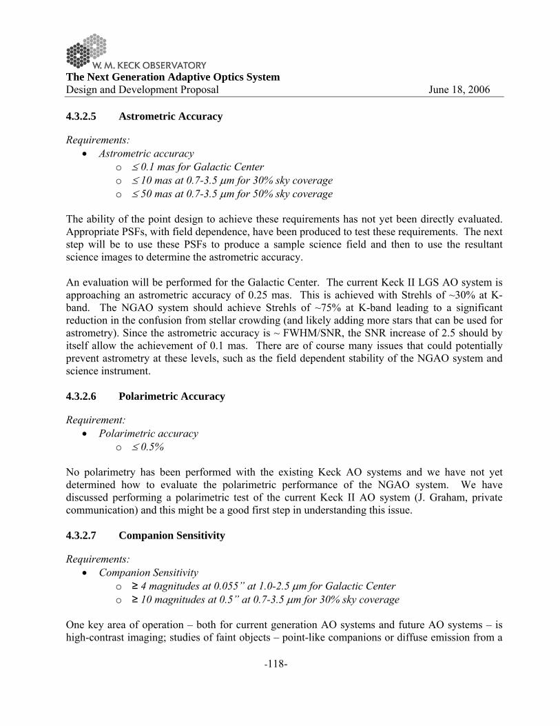
The Next Generation Adaptive Optics System Design and Development Proposal June 18, 2006
-118-
4.3.2.5 Astrometric Accuracy
Requirements: • Astrometric accuracy
o ≤ 0.1 mas for Galactic Center o ≤ 10 mas at 0.7-3.5 μm for 30% sky coverage o ≤ 50 mas at 0.7-3.5 μm for 50% sky coverage
The ability of the point design to achieve these requirements has not yet been directly evaluated. Appropriate PSFs, with field dependence, have been produced to test these requirements. The next step will be to use these PSFs to produce a sample science field and then to use the resultant science images to determine the astrometric accuracy. An evaluation will be performed for the Galactic Center. The current Keck II LGS AO system is approaching an astrometric accuracy of 0.25 mas. This is achieved with Strehls of ~30% at K-band. The NGAO system should achieve Strehls of ~75% at K-band leading to a significant reduction in the confusion from stellar crowding (and likely adding more stars that can be used for astrometry). Since the astrometric accuracy is ~ FWHM/SNR, the SNR increase of 2.5 should by itself allow the achievement of 0.1 mas. There are of course many issues that could potentially prevent astrometry at these levels, such as the field dependent stability of the NGAO system and science instrument. 4.3.2.6 Polarimetric Accuracy
Requirement: • Polarimetric accuracy
o ≤ 0.5% No polarimetry has been performed with the existing Keck AO systems and we have not yet determined how to evaluate the polarimetric performance of the NGAO system. We have discussed performing a polarimetric test of the current Keck II AO system (J. Graham, private communication) and this might be a good first step in understanding this issue. 4.3.2.7 Companion Sensitivity
Requirements: • Companion Sensitivity
o ≥ 4 magnitudes at 0.055” at 1.0-2.5 μm for Galactic Center o ≥ 10 magnitudes at 0.5” at 0.7-3.5 μm for 30% sky coverage
One key area of operation – both for current generation AO systems and future AO systems – is high-contrast imaging; studies of faint objects – point-like companions or diffuse emission from a

The Next Generation Adaptive Optics System Design and Development Proposal June 18, 2006
-119-
galaxy or debris disk – next to brighter objects such as stars or AGN. As discussed in section 3.3, there are several scientific areas in which NGAO, with its combination of high Strehl ratio and broad sky coverage – can play a unique role. However, performance in this regime can easily be limited by design choices, particularly in the area of systematic errors; development of a contrast error budget, distinct from the normal Strehl-based imaging error budget, will be important to ensure that NGAO achieves its full potential in this area. There are several factors that limit high-contrast imaging performance. Detailed treatment of these requires end-to-end models and attention to interactions between the major sources of scattered light, but for the purpose of this discussion and analysis we will treat them as independent. The first – and most fundamental – is the diffraction pattern of the telescope. For the Keck telescope, this is a complex hexagonal pattern containing features from the secondary mirror supports, outer edge of the primary, and gaps between segments. In the NGAO regime, the latter can be neglected, but diffraction from the serrated outer edge is significant. This, however, can be controlled through the use of a coronagraph. Since NGAO high-contrast science emphasizes moderate contrast on bright targets, it is likely that a simple variant of the Lyot coronagraph will meet most science goals. During the design phase we will study various coronagraph architectures to select one well-matched to the Keck pupil and NGAO performance. For this study, we have used simple diffraction analysis and compared the true Keck pupil to an idealized coronagraph represented as a smooth pupil apodization. The second factor that limits scattered light is the PSF halo caused by residual wavefront errors. To first order, the intensity of this scales as 1-S where S is the Strehl ratio, giving the high-Strehl NGAO a considerable advantage over current systems. This halo is broken up into a pattern of individual speckles which average out over time. On bright targets, the noise from these speckles is the main limiting factor; on dimmer targets, photon shot noise instead dominates. These errors will decrease with longer integration times. We have used the AO simulations described in Section 16.3.2, combined with the pupil apodization coronagraph, to predict sensitivity in short exposures and extrapolated these to longer exposure times – which requires that quasi-static errors not dominate. Figure 52 compares the effects of diffraction (from the whole telescope and from the gaps) with residual AO/atmospheric wavefront errors. Residual static errors at the 30 nm level (the middle curve) will require advanced image sharpening/phase retrieval and a stable AO system. Reducing errors to the 10 nm level could require a dedicated high-precision low-bandwidth wavefront sensor, on-the-sky phase retrieval, or similar techniques for monitoring non-common-path errors during science integrations. We will study these approaches during the design phase. The final factor, most complicated and also most significant, are residual static wavefront errors – for example, mis-calibrated non-common-path errors – that produce “quasi-static” speckle artifacts. For even brief (~1 minute) integrations, these completely dominate the high-contrast sensitivity of current AO systems. PSF subtraction techniques (e.g. Marois et al 2006) can partially remove these, but generally they evolve on timescales of minutes, too stable to randomly average out but too unstable to be completely removed through PSF reference observations. These errors

The Next Generation Adaptive Optics System Design and Development Proposal June 18, 2006
-120-
must be addressed during the design phase. Figure 53 shows the effects of 50, 30 and 10 nm of such NCP errors compared to atmospheric errors in an 1800-second integration. A particularly significant class of static errors are those from the telescope primary mirror. An AO system without a spatial filter to prevent aliasing (Poyneer & Macintosh 2004) will allow some fraction of these to leak through to the final image. For the segmented Keck telescopes, the two largest sources of such error are the “dimples” in the center of each segment and the discontinuities at segment boundaries caused by segment figure errors. Figure 54 shows a comparison between segment aberrations and residual AO/atmosphere errors for a simple AO architecture with a classic Shack-Hartmann wavefront sensor. These errors could significantly limit contrast at small radii. During the system design phase we will study approaches to mitigate these errors, including Lyot masks that block segment edges. These errors can in principal be partially cancelled by the deformable mirror, given sufficient information (Poyneer & Macintosh, 2004); such information could come from UFS segment data, image-plane phase retrieval, or a high-order low-bandwidth wavefront sensor.
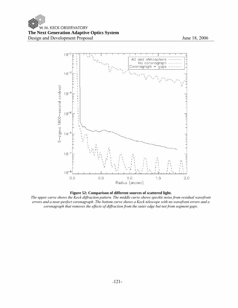
The Next Generation Adaptive Optics System Design and Development Proposal June 18, 2006
-121-
Figure 52: Comparison of different sources of scattered light.
The upper curve shows the Keck diffraction pattern. The middle curve shows speckle noise from residual wavefront errors and a near-perfect coronagraph. The bottom curve shows a Keck telescope with no wavefront errors and a
coronagraph that removes the effects of diffraction from the outer edge but not from segment gaps.

The Next Generation Adaptive Optics System Design and Development Proposal June 18, 2006
-122-
Figure 53: Comparison of the effects of static wavefront errors on NGAO high-contrast performance. Internal errors are simulated as non-common-path optical errors with a -2.5 power spectral density index.
Figure 54: Effects of residual segment aberrations on contrast.

The Next Generation Adaptive Optics System Design and Development Proposal June 18, 2006
-123-
4.3.2.8 Observing Efficiency and Up-Time
Requirements: • Observing Efficiency
o ≤ 20 min overhead per night o ≤ 120 sec between end of slew and ready for science exposure o ≤ 10 sec between start of nod command and ready for science exposure o ≤ 15 sec to reconfigure between J, H and K-bands o ≤ 120 sec to switch between LGS and NGS mode o ≤ 600 sec to switch between NGS and LGS mode (assuming daytime setup) o ≤ 120 sec to switch between AO science instruments (assuming daytime setup)
• Up-time o ≤ 5% of time lost to AO problems
We are not at the point in the design where these requirements can be evaluated. These are all reasonable requirements based on the existing Keck AO systems. 4.3.3 Point Design Subsystems
The NGAO system can be divided into the four main categories shown in Figure 55.
Figure 55 NGAO Major System Categories.
In the following sections we will discuss the major elements of each of these categories. More detail on the components and the status of current technology can be found in Appendix. Components and Component Technology. 4.3.3.1 AO System
The major elements of the AO system are shown in Figure 56.

The Next Generation Adaptive Optics System Design and Development Proposal June 18, 2006
-124-
Figure 56 Major AO Subsystems.
AO Enclosure and Opto-mechanics: The overall scheme has already been described in section 4.3.1. The specific design choices associated with the AO enclosure and opto-mechanics are tabulated in Appendix. AO System Key Features. Real-Time Control: The feasibility of the point design real-time architecture shown in Figure 45 can be determined by performing an analysis of the required processing steps (more details can be found in section 12.5. The symbols that are used in this calculation are first defined in Table 15 along with the values we have assumed for our analysis. Table 16 lists the steps performed on the image processors. For each step the algorithm, number of required processors and number of required clock cycles are listed. Table 17 provides the same analysis for the tomography unit and Table 18 for the DM projection and fitting.
Table 15 Definition of terms used in processing calculation. Symbol Meaning Value
N Number of subapertures across telescope 62 NGS Number of GS = wavefront sensors 5 NDM Number of deformable mirrors 11 NL Number of layers in model atmosphere 7 NP Number of pixels per read amplifier 3000 NS Number of pixels in a Hartmann subaperture
(total) 160
f Wavefront sensor sample rate (Hz) 1000

The Next Generation Adaptive Optics System Design and Development Proposal June 18, 2006
-125-
Table 16 Image Processor steps.
Processing step Algorithm Number of Processors
Number of Clock Cycles
1 Read data from camera Parallel readout from CCD
NP
2 Background subtract and Flat field multiply
Multiply-add N×N×NGS NS
3 Compute centroids Template multiply, sum, and scale result
N×N×NGS 1+NS + 1 (assumes 3 adders per processor)
4 Boundary slope conditioning Curl-free extension (Poyneer, 2002)
2πN×NGS 2πN
5 Fourier transform FPGA/DFT N×N×NGS 3N 6 Slope to phase Complex multiply-
add N×N×NGS 3
7 Pupil distortion correction Cubic spline N×N×NGS 16 8 Transfer data to tomography processor N
Table 17 Tomography Unit processing steps.
Processing step Algorithm Number of Processors
Number of Clock Cycles
1 Subtract estimate from data Add N×N×NGS 1 2 Precondition Complex Multiply N×N×NGS NGS 3 Inverse transform FPGA/DFT N×N×NGS 3N 4 Aperture mask Multiply N×N×NGS 1 5 Transform FPGA/DFT N×N×NGS 3N 6 Back propagate, interpolating LGS
cone beams Multiply accumulate, cubic spline
N×N×NL NL + 16
7 Post condition Multiply N×N×NL 1 8 Forward propagate, interpolating LGS
cone beams Sum, cubic spline N×N×NL NL + 16
9 Inverse transform FPGA/DFT N×N×NGS 3N 10 Aperture mask Multiply N×N×NGS 1 11 Transform FPGA/DFT N×N×NGS 3N Iterate steps 1-11 approximately 5
times per sample time step T to get a solution consistent with WFS measurements

The Next Generation Adaptive Optics System Design and Development Proposal June 18, 2006
-126-
Table 18 DM Projection and Fitting processing steps.
Processing step Algorithm Number of Processors
Number of Clock Cycles
1 Projection Multiply accumulate N×N×NL NL 2 Pupil distortion correction Cubic spline N×N×NDM 16 3 Deconvolution Complex multiply N×N×NDM 1 4 Inverse transform FPGA/DFT N×N×NDM 3N 5 Voltage lookup Lookup table N×N×NDM 2 Possibly 3 iterations of steps 3, 4,
and an aperture masking to suppress ringing at the edge of the aperture
The scaling laws used in the above three tables can be used to provide estimates of processor hardware requirements. Assuming the values given in Table 15 the following derived requirements were determined:
• Number of Processor Boards: 10 o The total number of independent processors for the 64x64 subaperture five LGS
system is 42,284. Each “processor” handles the calculations associated with one subaperture and either one wavefront sensor, one layer of atmosphere, or one deformable mirror. Estimates of usage of FPGA real estate indicate that 45 such processors can fit on a moderate size chip. Assuming a design with 100 chips per board this implies that roughly 10 boards are required.
• Clock Speed: 9MHz o The required control frame rate is 1 kHz and with 9000 clock cycles required per
frame sample time, the minimum clock speed is 9 MHz. • Power Consumption: 2kW
o Current FPGA chips consume power at a rate proportional to their usage. For example, a typical chip might consume 1 W at idle power plus 0.1 W per MHz clock speed assuming all the logic on the chip real-estate is being utilized. For the 9 MHz clock, and a total of 1000 chips, the total power is 2 kW.
Diagnostic Stream: The MPP architecture is amenable to real-time data-streaming to RAID disks for later post-processing and/or diagnosis at full frame rate. The data streaming I/O is established on a separate FPGA data bus so that telemetry overhead is almost transparent to the real-time control processing. Non-Real-Time Control: The current count of the devices requiring motion control indicates that 72 motion control stages are required to support the point design. This represents a rough doubling of the number of degrees of freedom on the existing Keck II LGS system (~ 40 stages).

The Next Generation Adaptive Optics System Design and Development Proposal June 18, 2006
-127-
4.3.3.2 Laser System
The major elements of the laser system are shown in Figure 57
Figure 57 Major Laser Subsystems.
Laser Enclosure: The point design assumes that the laser enclosure will be located on, or under, one of the Nasmyth platforms (similar to the approach being taken for the Keck I laser). This will likely need to be a clean room with humidity and temperature control as well as glycol cooling. Laser: The point design assumes three 50 W mode-locked CW lasers similar to the one that is currently being fabricated for Gemini-South (a 20 W version of this laser is being fabricated for the Keck I LGS AO system). A beam combination system will be required to provide 30 W per LGS. Beam Transport: Fiber transport using five to ten single mode fibers is currently assumed in the point design. This approach will be tested for the Keck I LGS AO system. A beam transport system using tracking mirrors is a viable backup approach. Laser Pointing, Uplink Tip-Tilt and Diagnostics: The output of the fibers must be appropriately formatted before insertion into the launch telescope. Part of this system will need to be a fast tip-tilt mirror to compensate for the fast tip-tilt motion measured on the LGS wavefront sensors (alternatively a mirror could be placed in front of the LGS wavefront sensors). Various diagnostic systems (cameras and/or power meters) will be required to ensure that the system is properly functioning and properly aligned. A quarter-wave plate will be required to convert the linearly polarized laser light to circular polarization. Launch Telescope: A 50 cm diameter launch telescope is assumed in the point design. Such a telescope will need to be produced for the Keck I LGS AO system.

The Next Generation Adaptive Optics System Design and Development Proposal June 18, 2006
-128-
Laser System Control: To the extent possible the non-real-time laser system control should be identical to that for the AO system. It is likely however that we will need to add an EPICS interface on top of a vendor supplied control system. A safety system will need to be implemented to protect the laser system and personnel. The existing Keck systems and procedures for aircraft, satellites and laser traffic control will need to be extended to the NGAO system. 4.3.3.3 Operations Tools
Figure 58 Major Operations Tools Categories.
The operations tools are the high-level user and automation tools that will be used to carry out science observations. The categories are roughly based on the existing LGS AO operations tools. The categories shown in Figure 58 can be briefly described as follows:
• The observing setup tools are used to calibrate and setup the AO system for nighttime (and daytime) operations.
• The user interfaces are those provided for the AO operator and the astronomer. • A number of tools are needed to allow the astronomer to plan their observations. • All observations are ideally performed from the science instrument user interface.
Automatic handshaking and information exchange needs to be performed between the science instrument, AO system and the telescope control systems.
The Next Generation Adaptive Optics System Design and Development Proposal June 18, 2006
-129-
• A number of tools will be need to monitor the performance of the AO and laser systems, in particular to allow the astronomer and operator to know if the AO system is operating at the appropriate level for the existing atmospheric conditions.
• The automation and optimization tools automatically configure and optimize the system and its performance.
• The user documentation provides operational information needed by the astronomer, AO support astronomer and AO operator. This documentation would include procedures for system checkout, operations and troubleshooting, as well as a history of recent calibration parameters and system performance.
4.3.3.4 Science Instruments
The philosophy for the NGAO instrument compliment is to address the large parameter space offered by NGAO with primarily simple, specialized instruments. By separating wavelength ranges along natural breakpoints based on optical and thermal design considerations and by providing spectroscopy with integral field units (IFUs) we can meet the science needs without requiring complex multimode instruments. The one exception is a deployable near-IR IFU spectrometer that is of necessity a more complex instrument with a greater number of operating modes. The proposed instrument compliment for NGAO is as follows:
Imaging: • Visible imager • Near-IR imager • Thermal near-IR imager
Spectroscopy:
• Near IR IFU • Visible IFU • Deployable near IR IFU
Instruments are designed for Nasmyth platform operation with a single axis of rotation. The current arrangement of the AO system optical “switchyard” will support upward or downward looking instruments and this may be attractive to simplify the instrument design and flexure requirements. Downward looking instruments will be more difficult to access and it appears that the envelope sizes and allowable weights will be more limited as well. Downward looking configurations appear most suited to the imaging instruments, all of which are relatively simple and of modest size. All of the instruments are based on currently available detector technology with some instruments taking advantage of anticipated evolutionary developments of current detector technology that we believe will become available within the ~5 year timeframe of NGAO development.
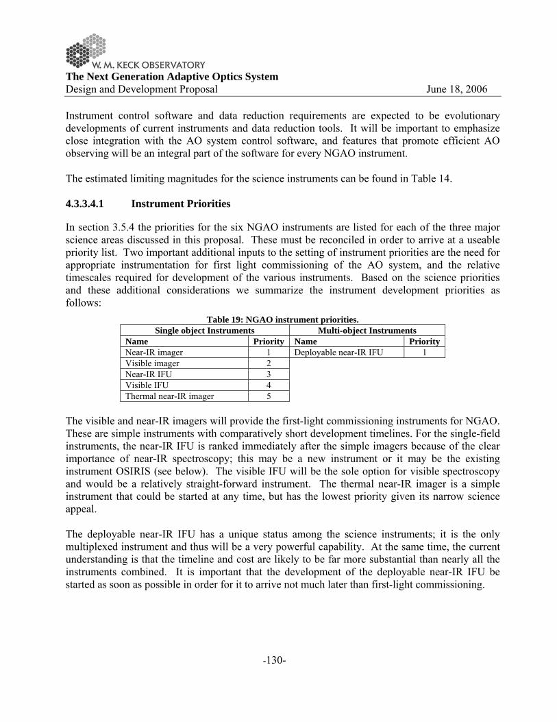
The Next Generation Adaptive Optics System Design and Development Proposal June 18, 2006
-130-
Instrument control software and data reduction requirements are expected to be evolutionary developments of current instruments and data reduction tools. It will be important to emphasize close integration with the AO system control software, and features that promote efficient AO observing will be an integral part of the software for every NGAO instrument. The estimated limiting magnitudes for the science instruments can be found in Table 14. 4.3.3.4.1 Instrument Priorities
In section 3.5.4 the priorities for the six NGAO instruments are listed for each of the three major science areas discussed in this proposal. These must be reconciled in order to arrive at a useable priority list. Two important additional inputs to the setting of instrument priorities are the need for appropriate instrumentation for first light commissioning of the AO system, and the relative timescales required for development of the various instruments. Based on the science priorities and these additional considerations we summarize the instrument development priorities as follows:
Table 19: NGAO instrument priorities. Single object Instruments Multi-object Instruments
Name Priority Name Priority Near-IR imager 1 Deployable near-IR IFU 1 Visible imager 2 Near-IR IFU 3 Visible IFU 4 Thermal near-IR imager 5
The visible and near-IR imagers will provide the first-light commissioning instruments for NGAO. These are simple instruments with comparatively short development timelines. For the single-field instruments, the near-IR IFU is ranked immediately after the simple imagers because of the clear importance of near-IR spectroscopy; this may be a new instrument or it may be the existing instrument OSIRIS (see below). The visible IFU will be the sole option for visible spectroscopy and would be a relatively straight-forward instrument. The thermal near-IR imager is a simple instrument that could be started at any time, but has the lowest priority given its narrow science appeal. The deployable near-IR IFU has a unique status among the science instruments; it is the only multiplexed instrument and thus will be a very powerful capability. At the same time, the current understanding is that the timeline and cost are likely to be far more substantial than nearly all the instruments combined. It is important that the development of the deployable near-IR IFU be started as soon as possible in order for it to arrive not much later than first-light commissioning.

The Next Generation Adaptive Optics System Design and Development Proposal June 18, 2006
-131-
4.3.3.4.2 Reuse of Existing Instruments
We have considered the possibility of using both NIRC-2 and OSIRIS with the NGAO system. However, we are concerned that this may offer limited benefits and in fact may complicate the AO system design or lead to performance compromises. Neither instrument was designed to be rotated about its optical axis, making it necessary to include a K-mirror or other image derotator in the NGAO system. Although a K-mirror is included in the NGAO point design described in section 4.3, it will add to the emissivity of the system and reduce the throughput. The space required for the K-mirror will also complicate the layout of the AO relay. For NIRC-2 we have considered the feasibility of improving on the ~110 nm of wavefront error contributed by the instrument and concluded that no practical redesign of the existing three camera scales would significantly reduce this value. Given that the NGAO system demands instrument wavefront error contributions on the order of 25 nm, we have concluded that NIRC-2 is not a good choice for use with the NGAO system. Finally, NIRC-2 is equipped with only a 1K x 1K detector and obsolete control and readout electronics. When the costs of the upgrades to NIRC-2 are compared with the cost of new, better performing near-IR and thermal near-IR imagers it does not seem logical to re-deploy NIRC-2 with the NGAO system. OSIRIS is better suited to the NGAO system, but it is not compatible with a rotator. It is also currently planned for OSIRIS to move to the Keck I AO system when installation and commissioning of the new guide star laser is completed. During the time the NGAO system is being commissioned on Keck II telescope we anticipate that there will be significant demand for Keck I LGS AO making it impractical to move OSIRIS back to the Keck II telescope for use with NGAO. Discussions should be undertaken to determine if using OSIRIS with NGAO is desirable, and if so then perhaps NIRC-2 should be moved to the Keck I telescope for use with the LGS AO system instead of OSIRIS. 4.3.3.4.3 Imaging
For imaging we have identified three simple imagers. A visible imager covering 0.6 to 1.1 µm, a near-IR imager covering 1.1 to 2.5 µm equipped with a high performance coronagraph, and a mid-IR imager covering 3 to 5.3 µm. By deliberately dividing the infrared wavelength ranges into near-IR and thermal near-IR segments we simplify the requirements for achromaticity in the instrument optics, improving the image quality and lowering the cost and implementation risks. All of the imagers are designed to provide Nyquist sampled diffraction-limited images at their respective short wavelength cutoffs. It should be noted that the exact boundary between the visible imager and the near-IR imager is probably best established by the actual QE curves of the

The Next Generation Adaptive Optics System Design and Development Proposal June 18, 2006
-132-
detectors used for these imagers, and the actual values for the boundary may lie between 0.9 and 1.1 µm and even have some overlap. High contrast imaging is a significant component of the science for NGAO and it will be important to maximize the dynamic range of each detector system. Techniques such as non-destructive or region of interest readout permitting variable integration times across the detector may be required to meet the needs of high contrast imaging in an efficient manner. 4.3.3.4.3.1 Visible Imager
For the short wavelength cutoff of 0.6 µm Nyquist sampling at the diffraction limit requires ~6 mas pixels. While it is tempting to make a visible camera that covers the entire corrected field of the NGAO system (~40”), the majority of the science cases require modest FOVs, typically 3”. With the appropriate focal reducer a single deep depletion 4K x 4K CCD with 10 µm pixels will provide a FOV of approximately 20” x 20” with a 6 mas plate scale. The focal reducer would operate at f/41. The basic requirements for the visible imager are summarized in Table 20.
Wavelength coverage FOV Imaging (µm) Sampling
0.6 to 1.1 20” x 20” Nyquist (6 mas)
Table 20: Basic Requirements for the Visible Imager The imager should be equipped with a filter wheel offering the appropriate standard photometric passbands and should also provide a polarimetric mode with ~1% accuracy. 4.3.3.4.3.2 Near-IR Imager
Diffraction limited sampling of 10 mas will result in a FOV of approximately 20” x 20” for a 2K x 2K detector. This meets the requirements of the majority of the science cases with the exception of observations of the protostar circumstellar disks. Based on a Hawaii-2RG detector or equivalent, the basic requirements of the near-IR imager are summarized in Table 21.
Wavelength coverage FOV Imaging (µm) Sampling
1.0 to 2.45 20” x 20” Nyquist (10 mas)
Table 21: Basic Requirements for the Near-IR Imager At a minimum the imager should be equipped with broadband filters suitable for imaging. Specialized narrowband filters may also be required for some coronagraphic imaging applications.

The Next Generation Adaptive Optics System Design and Development Proposal June 18, 2006
-133-
The design of the instrument should be optimized for high contrast operation with the coronagraph (companion delta magnitude sensitivities of 10 in K-band with 0.5” separations). It is also desirable that the near-IR imager offer a polarimetric mode with ~0.5% accuracy. 4.3.3.4.3.3 Thermal near-IR Imager
The lower backgrounds expected with the NGAO system should make practical a thermal near-IR imager for L and M-bands. The selection of detectors offering state of the art performance in these longer wavelength ranges is more limited, and currently these are offered in a maximum size of 1K x 1K. Based on diffraction limited sampling of 25 mas the resulting FOV is approximately 25” x 25” which is close to the <30” requirement of the protostars case and more than adequate for the other cases requiring mid-IR imaging. The basic requirements for the thermal near-IR imager are summarized in Table 22.
Wavelength coverage (µm)
FOV Imaging Sampling
3 to 5.3 25” x 25” Nyquist (25 mas)
Table 22: Basic Requirements for the Thermal near-IR Imager The instrument will require a modest filter wheel and may benefit from selectable cold stops. 4.3.3.4.4 Spectroscopy
For spectroscopy we believe that the best choice is spatially sampled or integral field spectroscopy. The high spatial resolution of the NGAO system will result in a sensitivity gain that will reduce the significance of the loss in efficiency experienced with IFUs in comparison to single slit spectrographs. Being able to simultaneously sample the spectra at many points on an object enables a number of important diagnostics and allows the efficient characterization of radial velocities. We have identified a requirement for three IFU instruments for the NGAO system, an “OSIRIS like” near-IR IFU with a single sampling field, a visible wavelength IFU with a single sampling field and a deployable near-IR IFU with a modest number of sampling fields. Not all of the science requirements for visible spectroscopy require an IFU, but it does appear possible to meet all of the visible spectroscopy requirements with an IFU as long as the instrumental throughput is high enough to allow the required faint magnitude limits to be achieved with reasonable exposure times.

The Next Generation Adaptive Optics System Design and Development Proposal June 18, 2006
-134-
4.3.3.4.4.1 Near-IR IFU
The near-IR IFU will be an on axis instrument based on the general configuration of OSIRIS. The key differences are a larger field of view and requirements for lower backgrounds. By using a 4K x 4K detector, either a mosaic of 4 Hawaii-2RG detectors or a single Hawaii-4RG detector (under development) the broadband mode will offer 80 x 50 spatial samples with 2000 samples per spectra. In narrow band mode with 1000 samples per spectra the spatial sampling will consist of 160 x 50 spatial samples. The notional requirements for a near-IR IFU are summarized Table 23.
Sampling Wavelength
coverage (µm)
FOV Spatial (IFU, mas)
Spectral (pixels/spectra)
Resolution
1.0 to 2.45 ~4,000 8” x 5” 80 x 50,
100 ~2,000
(broad band)
16” x 5” 160 x 50, 100
~1,000 (narrow band)
4” x 2.5” 80 x 50, 50
~2,000 (broad band)
8” x 2.5” 160 x 50, 50
~1,000 (narrow band)
2” x 1.25” 80 x 50, 20
~2,000 (broad band)
4” x 1.25” 16 x 50, 20
~1,000 (narrow band)
Table 23: Notional requirements for the near-IR IFU Mechanisms will be required for scale selection, filter selection and masking of the lenslet or slicer output for the broadband modes. 4.3.3.4.4.2 Visible IFU
The visible IFU will be an on axis instrument with some similarities to OSIRIS. Although many configurations are possible, we have identified a mirror slicer based arrangement that meets the requirements of the science case using a single 4K x 4K detector. With a format of 3600 spectra along the 4K dimension the resulting IFU format is 60 x 68 samples for broadband spectra with 2000 samples per spectrum, and 120 x 68 samples for narrowband spectra with 1000 samples per spectrum. At the 100 mas spatial sampling the resulting broadband FOV is 6” x 6.8” and 12” x 6.8” for narrowband. Additional plate scales of 50 and 20 mas (or similar) may also be provided. The range of sampling scales provided by the visible IFU meets or exceeds all of the science case requirements. A range of spectral resolutions are stated in the science requirements, and with one

The Next Generation Adaptive Optics System Design and Development Proposal June 18, 2006
-135-
exception these can all be met with R ~3,000. There is one case for the measurement of outflow velocities in protostar circumstellar environments with a requirement for R ~20,000. While a higher resolution mode might be provided in the IFU, the complication of a moving grating and the limited spatial sampling imposed by the much higher spectral resolution may make this impractical. Mechanisms will be required for scale selection, filter selection and masking of the slicer output for the broadband modes. The notional requirements for a visible IFU are summarized Table 24.
Sampling Wavelength
coverage (µm)
FOV Spatial (IFU, mas)
Spectral (pixels/spectra)
Resolution
0.6 to 1.1 ~3,000 6” x 6.8” 60 x 68,
100 ~2,000
(broad band)
12” x 6.8” 120 x 68, 100
~1,000 (narrow band)
3” x 3.4” 60 x 68, 50
~2,000 (broad band)
6” x 3.4” 120 x 68, 50
~1,000 (narrow band)
1.2” x 1.36” 60 x 68, 20
~2,000 (broad band)
2.4” x 1.36” 120 x 68, 20
~1,000 (narrow band)
Table 24: Notional requirements for the Visible IFU A significant reduction in complexity compared to OSIRIS results from ambient temperature operation of the entire optical train. While a more innovative design than a simple mirror slicer may be possible, several instruments using high performance slicers are currently being designed so building on this work will provide important risk reduction benefits. 4.3.3.4.4.3 Deployable Near-IR IFU
The deployable near-IR IFU is the only instrument proposed for NGAO that has significant complexity. We propose the use of MOAO with high order AO correction using a MEMs deformable mirror incorporated in each IFU unit. The field of regard (FOR) for the deployable IFU is modest, approximately 1.5’ x 1.5’. At this point we believe a multiplex of 6 will meet the requirements of the science cases. A 2K x 2K detector will allow a maximum format of 30 x 34 samples with 2000 samples per spectrum. Each IFU unit would have a fixed sampling of 100 mas, and a spectral resolution of

The Next Generation Adaptive Optics System Design and Development Proposal June 18, 2006
-136-
approximately R=4,000 for processing of spectra to suppress the OH lines. Each IFU requires a filter wheel containing order-sorting filters for the near-IR bands. The notional requirements for each deployable IFU are shown in Table 25.
Spectroscopy Sampling Wavelength
coverage (µm)
FOV Spatial (IFU, mas)
Spectral (pixels/spectra) Resolution
1.0 to 2.45 3” x 3.4” 30 x 34, 100
~2,000
~4,000
Table 25: Notional requirements for each unit of the near-IR deployable IFU. Object selection can be accomplished using probe arms or perhaps a tiled focal plane configuration. Provisions for AO performance monitoring including a “truth” wavefront sensor may also be required. 4.3.3.4.5 Interferometry
The Keck Interferometer and participation in the ‘OHANA Interferometer require AO systems on both Keck telescopes. How and if the NGAO system can be made compatible with the Interferometer requirements will be evaluated during the system design phase. Modifications to the Interferometer beam train will also be considered. 4.4 System Design Technical Approach
In this section we discuss the engineering questions that need to be answered in the System Design phase and how we intend to approach the iterative process of requirements and system design development. In terms of functionality, performance, cost and complexity, NGAO will be one of the most sophisticated AO systems attempted to date. Such a system requires careful planning and attention to requirements at the earliest stages of its design. In this regard the technical team for NGAO will continue to work closely with the science teams during the system design phase to ensure that NGAO is as scientifically productive as possible. The technical team will follow the standard system design approach for new Keck instruments. This approach features the development of top-level system requirements to satisfy science “test cases”. These science cases are the basis for establishing NGAO function and performance. A concept of operations will be developed to determine features necessary for NGAO including observing modes, calibrations methods and data processing. The system requirements must also consider the full lifecycle of the NGAO system including installation and operations. A series of trade studies will follow the requirements development leading to the NGAO architecture. This

The Next Generation Adaptive Optics System Design and Development Proposal June 18, 2006
-137-
architecture will be evaluated for performance, cost and risk. The results of this evaluation will be used to revise the system requirements. Subsequent NGAO architectures will be developed and reevaluated. To facilitate the evaluation of the NGAO system the technical teams will continue to develop and maintain the performance budgets discussed in section 4.3.2. The technical teams will work in the early phases of system design on validating their analytical models and computer simulations that feed into these performance budgets. Technical team members will also strive to crosscheck each other’s models and analysis. The technical team members will document their work as a set of electronic documents easily available to other team members. The science team members will determine a set of prototype science cases for each performance budget. The same science case would not necessarily be judged as key for all performance budgets. The prototype science cases would be similar to the science cases in Table 13. If the NGAO project is to make progress in the early phases of system design the technical team must be able to rapidly evaluate the performance of proposed NGAO architectures and receive feedback from the science teams. We proposed that a NGAO project scientist be appointed to coordinate with the NGAO PI on the science requirements and use case testing of any NGAO architecture. An integrated effort between engineers and astronomers is necessary for a successful NGAO design. To be truly useful the performance budget will require input and supporting analysis from the science teams. Our teams will build on the relationships already in place between the science teams and technical team from the production of this proposal. As the highest-level NGAO requirements begin to solidify the technical team will determine the system and subsystem level requirements for NGAO. These requirements will be used to guide the development of the NGAO architecture to the subsystem level. This architecture will include conceptual designs for all major systems to a sufficient level of detail to allow a cost estimate and a risk evaluation. These subsystems would be the same as discussed in the Point Design subsystems, although the exact details of the design could be radically different. As part of this proposal the technical team has identified a series of trade studies that will need to be performed to support the development of the NGAO system (See Appendix: System Design Phase Trade Studies). This list will be the starting point for our trade studies in the System Design phase of this project. The following is an abbreviated listing of some of the highest priority trades studies that have been identified:
• Consider the feasibility of upgrading one of the existing Keck AO systems to meet NGAO requirements.
• Determine best way to support Keck interferometer operations when NGAO is operational.

The Next Generation Adaptive Optics System Design and Development Proposal June 18, 2006
-138-
• Evaluate the performance impact of Rayleigh scatter on NGAO performance and consider various mitigation methods such as a pulsed laser.
• Determine the relative cost versus benefits of alternate optical relay designs. • Consider the cost/benefits of an adaptive secondary mirror implementation. • Consider the cost/benefits of a stand-alone tip/tilt mirror as opposed to mounting
another necessary optic on the tip/tilt stage. • Consider cost/benefits of different options for achieving the NGAO science goals in
the K through M-bands. In addition to a design concept for NGAO the technical team will manage the interface control between NGAO and its subsystems, primarily through interface control documents.

The Next Generation Adaptive Optics System Design and Development Proposal June 18, 2006
-139-
5 MANAGEMENT
5.1 Introduction
We have received the following guidance from Observatory management:
“The current management structure will continue for the initial System Design phase. Wizinowich (CARA) will continue to coordinate efforts in conjunction with Max and Liu of the AOWG, and with the continued active participation of staff from Caltech (Dekany), UC (Gavel) and CARA (Neyman, Adkins). This structure is expected to evolve in discussion over the next several months, as the System Design phase gets underway. The management structure for the longer term will be a product of the System Design, the next funded phase of the project. The eventual structure will be determined by the Observatory Directors/Deputy Director (Armandroff, Lewis, Bolte and Kulkarni) in consultation with key players. It is envisaged that staff from both the Observatory and its partner institutions will play leadership roles in the management of the NGAO program. These roles will include those of principal investigator, project manager, project scientist and system architect.”
Given the above statements the proposal team has focused on providing an overall draft definition of the project plan and schedule (section 5.2), on defining the work that needs to happen to successfully complete the SD phase (section 5.3), and on providing a risk assessment and management plan (section 5.4). 5.2 Project Plan and Schedule
A top-level work breakdown structure (WBS) is shown in Figure 59. This WBS assumes a single delivery of the NGAO system. If the NGAO project consists of multiple deliveries (i.e., a narrow field initial delivery followed by a wider field upgrade) then additional WBS elements could be required.

The Next Generation Adaptive Optics System Design and Development Proposal June 18, 2006
-140-
Figure 59 Top-Level WBS
All of the design work, and work in support of funding proposals, happens within WBS 1.0. Each design phase therefore consists of technical and management design work related to WBS 2.0 to 8.0. A product of the design phase will be a set of modeling and analysis tools (WBS1.5). These tools will be used during the development phase to help with the inevitable system engineering trades that will be required. The requirements (WBS1.6) and performance budgets (WBS1.7) will be maintained and appropriately updated as a result of these trades. The division of the NGAO system into the three major WBS elements of AO system (WBS2.0), laser system (WBS3.0) and operations tools (WBS4.0) has already been discussed in section 4.3.3. The AO and laser system WBS elements also include a lab I&T phase and a system acceptance task. These lab I&T phases will include integration and testing with the operations tools (WBS4.0) as much as possible. A WBS element (5.0) has been included for the science instruments. Modifications to existing science instruments may be covered at some level within this management structure. However, we

The Next Generation Adaptive Optics System Design and Development Proposal June 18, 2006
-141-
are intending that the construction of new instruments, or major modifications, would be managed through the Observatory’s instrument project management structure. The telescope integration and test WBS element (6.0) includes all the steps required to move the systems to the telescope and commission an operational science instrument. A separate WBS element (7.0) has been defined for the transition of the NGAO system from the development team to the operations group. It will be important for operational personnel to be involved in various aspects of the development effort in order for this project to benefit from their experience, for them to ensure that their needs are being made and for the expertise to be appropriately transitioned to the operations group. Operations personnel will in particular need to be involved during the design phase, to periodically check in during the system development phase and to be significantly involved in the operations tools and telescope I&T phase. The overall program schedule, organized by WBS, is shown in Figure 60. This plan shows the best case scenario where funding is available as needed, the team is able to ramp up to the required levels as needed and long lead procurement orders are placed to not cause schedule delays. This initial plan shows the design period beginning after the June, 2006 SSC meeting and ending, optimistically, in mid FY09. This is followed by two years of subsystem development and one year of telescope integration and test. Even with this optimistic schedule the first shared-risk science would not begin until late FY12. It is likely, given this optimistic schedule that any delays in ramping up this program will result in equivalent delays in the start of NGAO science. A more detailed schedule will be produced during the system design phase and as the management structure is defined.
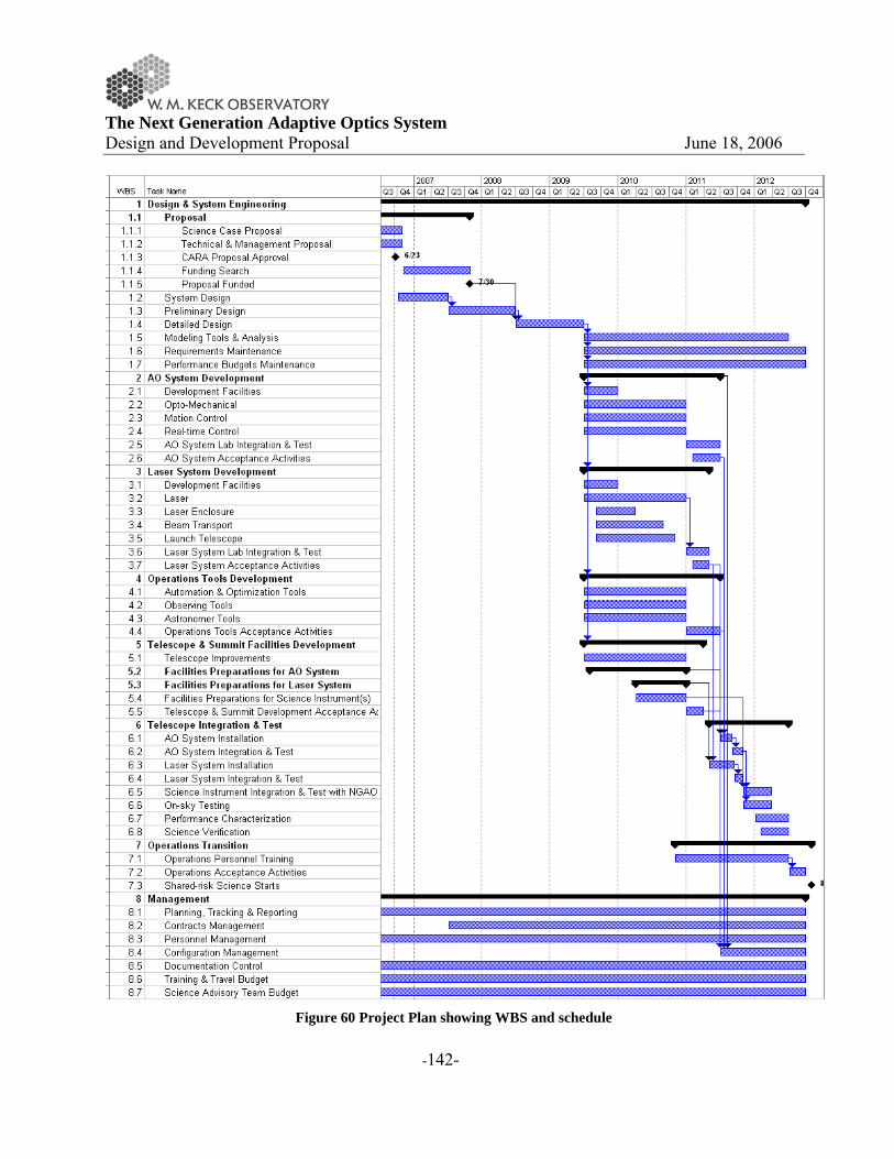
The Next Generation Adaptive Optics System Design and Development Proposal June 18, 2006
-142-
Figure 60 Project Plan showing WBS and schedule

The Next Generation Adaptive Optics System Design and Development Proposal June 18, 2006
-143-
5.3 System Design
The system design phase is the initial design phase for projects managed by WMKO. This phase proceeds the preliminary design phase. The system design includes a conceptual design plus a significant emphasis on how the overall project will be managed using a system engineering approach. 5.3.1 System Design Deliverables
WMKO provides the following standard guidance for the system design (SD) phase of a development project (Adkins, 2005):
“The principle objective of a system design is to establish a design approach that meets the scientific and user requirements established for the system. System design will establish a discipline integrated engineering plan for the proposed design, understand the technical risks, explore trade-offs, and determine estimates for performance and cost to completion.
The key deliverables from the system design phase are a Systems Requirements Document, a Systems Engineering Management Plan, a System Design Manual and a System Design Report.”
The SD phase of this project will deliver the four documents listed above. The Systems Requirements Document will include:
• A description of the science requirements • A description of the additional Observatory requirements • A description of the technical requirements organized by engineering discipline with a
clear flow down from the above requirements The System Design Manual will include the following components:
• Definitions of the functional requirements. • Descriptions of the design approach for major subsystems. • A summary of technology drivers and the associated research needs. • Performance budgets and error budgets. • A technical risk analysis.
The Systems Engineering Management Plan (SEMP) document will include the following components:
• A description of the project objectives and major milestones. • A description of the project organization. • A description of the project management process.

The Next Generation Adaptive Optics System Design and Development Proposal June 18, 2006
-144-
• A description of the project decision process and major decision points. • A risk assessment and a risk management plan. • Configuration management plans for hardware, software and documentation.
The System Design Report provides a high level summary of the work done during the SD phase and makes a proposal for the preliminary design phase of the project including a plan for the remainder of the project. This will be developed following a planning sequence based on the system level requirements, and proceeding from a WBS to task identification and description, schedule and budget development and finally a Microsoft Project plan.. 5.3.2 System Design Plan
A proposed schedule for the SD phase is shown in Figure 61. This plan is focused on the production of the documents defined in the previous section. The system requirements document is produced under WBS element 1.2, the SD manual under WBS 1.3, the system engineering manual plan under WBS 1.4, and the summary SD report under WBS 1.1. Management of the SD phase occurs in WBS 1.1. A work estimate (~ 18000 hours) has been included in Figure 61 (see section 6.1 for additional discussion). Note that this estimate includes the effort to perform the ~ 3000 hours of trade studies listed in Appendix: System Design Phase Trade Studies; most of these trade studies are covered under WBS1.3.2 and 1.3.4. This estimate has been prepared independent of where the work will be performed or by whom. The reasons for this are twofold: The first is that the Directors have indicated their intention to determine the management structure and participants after this proposal is reviewed. The second is that the current Observatory’s FY07 plan assigns both personnel and dollars to the NGAO project. The feasibility of achieving this plan will depend on the availability of personnel (and budget) to perform the required tasks and thus depends on how the work is to be distributed among the potential participants at WMKO, Caltech, UC and elsewhere. To the extent possible we intend to continue the successful collaborations developed during the proposal phase in order to draw upon the expertise and energy of the Keck community.

The Next Generation Adaptive Optics System Design and Development Proposal June 18, 2006
-145-
Figure 61 System Design Phase Plan showing WBS and Schedule

The Next Generation Adaptive Optics System Design and Development Proposal June 18, 2006
-146-
Here are some recommendations for the system design phase management and task distribution. These recommendations are organized by the WBS element categories in Figure 61:
• WBS1.1 Management and WBS 1.4 System Engineering Management Plan o WMKO should continue to manage the overall SD phase effort o Peter Wizinowich should play the lead management role. o Sean Adkins should manage the system design phase for the science instruments. o A science advisory committee should be identified to provide high level guidance to
the NGAO project. • WBS1.2 System Requirements
o Science Requirements A NGAO project scientist needs to be identified in order to ensure the
scientific success of this project. Claire Max has volunteered for this role and she would bring the required experience and enthusiasm to this role.
The NGAO project scientist and science team should continue to lead the development and iteration (as the design evolves) of the science requirements.
Some funds need to be budgeted to support the additional science team work required for the system design. We have proposed the equivalent of three years of graduate student effort and one year of a postdoc in our effort estimates.
o Observatory Requirements and Requirements flow down Managed and documented by WMKO.
• WBS1.3 System Design o This is the area, especially the design approach and performance budgets
categories, where we need to take advantage of the expertise and resources at Caltech, UC and WMKO. We need to determine where the various trade studies, risk reduction efforts, performance analyses, cost estimates, etc. would be best performed. The Caltech and UC teams (represented by Rich Dekany and Don Gavel, respectively) have indicated their interest in supporting this effort.
5.4 Risk Assessment and Risk Management Plan
A detailed initial risk assessment spreadsheet can be found in Appendix. Risk Assessment and Mitigation Plans. This spreadsheet contains a list of ~40 risk items identified during the initial development of the point design. The severity and probability of each item is indicated, along with the risk mitigation plan. During the system design each of these risk areas will be further addressed either as part of the planned trade studies and/or as part of the risk assessment.

The Next Generation Adaptive Optics System Design and Development Proposal June 18, 2006
-147-
6 BUDGET
The following sections provide budget estimates for the system design phase and the remaining design and development costs through facility class operation of the NGAO system, as well as budget estimates for science instruments and operations. The total budget to design and implement the NGAO facility, from system design phase through the start of facility class operation is estimated to be $35M ± $10M. The total budget to design and implement the first round of the three key science instruments (near-IR and visible imagers plus a near-IR deployable IFU), recommended to take full advantage of the NGAO system, is estimated to be $20M ± $4M. The system design phase costs are estimated to be ~$980k. This is about $390k larger than the amount in the Observatory’s current FY07 budget. On the other hand this only represents about 3% of the total NGAO budget estimate (without consideration of the science instruments). 6.1 System Design Phase
The system design phase shown in Figure 61 includes a preliminary effort estimate of 17,900 hours. A total of 5,500 of these hours correspond to graduate students and one postdoc, and the remainder represents 6.4 FTEs (assuming the WMKO standard of 1940 hours per FTE). The cost of these FTEs will depend on the individuals and the institutions where this work is performed. It may be reasonable to assume that Caltech, UC and WMKO will not add overheads since these funds are toward the construction of new instrument capabilities. A preliminary labor cost estimate is $920k using the following assumptions: the WMKO FY07 engineering labor rate of $120k/FTE, $90k for three graduate students and $60k for one postdoc. In addition to the labor costs some travel funds will be required primarily to facilitate collaboration between the science and technical teams ($40k). A small budget will be retained for miscellaneous procurement costs ($20k). The total of $980k represents 3% of the overall NGAO AO budget (excluding science instruments) discussed in the next section. It is interesting to compare this to some general rules of thumb. One is that about 10% of the total instrument development cost is typically incurred in generating a reliable cost estimate. Another is that 20-25% of the total costs should be spent in the design phase (note that there are still two design phases after the system design phase). Based on these comparisons it seems that our current system design budget estimate may be low. However, we believe that we have properly identified the path forward and have a clear idea of how to proceed. A more detailed estimate will be prepared as individuals and the next level of tasks are added to the project plan.

The Next Generation Adaptive Optics System Design and Development Proposal June 18, 2006
-148-
If the existing $590k WMKO FY07 budget for NGAO represents a cost cap then we either need to extend the system design phase into FY08, reduce our expectations for the system design phase or leverage additional contributions. 6.2 Preliminary and Detailed Design through Full Scale Development
We are not at the point where a reliable estimate can be made of the cost to implement the NGAO facility. However, we can provide some reference numbers and discuss the major cost drivers. Gemini-South (GS) has two comparable, but still more modest, AO systems that can be used for budget reference purposes. The GS MCAO system is budgeted in 2003 dollars to cost $18M, including $3.6M for the 50 W laser and excluding any science instruments (M. Sheehan, private communication). The Gemini Planet Imager (GPI) is budgeted in 2006 dollars at $19M, with Gemini holding $6M in reserve; this includes the science instrument and no laser is required for this system. The major cost change between the GS MCAO and the Keck NGAO systems is the need for two additional 50W lasers. If we use the GS MCAO budget as a basis for estimation then we would need to add $7M for two additional lasers. This corresponds to a total of $29M in 2007 dollars, assuming 4% inflation. The TMT first light NFIRAOS instrument (goal of 170 nm rms wavefront error) recently completed its conceptual design review. The budgeted numbers are $25M for the AO system and $24M for the LGS facility. NGAO should be simpler and therefore less expensive than NFIRAOS in a number of ways including: smaller physical size, fewer actuators and subapertures, less flexibility in the LGS asterism geometries and only cooling to -15°C instead of -38°C. If NFIRAOS were used as a cost basis then the NGAO costs might be extrapolated to be closer to $40M. A very rough initial budget estimate to implement the NGAO point design, excluding science instruments, is provided in Table 26. This was produced in a bottoms-up approach by using the list of required items in the point design spreadsheet (Appendix. AO System Key Features shows one of the sheets from this spreadsheet) and providing a first guess at the associated procurement costs and required labor (based on experience with the Keck AO systems). The total in this estimate approach is $21M in procurements and 41 FTEs, before adding contingency. The FTEs were converted to dollars using the CARA engineer rate of $120k/year. The actual personnel dollars and the ratio of procurements to personnel dollars would of course depend on where the work is performed. No overhead is assumed in this initial estimate. The bottom line is $27M, including $1M in spares for the operational system. A 25% contingency has been added to raise the total to $34M.

The Next Generation Adaptive Optics System Design and Development Proposal June 18, 2006
-149-
Based on the above scaling and our very rough initial estimate it seems reasonable to think of a cost of roughly $35M ± $10M as being associated with the NGAO system point design. A much more rigorous budget estimate will be prepared for each phase of the NGAO design process, beginning with the system design phase.
Table 26 Very Rough Initial Budget Estimate (07 dollars) for Preliminary Design through Commissioning.
WBS Subsystem Procure
($k) Design (FTE)
Implement (FTE)
FTE ($k)
Total ($k)
1 Design & Sys Eng 50 11.9 2.5 1727 1777 2 AO System 7207 19.0 2280 9487 3 Laser System 12233 3.2 388 12621 4 Operations tools 0 6.7 800 800 6 Telescope I&T 50 5.0 600 650 7 Ops Transition 0 1.0 120 120 8 Management 600 1.2 3.7 592 1192 Ops Spares (5%) 972 0 972 Contingency (25%) 5035 3 10 1627 6662 Total = 26147 16 51 8134 34281
6.3 Science Instruments
Estimates for the science instruments are given in Table 27. These estimates are based on a combination of experienced ROM estimating and comparison with other similar instruments that have been recently developed. At this stage the estimates should be considered uncertain by at least 20%. The instruments are listed in approximate priority order. The first three instruments in this list are particularly critical to the success of the science cases discussed in this proposal. Reuse of the existing OSIRIS (at a more modest cost), or use of one of the deployable near-IR IFU units, are options to building a near-IR IFU. There could be some expense as well for modifications in support of the interferometer.
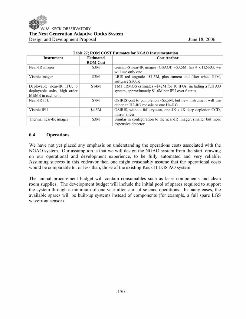
The Next Generation Adaptive Optics System Design and Development Proposal June 18, 2006
-150-
Table 27; ROM COST Estimates for NGAO Instrumentation Instrument Estimated
ROM Cost Cost Anchor
Near-IR imager $3M Gemini-S near-IR imager (GSAOI) ~$3.5M, has 4 x H2-RG, we will use only one
Visible imager $3M LRIS red upgrade ~$1.5M, plus camera and filter wheel $1M, software $500K
Deployable near-IR IFU, 6 deployable units, high order MEMS in each unit
$14M TMT IRMOS estimates ~$42M for 10 IFUs, including a full AO system, approximately $1.6M per IFU over 6 units
Near-IR IFU $7M OSIRIS cost to completion ~$5.5M, but new instrument will use either an H2-RG mosaic or one H4-RG
Visible IFU $4.5M OSIRIS, without full cryostat, one 4K x 4K deep depletion CCD, mirror slicer
Thermal near-IR imager $3M Similar in configuration to the near-IR imager, smaller but more expensive detector
6.4 Operations
We have not yet placed any emphasis on understanding the operations costs associated with the NGAO system. Our assumption is that we will design the NGAO system from the start, drawing on our operational and development experience, to be fully automated and very reliable. Assuming success in this endeavor then one might reasonably assume that the operational costs would be comparable to, or less than, those of the existing Keck II LGS AO system. The annual procurement budget will contain consumables such as laser components and clean room supplies. The development budget will include the initial pool of spares required to support the system through a minimum of one year after start of science operations. In many cases, the available spares will be built-up systems instead of components (for example, a full spare LGS wavefront sensor).

The Next Generation Adaptive Optics System Design and Development Proposal June 18, 2006
-151-
7 APPENDIX. THE GLOBAL LANDSCAPE FOR NEXT GENERATION AO SYSTEMS
Table 28 Instruments for use with AO systems
Telescope GS Instruments Capabilities Dates PhaseCFHT NGS KIR & GriF with Pueo 19-element curvature 1996- Operation
CFHT LGS Visible All Sky AO (VASAO) >0.6μm diff-limit <0.6nm 50mas Polychromatic laser guide star 2012- Concept
Lick N/LGS IRCAL Near-IR imaging and dual-channel polarimetry Operation
TNG NGS NICS AO with Pyramid WFS Having problemsPalomar NGS 2000- OperationPalomar LGS 2006- Telescope I&T
Palomar N/LGS PALM-3000 + Oxford SWIFT visible IFU 149 nm wfe LGS, 98 nm wfe NGS, redoptimized 44x89 IFU 2009- Proposal
NGS NGS 2001- OperationLGS Rayleigh laser DevelopmentNGS 336-actuator secondary mirror 2002- OperationLGS Laser (Rayleigh) Tomography AO 2006- Telescope I&T
GTC N/LGS Diffraction limited IR imager Similar to Keck NGS AO Critical Design
LBT NGS LINC-NIRVANA (for interferometer) 2 x Adaptive Secondary + Pyramid WFS 2008- Development
Subaru NGS Coronagraphic Imager (CIAO) 36-act curvature, 1kx1k InSb (11,22 mas/pix) Operation
Subaru N/LGS Improved Coronagraphic Imager (Hi-CIAO)188-act curvature, 4W SF laser SR=0.5at K (V=10) 1kx1k InSb (11,22 mas/pi 2007- Development
Gemini-N N/LGS NIRI & NIFS Altair AO system 2002- Operation
Gemini-S NGS Near IR Coronagraphic Imager (NICI) Dual-channel imager, small fov, 85 element curvature + coronagraph 2006- Lab I&T
Gemini-S LGS GSAOI with MCAO Near IR imager, 2Õ science field 2007- Development
Gemini-S NGS Gemini Planet Imager (GPI) extreme AO with coronagraph and IFU 2010- Prelim Design
Keck II N/LGS NIRC2, OSIRIS, NIRSPECNGS SR(K) =0.49 (V=10) to 0.18
(V=13.5) LGS SR(K) =0.3-0.4 (R<1to 0.1 (R=19)
1999- Operation
Keck I & II NGS Interferometer 2001- Operation
Keck I LGS OSIRIS (Integral Field Spectrograph) New 20W solid-state laser, center projection 2008- SDR for laser
VLT NGS Interferometer with MACAO (4 UTs) 4 x 60 element curvature AO 2004- OperationVLT NGS SINFONI IR IFU 60 element curvature AO 2005- OperationVLT NGS 2001- OperationVLT LGS 2006- Telescope I&T
VLT LGS LGSF4 plus adaptive secondary Facility for GLAO use with any instrument 2010 Prelim Design
Planned and Existing Instruments for Use with AO Systems
CONICA IR iamger/spectrometer NAOS AO system
near IR imager and spectrographPHARO
ARIES (IR imaging + spec) & MIRAC3-BLINC (mid-IR imaging)MMT
WHT INGRID, OASIS, OSCA with NGS

The Next Generation Adaptive Optics System Design and Development Proposal June 18, 2006
-152-
8 APPENDIX. NUMBER OF OBSERVABLE ASTEROIDS
To estimate the number of asteroids observable (Table 2) or that could be resolved (Table 4), we used the ASTORB database from Lowell observatory (ftp://ftp.lowell.edu/pub/elgb/astorb.html) as the library of orbital elements and sizes (imported by them from IRAS). Main Belt asteroids were defined as having perihelion larger than 1.6 AU and aphelion less than 5.0 AU. Near Earth asteroids were identified by lists of Amors, Apollos, and Atens from the Minor Planet Center (MPC). Most of the objects in the “Other” category are asteroids with perihelion < 1.6 AU that do not fall into one of those three dynamical groupings of NEAs. Trojans, Centaurs, and TNOs were identified from separate lists maintained by the Minor Planet Center (http://www.cfa.harvard.edu/iau/mpc.html) . To estimate apparent magnitudes, we used the tabulated absolute magnitudes (Hv) and assumed the observation is made when the asteroid is at both perihelion in its orbit and at opposition relative to Earth for all groups other than NEAs. For NEAs, we assumed the observation was made on closest approach to Earth. The minimum orbit intersect distance (MOID; i.e. close-approach distance between asteroid and Earth) is tabulated by the MPC. We assume these encounters occur at heliocentric distance of 1AU and a phase angle of 20° (Table 2). The next step is to determine how many of the asteroids that are bright enough for AO are above the resolution limit. The sizes as measured by IRAS were used to determine the angular size at the orientation described above (perihelion and opposition – i.e. closest possible point to Earth; or close-approach for NEAs). Where size was not available from IRAS, Hv was used along with the relationship adopted by the IAU between Hv, geometric albedo (pv) and size was used with an assumed albedo. For Main Belt, near-Earth, and “other” asteroids, pv~0.13 was adopted. For Trojans, pv~0.041, as determined by recent ground-based measurements. Spitzer radiometric measurements have found pv~0.07 for Centaurs, and pv~0.12 for TNOs. We required that the angular diameter be at least 3 resolution elements in a given band to be considered resolved in that band, corresponding to an error bar <7% in the size determination (Marchis et al. 2006). No blurring was assumed for objects brighter than V=15, and a small level of blurring was applied for 15<V<16. Table 4 summarizes the number of asteroids resolvable from visible to near-infared domain and per population. For NEAs, the large number of resolvable objects is a result of very close approaches to Earth. Many of these are unnumbered, and so refined orbits may bring them not nearly as close.

The Next Generation Adaptive Optics System Design and Development Proposal June 18, 2006
-153-
9 APPENDIX. SATELLITES OF GIANT PLANETS OBSERVABLE WITH NGAO
Table 29 Satellites of giant planets observable with NGAO. Satellite
name
Ang. Size
(mas)
Max Ang.
Sep.
(arcsec)
mv Comments
Mimas 60 30 13.0
Enceladus 80 39 11.6 Volcanic activity (science, 2006)
Tethys 170 48 10.4
Dione 180 61 10.5
Rhea 250 85 9.8
Titan 830 198 8.3 Cryo-volcanoes?
Iapetus 230 576 11.2
Io 1200 95 5.2 Basaltic volcanic activity
Europa 1000 150 6.3 Young surface - ocean beneath?
Ganymede1700 240 5.6 Ocean?
Callisto 1600 420 6.9
Himalia 60 3000 15.7

The Next Generation Adaptive Optics System Design and Development Proposal June 18, 2006
-154-
10 APPENDIX. OBSERVATORY REQUIREMENTS
The following three tables define a list of potential additional requirements or design constraints imposed by the existing facility and instruments (see KAON 237 for more details) and Observatory operational needs. These are in addition to the science requirements. # Potential Facility
Requirements Discussion
1 NGAO system & science instruments to be located on the Nasmyth platform of one of the Keck telescopes
The Keck telescope foci and Nasmyth deck storage locations are already heavily utilized. The current AO systems occupy the left Nasmyth platform locations of both telescopes. HIRES occupies the right Nasmyth on Keck I while DEIMOS and NIRSPEC share the right Nasmyth on Keck II. The Cassegrain foci are occupied by LRIS (and MOSFIRE in the future) on Keck I and by ESI on Keck II. The bent Cassegrain ports are believed to have inadequate space and weight capacities. The prime focus could potentially be available but there would be many constraints on an instrument at this location. The most viable option is in the location of an existing AO system. Alternatives would be to decommission HIRES or for the existing AO system and the NGAO system to be able to share the same platform.
2 The NGAO system should accommodate the entire Keck pupil
The Keck primary has a maximum edge-to-edge diameter of 10.949 m.
3 If the existing f/15 or f/40 secondary mirrors are used then the NGAO system will be constrained by the resultant f/#, focal plane and pupil location
Both telescopes have f/15 secondary mirrors, as well as chopping secondary units that can accommodate f/25 and f/40 secondary mirrors. The choice of f/15 secondary mirrors for the current AO systems was largely driven by the resultant reduced size of the AO systems and the availability of PCS (Phasing Camera System) via a rotation of the tertiary mirror. The inability of the current systems to chop at the telescope pupil has been a limitation for thermal IR observations. The focal length of the telescope with the f/15 secondary mirror is 150 m. The 10.949 m primary corresponds to an f/13.66 beam with an exit pupil diameter of 1.460 m located 19.948 m in front of the focal plane.
# Potential Additional
Instrument Requirements
Discussion
1 The NGAO system should operate with
(Note: These requirements are more properly generated from the science requirements. However this partly addresses the

The Next Generation Adaptive Optics System Design and Development Proposal June 18, 2006
-155-
OSIRIS and/or NIRC2 associated design constraint.) NIRC2 is at the fixed output of the Keck II AO system and OSIRIS will be located at the fixed output of the Keck I AO system (currently it moves in on rails for Keck II). Requiring that both instruments go with NGAO implies that neither instrument will be available for the AO system on the other telescope. We can consider new implementations of these instruments.
2 The NGAO system should operate with the Keck Interferometer (KI)
The KI dual star modules (DSM) currently move into both AO enclosures on rails to feed the KI. The requirement to feed the KI requires that collimated light can be fed to the DSM and that the field rotation, pupil rotation, longitudinal dispersion and polarization from the NGAO system and the AO system on the other telescope be identical.
3 The NGAO system should operate with the OHANA interferometer
Injection modules are currently placed on each AO bench to feed an optical fiber that goes to the KI. In future the output from these fibers will be interfered with those from multiple telescopes.
# Potential Observatory
Operational Requirements
Discussion
1 The NGAO system must be facility-class
Facility-class has many implications on safety, operability, reliability, maintainability, lifetime, documentation, configuration management, etc.
2 The NGAO system must complete an operations transition review where operational responsibility is transferred from development to operations
This has implications on defining transition requirements and on training.
3 The time between decommissioning an AO capability on the telescope where the NGAO system is to be installed and making NGAO available for limited shared-risk science must not be longer than 6(?) months
If/then Impact on Interferometer

The Next Generation Adaptive Optics System Design and Development Proposal June 18, 2006
-156-
4 The telescope downtime required to implement NGAO must not be longer than 5(?) days
5 The NGAO system must be capable of operating 50% of the nights over the year with observing runs as long as 3 weeks in duration.
6 The Mauna Kea laser projection requirements must be satisfied
This includes requirements on laser power, wavelength, laser traffic control participation, aircraft safety and space command.
7 The NGAO system must operate within specifications under the normal summit temperature and humidity conditions.

The Next Generation Adaptive Optics System Design and Development Proposal June 18, 2006
-157-
11 APPENDIX. REQUIREMENTS DOCUMENT
A requirements document will be developed early in the preliminary design phase of the NGAO system project. The requirements will be divided into the following three categories:
• Performance. • Implementation. • Design.
Note that separate requirements documents will be needed for the science instruments. In this appendix we take an initial look at how the top-level requirements (science, observatory and site) flow down into the performance, implementation and design categories for the NGAO system and at the implications of these requirements. 11.1 Performance Requirements
The performance/error budgets listed in Table 30 will need to be developed (these will be a major set of System Design phase deliverables). A major input to many of these error budgets will be the Mauna Kea site conditions:
Table 30 Performance Budgets
Budget Recommended Value Based on
Requirements
>= 70% at 0.6-5.5 um Science object wavelength
>= 60% at 5.5-14 um Magnitude limit Desired SNR Throughput to Science
Instrument (telescope + AO) Typical exposure time
<= sky emissivity at K, L & M Science object wavelength
Magnitude limit Desired SNR Typical exposure time Emissivity to Science
Instrument (telescope + AO) Companion sensitivity 140 nm for 1% sky coverage (celestial sphere average, z=30°) Image quality 160 nm for 20% sky coverage Sky coverage
Wavefront Error Budget 190 nm for 80% sky coverage 0.01 mag at 0.7-2.5 um for < 5" from H < 16 NGS Photometric accuracy 0.02 mag at 0.7-3.5 um for < 10" from H<16 NGS

The Next Generation Adaptive Optics System Design and Development Proposal June 18, 2006
-158-
0.05 mag at 0.9-2.5 um for < 20" off-axis & 20% sky coverage
0.1 mag at 0.7-2.5 um for < 20" off-axis & 20% sky coverage 0.1 mas for Galactic Center < 10 mas for 0.7-3.5 um & 30% sky coverage
Astrometric accuracy < 50 mas for 0.7-3.5 um & 50% sky coverage
Polarimetry accuracy < 0.5% > 4 magnitudes at 0.055" at 1-2.5 um for Galactic Center
Companion Sensitivity
> 10 mags at 0.5" at 0.7-3.5 um for 30% sky coverage & < 20" object diameter <= 20 min overhead per night Facility-class <= 120 sec between end of slew & ready for science exposure <= 10 sec between start of nod command & ready for science exposure <= 120 sec to switch between LGS & NGS mode <= 600 sec to switch between NGS & LGS mode (assuming daytime setup)
Observing Efficiency
<= 120 sec to switch between science instruments (assuming daytime setup)
Up-time <= 5% of time lost to problems Facility-class <= 10 kW for AO system
Electrical Power <= 20 kW for laser system <= 100W from AO system <= 100W from laser system
Thermal Dissipation <= 50W at top-end <= 10,000 kg for AO system
Weight <= 10,000 kg for laser system The subsystem performance budgets will need to be developed as a flow down from the above budgets.

The Next Generation Adaptive Optics System Design and Development Proposal June 18, 2006
-159-
11.2 Implementation Requirements
• Location • Focal ratio • Interfaces
11.3 Design Requirements
All of the error budgets listed in 4.2.3.1 will have implications on the design requirements. Additional design requirements from the science requirements include:
o Science wavelength (0.5 to 13 μm). o Requires visible, near-IR and mid-IR instrumentation. Presumably the
wavelengths beyond 5 μm are adequately served by the Keck Interferometer’s nuller camera.
o Requires that the AO system transmit this range of wavelengths to the science instruments.
o The science beyond 2 μm puts a low emissivity requirement on the AO system and telescope.
o Only one science case requires working to 0.5 μm. Increasing the lower limit to 0.6 μm would allow the use of a simpler dichroic beamsplitter to separate the science and wavefront sensor light.
• Science instantaneous field of view (< 30” diameter) o Science objects per square arcmin
For the case of faint science objects and a MOAO system the question arises of how do you center the MOAO units on the science objects? This observing case would require that the knowledge of the science object location and the positioning accuracy of the MOAO units be a fraction of the MOAO field size (e.g., likely < 0.5”).
o Polarimetry o
Additional design requirements from the Keck telescope design: o Field rotation
The Alt-Az Keck telescope design requires compensation for field rotation in order to keep the science field fixed on the science instrument.
o Pupil rotation The irregular shape of the Keck primary mirror requires that the reconstructor
take into account pupil rotation. Any science coronagraph will have to compensate for the rotating pupil.
o LGS constellation rotation In order to keep the LGS constellation fixed on the science field the
constellation must rotate to compensate for the field rotation.

The Next Generation Adaptive Optics System Design and Development Proposal June 18, 2006
-160-
Additional design requirements from the science instruments and observations:
o f/#, pupil and back focal distance NIRC2 and OSIRIS were designed to accept an f/15 input beam with the pupil
located at the same position with respect to the image plane as the Keck telescope exit pupil. These instruments were designed to have their focal planes between 100 and 250 mm from the front surface of the instrument. The use of these instruments requires that the NGAO system provide the same f/#, pupil location and minimum back focal distance.
o Nodding o Chopping

The Next Generation Adaptive Optics System Design and Development Proposal June 18, 2006
-161-
12 APPENDIX. COMPONENTS AND COMPONENT TECHNOLOGY
Figure 62 shows a block diagram of the proposed architecture for Keck NGAO with some of the key components labeled. Although the MCAO / MOAO architecture for the Keck-NGAO system is novel and provides capabilities far beyond that of current AO systems, all of the subsystems will use technology that is available today. A summary of components along with current status of the technology is given in the following sections.
Figure 62 Conceptual block diagram of the Keck NGAO MCAO/MOAO architecture.
12.1 Wavefront Sensing
The system uses a number of various kinds of wavefront sensors in order to achieve the tomography, tip/tilt, and calibration measurements. 12.1.1 Laser guide star high-order WFS
Real-time tomographic measurement of the turbulent atmosphere is achieved using laser guide stars (LGS). The NGAO multiple (5 to 10) LGS configuration will require multiple high speed low noise wavefront sensors, one per guide star. These will be Shack-Hartmann wavefront slope sensors each requiring a lenslet array mapped to the telescope pupil and a CCD to measure Hartmann spot deflections. Typical characteristics of these wavefront sensors are summarized in Table 31.
Table 31 Specifications for high order LGS wavefront sensors Specification Range of values for K-NGAO Comments

The Next Generation Adaptive Optics System Design and Development Proposal June 18, 2006
-162-
Number of Hartmann Subapertures
3217 (64 across pupil diameter) Sets fitting and measurement error budget terms
Sensor Low noise, high readout rate CCD Lincoln Lab CCID56 polar coordinate array Lincoln Lab 128x128
Sensor read noise ~ 2 electrons per pixel Sensor frame rate 1 – 1.5 kHz Sets bandwidth error budget term Pixels 8x20 per subaperture Formatted for elongated laser spot
The Lincoln Laboratory CCID56 detector is currently being developed under a grant from the NSF Adaptive Optics Development Program (AODP). The design is specific to the special situation of elongated Hartmann spots caused by the finite thickness of the Sodium layer from which the return flux of the LGS originates. The CCD layout allows for either centroiding an elongated spot on a radially symmetric pattern of spots, or synchronizing the clocking of charge on the CCD with the return from a pulsed laser (Adkins, 2006). A fallback option is a detector that is presently fielded in AO systems, the Lincoln Laboratories 128x128 high speed wavefront sensor chip. This chip has 6 electrons read noise per pixel and is currently used on AO systems at the Starfire Optical Range 3.5 m telescope and on the AMOS 3.6 m telescope. Using this chip format would force imaging of the elongated laser spot onto a non-ideal arrangement of pixels resulting in loss of sensitivity and it probably would limit the number of subapertures to less than 64 across.
Table 32 Detectors for high order wavefront sensors Detector Technology Status Lincoln Laboratories 128x128 2kHz Incorporated in SOR AO system successfully Lincoln Laboratories CCID56 Polar Format 1.5 kHz Under development:
Delivered: CCID56a test chip. Amplifier and pixel clocking performance verification tests underway CCID56b chip layout design in progress for late 2006 / early 2007 foundry run. Format is polar coordinate for ¼ of the TMT pupil.
12.1.2 Natural guide star high-order WFS
NGS mode operation is intended as an alternative AO configuration under conditions where LGS operation is impossible. CCDs such as those discussed for LGS wavefront sensing can be used in the visible. Infrared wavefront sensors with the desired NGAO order of correction are problematic because current detectors have high read noise at fast readout rates. This becomes a trade between star brightness, sky coverage, and science wavelengths. Given the present IR sensor limitations, this will likely be degraded from the nominal NGAO goals. A trade study on this issue is recommended for conceptual design phase.
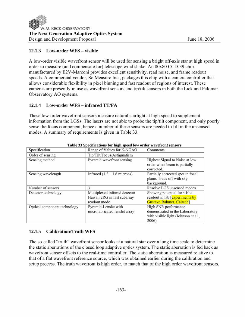
The Next Generation Adaptive Optics System Design and Development Proposal June 18, 2006
-163-
12.1.3 Low-order WFS – visible
A low-order visible wavefront sensor will be used for sensing a bright off-axis star at high speed in order to measure (and compensate for) telescope wind shake. An 80x80 CCD-39 chip manufactured by E2V-Marconi provides excellent sensitivity, read noise, and frame readout speeds. A commercial vendor, SciMeasure Inc., packages this chip with a camera controller that allows considerable flexibility in pixel binning and fast readout of regions of interest. These cameras are presently in use as wavefront sensors and tip/tilt sensors in both the Lick and Palomar Observatory AO systems. 12.1.4 Low-order WFS – infrared TT/FA
These low-order wavefront sensors measure natural starlight at high speed to supplement information from the LGSs. The lasers are not able to probe the tip/tilt component, and only poorly sense the focus component, hence a number of these sensors are needed to fill in the unsensed modes. A summary of requirements is given in Table 33.
Table 33 Specifications for high speed low order wavefront sensors Specification Range of Values for K-NGAO Comments Order of sensing Tip/Tilt/Focus/Astigmatism Sensing method Pyramid wavefront sensing Highest Signal to Noise at low
order when beam is partially corrected.
Sensing wavelength Infrared (1.2 – 1.6 microns) Partially corrected spot in focal plane. Trade off with sky background.
Number of sensors 3 Resolve LGS unsensed modes Detector technology Multiplexed infrared detector
Hawaii 2RG in fast subarray readout mode
Showing potential for <10 e- readout in lab [experiments by Gustavo Rahmer, Caltech]
Optical component technology Pyramid-Lenslet with microfabricated lenslet array
High SNR performance demonstrated in the Laboratory with visible light (Johnson et al., 2006)
12.1.5 Calibration/Truth WFS
The so-called “truth” wavefront sensor looks at a natural star over a long time scale to determine the static aberrations of the closed loop adaptive optics system. The static aberration is fed back as wavefront sensor offsets to the real-time controller. The static aberration is measured relative to that of a flat wavefront reference source, which was obtained earlier during the calibration and setup process. The truth wavefront is high order, to match that of the high order wavefront sensors.

The Next Generation Adaptive Optics System Design and Development Proposal June 18, 2006
-164-
Table 34 Truth wavefront sensor specifications Specification Range of Values for K-NGAO Comments Type Shack-Hartmann Order 44 across To match high order WFS
pointed at laser guidestars Integration time Seconds to minutes Average out atmospheric seeing Noise considerations Low dark current
Matched filter algorithm Reasonably periodic update at high SNR
12.2 Wavefront Correction
12.2.1 Deformable mirrors
12.2.1.1 Piezo-actuated
Piezo-electric actuated deformable mirrors have been the mainstay for astronomical adaptive optics systems, with a long history of development for aerospace application since the 1980s. They are still the only means of achieving high order actuation of large optics at the high speeds required for AO. The NGAO system will use one high order deformable mirror to address the entire AO field of regard. A summary of parameters is given in Table 35.
Table 35 Piezo deformable mirror for Keck NGAO Specification Range of Values for K-NGAO Comments Order of correction 44 – 64 across Impact on fitting error and static
telescope correction budget terms Interactuator spacing 5 mm Current technological minimum
with required stroke Overall size >~300 mm Minimize pupil magnification
distortion and Lagrange invariant angles
Stoke 3-5 microns surface Dynamic range of incoming wavefront aberrations
Speed of response >1.5 kHz Impact on control bandwidth error
The technology for piezo actuated mirrors, although mature, is challenged by the high actuator count and high stroke to interactuator spacing ratio demands of NGAO. A mirror that meets these requirements is currently under development for TMT by the CILAS Corporation. They have finished a feasibility design study for a 4200 actuator mirror for the TMT NFIRAOS instrument and have tested a 5x5 actuator prototype, designed specifically for sub-zero operating temperatures, in the laboratory. Xinetics Inc. also has significant expertise in electrostrictive actuator DM fabrication, and is currently under contract to develop a 662 actuator DM having 1.8mm actuator pitch and > 1.5 μm physical stroke for use in the Palomar Observatory Adaptive Optics System. Xinetics, Inc. has also been developing a novel DM technology using bimorph-like actuation of large SiC mirrors. This technology has been shown to provide large physical

The Next Generation Adaptive Optics System Design and Development Proposal June 18, 2006
-165-
stroke on coarse actuator spacing and is thought to be scalable to finer scales for potential application for correction of atmospheric turbulence. One interesting advantage of this technology is the straightforward process by which both spherical and aspheric deformable mirrors could be produced, potentially improving NGAO optical transmission. 12.2.1.2 MEMS based
MEMS actuators are a relatively new technology that promises high order correction in a small low cost package. Since MEMS deformable mirrors are based on electrostatic actuation, their response to applied voltage is precisely repeatable and predictable, as compared to the hysteretic behavior of piezo actuators. Current MEMS technology is limited in stroke and aperture size however, and can only be used in tandem with a large stroke deformable mirror functioning as the “woofer.” Hence the NGAO design has one woofer in the wide field relay optics upstream of the MEMS mirrors. MEMS will be used in NGAO as MOAO deformable mirrors operating in open-loop. They function to remove the large field-dependent anisoplanatic error that would result from using only one DM, enabling the multiple channel MOAO mode on a wide field. They also greatly improve AO sky coverage by making dimmer natural stars usable for tip/tilt determination.
Table 36 MEMS deformable mirror for K-NGAO Specification Range of Values for K-NGAO Comments Order of correction 4096 (64 across) Impact on fitting error and
anisoplanatic error budget terms Interactuator spacing 400 microns Current BMC mirror design Overall size 25 mm Stoke 3.5 - 4 microns surface Speed of response >2.7 kHz Go to accuracy < 30 nm rms Operated open loop
A summary of both piezo-actuated and MEMS deformable mirror technology development is given in Table 37.
Table 37 Deformable mirror technology status DM Technology Technology Status Piezo-actuated
Stroke 5 microns / 200V (CILAS TMT protype) Hysteresis 5% Hysteresis (CILAS TMT protype)
Development status
• CILAS 5 mm pitch device at feasibility design stage, with prototype actuators tested
• Xinetics 7 mm pitch mirror demonstrated on sky MEMS electrostatic actuated

The Next Generation Adaptive Optics System Design and Development Proposal June 18, 2006
-166-
Stroke • 4 microns (on 140 actuator device sold commercially by BMC) • 3.5 microns on 4096 actuator device for Gemini Planet Imager (now
under contract with BMC) Repeatability, Open Loop
• <1 nm (wavefront phase) repeatability for any voltage change, demonstrated in the lab with a 1024 actuator mirror
• <30 nm (wavefront phase) go-to proscribed surface shape in open-loop, demonstrated in lab with a 1024 actuator mirror
Development status
• Boston Micromachines Inc. produces the only high order MEMS shown capable of correcting atmospheric aberrations (tests at LLNL, 2003)
• Several other manufacturers working on higher stroke actuator designs
12.3 Tip/Tilt Control
12.4 Metrology
In the current Keck AO system a phase-shifting interferometer is used to set the DM to a desired shape as part of the process of image sharpening on the science instrument focal plane (required because of DM actuator hysteresis). It has also proved to be a useful qualitative tool for evaluating the seeing and diagnosing problems with the DM. A similar tool will need to be evaluated for the NGAO system. Other metrology may be required to monitor the relative position of the science instruments with respect to the AO system to compensate for any mechanical drift. 12.5 Real-time Controller
A key challenge of implementing a multi-guidestar AO system on a large astronomical telescope is the extraordinary amount of computation needed to perform tomography calculations hundreds of times per second in order to keep up with the changing atmosphere. Our investigation of the algorithms and data flow needed for AO real time processing and control has suggested that a massively parallel architecture using current state-of-the-art field-programmable gate arrays (FPGAs) can readily accomplish this task. 12.5.1 Real-time control requirements
Real-time control issues are summarized in Table 38.
Table 38 Real time control specifications for Keck NGAO Control bandwidth >100 Hz Wavefront sensor frame rate 1 kHz Number of wavefront sensors Up to 10
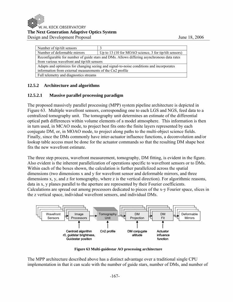
The Next Generation Adaptive Optics System Design and Development Proposal June 18, 2006
-167-
Number of tip/tilt sensors 3 Number of deformable mirrors Up to 13 (10 for MOAO science, 3 for tip/tilt sensors) Reconfigurable for number of guide stars and DMs. Allows differing asynchronous data rates from various wavefront and tip/tilt sensors Adapts and optimizes for changing seeing and signal-to-noise conditions and incorporates information from external measurements of the Cn2 profile Full telemetry and diagnostics streams
12.5.2 Architecture and algorithms
12.5.2.1 Massive parallel processing paradigm
The proposed massively parallel processing (MPP) system pipeline architecture is depicted in Figure 63. Multiple wavefront sensors, corresponding one to each LGS and NGS, feed data to a centralized tomography unit. The tomography unit determines an estimate of the differential optical path differences within volume elements of a model atmosphere. This information is then in turn used, in MCAO mode, to project best fits onto the finite layers represented by each conjugate DM, or, in MOAO mode, to project along paths to the multi-object science fields. Finally, since the DMs commonly have inter-actuator influence functions, a deconvolution and/or lookup table access must be done for the actuator commands so that the resulting DM shape best fits the new wavefront estimate. The three step process, wavefront measurement, tomography, DM fitting, is evident in the figure. Also evident is the inherent parallelization of operations specific to wavefront sensors or to DMs. Within each of the boxes shown, the calculation is further parallelized across the spatial dimensions (two dimensions x and y for wavefront sensor and deformable mirrors, and three dimensions x, y, and z for tomography, where z is the vertical direction). For algorithmic reasons, data in x, y planes parallel to the aperture are represented by their Fourier coefficients. Calculations are spread out among processors dedicated to pieces of the x-y Fourier space, slices in the z vertical space, individual wavefront sensors, and individual DMs.
ImageProcessorsImage
ProcessorsImageProcessorsImage
Processors
WavefrontSensorsWavefront
SensorsWavefrontSensorsWavefront
SensorsTomography
Unit
ImageProcessorsImage
ProcessorsImageProcessorsDM
Fit
WavefrontSensorsWavefront
SensorsWavefrontSensorsDMProjection
DM conjugatealtitude
Cn2 profile Actuatorinfluencefunction
Centroid algorithmr0, guidstar brightness,
Guidestar position
ImageProcessorsImage
ProcessorsImageProcessorsDeformable
Mirrors
ImageProcessorsImage
ProcessorsImageProcessorsImage
Processors
WavefrontSensorsWavefront
SensorsWavefrontSensorsWavefront
SensorsTomography
Unit
ImageProcessorsImage
ProcessorsImageProcessorsDM
Fit
WavefrontSensorsWavefront
SensorsWavefrontSensorsDMProjection
DM conjugatealtitude
Cn2 profile Actuatorinfluencefunction
Centroid algorithmr0, guidstar brightness,
Guidestar position
ImageProcessorsImage
ProcessorsImageProcessorsDeformable
Mirrors
Figure 63 Multi-guidestar AO processing architecture The MPP architecture described above has a distinct advantage over a traditional single CPU implementation in that it can scale with the number of guide stars, number of DMs, and number of

The Next Generation Adaptive Optics System Design and Development Proposal June 18, 2006
-168-
subapertures by simply adding processor cards without affecting the data throughput rate or the software program significantly. 12.5.2.2 Image processing and wavefront sensing
In the proposed MPP control architecture the processing tasks are divided up logically and associated as much as possible with the corresponding hardware. Each wavefront sensor has a wavefront reconstructor unit associated with it such that the data are preprocessed noise-optimally at the wavefront sensor level according to the signal to noise conditions for that sensor. Data are presented to the tomography unit in the form of wavefront phase, as if each sensor were a direct phase sensor. Sensors dedicated to measuring only low order modes, such as tip/tilt/focus/astigmatism, will also present their data to the tomography unit as wavefronts in order to facilitate tomographic processing. The wavefront phase estimates provide all the information that is inherent in the measurements for the tomography unit to optimally estimate the volumetric distribution of turbulence. Pre-processing pixel data from a Hartmann wavefront sensor is itself massively parallelizable. The steps include
• read data from the sensor array • background subtract • flat field • compute centroids using template-multiply (templates exist for quad-cell, center of mass,
and matched filter algorithms) Since multiple processors can be interfaced to the array along parallel interface lines, the array itself should be designed with many parallel readout amplifiers to minimize transfer time. The interface to the new CCID56 polar coordinate CCD will be designed with this in mind. Computing the wavefront phase given the slopes is a problem related to that of solving Poisson’s equation in two dimensions within the bounded region defined by the aperture. These calculations can be performed very rapidly in the Fourier domain since, once the Fourier coefficients of slope-x and slope-y are determined, one simply multiplies by a scalar coefficient at each spatial frequency to determine the Fourier coefficients of phase. These scalar coefficients are determined by the slope operator and the signal to noise ratio. They are computed by a separate processor and fed as low bandwidth updates to the real time processor. The processing of wavefront sensor camera data is summarized in Table 40
Table 39 Definition of symbols Symbol Meaning N Number of subapertures across one dimension of the aperture Ngs Number of guide stars = number of wavefront sensors Ndm Number of deformable mirrors

The Next Generation Adaptive Optics System Design and Development Proposal June 18, 2006
-169-
NL Number of layers in model atmosphere Npix Number of pixels on CCD chip (total) Nsub Number of pixels in a Hartmann subap (total) fs, T=1/fs Wavefront sensor sample rate, Hz; sample cycle time, seconds
Table 40 Processing steps from Hartmann slopes to wavefront phase. Processing step Algorithm Number of
Processors Number of Clock Cycles
1 Read data from camera Parallel readout from CCD
Npix/# of read amps
2 Background subtract and Flat field multiply
Multiply-add N×N×Ngs Nsub
3 Compute centroids Template multiply, sum, and scale result
N×N×Ngs 1+Nsub + 1 (assumes 3 adders in each processor)
4 Boundary slope conditioning Curl-free extension (Poyneer, 2002)
2πN×Ngs 2πN
5 Fourier transform FPGA/DFT N×N×Ngs 3N 6 Slope to phase Complex multiply-
add N×N×Ngs 3
7 Pupil distortion correction Cubic spline N×N×Ngs 16 8 Transfer data to tomography processor N
12.5.2.3 Tomography
Tomography is accomplished with an iterative back-propagation algorithm depicted in Figure 3 (Gavel, 2004).
Table 41 Tomography processing steps
Processing step Algorithm Number of Processors
Number of Clock Cycles
1 Subtract estimate from data Add N×N×Ngs 1 2 Precondition Complex Multiply N×N×Ngs Ngs
Figure 3. Block diagram of tomography calculation unit.
Back-propagate
Post-condition
Forward-propagateFT FT-1X
Aperture
WFSdata
VolumetricδOPDestimates-+
Pre-condition FT-1 FTX
Aperture
Back-propagate
Post-condition
Forward-propagateFT FT-1X
Aperture
WFSdata
VolumetricδOPDestimates-+
Pre-condition FT-1 FTX
Aperture

The Next Generation Adaptive Optics System Design and Development Proposal June 18, 2006
-170-
3 Inverse transform FPGA/DFT N×N×Ngs 3N 4 Aperture mask Multiply N×N×Ngs 1 5 Transform FPGA/DFT N×N×Ngs 3N 6 Back propagate, interpolating LGS
cone beams Multiply accumulate, cubic spline
N×N×NL NL+16
7 Post condition Multiply N×N×NL 1 8 Forward propagate, interpolating LGS
cone beams Sum, cubic spline N×N×NL NL+16
9 Inverse transform FPGA/DFT N×N×Ngs 3N 10 Aperture mask Multiply N×N×Ngs 1 11 Transform FPGA/DFT N×N×Ngs 3N Iterate steps 1-11 approximately 5
times per sample time step T to get a solution consistent with WFS measurements
12.5.2.4 Projection and fitting to DMs
Projection is the process of determining the desired phase correction at each DM given the tomographically determined estimate of differential phase aberrations over the atmospheric volume. For MOAO, this is simply the line integral of the turbulence estimate through the volume in the direction of interest. For MCAO, each conjugate mirror uses a weighted integral through the volume. From the prospective of the MPP architecture, this computation is identical in both configurations; it merely uses different weighting coefficients in the line integral. Fitting involves deconvolving the DM’s unit response function so that a voltage command can be determined given the desired surface shape. In the case of MEMS in open loop operation, it is necessary to use an additional cascade of two non-linear lookup tables. The computationally equivalent “deconvolution” step for MEMS determines the plate forces that need to be applied to the mirror to give the desired plate displacement. Then two lookup tables determine a) the actuator spring return force at the desired displacement and b) the actuator voltage necessary for the electrostatic force to equilibrate the resultant actuator forces. MPP processing steps are summarized in Table 42.
Table 42 Deformable mirror real time processing steps Processing step Algorithm Number of
Processors Number of Clock Cycles
1 Projection Multiply accumlate N×N×NL NL 2 Pupil distortion correction Cubic spline N×N×Ndm 16 3 Deconvolution Complex multiply N×N×Ndm 1 4 Inverse transform FPGA/DFT N×N×Ndm 3N
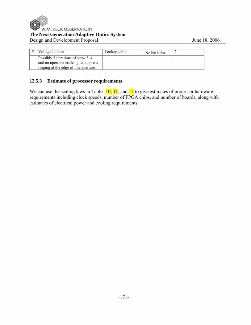
The Next Generation Adaptive Optics System Design and Development Proposal June 18, 2006
-171-
5 Voltage lookup Lookup table N×N×Ndm 2 Possibly 3 iterations of steps 3, 4,
and an aperture masking to suppress ringing at the edge of the aperture
12.5.3 Estimate of processor requirements
We can use the scaling laws in Tables 10, 11, and 12 to give estimates of processor hardware requirements including clock speeds, number of FPGA chips, and number of boards, along with estimates of electrical power and cooling requirements.
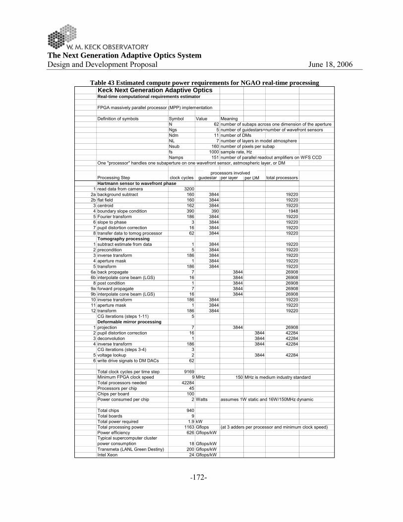
The Next Generation Adaptive Optics System Design and Development Proposal June 18, 2006
-172-
Table 43 Estimated compute power requirements for NGAO real-time processing Keck Next Generation Adaptive OpticsReal-time computational requirements estimator
FPGA massively parallel processor (MPP) implementation
Definition of symbols Symbol Value MeaningN 62 number of subaps across one dimension of the apertureNgs 5 number of guidestars=number of wavefront sensorsNdm 11 number of DMsNL 7 number of layers in model atmosphereNsub 160 number of pixels per subapfs 1000 sample rate, HzNamps 151 number of parallel readout amplifiers on WFS CCD
One "processor" handles one subaperture on one wavefront sensor, astmospheric layer, or DM
Processing Step clock cyclesper
guidestar per layer per DM total processorsHartmann sensor to wavefront phase
1 read data from camera 32002a background subtract 160 3844 192202b flat field 160 3844 192203 centroid 162 3844 192204 boundary slope condition 390 390 19485 Fourier transform 186 3844 192206 slope to phase 3 3844 192207 pupil distortion correction 16 3844 192208 transfer data to tomog processor 62 3844 19220
Tomography processing1 subtract estimate from data 1 3844 192202 precondition 5 3844 192203 inverse transform 186 3844 192204 aperture mask 1 3844 192205 transform 186 3844 19220
6a back propagate 7 3844 269086b interpolate cone beam (LGS) 16 3844 269088 post condition 1 3844 26908
9a forward propagate 7 3844 269089b interpolate cone beam (LGS) 16 3844 2690810 inverse transform 186 3844 1922011 aperture mask 1 3844 1922012 transform 186 3844 19220
CG iterations (steps 1-11) 5Deformable mirror processing
1 projection 7 3844 269082 pupil distortion correction 16 3844 422843 deconvolution 1 3844 422844 inverse transform 186 3844 42284
CG iterations (steps 3-4) 35 voltage lookup 2 3844 422846 write drive signals to DM DACs 62
Total clock cycles per time step 9169Minimum FPGA clock speed 9 MHz 150 MHz is medium industry standardTotal processors needed 42284Processors per chip 45Chips per board 100Power consumed per chip 2 Watts assumes 1W static and 16W/150MHz dynamic
Total chips 940Total boards 9Total power required 1.9 kWTotal processing power 1163 Gflops (at 3 adders per processor and minimum clock speed)Power efficiency 626 Gflops/kWTypical supercomputer cluster power consumption 18 Gflops/kWTransmeta (LANL Green Destiny) 200 Gflops/kWIntel Xeon 24 Gflops/kW
processors involved

The Next Generation Adaptive Optics System Design and Development Proposal June 18, 2006
-173-
12.5.4 Diagnostic and Telemetry Streams
The MPP architecture is amenable to real-time data-streaming to RAID disks for later post-processing and / or diagnosis at full frame rate. The data streaming I/O is established on a separate FPGA data bus so that its overhead almost transparent to the real-time control processing. 12.6 Laser Guide Star Facility
12.6.1 Requirements
Laser beacons for large telescopes should preferably be at high altitude in order to 1) probe the entire atmosphere and 2) minimize the cone beam effects, which otherwise would drive up the number of beacons required. For this reason, 10 meter class telescopes benefit most from lasers that stimulate fluorescent scattering in the mesosphere at 90 km altitude. The largest cross section atomic resonance is from Sodium on the D2 line at 588.9 nm wavelength. This line is Doppler broadened to about 1.5 GHz. Unfortunately, this is not a natural resonance line for typical laser materials and also this wavelength is not of much commercial interest, so only a few lasers are currently in existence that can put out the 10’s of Watts needed to provide a reasonably bright beacon for wavefront sensing. There are promising developments of solid state lasers for adaptive optics however, which we describe in the Laser Technology section below. For Keck NGAO, the nominal requirements on the laser are summarized in Table 44. Each of these requirements is described in subsequent sections.
Table 44 Laser Beacon Requirements Number and altitude of guidestars 5 at 90 km Brightness of guidestars Return > 100
photons/subaperture/beacon/sample time Pulse format Chosen to efficiently stimulate the
mesospheric Sodium. Preferably formatted to allow Rayleigh rejection and elongation compensation.
Launch telescope Behind the telescope secondary. Large enough projection aperture to minimize beacon spot size in normal seeing.
Transport from laser to launch telescope Low loss. Preferably by fiber for preservation of beam quality and ease of design

The Next Generation Adaptive Optics System Design and Development Proposal June 18, 2006
-174-
12.6.1.1 Number of guidestars
Multiple laser guidestar beacons are needed in order to provide enough data for tomographic reconstruction of the atmospheric volume above the telescope. Sufficient numbers and sample density of guidestars on the sky 1) assure that all the atmosphere in the science field is sampled by guide star rays and 2) resolve the atmosphere vertically so to determine field angle dependent wavefront corrections.
To properly sample the upper atmosphere it is necessary to keep the guidestar constellation tight enough that ray cones still overlap at the upper turbulent layers. Assuming the significant turbulence occurs below 15 km, the guidestars must be spaced no more than 10m/15km = 137 arcsec apart for cone beam overlap.
To resolve the vertical structure of the atmosphere, the guidestar sample density will scale as
00~ δrΘ
where r0 is Fried’s seeing parameter and �0 is a characteristic thickness of the atmosphere. The Cn2 model we are using for the point design has a �0 of about 1km and r0 of 15-20 cm, therefore a guidestar every 30-40 arcseconds on the sky is required. Sampling of the 1.5-2 arcminute field envisioned for Keck NGAO can be accomplished with a guidestar pattern consisting of 4 or 5 guidestars on the field radius and one guidestar in the middle of the field.
12.6.1.2 Brightness of guidestars
Guidestars must be bright enough to accurately sense the wavefront in the presence of photon and detector noise. The number of detected photons required to achieve a given wavefront measurement error is proportional to the apparent solid angle of the beacon on the sky. For example with a round 2 arcsecond spot and a 23 cm subaperture, 100 photons will give a centroiding error of 0.2 arcsecond, translating to about 20 nm wavefront error after reconstruction. Extensive error budget calculations and tradeoffs will adjust this number but generally, on the order of 100 photons/beacon/subaperture/integration time will be required.
Models of return counts vs laser power are complicated and have large factors of both modeling uncertainty and variability due to statistics of the mesospheric Sodium density. We discuss the options and technologies available in the Laser Technology section below. On-sky testing of the various lasers, continued development of physical phenomenological models, and measurements of the mesospheric Sodium layer properties are ongoing efforts aimed toward the goal of establishing reliable return prediction models.
12.6.1.3 Pulse format
The macro-pulse format of the laser (pulse widths or bursts greater than 1 microsecond long) can be set up for ideally addressing the Sodium in the mesosphere and rejecting noise from lower altitudes. The micro-pulse format (pulse widths on the order of a nanosecond) can determine the

The Next Generation Adaptive Optics System Design and Development Proposal June 18, 2006
-175-
linewidth and other Sodium cross-section properties that will effect the power efficiency or return photons per laser Watt.
12.6.1.4 Elongation
The beacon formed by a CW laser propagating through the Sodium layer will appear elongated when it is imaged into Hartmann subaperture, spreading out radially by an amount proportional to the Hartmann subaperture’s distance from the center of the aperture. For Keck, the elongation is as much as 1.3 arcseconds, assuming the laser is projected from behind the secondary mirror. The elongated spot will degrade the centroiding accuracy proportionally unless the laser return is increased equally in proportion to compensate. A pulsed laser with on the order of 3 microsecond pulse width could in principle be tracked as it traverses through the Sodium layer, eliminating the elongation smearing and reducing laser power requirements.
12.6.1.5 Rayleigh gating
An appropriately pulsed laser has an advantage of allowing the wavefront sensing system to gate in the mesosphere return while blocking the Rayleigh backscatter from lower altitudes, thus eliminating some of the background noise. The distance to the sodium layer is approximately 90 km at zenith while Rayleigh backscatter is significant for the first ~30 km or so. The round trip time to the sodium layer is 600 microseconds and round trip time from a 30 km altitude is 200 microseconds, thus up to 400 microsecond pulse width could be Rayleigh gated. Shorter pulses will allow more than one pulse to be in the air at one time but the “gate” must be open for at least 67 microseconds, the round trip time through the sodium layer, plus the pulse width.
12.6.1.6 Bandwidth
Since the Sodium D2 line in the mesosphere is Doppler broadened to about 1.5 GHz, the width of the laser line will matter for return efficiency. A narrow band CW laser can use the peak of the absorption profile for maximum return per what but is subject to saturation because of the limited number of atoms in that Doppler bin. There are a number of ways to broaden the laser line: electro-optic phase modulation, transform broadening with a narrow pulse, and modeless (broad spectrum) lasing. Surprisingly, both the highest return per Watt and the highest total return at high power have been demonstrated with a very narrow band (10 kHz) CW laser.
12.6.2 Laser technology
A summary of Sodium laser technology is given in Table 45. Table 45 Sodium laser technology in use in astronomical adaptive optics systems. The latter two in this list are
under development through the NSF/NOAO Adaptive Optics Development program. Laser Technology
Telescope Pulse Format Bandwidth Output Power Return Efficiency Photons/s/cm2/Watt
Dye Lick, Keck 100 ns, at 11-25 kHz
EO broadened to 2 GHz
12 W ~10
Sum Frequency CW
Starfire Optical Range
CW 10 kHz natural line width
50 W 75-150

The Next Generation Adaptive Optics System Design and Development Proposal June 18, 2006
-176-
Sum Frequency Micro-Macro pulse
Palomar Mode-locked 2 ns micro-pulse, in 300 μs 100 MHz bursts at 400? Hz
Transform broadened to1 GHz
4 W 40
Sum Frequency Micro
Gemini North 1 ns micro, continuous burst
Transform broadened to 1 GHz
10 W Not yet completely determined. Appears to be ~20
Frequency doubled Raman shifted
VLT CW EO broadened to 500 MHz
3.5 W? unknown
Sum Frequency Fiber
(under development at Lawrence Livermore National Lab)
CW bursts at 10-20% duty cycle
10-100 kHz? 3 W in the lab to date untested
Sum Frequency Waveguide
(under development at Lockheed Martin Coherent Technologies)
Adjustable both micro pulse and macro bursts, or pure CW
Transform broadened
3 W in the lab to date untested
Because of the cumbersome transport and maintenance of liquid dye, along with the low power conversion efficiency (wall plug power to output power), it is probably infeasible to consider using dye lasers for multiple laser beacons at high power. The remaining laser technologies use solid state IR lasers which are combined in nonlinear mixing crystals to form the 589 nm light. These are described below.
12.6.2.1 Sum-frequency Micro-macropulse
Solid-state sum-frequency lasers based on the 1.06 μm and 1.32 μm transitions of Ni:YAG can directly produce the 589 nm light required to excite the D2 transition of sodium residing in the mesosphere. Using quasi-CW pump excitation and mode-locking, a macropulse/micropulse laser pulse format can be generated having particularly favorable return cross-section. One example of this technology is the Chicago Sum Frequency Laser (CSFL), in active use at Palomar Observatory. To date, the CSFL has produced 8.5W of D2 line power at 500 Hz macropulse repetition rate in the field, with the CSFL team (led by Prof. Edward Kibblwhite of U Chicago) pursing a one-year upgrade path to approximately 12-15 W at 800 Hz pulse rate. 12.6.2.2 Sum-frequency CW
The Starfire Optical Range has developed a CW sum frequency laser that has been tested on the sky at their 3.5 meter telescope site in New Mexico. So far two versions of this laser have been built, with output powers of 11 W and 50 W, and have been tested on the sky for beam quality and return efficiency. The beam quality is struggling (3 arcsecond spot), but the return results, thoroughly documented for the 11 W in two PASP papers, and presented for the 50 W at the 2006 SPIE Telescopes meeting, are quite high, 3-5 times higher than any of the lasers previously used

The Next Generation Adaptive Optics System Design and Development Proposal June 18, 2006
-177-
by the astronomical community. The narrow (10 kHz) linewidth addresses the peak of the Sodium response curve which may be responsible for much of this improvement, however the exact Sodium physics response to CW versus the continuous micropulse format (Gemini laser) remains an open subject of investigation.
12.6.2.3 Continuous micropulse
The recently delivered 10 Watt laser for the Gemini Observatory North telescope is still undergoing integration and testing. Preliminary measurements show it to be performing on par with the Keck dye laser, possibly brighter due to the narrower line width. This laser is transform broadened by the micropulse duration. The laser was built by Lockheed Martin Coherent Technologies (formally Coherent Technologies Incorporated) under contract with the Gemini Observatory.
12.6.2.4 Sum-frequency CW fiber (LLNL)
The Lawrence Livermore National Laboratory is developing, under AODP and CfAO support, a sum-frequency fiber laser that mixes 1530 and 938 nm IR lasers with a PPSLT mixing crystal. The otherwise CW format is broken into macropulses as short as 60 microseconds at 10-20% duty cycle. Since it provides a CW signal for microseconds the Sodium layer should respond with the same return efficiency as the SOR laser, which has already proven on the sky to yield as much as 5 times higher return efficiency as any other laser. The LLNL fiber laser demonstrated 3.5 W of 589 nm light in the laboratory last year. It is expected to produce 10 W given extrapolated predictions of PPSLT performance but this is yet to be demonstrated and (presumably) LBO is a fall back option (LBO is producing 10 W in the Gemini laser). One shortcoming of this laser is that although its pulse format is suitable for rejecting Raleigh it may not be capable of producing 3 microsecond pulses needed for mitigating spot elongation.
12.6.2.5 Sum frequency waveguide
This laser, being developed by Lockheed Martin Coherent Technologies with an express interest of targeting the astronomical ELT market, is also still in the laboratory under development. The laser is of a master oscillator / power amplifier design with waveguide amplifiers operating in saturation, so that there is great flexibility in chopping the oscillator into pulses using electro-optic modulators. The result is a completely adjustable pulse format, from CW to macro pulse to micro pulse. Should pure CW prove the best format for return efficiency (as is strongly indicated by the SOR laser results) then an “ideal” format would be a Rayleigh blocking 60 microsecond CW pulse at 2-3 kHz (multiple pulses in the air at once) or a 3 microsecond CW pulse for pulse tracking. LMCT, like LLNL, is depending on PPSLT frequency mixing crystals at high power but could also presumably fall back to LBO.
12.6.3 Transport options
Most of the lasers described need a stable, gravity invariant platform to remain aligned and operating with maximum efficiency and at proper wavelength. Therefore some means of
The Next Generation Adaptive Optics System Design and Development Proposal June 18, 2006
-178-
transporting the output high power laser light to the beam projector mounted to the telescope must be provided.
12.6.3.1 Optical transport
“Traditional” beam transport is through a series of relay optics and mirrors that take the beam from a Nasmyth or Coude position to the top of the telescope. This requires a rather complicated active pointing and centering system to assure that the laser ends up at the launch telescope input pupil with good stability and beam quality.
12.6.3.2 Fiber transport
Fiber transport is a potentially elegant and straightforward solution to the beam transport problem. Single mode polarization maintaining fibers that work at 10’s of Watts and ~100 m transport links are only in their infancy stages of development and implementation however. Air core and photonics crystal type fibers offer enhanced power handling capability before unwanted nonlinear effects such as SBS and Raman shifting rob power from the main laser line. The VLT has employed a photonics crystal fiber to bring 8 Watts of CW light to its launch telescope behind the telescope secondary mirror. Such fibers still need to be shown to be feasible for pulsed format lasers and polarization maintaining versions need to be developed.
12.7 References
Adkins, S., et al., “The design and optimization of detectors for adaptive optics wavefront sensing,” SPIE Proc. 6272-60 (2006). Gavel, D., “Tomography for multiconjugate adaptive optics systems using laser guide stars,” SPIE Proc. 5490, 1356-1373 (2004). Hardy, J.W., Adaptive Optics for Astronomical Telescopes, Oxford University Press (1998). Johnson, J.A., et al., “Pyramid wavefront sensing: theory and component technology development at LAO,” SPIE Proc. 6272-165 (2006).

The Next Generation Adaptive Optics System Design and Development Proposal June 18, 2006
-179-
13 APPENDIX. AO SYSTEM KEY FEATURES
Subsystem Key Features Motion Control Discussion Risk Trade Study
Located on Keck II left Nasmyth platform
Replaces oldest AO system
Clean room Humidity control Background light suppression Optics area cooled to -15C
Based on emissivity budget.
Separate electronics enclosure wih glycol cooling Shutter to protect window 1 Ventilation for personnel
AO Enclosure
Mounting to Nasmyth platform Optics bench Cover
Support Structure
Mounting to Nasmyth platform 4 arcmin diameter unvignetted field Window to transmit 0.55-14 um
Required by cooled AO enclosure
Window availability
3 mirror (K-mirror) image rotator 1
Off-axis parabola (OAP1)
Collimates beam & reimages primary onto DM. Conjugate to altitude for MCAO upgrade.
Option to upgrade above mirror to SiC DM Conjugate to 9.0 km. DM location at telescope pupil
Optical Relay Off-axis parabola (OAP2)
Identical to OAP1. Reconverges beam at same focal ratio & with same pupil location as that of the telescope.

The Next Generation Adaptive Optics System Design and Development Proposal June 18, 2006
-180-
62 subapertures across 10.949 m telescope primary mirror (65 actuator DM) 3.5 mm actuator pitch (217 mm pupil at DM) Deformable
Mirror 3 um surface stroke DM mounted on tip/tilt stage 2
Impact on DM performance
Impact on DM performance
± 2" on sky at 50 Hz closed loop BW Tip/tilt correction ± 5" on sky at 5 Hz Chopping at pupil
Tip/Tilt Stage Option for DM to perform high BW
2-position dichroic changer with: 1) T=1-14 & R=0.5-1.0 um. 2) T=0.9-5 & R=0.5-0.9 um. 1
Transmits light to IR science instruments & wavefront sensors
Large & difficult dichroics. Changing will impact lenslet-DM registration.
Dichroic capabilities
5-position dichroic changer with: 1) T=0.9-1.7 & R = 1.9-5 um. 2) T=0.9-1.35 & R = 1.5-5 um. 3) T = 1.4-1.7 & R = 0.9-1.35 um. 4) Mirror. 5) Open 1
Reflects z & J or H or K-band or all light to IR science instrument. Transmits to low order WFS & possibly an IR WFS.
2x Rotation stages for dichroics 1
One to select IR science instrument & one to select visible science instrument
2-position dichroic changer with: 1) T = 0.4-0.6 & R = 0.6-1.0 um. 2) Open 1
Reflects light to science instrument & transmits to visible WFS
2x 2-position mirror: in & out 1
One each to reflect light to NGS acquisition camera & LGS acquisition camera
Optical Switchyard
Sodium transmissive dichroic (T=0.589 & R = 0.4-0.58 or 0.6 um) 1
Reflects light to either the NGS WFS or the slow NGS WFS.
Atmospheric Dispersion Correction
Pointing corrections between wavefront sensing & science wavelengths

The Next Generation Adaptive Optics System Design and Development Proposal June 18, 2006
-181-
Removable visible atmospheric dispersion corrector (ADC) for visible science instruments 3
Removable IR ADC for NIR science instruments & low order wavefront sensor 3
5 Shack-Hartmann WFSs (need space for 6 more in future)
Rayleigh light on WFS
How to remove or calibrate out Rayleigh background
48x48 subaperture baseline
Motion to register lenslets.
Lenslets not registered to actuators
62x62 & 31x31 subaperture option
62x62 offers a graceful fallback from 48x48. 31x31 for low sodium return case
4x4 pixels/subaperture
Relative performance of 2x2, 4x4 & 8x8
256x256 pixel CCD with 1e read-noise at 1 kHz readout rate
CCID-56 under development
CCD not demonstrated yet
Center WFS located on-axis Four WFS translate radially from 10-50". Also need z-adjustment for field curvature. 4 x,y control for 5 lenslets for DM registration & changing lenslets 10
x,y control for assembly 2 For dispersion correction
LGS Wavefront Sensors (WFS)
Tracking to stay conjugate to Na layer 1
3 pyramid WFSs
Tip, tilt, focus, astigmatism sensing from NGS
Not yet demonstrated to provide good sky correction
2x2 subapertures per WFS
Fast low order (LO) NGS WFS
2x2 pixels per subaperture

The Next Generation Adaptive Optics System Design and Development Proposal June 18, 2006
-182-
0.9-1.7 um SNAP detector thermoelectrically cooled to -40C
Based on SNAP tests at Caltech
Camera not yet demonstrated
Sodium rejection notch filter
MOAO-correction for each LOWFS with 32x32 actuator MEMs mirror
MOAO & MEMs being demonstrated in Lick AO laboratory
MOAO/MEMs not demonstrated on sky
Move over 4' field to acquire NGS 9
Tracking 6
To compensate for differential atmospheric refraction between science & NGS wavelengths, &/or differential tracking. Could use 1-stage?
Visible light Shack-Hartmann
To sense slowly varying sodium layer induced aberrations seen by LGS WFS
12x12 subapertures 8x8 pixels/subaperture 5-120 sec exposures Sodium rejection notch filter To reject Rayleigh
Slow NGS WFS
Move around 2' diameter field 3 To acquire NGS Same as LGS WFS but over visible NGS mode only 62x62 & 31x31 lenslet options Spatial filter
NGS WFS Move around 1' diameter field 3
NGS acquisition camera
4' diameter fixed field at NGS focus 4' diameter fixed field at LGS focus LGS
acquisition camera
Translate to stay conjugate to Na layer 3 Telescope simulator Rotating pupil 1
Calibration unit
3 NGS sources (1 movable) 2

The Next Generation Adaptive Optics System Design and Development Proposal June 18, 2006
-183-
5 (expandable to 11) LGS sources with variable focus 1 6 LGS sources with variable focus for WF 1 Turbulence generator 2 Translating fold mirror to insert beam 1 White light source with ND filter wheel 1 ~ sodium wavelength light source
Instrument calibration arc lamps
Alignment & Diagnostic Tools
Interferometer to look at DM?
Total = 72
The Next Generation Adaptive Optics System Design and Development Proposal June 18, 2006
-184-
14 APPENDIX. WAVEFRONT ERROR BUDGET
The flow down of residual wavefront error performance requirements to system and subsystem design parameters is facilitated through the use of residual wavefront error budgets. Increased understanding of current LGS AO systems, gained through extensive experimentation and analysis of on-sky performance, has refined the development of wavefront error budgets in practical applications. For NGAO planning purposes, we have developed a number of wavefront error budgets as guidelines for the design trade studies to be performed in the System Design phase.
We chose here to organize the discussion of wavefront error budgets into high spatial frequency (high-order) and low spatial frequency (low-order) error terms, because the impact of these terms on AO system performance differ. High-order terms typically scatter light away from the diffraction-limited core of the point spread function (PSF), whereas low-order aberrations blur the core, but retain useful science information within a narrow angular radius around the target. Tip/tilt aberrations are the lowest order aberrations and typically have the effect of blurring the diffraction limited core by 5-50 milliarcseconds (the natural diffraction limit at a wavelength of 1.65 microns is 31 mas for the Keck telescopes). Details regarding the calculation of each of the high- and low-order error budget terms are described in Appendix XXX. The applicability of NGAO over the viewable sky is determined by the availability of NGS capable of providing low-order wavefront information with sufficient fidelity to maintain overall performance. NGAO, like all LGS AO systems, will be usable over the entire viewable sky. However, it's delivered performance will vary as a function of the specific NGS constellations available in the direction of each science target. Thus, we will typically quote the percentage of sky correctable at a particular performance level, as the sky fraction.
In each of the specific error budget cases described below, we take the liberty, on a point by point basis, of independently optimizing the high-order and low-order wavefront sensor sample rates to find the optimal balance between quality of wavefront measurement and latency in the application of the AO system correction. While truly continuous optimization of detector sample times is usually not available, experience with existing systems has shown that a finite set of 5-10 sample rates is sufficient to run near peak performance levels.
14.1 Example: Narrow-field science with LGS and tip/tilt NGS stars (KBO science
program)
NGAO will support multiple sources of low-order wavefront information, augmenting the higher-order wavefront aberration estimate provided by the LGS beacon asterism. In the simplest observing mode, the science target itself is used to determine the missing tip/tilt and focus information. In this case, there is no anisokineticism to degrade the value of the tip/tilt measurement and no angular anisoplanatism to compromise the sharpening of the low-order aberration source. A typical error budget for this case, assuming a target having mH = 15.75 and

The Next Generation Adaptive Optics System Design and Development Proposal June 18, 2006
-185-
science field of view of only 2 arcsec (e.g. OSIRIS observations), is shown in an error budget tree view in Figure 64.
Figure 64 Example error budget tree for KBO science case.
The actual development of this error budget has been undertaken using an adaptive optics performance planning and analysis tool developed by Dekany and Troy for the Palomar Adaptive Optics System and updated by Dekany and Neyman for the NGAO point design development. An example output for the tool is shown in Figure 65.
The detailed description of the key error budget terms are presented in a Appendix. Wavefront Error Budget Terms, but here we would like to point out some of the system-level issues for NGAO that are indicated in this KBO example. First, we see that the atmospheric error terms have been balanced against calibration terms, with each representing a significant improvement over the current AO system performance. Thus, NGAO development requires both advanced hardware components and better systems engineering and quality engineering, but also the development of improved calibration techniques. Second, this budget included 50 nm rms of telescope error that is uncorrectable by the NGAO system. The

The Next Generation Adaptive Optics System Design and Development Proposal June 18, 2006
-186-
exact limitations imposed by the telescope optics and dynamics are not well known, so meeting this level of allocation may well require engineering investigation of the telescope (particularly the primary mirror) and may require elements of performance improvement if these are shown to be required and cost-effective for NGAO. This is particularly true if we are to take advantage of superior seeing conditions, under which calibration and systematics errors can dominate the error budget.

The Next Generation Adaptive Optics System Design and Development Proposal June 18, 2006
-187-
Figure 65 Error budget summary for LGS mode having an on-axis tip/tilt reference source. This summary corresponds to an observation of a KBO having mH = 15.75, in median seeing conditions. Error terms
highlighted in light green are allocations; other terms are based on point design parameter choices. The most relevant choices are shown in this summary, with supporting assumptions described on detailed worksheets for each
error term.

The Next Generation Adaptive Optics System Design and Development Proposal June 18, 2006
-188-
14.2 Wavefront Error Budget Summaries
Figure 66 "Best conditions" narrow field case.

The Next Generation Adaptive Optics System Design and Development Proposal June 18, 2006
-189-
Figure 67 Io case.

The Next Generation Adaptive Optics System Design and Development Proposal June 18, 2006
-190-
Figure 68 Galactic Center case.

The Next Generation Adaptive Optics System Design and Development Proposal June 18, 2006
-191-
Figure 69 Field Galaxies case.
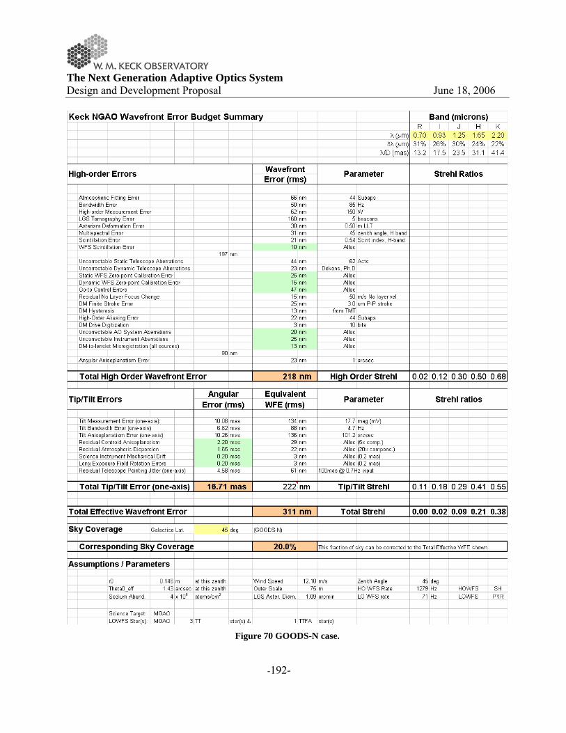
The Next Generation Adaptive Optics System Design and Development Proposal June 18, 2006
-192-
Figure 70 GOODS-N case.

The Next Generation Adaptive Optics System Design and Development Proposal June 18, 2006
-193-
15 APPENDIX. WAVEFRONT ERROR BUDGET TERMS
The wavefront error budgets developed for the NGAO point design incorporate the following physical sources of residual high-order (non-tip/tilt) wavefront error:
Atmospheric Fitting Error Bandwidth Error
High-order Measurement Error* LGS Tomography Error*
Asterism Deformation Error* Multispectral Error Scintillation Error*
WFS Scintillation Error* Uncorrectable Static Telescope Aberrations
Uncorrectable Dynamic Telescope Aberrations Static WFS Zero-point Calibration Error*
Dynamic WFS Zero-point Calibration Error* Go-to Control Errors*
Residual Na Layer Focus Change* DM Finite Stroke Error
DM Hysteresis High-Order Aliasing Error
DM Drive Digitization Uncorrectable AO System Aberrations Uncorrectable Instrument Aberrations
DM-to-lenslet Misregistration (all sources) Angular Anisoplanatism Error
and the following terms pertaining to tip/tilt errors:
Tilt Measurement Error
Tilt Bandwidth Error Tilt Anisoplanatism Error
Residual Centroid Anisoplanatism* Residual Atmospheric Dispersion*
Science Instrument Mechanical Drift* Long Exposure Field Rotation Errors* Residual Telescope Pointing Jitter*.
Most of these error terms are described in detail in the excellent text by J. W. Hardy, Adaptive Optics for Astronomy. Where no particular explanation of assumptions is required, we refer the reader to this useful reference. Some terms, however, require special description in this Appendix because they are either non-standard, or because critical assumptions have been made in their estimation. These terms are indicated with asterisks above and described in detail in the following sections.
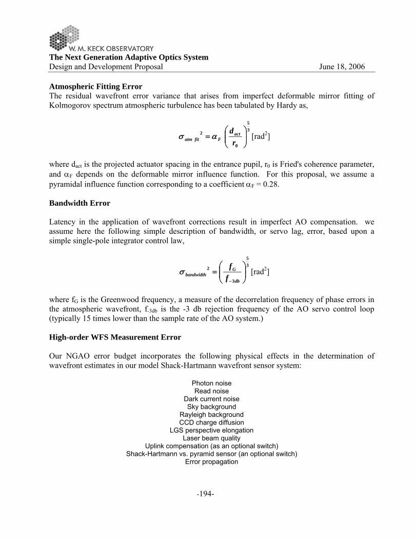
The Next Generation Adaptive Optics System Design and Development Proposal June 18, 2006
-194-
Atmospheric Fitting Error The residual wavefront error variance that arises from imperfect deformable mirror fitting of Kolmogorov spectrum atmospheric turbulence has been tabulated by Hardy as,
35
0
2⎟⎟⎠
⎞⎜⎜⎝
⎛=
rdact
Ffitatm ασ [rad2]
where dact is the projected actuator spacing in the entrance pupil, r0 is Fried's coherence parameter, and αF depends on the deformable mirror influence function. For this proposal, we assume a pyramidal influence function corresponding to a coefficient αF = 0.28. Bandwidth Error Latency in the application of wavefront corrections result in imperfect AO compensation. we assume here the following simple description of bandwidth, or servo lag, error, based upon a simple single-pole integrator control law,
35
3
2⎟⎟⎠
⎞⎜⎜⎝
⎛=
− db
Gbandwidth f
fσ [rad2]
where fG is the Greenwood frequency, a measure of the decorrelation frequency of phase errors in the atmospheric wavefront, f-3db is the -3 db rejection frequency of the AO servo control loop (typically 15 times lower than the sample rate of the AO system.)
High-order WFS Measurement Error Our NGAO error budget incorporates the following physical effects in the determination of wavefront estimates in our model Shack-Hartmann wavefront sensor system:
Photon noise Read noise
Dark current noise Sky background
Rayleigh background CCD charge diffusion
LGS perspective elongation Laser beam quality
Uplink compensation (as an optional switch) Shack-Hartmann vs. pyramid sensor (an optional switch)
Error propagation

The Next Generation Adaptive Optics System Design and Development Proposal June 18, 2006
-195-
We have, where appropriate, incorporated real-world values for these parameters, as measured in existing LGS AO systems, and/or noted 'next generation technology' in our discussion of risk areas central to System Design phase consideration.
Rayleigh scatter subtraction is particularly thorny should we adopt CW laser format for NGAO. The presence of high cirrus clouds has the potential to dramatically increase the sky background as to compromise LGS operations. We have assumed for the point design that CW Rayleigh scatter can be subtracted from the high-order wavefront sensor signal to the 10% level. Should this be shown to be insufficient or impractical, we could eliminate Rayleigh scatter altogether via use of a pulsed format sodium D2 line laser.
LGS Tomography Error Estimation of the residual wavefront error arising from incomplete or incorrect tomographic wavefront sensing has been explored in detailed covariance code models (D. Gavel, SPIE 2002 and private communication) and through Monte Carlo simulations (C. Neyman, private communications). The input parameters are the atmospheric turbulence profile, the laser guide star asterism beacon count and geometry, the field of view over which wavefront estimation is to be made, and certain assumptions regarding the mode of AO operation (e.g. single- vs. double-conjugate correction) and auxiliary sources of sensing information (e.g. concurrent measurement of certain wavefront spatial modes (such as focus and astigmatism) using natural guide stars). Tomography error is approximated by
35
0
2⎟⎟⎠
⎞⎜⎜⎝
⎛ Θ=
rtomogδσ
[rad2]
where Θ is the angular separation of multiple guidestars, r0 is Fried’s seeing parameter, and δ is the characteristic turbulent layer thickness as determined by the Cn
2 profile vertical distribution of turbulence. For the model atmosphere we are assuming, d is approximately 1 km. For the purpose of the point design, we have selected a specific asterism for narrow-field science applications and conducted a small trade study for wider-field science applications to identify the key areas for further investigation. For the corresponding error budgets, we have entered the estimated wavefront error determined from these detailed codes.
Asterism Deformation Error Tomographic reconstruction of multiple LGS wavefront measurements typically requirements an assumption on the actual geometry of the laser asterism on the sodium layer. However, due to tilt

The Next Generation Adaptive Optics System Design and Development Proposal June 18, 2006
-196-
indeterminacy of the individual beacons, the true sampling of the volume of atmosphere above the telescope is instantaneously variable. For example, the nominal square geometry of an asterism is at any given time in reality a general quadrilateral. Independent of blind modes in the reconstruction process, this unknown asterism deformation will lead to additional residual wavefront errors. We estimate the magnitude of this error by supposing that the wavefront reconstruction is diabolically bad, representing a volume of atmosphere in which the entire asterism has (unknowingly) conspired to shift in the same direction. In this case, the upper limit to the error is equivalent to an angular anisoplanatism error corresponding to the angular variance of the uplink laser tip/tilt, typically 0.2 to 0.3 arcsec, depending on zenith angle. The equivalent wavefront error in this case, for the CN-M2 atmospheric model, is typically 15 to 30 nm rms. Scintillation Error Via propagation, phase errors imparted on the wavefront at high altitudes in the Earth's atmosphere couple into amplitude errors generating the phenomenon of scintillation. We assume only phase compensation for the NGAO point design, resulting in a residual Strehl ratio degradation even for a system performing perfect phase conjugation. Standard formulae are therefore used to estimate the impact to Strehl in H-band and from this (via the Marechal approximation), an equivalent rms wavefront error in nanometers is determined. Note, this error budget term is chromatic and is most accurately presented in our point design budgets for wavelengths around H-band. More detailed analysis of this effect will be undertaken in the System Design phase. WFS Scintillation Error Just as scintillation directly degrades the delivered science image quality of NGAO, it also indirectly introduces wavefront compensation errors via coupling of phase and amplitude terms in our high-order wavefront sensors. Across the dimension of one WFS subaperture, scintillation of the wavefront would have no impact on a pure local tilt error alone. However, in the presence of local focus and other aberrations within a subaperture, amplitude fluctuations can be misinterpreted by the sensor as false tip/tilt signal, resulting in reconstruction errors. The magnitude of this error is typically small, but grows as subaperture dimension is reduced. We use estimates generated from diffractive wave-propagation Monte Carlo simulations of Shack-Hartmann wavefront sensor AO systems (Matt Britton, private communication) as the basis for a wavefront error estimate for the NGAO point design. Static WFS Zero-point Calibration Error

The Next Generation Adaptive Optics System Design and Development Proposal June 18, 2006
-197-
Static WFS zero-point calibration errors represent the difference between the physically obtainable internal wavefront calibration errors (e.g. those not outside the spatial bandwidth of deformable mirror actuator correction) and the actual internal calibration error. Dynamic WFS Zero-point Calibration Error Static zero-point calibration errors can be accentuated in the presence of changing atmospheric and other conditions. The centroid offset values, for example, representing the closed-loop desired target point for the AO system depend on the subaperture centroid gain function mapping true wavefront tilt to measured centroid tilt (all slope sensors are to some degree non-linear meters of the instantaneous wavefront state). Shack-Hartmann sensor systems design to operate away from strict 'quad-cell' centers are particularly susceptible to this error. For the NGAO point design, we estimate this error based on our experience with existing LGS AO systems that use Shack-Hartmann sensing in the presence of changing seeing and potentially changing laser beam quality. Interpreted as an allocation to the error budget, this would set an acceptable level of static wavefront errors and/or reference centroid positions.
Go-To Control Errors Multi-Object AO (MOAO) implementations considered in the NGAO point design require operation of individual high-order deformable mirrors in a go-to control mode. By this, we mean that no wavefront sensor witnesses the effects of the correction, rather it is imprinted upon the astronomical science light alone.
Experiments are underway at UCSC's LAO (D. Gavel, private communication) to establish the practical residual errors imparted by go-to AO systems. For the NGAO point design error budgets, we have assumed that the root-sum-squared total of each of:
Incorrect measurement of woofer DM - 30nm rms
Incorrect calibration of WFS - 20 nm rms Incorrect actuation of MEMS DMs - 2 nm rms
or equivalently 36 nm rms in all. Note, this applies only to the wide-field science modes of NGAO, as the narrow-field laser beacons do, in fact, witness compensation (if only partially). The detailed performance of go-to control systems will be further investigated in the System Design phase, including feedback from concurrently planned experimental verification. Residual Na Layer Focus Change The altitude of the Earth's sodium (Na) layer is ever-changing, resulting in the impression of an unpredictable focus error into the high-speed LGS wavefront sensor signal. The effect of these

The Next Generation Adaptive Optics System Design and Development Proposal June 18, 2006
-198-
focus changes can be measured in the low-order WFS system, where focus is continually and concurrently being measured using natural guide stars. The focus information necessary to compensate for Na layer altitude changes, however, can only be provided at the closed-loop correction bandwidth of the LOWFS, resulting in a residual Na layer focus error. Experimentally, we have data tracking the Na layer fluctuations over Mauna Kea (Antonin Bouchez, private communication). For the NGAO point design error budget, we assume conservatively an unpredictable sinusoidal altitude variation of 50 meters/sec vertical. This results in an input error of 37 nm rms per second, which is then reduced by the compensation provided by the LOWFS bandwidth (e.g. 5x reduction for 5 Hz -3db bandwidth). Residual Centroid Anisoplanatism Ideally, tip/tilt sensors would measure wavefront tilt but in practice they usually measure centroid motion as a surrogate to true tilt in the Zernike sense. Because other wavefront aberrations (notably coma) can also move the wavefront centroid, a centroid anisoplanatism error is introduced. A number of techniques have been proposed to mitigate this potentially significant effect (Dekens, F., Ph. D. thesis, University of Irvine). Current LGS systems typically rely on averaging of effects that arise because of the high characteristic frequency of coma and higher-order aberrations, relative to wavefront tilt.
For the NGAO point design error budget, we make an allocation corresponding to a 5x reduction in the intrinsic centroid anisoplanatism error, as measured by Dekens using ultra-fine-screen data from the Keck Phasing Camera System (PCS). This allocation can be realized via a number of techniques, but will require further analysis in the System Design phase before a particular strategy can be recommended. Residual Atmospheric Dispersion Atmospheric dispersion becomes an increasingly difficult problem as NGAO moves Keck science both to shorter wavelength and higher Strehl ratio. Atmospheric dispersion is a chromatic effect, wherein one cannot easily represent the error via the Marechal approximation. Still, we do just this in our error budgets, adopting the residual atmospheric dispersion that would be present across the J-band. (The import of this effect grows with shorter science wavelength.)
For the NGAO point design, we have assumed that the natural atmospheric dispersion can be reduced by a factor of 10x, setting an infrared design target for the System Design phase. Visible light science will need detailed analysis to determine the practical limits of compensator design, in the context of more highly developed visible-light science cases.
The Next Generation Adaptive Optics System Design and Development Proposal June 18, 2006
-199-
Science Instrument Mechanical Drift Due to typical non-common optical paths between the science focal plane and the NGAO tip/tilt sensor, slow thermal or gravitational drifts can cause blurring on the long-exposure science image.
For the NGAO point design, we assume 0.2 milliarcseconds as an allocation for the allowable non-common-path mechanical drift for short exposures (e.g. 10 seconds) and 2 milliarcseconds for the long exposures (e.g. 4 hours). Meeting these allocations may or may not require active metering of the non-common path.
Long Exposure Field Rotation Errors Imperfect field derotation of the alt-az provided science field relative to the science focal plane will result in a blurring. We allocate 0.2 milliarcsec for short exposure and 2 milliarcsec for long-exposures, as above, to these effects. Note, long-exposure in this case can represent any exposure that undergoes significant field derotation, including relatively short duration exposures need the keyhole. Residual Telescope Pointing Jitter Telescope windshake and other disturbance sources result in an equivalent solid-body pointing jitter. Work conducted on Keck Interferometer in recent years has significantly reduced the global vibration environment for the telescopes, but some pointing jitter remains.
For NGAO, we assume a sinusoidal model of jitter in which an initial disturbance having 0.1 arcsecond peak-to-peak amplitude and 0.7 Hz frequency is rejected at the NGAO tip/tilt -3db closed-loop bandwidth. Other Terms Not Considered Here For completeness, we note that our error budget development currently does not include the following error terms, almost always because we believe the impact to the system performance can be made negligible through appropriate design choice:
Non-linear DM Actuator Superposition Error (can addressed via proper reconstructor)
Tilt Sensor Scintillation Error (effect is small in IR w/ large subaps) Blind (e.g. Waffle) Modes (can be controlled via servo law)
Non-Common-Path Air Turbulence Non-Common-Path Mechanical Vibrations
Temperature Dependent DM Gain Changes (realized as a servo gain change) LGS Finite Altitude Error (negligible for Na beacons)
Errors due to incorrect control of 'guard ring' DM actuators Reconstructor Round-off Error

The Next Generation Adaptive Optics System Design and Development Proposal June 18, 2006
-200-
Some of these terms may be added to the design error budgets during system development, though none is currently envisioned to contribute a term larger than 10nm rms to be added in quadrature to the overall wavefront error budget.
The Next Generation Adaptive Optics System Design and Development Proposal June 18, 2006
-201-
16 APPENDIX: POINT SPREAD FUNCTION SIMULATIONS
16.1 Introduction
Several sets of point spread functions (PSF) for the NGAO system were generated using computer simulations. The simulations were intended to represent the image morphology of various high Strehl AO systems for determining the feasibility of example science cases. The simulations were not intended to be high fidelity representations of any “point” or system design. Many effects that must be evaluated in the final system error budget are not currently included in the computer models and were left out of the PSF simulations. However it is hoped that, the simulations are still useful for determining the level of correction that is needed for a particular science case to be feasible 16.2 Linear Adaptive Optics Simulator Code
The PSF were generated using a computer simulation developed at the Thirty Meter Telescope project office by Brent Ellerbroek and Luc Gilles. The computer code: Linear Adaptive Optics Simulator (LAOS) is a Monte Carlo simulation of a basic multiple laser guide adaptive optics system. Like all Monte Carlo simulations LAOS determines the performance of an AO system by using random number generators to simulate random processes in the physical system then averaging over these random events to determine the likely behavior of the system. LAOS uses random number generators to simulate atmospheric turbulence and noise in the photo detection process. Each randomly generated wavefront is measured and corrected using the computer in a way that is analogous to how it is corrected by the actual AO system. The LAOS simulation is coded in the MATLAB computer language, a high level language optimized for numerical computation. The LAOS simulation’s distinguishing feature from other AO Monte Carlo simulations is its minimum variance wavefront estimators using sparse matrix techniques (Ellerbroek, 2002). The user can select between two sparse matrix solvers, a computationally efficient multigrid preconditioned conjugate gradient (MG-PCG) algorithm (Ellerbroek, Gilles, and Vogel, 2003) or (ii) a sparse Cholesky solver (Ellerbroek, 2002). Further details of the LAOS code are discussed in its user manual published by TMT3. The LAOS code has been checked by Ellerbroek and Gilles, against analytical models of AO performance on 8-m telescopes. 16.2.1 Tomography:
The correction of the atmospheric turbulence is performed in two steps, the first is an estimation of the three dimensional turbulence above the telescope (tomography), followed by a fitting of the 3 LAOS: Linear Adaptive Optics Simulator, Luc Gilles and Brent Ellerbroek, TMT publication: TMT.AOS.TEC.05.084.DRF01
The Next Generation Adaptive Optics System Design and Development Proposal June 18, 2006
-202-
estimate to user selectable number of tip/tilt and deformable mirrors. In the tomography step the volume turbulence is estimated from a set of NGS and LGS measured with Shack-Hartmann sensors. This measurement is then used to generate the commands to a set of tip/tilt and deformable mirrors so that the residual wavefront error is minimized over a set of user selectable scientific observation points in the field of regard of the telescope. LAOS fitting step can be performed for both multiconjugate scenarios (MCAO) using a set of mirrors effectively located at different attitudes above the telescope pupil or multi object scenarios (MOAO) where independent deformable mirrors are used to correct each science direction. 16.2.2 Atmospheric model and propagation:
The atmospheric turbulence is modeled as a series, typically 7, of the infinitely thin phase perturbations or phase screens located at altitudes above the telescope pupil corresponding to strong layers of atmospheric turbulence. Each screen is statically independent random realization of the turbulence. The statistics of each screen are matched to Kolmogorov turbulence with or without a finite outerscale. The time evolution of the atmosphere is simulated by shifting the screen between updates of the AO control loop that are consistent with the wind velocity measured at altitude. The wavefronts for both NGS and LGS are calculated by summing the phase perturbations along ray paths from the source through the phase screens to the entrance aperture of the telescope. The LGS wavefronts are rescaled to simulate the conical ray paths that finite range LGS take through the atmosphere. This ray optics model of the atmospheric is generally considered appropriate when observing at astronomical sites where the wavefront amplitude variations (scintillation) are small. 16.2.3 DM and WFS models
Any simulation on an AO system must simulate the performance by a series of approximations. The LAOS code simulates the actuators on DMs by linear spline between actuator locations. This results in some increase in the AO system actuator fitting error over actuator models that use Gaussian functions or higher order polynomials. The wavefront sensor is simulated by the calculation of the average gradient4 of the wavefront phase over the subaperture area (technically it is the line integral of the phase around the boundary, but these are equivalent by Green’s theorem). This gradient is used as the noise free measurement. Other AO simulations actually calculate the image from each lenslet subaperture by a series of parallel diffraction calculations, one for each lenslet. In LAOS using the wavefront gradient directly results in a sensor model that is perfectly linear for all wavefront slopes. Further the response is not a function of the seeing or the size of the LGS spot and as such is immune to calibration errors that occur when the spot size is different than the spot size used to calibrate the system. Noise in the measurement process is simulated by a Gaussian noise added to the gradient 4 The latest release of LAOS in spring 2006 includes a both a gradient model and physical optics model of the wavefront sensor; we will be using these new features in future trades studies for the NGAO system design.

The Next Generation Adaptive Optics System Design and Development Proposal June 18, 2006
-203-
measurement. The user can set this value to simulate the magnitude of the guide star. For laser guide stars the effects of spot elongation are modeled by a directionally dependent noise for the gradient measurements. The AO control loop delay can be set to zero in LAOS to simulate perfect temporal correction (infinite bandwidth control system). Delays can also be added to the control loop to simulate the delay between sensing and correction that occur in any realistic control system. LAOS is unique in that it uses wavefront estimators (reconstructors) that require knowledge of the open loop wavefront error. LAOS simulation estimates the open loop wavefront error from the closed loop measurements and the shape of the deformable mirrors. It has been shown that this type of control results in closed loop stability and robustness against system errors, see Gilles 2005 for more detail on pseudo open-loop control. 16.2.4 Segmented telescope primary (M1)
The LAOS simulation has the ability to simulate the effects of static aberrations located at the telescope primary mirror (M1). The aberrations are defined on segments that tile the entrance pupil of the telescope. The aberrations can be the result of positioning the segments relative to one another and higher order aberrations of the individual segment shapes or “optical figures” up to fifth order Zernike polynomials. The rms values of these segment errors are used to generate a random set of errors for the segments on the telescope. The same error set was used for all simulations. The rms values used were taken from typical values from measurements from the PCS system on the two Keck telescopes. Its is important to note that these errors don’t correspond to the exact values on either Keck I or Keck II but should give a reasonable estimate to the performance expected from using AO systems behind one of these telescopes. 16.3 Simulations for NGAO science case
All simulations for the NGAO science case were done using the November 2005 release of the LAOS code. It was modified to accommodate a Keck pupil in the PSF computations but the AO simulation was conducted on a round 11 m pupil. The resulting AO corrected wavefront was masked to a Keck segmented pupil and Fourier transformed to produce the final PSF. The segment gaps were accounted for using the gray pixel approximation of Troy and Chanan. A circular secondary obscuration was added to the final pupil mask; secondary supports (spiders) were not modeled. 16.3.1 Simulation of narrow field of view AO, on axis PSF
The original baseline for NGAO (then KPAO) performance was 120 nm rms wavefront error delivered to the user as detailed in KAON 237. This level of performance is a significant enhancement over both the current Keck NGS performance, 250 nm, and the LGS performance, 350 nm. As mentioned in the introduction these simulations were undertaken to simulate the

The Next Generation Adaptive Optics System Design and Development Proposal June 18, 2006
-204-
performance gains when observing with an AO system with sub 200 nm rms wavefront error. Some terms (see Table 46) were not included in the modeling of the PSF but they are included in error budgets for the current proposed point design. The terms left out of the PSF modeling account for about ~80 nm in the higher order error budget of the point design. The terms included in the point design error budget and in the simulations total for the same seeing conditions would total about ~70 nm in the point design. In order to achieve the mandated 120 nm for the simulations of the PSF, the AO systems that were simulated have fewer actuators, more noise, lower bandwidth and fewer lasers than in the point design. The resulting higher order error was 90 nm rms; when this is combined with an 8 mas tracking blur the resulting total wavefront error is 120 nm.
Error Term Point Design PSF simulation Comments Atmospheric Fitting Error Yes Yes Bandwidth Error Yes Yes High-order Measurement Error Yes Yes LGS Tomography Error Yes Yes Multispectral Error Yes No Scintillation Error Yes No WFS Scintillation Error Yes No Uncorrectable Telescope Aberrations
Yes Partial Only lower order Zernikes
Static WFS Zero-point Calibration Error
Yes No
Dynamic WFS Zero-point Calibration Error
Yes No
Residual Na Layer Focus Change Yes No DM Finite Stroke Error Yes No DM Hysteresis Yes No High-Order Aliasing Error Yes Yes Uncorrectable AO System Aberrations
Yes No
Uncorrectable Instrument Aberrations
Yes No
DM-to-Lenslet misregistration Yes No Table 46 The various terms used in the current point design error budget for NGAO.
In addition to the KAON 237 wavefront error of 120 nm, similar simulations were run with 140 nm rms wavefront error and 170 nm wavefront error (these are sums of higher order wavefront error and tracking errors of 5 mas). A single LGS simulation was also run that produced 250 nm wavefront error as a simulation of the “best possible” performance with the upgraded Keck I LGS AO system. The sets of simulations all represented one second of integration. A set of 10 second

The Next Generation Adaptive Optics System Design and Development Proposal June 18, 2006
-205-
integrations were produced for the 120 nm wavefront case. These PSF were similar so that it was felt that the one second integration time was an adequate representation. A grid of simulation PSF is for the 120 nm case is shown in Figure 71.
Figure 71 Grid of 120 nm PSF from LAOS simulations. Each column represents a different wavelength band columns starting from the left are wavelengths of 0.55 μm, 0.65 μm, 0.85 μm, 1.2 μm, 1.65 μm, 2.2 μm, corresponding to the centers of the V, Rc, Ic, J, H, and K photometric
bands. Each row corresponds to different tip/tilt errors starting at the top single axis tip tilt errors are: 0 mas, 8 mas, 15 mas, and 25 mas. Each individual PSF is approximately 0.8 arcseconds on a side. The total rms wavefront error
for the second row down from the top is 120 nm. 16.3.2 High contrast simulations
At the request of the science teams some additional simulations were produced to access the contrast obtainable when observing dim targets. A typical science observation of this type would be the detection of dimmer companion in a binary brown dwarf. The simulations included running the narrow field case for a five second integration. The effects of an idealized coronagraph were simulated by applying a Blackman window to the pupil of the telescope. This apodization effectively suppresses diffraction at angular scales greater than ~5 times the diffractions limit (λ/D) at the expense of degrading angular resolution. While such an apodization is not easy constructed it is similar in performance to a Lyot coronagraph and is easier to simulate. In addition the apodization still allows the central star to be visible in the simulation PSF, but with

The Next Generation Adaptive Optics System Design and Development Proposal June 18, 2006
-206-
suppressed wings of the diffraction pattern, this should make is possible to combine the PSF with a model of the science object. 16.3.3 Seeing variability simulations
In addition to the KAON 237 based simulations for 120nm wavefront error with good seeing, a set of ten one second simulations with different values of r0 were produced to estimate the effects of observations made in changing atmospheric conditions. The values of r0 range from 9 cm to 24 cm at 0.5 μm wavelength. 16.4 Future simulations
The current set of PSFs are only in approximate agreement with the point design error budget. This is not surprising since the PSFs were simulations to match the wavefront error from KAON 237. At present almost 90 nm of wavefront error (only increase high order wavefront error from 100 to 135 nm rms) is not included in the simulations. We will be working with the TMT project office to include these effects in the LAOS simulations. The present May 2006 LAOS release includes a physical optics model for the wavefront sensor and now includes errors for three of the eleven terms not currently included in the simulation. The other five error terms will be added over the summer and fall of this year. It is not planned to include either scintillation or multispectral error in the LAOS simulation but these are relatively small terms in the final error budget.

The Next Generation Adaptive Optics System Design and Development Proposal June 18, 2006
-207-
APPENDIX: SYSTEM DESIGN PHASE TRADE STUDIES
Subsystem # Study Description Priority Scope
1 NGAO vs. Keck AO upgrades
Consider the feasibility of upgrading one of the existing Keck AO systems incrementally to meet NGAO science requirements. Consider optomechanical constraints & upgradability of embedded & supervisory control systems. Consider impact on science operations during NGAO commissioning
High Complete when option assessment documented
2 Adaptive SecondaryMirror option
Consider relative performance, cost, risk & schedule of an NGAO implementation based on an ASM. Quantify the benefit of an ASM to both NGAO and non-NGAO instruments
High
Complete when NGAO baseline architecture selected
3 K and L band science
Consider the relative performance, cost, risk, and schedule of different strategies for K and L-band science optimization. Compare a Nasmyth relay, an ASM & a separate lower-order Nasmyth AO cryo-system
High
Complete when performance estimates & strategy for K- & L-band observing documented
AO System System Architecture
4 Keck Interferometer support
Consider the relative performance, cost, risk & schedule of feeding KI with NGAO or a repackaged version of the current AO system. Decoupling of NGAO from interferometer support may simplify & improve performance of NGAO. The feasibility of maintaining a version of the two current AO systems for KI use should be evaluated.
High
Complete when NGAO baseline architecture selected

The Next Generation Adaptive Optics System Design and Development Proposal June 18, 2006
-208-
5 Instrument balance
Consider the relative merit of installing NGAO on Keck I vs Keck II. This must take into account the long-term instrumentation strategy for Keck, available laser infrastructure, and impact on operations.
Medium
Complete when architecture & location requirements documented
6 GLAO for non-NGAO instruments
Consider the relative performance, cost, risk, and schedule of GLAO compensation using an ASM for non-NGAO instruments
Medium
Complete when expected performance benefit for each instrument documented
Systems Engineering 7 Error budget
model validation
Verify error budget predictions through comparison with as-realized K2 LGS AO performance and simulation/lab results for tomography.
High
Complete when reliability of budgeting tools has been documented
8 Relay Optical Design
Consider the relative performance, cost & risk of an OAP & Offner relay. Consider image quality vs. FoV, pupil image quality & the flowdown of requirements onto the (variable distance) LGS wavefront sensor(s). Confirm that off-axis LGS aberrations out to 90" field radius are acceptable.
High
Complete when an NGAO baseline optical design is selected
9 Field Rotation Strategy
Consider the relative performance, cost, reliability & maintainability of compensating field rotation using 1 or more K-mirrors vs using 1 or more instrument rotators
High
Complete when baseline approach & instrument requirements documented
Optical Design
10 Dichroics
Determine the observation requirements for 1 or more dichroic changers. Different observing programs may desire different distributions of light among HO WFS, LO WFS & science light paths.
Medium
Complete when dichroic changer requirements documented

The Next Generation Adaptive Optics System Design and Development Proposal June 18, 2006
-209-
11 Rayleigh rejection
Evaluate the impact of unwanted Rayleigh backscatter to NGAO system performance. Consider the relative performance, cost, risk & schedule of various strategies for mitigation of LGS Rayleigh backscatter. Techniques include background subtraction, modulation & optimizing projection location. This issue is closely coupled to laser pulse format, with pulsed lasers generally providing more options for Rayleigh mitigation than CW lasers.
High
Complete when NGAO baseline architecture selected
12 LGS wavefront sensor type
Consider alternative WFS designs (e.g. Shack-Hartmann vs. pyramid) for different laser pulse formats. Evaluate and compare the advantages of e.g. short pulse tracking using radial geometry CCDs and mechanical pulse trackers.
High
Complete when LGS WFS requirements have been documented
13 LGS WFS number of subaperture
Consider the cost/benefit of supporting different format LGS wavefront sensors (e.g. 44 subaps across, vs. 32, vs 24.) Consider the operational scenarios required to meet science requirements in poor atmospheric seeing or cirrus conditions?
Medium
Complete when HOWFS requirements documented
14 LGS WFS pixels
Consider the cost/benefit of different levels of pixel sampling in the HOWFS. Does 4x4 pixels per subaperture help versus 2x2 pixels for LGS projection on-axis? (Marcos van Dam reports 4x4 is not useful for LG off-axis projection.)
Low
Complete when HOWFS requirements have been documented
High-order Wavefront Sensing
15 NGS HOWFS
Consider the cost/benefit of employing a dedicated NGS HOWFS vs. sharing a HOWFS between NGS and LGS guide star use. Separately consider whether the observing band of such an NGS HOWFS, based on science input. Comment on having two NGS HOWFS, one visible and one IR.
Low
Complete when HOWFS requirements documented
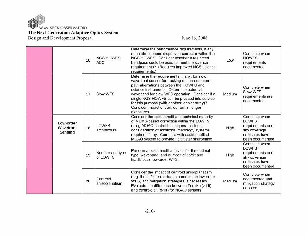
The Next Generation Adaptive Optics System Design and Development Proposal June 18, 2006
-210-
16 NGS HOWFS ADC
Determine the performance requirements, if any, of an atmospheric dispersion corrector within the NGS HOWFS. Consider whether a restricted bandpass could be used to meet the science requirements? (Requires improved NGS science requirements.)
Low
Complete when HOWFS requirements documented
17 Slow WFS
Determine the requirements, if any, for slow wavefront sensor for tracking of non-common-path aberrations between the HOWFS and science instruments. Determine potential waveband for slow WFS operation. Consider if a single NGS HOWFS can be pressed into service for this purpose (with another lenslet array)? Consider impact of dark current in longer exposures.
Medium
Complete when Slow WFS requirements are documented
18 LOWFS architecture
Consider the cost/benefit and technical maturity of MEMS-based correction within the LOWFS, using MOAO control techniques. Include consideration of additional metrology systems required, if any. Compare with cost/benefit of MCAO system to provide tip/tilt star sharpening.
High
Complete when LOWFS requirements and sky coverage estimates have been documented
19 Number and type of LOWFS
Perform a cost/benefit analysis for the optimal type, waveband, and number of tip/tilt and tip/tilt/focus low-order WFS.
High
Complete when LOWFS requirements and sky coverage estimates have been documented
Low-order Wavefront Sensing
20 Centroid anisoplanatism
Consider the impact of centroid anisoplanatism (e.g. the tip/tilt error due to coma in the low-order WFS) and mitigation strategies, if necessary. Evaluate the difference between Zernike (z-tilt) and centroid tilt (g-tilt) for NGAO sensors
Medium
Complete when documented and mitigation strategy adopted
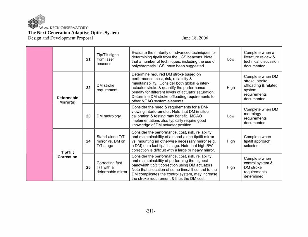
The Next Generation Adaptive Optics System Design and Development Proposal June 18, 2006
-211-
21 Tip/Tilt signal from laser beacons
Evaluate the maturity of advanced techniques for determining tip/tilt from the LGS beacons. Note that a number of techniques, including the use of polychromatic LGS, have been suggested.
Low
Complete when a literature review & technical discussion documented
22 DM stroke requirement
Determine required DM stroke based on performance, cost, risk, reliability & maintainability. Consider both global & inter-actuator stroke & quantify the performance penalty for different levels of actuator saturation. Determine DM stroke offloading requirements to other NGAO system elements
High
Complete when DM stroke, stroke offloading & related system requirements documented Deformable
Mirror(s)
23 DM metrology
Consider the need & requirements for a DM-viewing interferometer. Note that DM in-situe calibration & testing may benefit. MOAO implementations also typically require good knowledge of DM actuator position
Low
Complete when DM metrology requirements documented
24 Stand-alone T/T mirror vs. DM on T/T stage
Consider the performance, cost, risk, reliability, and maintainability of a stand-alone tip/tilt mirror vs. mounting an otherwise necessary mirror (e.g. a DM) on a fast tip/tilt stage. Note that high BW correction is difficult with a large or heavy mirror.
High Complete when tip/tilt approach selected
Tip/Tilt Correction
25 Correcting fast T/T with a deformable mirror
Consider the performance, cost, risk, reliability, and maintainability of performing the highest bandwidth tip/tilt correction using DM actuators. Note that allocation of some time/tilt control to the DM complicates the control system, may increase the stroke requirement & thus the DM cost.
High
Complete when control system & DM stroke requirements determined

The Next Generation Adaptive Optics System Design and Development Proposal June 18, 2006
-212-
26 Focus compensation
Consider cost/benefit of different approaches to focus compensation due to sodium layer motion. Include consideration of the proper combination of LGS focus, LOWFS focus and Slow WFS focus.
Medium
Complete when focus tracking strategy has been documented and reflected in error budgets Calibration
27 DM-lenslet registration
Evaluate the impact of DM-lenslet misregistration error for the high-order NGAO system. Consider having a rotator between DM & WFS, and having unavoidable latency in reconstructor updates.
Low
Complete when DM-lenslet registration requirements documented
Real-time Control 28 RTC
requirements
Evaluate the cost/benefit of direct vector-matrix-multiply (VMM) reconstruction algorithms vs. more numerically efficient techniques
Low
Complete when RTC requirements have been documented
Sodium Guide Star Laser
29 Laser pulse format
Consider the performance, cost, risk, reliability, and maintainability of different sodium laser pulse formats, including usability under various weather scenarios, infrastructure and beam transport issues, and commercial readiness.
High
Complete when laser pulse format requirements have been documented
Beam Transport 30 Laser beam
transport
Consider the performance, cost, risk, upgradability, reliability & maintainability of free-space guide star laser transport vs hollow core fiber transport
Medium
Complete when a beam transport system has been selected
Laser System
Projector System 31
LGS asterism geometry and size
Consider the technical performance tradeoff for different LGS asterism geometries (e.g. quincunx, ring, 1+triangle, or hex) and asterism radii. Include consideration of fixed or variable asterism radius in terms of optimizing Strehl of the tip/tilt stars and resulting sky coverage
High
Complete when LGS asterism, HO WFS, and LO WFS requirements have been documented.

The Next Generation Adaptive Optics System Design and Development Proposal June 18, 2006
-213-
32 Variable vs. fixed LGS asterism geometry
Consider the cost/benefit of continually varying the LGS asterism radius vs. a fixed number of radii (e.g. 5", 25", 50")
Medium
Complete when LGS asterism requirements have been documented
33 Quality of long exposures
Evaluate the unique considerations for enabling long science exposures (e.g., 1 hr). Note that visible-light & photon-starved IR IFU observations with NGAO will likely require longer exposures than today. The impact of mechanical, thermal & atmospheric changes should be understood.
Low
Complete when an analysis of the unique issues has been documented & incorporated into the NGAO requirements Operational
Tools Observing Scenarios
34 PSF calibration & prediction
Determine the functional requirements for on-line and off-line PSF calibration and prediction using internal NGAO telemetry and auxiliary data, such as an external real-time Cn
2(h) monitor.
Low
Complete when requirements for auxiliary systems for use with NGAO are documented
AO Enclosure 35 Reducing system
emissivity
Consider the performance, cost, risk, reliability & maintainability of cooling a Nasmyth NGAO enclosure. Calculate sensitivity impact as function of waveband (V through L-band)
High
Complete when enclosure operating temperature selected
Infra-structure
Keck Telescope 36 Telescope
wavefront errors
Improve our understanding of the actual primary mirror wavefront errors and NGAO ability to correct for them. Consider static &, more importantly, dynamical segment alignment & phasing errors. Determine the performance benefit of large LOWFS patrol field to enable use of the brightest possible NGS. Would a separate sensor outside the NGAO FoV be useful?
High
Complete when impact on current system documented & impact on NGAO reviewed
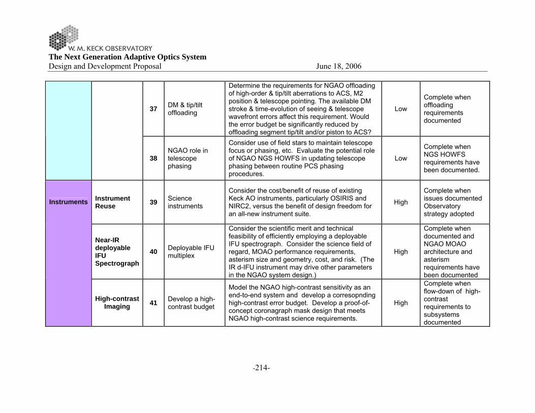
The Next Generation Adaptive Optics System Design and Development Proposal June 18, 2006
-214-
37 DM & tip/tilt offloading
Determine the requirements for NGAO offloading of high-order & tip/tilt aberrations to ACS, M2 position & telescope pointing. The available DM stroke & time-evolution of seeing & telescope wavefront errors affect this requirement. Would the error budget be significantly reduced by offloading segment tip/tilt and/or piston to ACS?
Low
Complete when offloading requirements documented
38 NGAO role in telescope phasing
Consider use of field stars to maintain telescope focus or phasing, etc. Evaluate the potential role of NGAO NGS HOWFS in updating telescope phasing between routine PCS phasing procedures.
Low
Complete when NGS HOWFS requirements have been documented.
Instrument Reuse 39 Science
instruments
Consider the cost/benefit of reuse of existing Keck AO instruments, particularly OSIRIS and NIRC2, versus the benefit of design freedom for an all-new instrument suite.
High
Complete when issues documented Observatory strategy adopted
Near-IR deployable IFU Spectrograph
40 Deployable IFU multiplex
Consider the scientific merit and technical feasibility of efficiently employing a deployable IFU spectrograph. Consider the science field of regard, MOAO performance requirements, asterism size and geometry, cost, and risk. (The IR d-IFU instrument may drive other parameters in the NGAO system design.)
High
Complete when documented and NGAO MOAO architecture and asterism requirements have been documented
Instruments
High-contrast Imaging 41 Develop a high-
contrast budget
Model the NGAO high-contrast sensitivity as an end-to-end system and develop a corresopnding high-contrast error budget. Develop a proof-of-concept coronagraph mask design that meets NGAO high-contrast science requirements.
High
Complete when flow-down of high-contrast requirements to subsystems documented

The Next Generation Adaptive Optics System Design and Development Proposal June 18, 2006
-215-
42 Mitigating segmentation effects for high-contrast
Identify approaches to mitigating primary-mirror segment effects on the high-contrast performance of NGAO (precision WFS, custom masks, etc.)
Low
Complete with high-contrast instrument requirements are documented

The Next Generation Adaptive Optics System Design and Development Proposal June 18, 2006
-216-
17 APPENDIX. RISK ASSESSMENT AND MITIGATION PLANS
Ref. # Description Severity
Probability 1st WAG Mitigation Plans
1 Achieving science requirements. a Long exposure time performance. Moderate Likely On instrument metrology b (add other parameters?)
2 Science requirements inadequately understood & changing. Major Likely Talk to the astronomers a lot
3
Delivered PSF too variable (spatially and temporally) to satisfy astrometry and photometry requirements Moderate Possible
4 Adequately meeting interferometer needs Unk Likely Review proposed performance with KI team
Rayleigh background on LGS WFS cannot calibrated out. Major Possible
Issue for GS MCAO, will be tested by them. Use long period pulsed laser and electronic shutter on HOWFS CCD to gate out Rayleigh
5 Wavefront error budget assumptions & accuracy
a
Bandwidth error assumptions. Assumption that closed loop bandwidth is 1/15 of sample rate. The rate of ~1/20 has been demonstrated, but would significantly impact error budget. Moderate Unlikely
Investigate and simulate control loop impact.
b Sodium return expectations not met Major Possible
Refine and adjust assumptions based on data from current systems
c 1e- CCDs for WFS. Major Possible Another design turn for CCID-56, more laser power
d Impact of telescope vibration. Moderate Possible Reduce telescope vibrations e Tomography. No sky demonstration.
i Codes contain assumptions that are untested in actual operating conditions Major Possible
Refine and adjust assumptions based on testing
ii Alignment and registration - beacons and WFS Major Likely
Design opto-mechanics for closed loop beacon positioning and stability. Implement test procedures during I&T to ensure proper alignment and registration.
g Tip/tilt tomography. No sky demonstration of benefits of multiple TT stars Moderate Unlikely
Rotating LGS constellation limits performance for long exposures Moderate Likely
De-rotate, configurable add beacons?
MCAO mirrors are not at proper conjigates or correct "statistical position" for the actual Cn^2 profile Moderate Possible
Get MASS/DIMM data for Mauna Kea before detailed design phase

The Next Generation Adaptive Optics System Design and Development Proposal June 18, 2006
-217-
6 Achieving contrast performance budget. Unk Possible (Need to verify science requirements)
7 Achieving defined photometry budget Unk Possible (Need to verify science requirements)
8 Achieving defined astrometry budget Unk Possible (Need to verify science requirements)
9 Achieving desired SNRs Unk Possible
Managing throughput in optical design, making provisions for long exposure stability
10 Achieving polarimetry requirement Unk Possible Control effects that rotate or scramble polarization
11 Risk of not being able to find adequate tip/tilt stars for certain science cases. Minor Likely
System provides gradual degradation, TT stars AO corrected
12 Fiber transport. Mitigation is conventional beam transport. Moderate Likely
Testing programs underway for fibers.
13 Availability of 65 actuator DM with 3.5 mm pitch with adequate stroke. Major Possible
Use 48 x 48, 5 mm, add a second DM
14 DM on a tip/tilt stage. Major Likely
DM incompatible with operation on TT stage Major Unlikely Use a separate TT mirror
Problems with DM interface cabling on TT stage Major Likely Address in DM design
Insufficient TT rejection Moderate Possible Add a second TT mirror 15 Switchyard approach:
a Dichroics. Size and performance. Major Likely
(at report we will not have this level of risk). Test coating samples to confirm performance before completing design
b Performance and reliability of dichroic changers. Moderate Unlikely
16 K-mirror. Size, performance. Moderate Possible Other architectures for derotation, better coatings
17 Achieving real-time control performance requirements Major Possible
Benchmark tests, simiulations anchored to RTC hardware performance, prototype testing
18 Fitting system on telescope. Major Unlikely Design process will ensure compatible system
19 Thermal/mechanical performance of AO system environmental enclosure. Moderate Unlikely
Careful design, thermal performance modeling including FEA.
20 Design & cost of interfacing with existing instruments exceeds value of doing so Unk Possible Replace those instruments
21 Availability of required lasers. Major Likely Continue to pursue laser development
22 MOAO not demonstrated. Moderate Likely
MCAO gives reasonable sky coverage, VILLAGES testing planned. Other testing

The Next Generation Adaptive Optics System Design and Development Proposal June 18, 2006
-218-
programs, perhaps on existing Keck AO system.
23 Fast LOWFS IR (SNAP) based camera.
Detector performance Moderate Possible Some performance data on hand. Testing continues.
Detector availability Major Unlikely Two sources of supply 24 Calibration unit with LGS simulators.
a Finding space for it Major Possible
Will be designed in from the beginning as an essential capability
b Achieving required level of performance Moderate Possible On-sky calibration can substitute at greater expense.