the neumann am-32b master stereo disk recording · pdf file2 west 46th street, new york 36,...
TRANSCRIPT

2 WEST 46th STREET , NEW YORK 36 , NEW YORK
THE NEUMANN AM-32b MASTER STEREO DISK RECORDING LATHE
GENERAL:
It has been s ome time since the design of an entirely new disk lathe has come to the fore. Now with stereo disk placing even greater demands on the manufactur er - demands for quality and quantity - it is time to re-evaluate the entire line of equipment used in the production and r e production of stereophonic records. One important link to date has been ignored: the disk cutting lathe itself. Reason for placing renewed emphasis on the lathe is the advent (or should we say lire-advent") of vertical compliance in cartridges, which demands of the disk even more rumble-fre e performance than he retofore. Secondly, the complex excursions of the groove have made it necessary to reduce the amount of time possible on a disk, making an investigation into the possibilities of ~~~ ~a~~~~l!.s~!:'''0.!i~!!'yg~~ Furthermore, since the hazards of Stereo are considerably more than double those of monophonic recor ding, further automation of the actual cutting process has be come essential.
A. THE TURNTABLE UNIT - AM 32b:
The basic lathe bed is built up on a heavy cast iron base, standing on four rubber shock mountings. The turntable itself is of heavy cast iron, weighing 65 lbs. Its edge is cas t with three' stroboscopic rings - one for each speed -which are illuminated by a small neon spotlight bulb for easy observation. The turntable is completely isolated from the drive below by means of an: oil-filled coupling, preventing rumble and flutter from being transmitted from the drive. The turntable is driven solely by a film of oil between two walls of two concentric cylinders. Almost a pint of oil goes into this coupling. The lathe bed is of the slide type with two ball bearings riding the top of the bed to re,lieve the strain placed on the sled by the weight of the cutter suspension and cutterhead.
Directly beneath the lathe bed is a calibrated diameter scale on which are mounted the starting cams and end groove stop. Three cams, for 7", 10", and 12" disks are provided, the one to be used being raise d into operating position. 'The end groove stop is adjustable to the three standard RIAA end groove diameters, and causes the cutterhead either to lift immediately (for eccentric grooves), or with a 1. 25 revolution delay to provide a locked groove (now becoming standard for LP as well). The lead-screw engaging l ever is interlocked in such a way that the cutter will lift at any time that it is not being driven by the lead-screw, making stylus catastrophies impossible .

Page 2"
This motor, manufactured by LYREC of Copenhagen, Denmark, is tmique in its field. It is of the synchronous type with motor RPM equal to disk RPM . A gear-like wheel, about 10 inches in diameter, rotates inside a similar inside gear in which, by means of a winding, a rotating magnetic field is set up. The motor must be started (for which a starting motor is mounted atop the tmit) and require s a flywhee l (the turntable) to continue ''hunting'' from one gear-tooth to the next. Since this type of motion has some inherent flutter, a second gear is placed next to the first, but out of phase. The winding for this gear is phase advanced by insertion of a condenser producing a 90 degree phase shift, and cutting the flutter in half. For each speed, 33, 45, and 78, there are two such gears and they are all arranged coaxially on the drive shaft. In this way, each speed has its own motor. Wow and flutter of the lathe is in the neighborhood of 0.0080/. RMS total, at ALL speeds. The motor is connected to the turntable by a connecting rod with two simple rubber disk couplings . Alignment of the connecting rod is not critical . The ~onnecting rod is extendable to suit any console height.
C. 16-2/3 RPM CONVERTER - ZA 33:
This small 4" x 4" X 5" unit containing a selenium rectifier, reduces the 33-1/3 RPM speed m otor to 16-2/3 by doubling the ripple of the rotating magnetic field. For experimental uses, this tmit will also produce the half-speeds of 45 or 78 RPM, useful for cutting frequency response disks and the like. For those interested in the reverse cutting of disks, incidentally, the motor can, of course, rotate in either direction in synchronism, depending on the direction in which it is initially started.
D. 16 1/2" Vacuum-chuck Turntable - ZA 3:
This unit fits over the basic turntable of the AM 32b and provides vacuum hold-down for all size blanks from 10" to 17-1/4". A disabling valve provides the correct group of hole s for any given size lacquer disk, with vacuum, thus preventing air escape and hiss.
Eccentric Cutting: The vacuum hold-down turntable can be displaced by simple pressure against one side, so that eccentric and grooves can be cut right on the lathe itself . A calibrated stop sleeve which fits over the end groove stop pin makes it unnecessary to examine the meeting of the eccentric groove with the tail-out groove under a microscope; the meeting is accurate automa tically.
E. THE CUTTERHEAD SUSPENSION - SA 32; Part of AM 32b:
All of the cutterhead connections and functions are accomplished by a rectangular device mounted on the lathe's transport sled. The cutter is plugged into this tmit by means of a small metal plug attached to it, permitting exchange of cutters from monophonic to stereo without misalignment. The connections are made by means of two 6-prong plugs on the suspension. These provide the two drive signals, two fee dback signals, and DC stylus heat. Both the heating current and the two input signals are switched off when the cutter is
.,

• Page 3
raised. A release solenoid immediately raises the cutterhead whenever the "stop" button is depressed, when the sled hits the end groove stop, or when the lead screw is disengaged,
A dash-pot at the front of the suspension is equipped with a perforated piston. An adjustable shield over these perforations allows a wide range of damping effectf' without changing viscosity of fluid.
The wiring from the cutter is led concentrically through the pivot ball bearings to prevent any stiffness or resistance to free motion. The tilting mechanism to which the cutter is mounted is connected to a large moving coil system which, together with the depth-of-cut control provides electronic depth variation.
F. DEPTH-OF-CUT CONTROL PANEL - TE 2; Part of AM 32b:
Located on the base of the lathe bed is the depth-of-cut control panel. It supplies a DC current to the moving coil system in the cutter suspension which relieves cutterhead pressure on the disk. A simple potentiometer provides full range of cutting depth, which can be observed in the microscope while adjust ment is made. A second, similar control pre-sets the increased depth generally used in lead in, lead out and spiraling grooves. A test button switches to the second pre-set control for proper adjustment prior to commencement of cutting operation. Two toggle switches permit automatic deepening of the grooves during spiraling, lead in or lead out, or disables it for anyone of these functions.
G. THE PITCH CONTROL UNIT - VA 32a:
The pitch control and general control consolette is a separate piece of equipment, and is situated next to the lathe to its right. NO power or drive is taken from the turntable motor for any drive of the lead screw; the pitch drive is entirely self-contained, and is coupled to the lead screw by a four-way shock isolated coupling. The console mounts the following controls: motor stop and start; motor speed control selector; heated stylus control (D. C. ); stop; start; lead in; spiraling; lead out buttons and tally lights; heated stylus ammeter; micro scope light switch; cutterhead pick up delay for concentric and groove; main pitch selection dial; and pitch control current meter. The depth of cut control current meter is mounted on the base of the lathe itself.
The pitch motor is connected by means of a belt and through an oil filled gear train and the flexible coupling to the lead screw. A copper disk on the shaft of this motor runs over the four poles of an electromagnet, in which a DC current produces a braking action which stabilizes the pitch motor's RPM. A second, identical motor is likewise belt connected to an overdrive in the gear train, and serves for speed up of pitch for lead in, spiraling, and lead out . It likewise has a stabilizing brake by means of which the lead in, spiraling and lead out pitch can be separately and accurately adjusted at each speed. The braking current on the pitch motor is apprOximately 100 ma, which is supplied from an internal rectifier . The main pitch selector control which is calibrated from 54 to 475 lineS / inch, is simply a powerstat controlling the AC voltage fed to the pitch drive motor.

Page' 4
* H. THE AUTOMATIC PITCH AMPLIFIER - SV 32s:
In the rack space inside the base of the lathe are located three servo amplifiers required for stereodisk cutting control. The first of these is the SV 32s pitch control amplifier . A preview head is required for automatic control, and in this c~se, the head must be a stereo head. The signal from this head is fed to two tape playback amplifiers, and from there to a sum and difference transformer converter.
In the 45/45 stereo system, the phasing is so arranged that the sum
of the two stereo signals forms the lateral-only component of the groove, while the difference of the signals is the purely vertical component. In order to separate the signals influencing the excursion of the stylus in a lateral plane, we must, therefore, add the two signals from the stereo preview head, and control with this sum the variation·-of pitch in order to attain maximum space utilization. This addition is now fed to the input of the pitch control amplifier.
In this amplifier, the signal is rectified and fed to an RC time constant circuit. A second rectifier leads to a second RC time constant circuit of shorter duration. A diode between the two RC circuits becomes conductive whenever the voltage of one of them falls below that of the other. This is so arranged that it will occur after one full revolution of the disk. Should no further signal be received from the preview head by that time, the resulting negative voltage is applied to the power output stage of the amplifier which delivers the necessary braking current needed by the pitch control motor, and that braking current, which was partially removed during the period of high input signal, is restored to normal, and the lead screw drive is again slowed down to the pitch adjusted on the main dial. The disk speed (time constant) as we ll as the pitch control range has to be adjusted on the amplifier. Since the pitch control is entire ly electronic, it is fast acting, thus achieving optimum space conservation.
* 1. THE DEPTH CONTROL AMPLIFIER - SV 32v:
The depth control amplifier SV 32v is in every detail identical to the pitch control unit. its output, however, is fed to the solenoid in the cutter suspension, and produces there the varying relief of cutter pressure, acting against the weight and counterbalancing spring of the cutter. The time constants required are the same as in pitch control.
" J. THE INTEGRATION AMPLIFIER - SV 32t:
"
In lateral and vertical modulation, increased depth requires in·· creased pitch, so that any deepening of the groove allowed by the depth control amplifier, must be translated in turn into increased pitch at the same time (but not conversely). The SV 32t integration amplifier does just that, by adding to the pitch control current whenever increased depth is called for. This unit is a simple rectifier circuit without time constants, since these are already taken care of by the other two control units .
It has been shown over the past year and a half that this form of independent pitch and depth control can add up to 6 minutes to the playing time of one side of a 12" LP recording. Of course, as is always the case, recordings

Page 5
of a high dynamic range benefit most from such controls, while highly limited or compressed material gains almost nothing.
Each of the control amplifiers is equipped with a plug- in equalizer for RIAA equalization, which translates the RIAA pre - ehphasized velocity curve into its counterpart in stylus excursion. As such, both depth and pitch control are most active when low frequency signals are received, while high frequency sound of even the highest inte nsity produces practically no increased depth or pitch.
" Protected under one or more of the following German patents: 836,116; 938,586; 845,413; 875,732; 1,013,889. U. S. patents pending.
K. PHOTOELECTRIC AUTOMATION UNIT - ZA 34:
Each AM 32b Stereo Disk Mastering Lathe comes equipped with a unit for the complete automation of the mastering process. A photocell placed on the tape playback machine directly after the head assembly s ignals to this unit when ever leader tape (or a light mark painted on the back of the tape at the end of each cut) comes by. On the unit itself, the operator has punched up on a series of 12 push buttons, the number of cuts the master i s to have. On another row of 12 push buttons he selects the length of the spiral between cuts from 0.5 to 5.5 seconds in .5 second increments. The unit will then automatically signal to the lathe to spiral (with increased depth of cut) at the beginning of the first piece of leader. If desired, another button permits the lathe to spiral for the entire length of the leader tape, where such has been timed. As each cut is ended, a selector is stepped and the next numbered cut button lights up. At the last cut, a red lamp signals that the next leader or mark will produce the lead out spiral and either immediate cutter lift or concentric groove .and lift.
L. THE MICROSCOPES - ZA 36 :
A high power precision "Leitz Ultra Pak" microscope with concentric illumination and micrometer focusing, provides the clearest possible picture of the groove. It comes with multi- color light filters and blanking filters, making it possible to examine either half of the groove separately. The microscope is mounted at right angles to the disk surface for proper inspection, and moves exactly along its radius. A second, small microscope is attached to the cutterhead sus pension unit and is transported with it, permitting observation of the last few grooves "standing still" as y<;JU cut. Lighting is also provided for this microscope. Both have reticle lines for calibration.
M . THE BUCHMANN MEYER LIGHT - Z 21: ------------------------- ----
One of the great aids to frequency response alignment is the Buchmann Meyer light; a parallel light source which is to be mounted on the ceiling to the left of the turntable, so as to throw a beam at the disk at a 45 degree angle. In this way, it is only necessary to cut a band of 1000 cycle tone, followed by one of 15 KC. Then, while observing the light band width of the 15 KC tone, the equalization is adjusted until the 1 KC and 15 KC widths are equal (equalization flat).
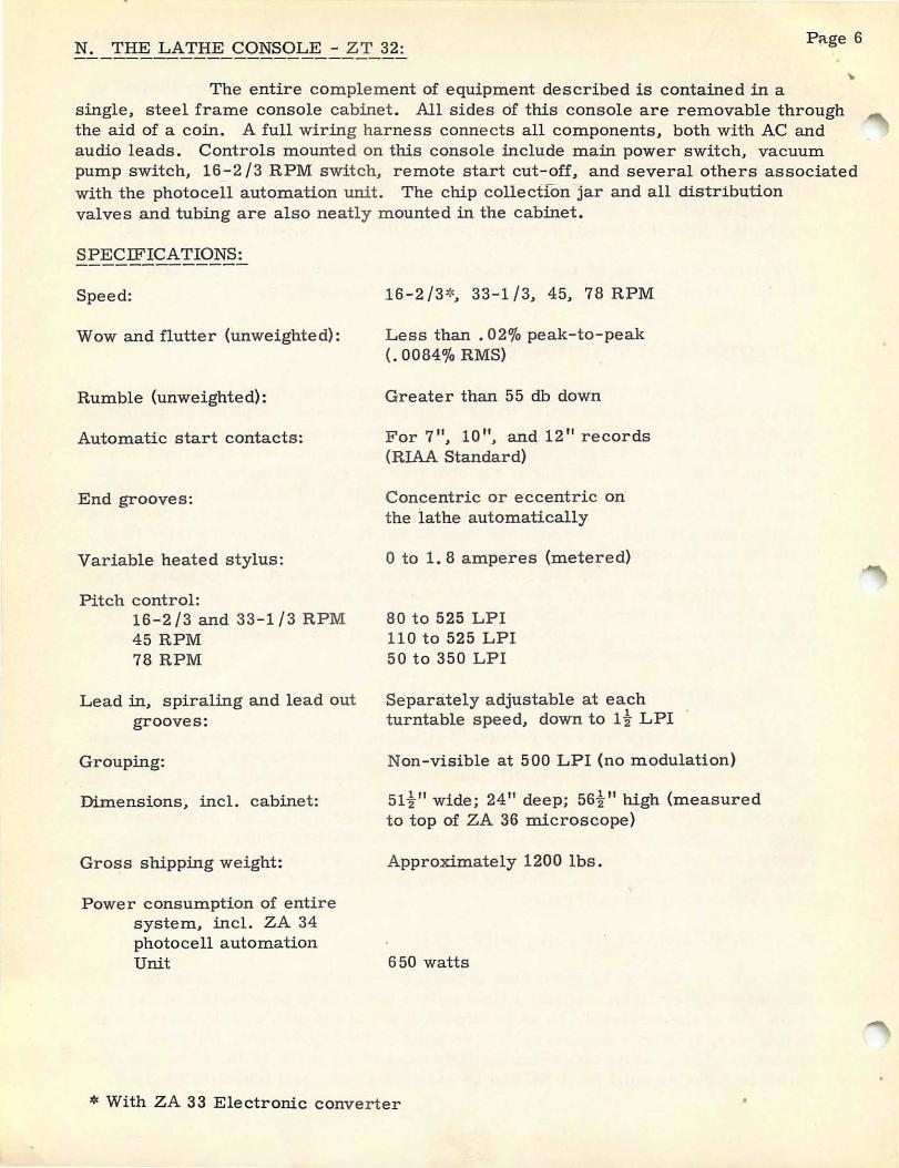
N. THE LATHE CONSOLE - ZT 32: PRge 6
The entire complement of equipment described is contained in a single, steel frame console cabinet. All sides of this console are removable through the aid of a coin. A full wiring harness connects all components, both with AC and audio leads. Controls mounted on this console include main power switch, vacuum pump switch, 16-2/3 RPM switch, remote start cut-off, and several others associated with the photocell automation unit . The chip collectRm jar and all distribution valves and tubing are also neatly mounted in the cabinet.
SPECIFICATIONS:
Speed:
Wow and flutter (unweighted):
Rumble (unweighted) :
Automatic start contacts:
End grooves:
Variable heated stylus:
Pitch control: 16-2/3 and 33-1/3 RPM 45 RPM 78 RPM
Lead in, spiraling and lead out grooves:
Grouping:
Dimensions, incl. cabinet:
Gross shipping weight:
Power consumption of entire system, incl. ZA 34 photocell automation Unit
16-2/3*, 33-1/3, 45, 78 RPM
Less than. 02"10 peak-to-peak (.0084"10 RMS)
Greater than 55 db down
For 7", 10 ", and 12" records (RIAA Standard)
Concentric or eccentric on the lathe automatically
o to 1. 8 amperes (metered)
80 to 525 LPI 110 to 525 LPI 50 to 350 LPI
Separately adjustable at each turntable speed, down to 1 t LPI
Non-visible at 500 LPI (no modulation)
51t" wide; 24" deep; 56t" high (measured to top of ZA 36 microscope)
Approximately 1200 lbs.
650 watts
* With ZA 33 Electronic converter
• Page 7
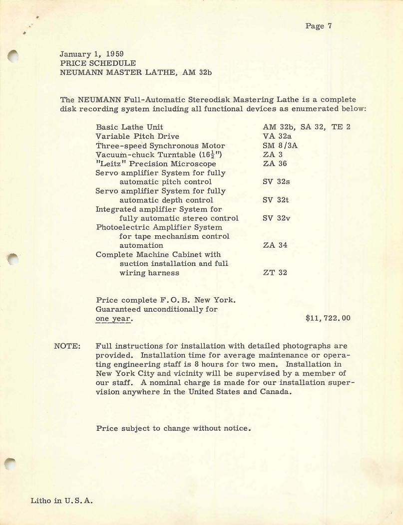
January 1, 1959 PRICE SCHEDULE NEUMANN MASTER LATHE, AM 32b
The NEUMANN Full-Automatic Stereodisk Mastering Lathe is a complete disk recording system including all functional devices as enumerated below:
NOTE:
Basic Lathe Unit Variable Pitch Drive Three-spee"d Synchronous Motor Vacuum-chuck Turntable (16t") "i'Leitz" Precision Microscope Servo amplifier System for fully
automatic pitch control Servo amplifier System for fully
automatic depth control Integrated amplifier System for
fully automatic stereo control Photoelectric Amplifier System
for tape mechanism control automation
Complete Machine Cabinet with suction installation and full wiring harness
Price complete F. O. B. New York. Guaranteed unconditionally for
£~_l..e~E..
AM 32b, SA 32, TE 2 VA 32a SM 8/3A ZA 3 ZA 36
SV 32s
SV 32t
SV 32v
ZA 34
ZT 32
$11,722.00
Full instructions for installation with detailed photographs are provided. Installation time for average maintenance Qr operating engineering staff is 8 hours for two men. Installation in New York City and vicinity will be supervised by a member of our staff. A nominal charge is made for our "installation supervision anywhere in the United States and Canada.
Price subject to change without notice.
Litho in U.S.A.