the networker’s guide to appletalk, ipx, and...
TRANSCRIPT
The Networker’s Guide toAppleTalk, IPX, and
NetBIOS
3
UNTIL THE EARLY 1990S,TCP/IP WAS REALLY ONLY PREVALENT in large govern-ment and research facilities where UNIX and other supercomputing operating systemsused it as a common network communications protocol.When PCs came into thepicture, they were not networked. Rather, they were used either as front-ends to bigmicro or mainframe systems (IBM was a big fan of this approach) or as standalone sys-tems. In the early 1980s, as PCs grew in number and in performance, three strategiesemerged to provide PCs with networking services:AppleTalk, Novell NetWare, andIBM’s NetBIOS.
The goal of this chapter is to give you an understanding of the various protocolsthat make up the protocol suites and the roles they perform. It is not intended toexplain how to design, set up, and manage a network. Chapter 7,“Introduction toCisco Routers,” and Chapter 10,“Configuring IP Routing Protocols on CiscoRouters,” discuss configuration issues for these protocols. Because NetBIOS is a ses-sion layer protocol rather than a protocol suite, it will be described in the context ofits operational behaviors at the end of this chapter.
03 9777 CH03 5/21/01 3:42 PM Page 85

86 Chapter 3 The Networker’s Guide to AppleTalk, IPX, and NetBIOS
AppleTalkAppleTalk was an outgrowth of the Apple Macintosh computing platform. First intro-duced in 1984 and updated in 1989, it was designed to provide the Macintosh with acohesive distributed client/server networking environment.AppleTalk, like theMacintosh, is a “user friendly” network operating system (NOS).All the actual com-munication operations are masked from the user.To facilitate this,AppleTalk incorpo-rates a dual network identity structure, both operationally and contextually.Theoperational structure uses binary network addressing to represent network segments,end-nodes, and network services (such as file transfer, printing, and so on).The con-textual structure uses names and logical groupings, called zones, as the user interfacefor addressing network visible entities (NVEs).The contextual structure functions like a mask, covering the actual physical network infrastructure.This provides the net-work administrator with the ability to group users and network services into logicalgroupings instead of physically segmenting the network to achieve the same effect.Figure 3.1 illustrates this concept.
Zone: Sales and Marketing
Zone: Research
Cable Range 35–38
Cable Range 99–101Zone: Accounts PayableZone: PurchasingZone: Billing
}Logical
}Logical
}Physical
}
Physical
Figure 3.1 Physical versus logical AppleTalk network segmentation.
All AppleTalk network service interactions are based on a client/server model. Clientsare the end-nodes requesting the service; servers are the end-nodes providing the service.The protocols that provide the services for the operational identity structureare provided on OSI-RM Layers 1, 2, 3, and 4. Contextual services are provided onLayers 4 and 5.
03 9777 CH03 5/21/01 3:42 PM Page 86

87AppleTalk
AppleTalk Phase 1 and Phase 2There are two flavors of AppleTalk network: AppleTalk Phase 1 and AppleTalk Phase2.The Phase 1 network approach is oriented toward interconnecting workgroups.Phase 1 supports a limited network diameter of a single network segment containingno more than 127 clients and 127 servers. Phase 1 networks use a single networknumber (0) for the entire physical network.
Phase 2 networks support multiple logical networks over the same cable segment.Each logical network supports up to 253 clients or servers.To maintain compatibilitywith Phase 1 networks and provide support for multinetwork cable segments, Phase 2supports two different network configurations: nonextended and extended.With Phase2, an AppleTalk logical network is defined by its cable range.The cable range is the net-work number or numbers used by the end-nodes connected to the transmissionmedia. Each AppleTalk cable range supports 253 hosts.The size of the cable rangedetermines the number of hosts that can be connected on the media simultaneously.
The cable range is a number range or contiguous sequence of numbers from 1 to64,000, expressed in a start-end format.The size of the cable range determines if thenetwork is a nonextended or extended type.A nonextended Phase 2 network uses asingle cable range (to maintain compatibility with the Phase 1 network structure) andcan support 253 connected users; 60001-60001 is an example of a nonextended Phase2 network.The start and end range are the same number.An example of an extendedcable range would be 60001-60011.With this range, 253 hosts can be supported oneach range, so theoretically, 2,530 end-stations could be connected to this media seg-ment.As you can see, the main advantage of extended over nonextended is theamount of hosts that can be supported over a single cable segment.
There are some compatibility issues between Phase 1 and Phase 2 networks, so it isbest to use Phase 2, if possible.The major incompatibilities are with Phase 1 and Phase2 EtherTalk (AppleTalk’s Ethernet implementation), and with using Phase 1 and Phase 2 extended networks together. EtherTalk Phase 1 and Phase 2 use differentframe formats and are not compatible.
It is possible to run Phase 1 and Phase 2 over the same Ethernet cable, but theycannot exchange data with each other without a router. Phase 1 networks and Phase 2extended networks also cannot interoperate because Phase 1 cannot understandextended cable ranges. If you need to use Phase 1 and Phase 2 together, use nonex-tended Phase 2 networks.
AppleTalk operates over all the IEEE and ANSI Layer 2 protocols and WAN (bothpoint-to-point and dial-on-demand configurations) transports.Apple Computer hasalso defined its own transport media specification known as LocalTalk. LocalTalk is aproprietary network architecture, left open to development by any vendor, as long asinterpretability and standards compliance is assured.
03 9777 CH03 5/21/01 3:42 PM Page 87

88 Chapter 3 The Networker’s Guide to AppleTalk, IPX, and NetBIOS
Figure 3.2 The AppleTalk protocol suite compared with the OSI-RM.
AppleTalk Layers 1 (Physical) and Layer 2 (Data Link)AppleTalk supports four LAN media access implementations: LocalTalk, EtherTalk,TokenTalk, and FDDITalk.These implementations are supported over most WANpoint-to-point access protocols.AppleTalk also uses AppleTalk Address ResolutionProtocol (AARP) to manage Layer 3 AppleTalk network address to network hardwarecontroller address translation.
AppleTalk Node Addressing
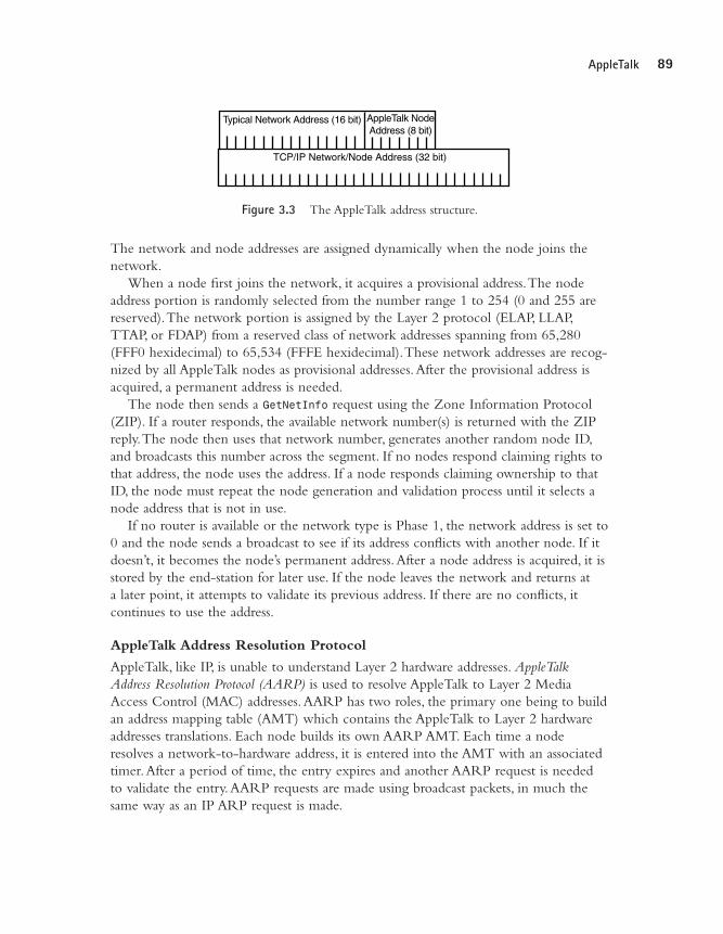
All AppleTalk clients and servers require a unique AppleTalk address to participate onthe network (see Figure 3.3).The network address is 24-bits long and consists of a 16-bit network address and an 8-bit node address. Unlike most network protocols, how-ever,AppleTalk does not require that nodes have a preconfigured address. Instead, thenode acquires an address when it first accesses the network.
Application
Presentation
Session
Transport
Network
Data Link
Physical
OSI-RM
AppleTalkFilingProtocol (AFP)
PostScript
AppleTalkSessionProtocol (ASP)
Routing TableMaintenanceProtocol (RTMP)
AppleTalk DataStream Protocol(ADSP)
AppleTalk TransactionProtocol (ATP)
AppleTalk EchoProtocol (AEP)
Name BindingProtocol(NBP)
Printer AccessProtocol(PAP)
ZoneInformation Protocol (ZIP)
EtherTalk TokenTalk LocalTalk FDDITalk
Datagram Delivery Protocol (DDP)
03 9777 CH03 5/21/01 3:42 PM Page 88
89AppleTalk
Figure 3.3 The AppleTalk address structure.
The network and node addresses are assigned dynamically when the node joins thenetwork.
When a node first joins the network, it acquires a provisional address.The nodeaddress portion is randomly selected from the number range 1 to 254 (0 and 255 arereserved).The network portion is assigned by the Layer 2 protocol (ELAP, LLAP,TTAP, or FDAP) from a reserved class of network addresses spanning from 65,280(FFF0 hexidecimal) to 65,534 (FFFE hexidecimal).These network addresses are recog-nized by all AppleTalk nodes as provisional addresses.After the provisional address isacquired, a permanent address is needed.
The node then sends a GetNetInfo request using the Zone Information Protocol(ZIP). If a router responds, the available network number(s) is returned with the ZIPreply.The node then uses that network number, generates another random node ID,and broadcasts this number across the segment. If no nodes respond claiming rights tothat address, the node uses the address. If a node responds claiming ownership to thatID, the node must repeat the node generation and validation process until it selects anode address that is not in use.
If no router is available or the network type is Phase 1, the network address is set to0 and the node sends a broadcast to see if its address conflicts with another node. If itdoesn’t, it becomes the node’s permanent address.After a node address is acquired, it isstored by the end-station for later use. If the node leaves the network and returns at a later point, it attempts to validate its previous address. If there are no conflicts, it continues to use the address.
AppleTalk Address Resolution Protocol
AppleTalk, like IP, is unable to understand Layer 2 hardware addresses. AppleTalkAddress Resolution Protocol (AARP) is used to resolve AppleTalk to Layer 2 MediaAccess Control (MAC) addresses.AARP has two roles, the primary one being to buildan address mapping table (AMT) which contains the AppleTalk to Layer 2 hardwareaddresses translations. Each node builds its own AARP AMT. Each time a noderesolves a network-to-hardware address, it is entered into the AMT with an associatedtimer.After a period of time, the entry expires and another AARP request is neededto validate the entry.AARP requests are made using broadcast packets, in much thesame way as an IP ARP request is made.
Typical Network Address (16 bit) AppleTalk NodeAddress (8 bit)
TCP/IP Network/Node Address (32 bit)
03 9777 CH03 5/21/01 3:42 PM Page 89
90 Chapter 3 The Networker’s Guide to AppleTalk, IPX, and NetBIOS
It is also possible to update the AMT by reading the hardware and networkaddresses on incoming data packets.This is known as address gleaning.This process hasan associated packet processing cost, however, so it is not widely used in end-stations,but rather on routers where it is incorporated into the packet handling process.Address gleaning is helpful in terms of network performance because it reduces AARPrequests.
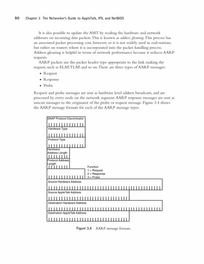
AARP packets use the packet header type appropriate to the link making therequest, such as ELAP,TLAP, and so on.There are three types of AARP messages:
n Requestn Responsen Probe
Request and probe messages are sent as hardware level address broadcasts, and areprocessed by every node on the network segment.AARP response messages are sent asunicast messages to the originator of the probe or request message. Figure 3.4 showsthe AARP message formats for each of the AARP message types.
SNAP Protocol Discriminator
Hardware Type
Protocol Type
Hardware Address Length
Protocol Address Length
Function1 = Request2 = Response3 = Probe
Source Hardware Address
Source AppleTalk Address
Destination Hardware Address
Destination AppleTalk Address
Figure 3.4 AARP message formats.
03 9777 CH03 5/21/01 3:42 PM Page 90
91AppleTalk
The second role of AARPs is to assist in the address acquisition process.When thenode asks Layer 2 for a network address, a random provisional address is chosen andthen checked against entries in the AMT. If the address is not in its AMT, the hostAARPs for it. If the address is not in use, the provisional address is used and theaddress acquisition process continues.
LocalTalk
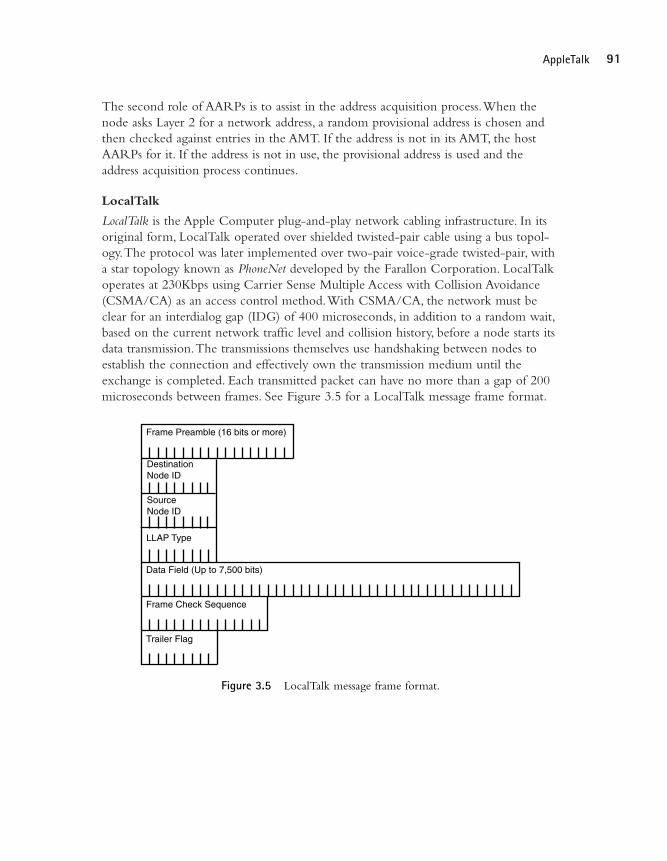
LocalTalk is the Apple Computer plug-and-play network cabling infrastructure. In itsoriginal form, LocalTalk operated over shielded twisted-pair cable using a bus topol-ogy.The protocol was later implemented over two-pair voice-grade twisted-pair, witha star topology known as PhoneNet developed by the Farallon Corporation. LocalTalkoperates at 230Kbps using Carrier Sense Multiple Access with Collision Avoidance(CSMA/CA) as an access control method.With CSMA/CA, the network must beclear for an interdialog gap (IDG) of 400 microseconds, in addition to a random wait,based on the current network traffic level and collision history, before a node starts itsdata transmission.The transmissions themselves use handshaking between nodes toestablish the connection and effectively own the transmission medium until theexchange is completed. Each transmitted packet can have no more than a gap of 200microseconds between frames. See Figure 3.5 for a LocalTalk message frame format.
Frame Preamble (16 bits or more)
DestinationNode ID
SourceNode ID
Data Field (Up to 7,500 bits)
Frame Check Sequence
Trailer Flag
LLAP Type
Figure 3.5 LocalTalk message frame format.
03 9777 CH03 5/21/01 3:42 PM Page 91
92 Chapter 3 The Networker’s Guide to AppleTalk, IPX, and NetBIOS
Layer 2 transport is handled by the LocalTalk Link Access Protocol (LLAP). LLAPprovides “best effort” transport service and uses the node and network numbers forsource and destination addressing so no hardware-to-network address resolution ser-vice is required.Addressing is assigned dynamically.When a host joins a network, itgenerates a random network number that it broadcasts to the network for validation. Ifthe address is not in use, the node uses it. If the address is in use, the node generatesanother address and validates again until it finds an address it can use. LocalTalk’s busimplementation network diameter is limited to a 300-meter total cable distance withno more than 32 active nodes. PhoneNet supports longer span distances, but is stilllimited to 32 active nodes a segment. LocalTalk has no extended Phase 2 support; ifit’s used with other media (EtherTalk,TokenTalk, and so on), a router or translationbridge is required.
EtherTalk
EtherTalk provides collision-based access control (using CSMA/CD) over 10Mbps and100Mbps Ethernet with EtherTalk Link Access Protocol (ELAP). ELAP handles all theAppleTalk Upper Layer Protocols (ULPs) interaction with the transmission medium.The version of AppleTalk used (Phase 1 or Phase 2) determines how the EtherTalkframe is formatted.AppleTalk version 1 uses the Ethernet-II frame specification.AppleTalk version 2 uses the IEEE 802.3 SNAP (Subnetwork Access Protocol) framespecification.AppleTalk protocols do not understand Layer 2 hardware addresses.ELAP uses AARP for determining proper frame source and destination addressing.
It is possible to operate clients and servers on the same media segment using bothPhase 1 and Phase 2 packets. However, types 1 and 2 frame types are only recognizedby similar clients, so a translation router must be installed if the networks need toexchange data with one another. ELAP transmits data bytaking the client destinationaddress from the DDP datagram, performing an AARP address mapping table lookup,then constructing the Ethernet frame appropriate to the network: Ethernet 2 forAppleTalk Phase 1 or 802.3 SNAP for AppleTalk Phase 2.
NoteEthernet, Token Ring, and FDDI Layer 2 protocols are all covered in detail in Chapter 4, “LAN
Internetworking Technologies.” The discussion that follows does not require an extensive knowledge of
these protocols, but you might want to skip ahead if you have questions.
03 9777 CH03 5/21/01 3:42 PM Page 92
93AppleTalk
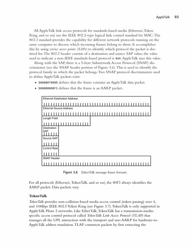
All AppleTalk link access protocols for standards-based media (Ethernet,TokenRing, and so on) use the IEEE 802.2-type logical link control standard for MAC.The802.2 standard provides the capability for different network protocols running on thesame computer to discern which incoming frames belong to them. It accomplishesthis by using service access points (SAPs) to identify which protocol the packet is des-tined for.The 802.2 header consists of a destination and source SAP value; the valueused to indicate a non-IEEE standards-based protocol is $AA.AppleTalk uses this value.
Along with the SAP, there is a 5-byte Subnetwork Access Protocol (SNAP) dis-criminator (see the SNAP header portion of Figure 3.6).This is used to identify theprotocol family in which the packet belongs.Two SNAP protocol discriminators usedto define AppleTalk packets exist:
n $080007809B defines that the frame contains an AppleTalk data packet.n $00000080F3 defines that the frame is an AARP packet.
Ethernet Destination Address
Ethernet Source Address
Length Field
DestinationSAP
Source SAP
Control Byte
SNAP Header
Figure 3.6 EtherTalk message frame formats.
For all protocols (Ethernet, TokenTalk, and so on), the 80F3 always identifies theAARP packet. Data packets vary.
TokenTalk
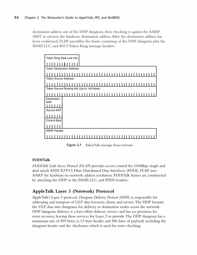
TokenTalk provides non-collision-based media access control (token passing) over 4,and 16Mbps IEEE 802.5 Token Ring (see Figure 3.7).TokenTalk is only supported inAppleTalk Phase 2 networks. Like EtherTalk,TokenTalk has a transmission-media-specific access control protocol called TokenTalk Link Access Protocol (TLAP) that manages all the UPL interaction with the transport and uses AARP for hardware-to-AppleTalk address translation.TLAP constructs packets by first extracting the
03 9777 CH03 5/21/01 3:42 PM Page 93
94 Chapter 3 The Networker’s Guide to AppleTalk, IPX, and NetBIOS
destination address out of the DDP datagram, then checking it against the AARPAMT to retrieve the hardware destination address.After the destination address hasbeen confirmed,TLAP assembles the frame consisting of the DDP datagram plus theSNAP, LLC, and 802.5 Token Ring message headers.
Token Destination Address
Token Source Address
Token Source Routing Info (Up to 144 bytes)
Token Ring Data-Link Info
DestinationSAP
Source SAP
Control Byte
SNAP Header
Figure 3.7 TokenTalk message frame formats.
FDDITalk
FDDITalk Link Access Protocol (FLAP) provides access control for 100Mbps single anddual attach ANSI X3T9.5 Fiber Distributed Data Interfaces (FDDI). FLAP usesAARP for hardware-to-network address resolution. FDDITalk frames are constructedby attaching the DDP to the SNAP, LLC, and FDDI headers.
AppleTalk Layer 3 (Network) ProtocolAppleTalk’s Layer 3 protocol, Datagram Delivery Protocol (DDP), is responsible foraddressing and transport of ULP data between clients and servers.The DDP formatsthe ULP data into datagrams for delivery to destination nodes across the network.DDP datagram delivery is a best-effort delivery service and has no provision for error recovery, leaving these services for Layer 2 to provide.The DDP datagram has amaximum size of 599 bytes (a 13-byte header and 586 bites of payload) including thedatagram header and the checksum, which is used for error checking.
03 9777 CH03 5/21/01 3:42 PM Page 94
95AppleTalk
AppleTalk Sockets
All AppleTalk network functions and NVE services are provided using the socketinterface. Sockets function along the same lines as a post office box.A letter is mailedto a building address (the end-node), and is then routed to a specific P.O. box (the ser-vice) to reach a specific person. Socket services are provided using socket listeners,which listen on a specific socket address for a service request.
Different socket addresses are used for different services. Socket addresses are 8-bitnumbers that originate from specific number ranges to reflect whether the socketassignments are of a static or dynamic type. Static assigned sockets (SAS) range from 1 to127; these numbers are reserved for use with known AppleTalk services. Numbers 1through 63 are used for AppleTalk maintenance services such as SAS 1 (RTMP), SAS2 (Names Information Socket), SAS 4 (Apple Echo Protocol), and SAS 6 (ZIP).Socket numbers 64 to 127 are reserved for experimental use. Dynamically assigned sockets (DAS) use port numbers 128 to 254.These sockets are randomly assigned bythe node—for example, DAS socket 253 is a possible DAS Apple Echo Protocol’s ping service.
Socket services’ context identities are discovered and available to the user throughthe Name Binding Protocol (NBP). Each node generates a socket table to maintain a listof open socket listeners, describing the services, and their port address, if available.DDP is used to transport datagrams between locally and remotely accessible(client/server) end-node sockets.To provide this service, DDP has two different datagram formats, as described in the following sections.
DDP Datagram Headers
The full source and destination addresses used to exchange data between end-nodesare 32 bits in size.The network address uses 16 bits, the node uses 8 bits, and thesocket uses 8 bits. In the case of a Phase 1 network, the network address is zero, soonly the node and socket address are relevant for delivery. In Phase 2 networks, thenetwork address is anything but zero, so it is needed for datagram delivery for hostsoutside the local segment.
Because addresses needed for proper DDP datagram delivery are varied, there aretwo DDP packet headers used for datagram addressing.The DDP short header is usedon AppleTalk Phase 1 networks and for local datagram delivery on nonextended Phase2 networks, as only the node and socket address are needed to successfully deliver thepacket.The long header was developed for remote delivery of DDP datagrams onAppleTalk Phase 2 extended networks. It is used for internetwork datagram delivery,where network, node, and socket addresses are needed for delivery. Long headers were originally intended for internetwork delivery.Although long headers are not as efficient as shortheaders, they can be used for local delivery (if specified by the application).
03 9777 CH03 5/21/01 3:42 PM Page 95

96 Chapter 3 The Networker’s Guide to AppleTalk, IPX, and NetBIOS
The Phase 1 and Phase 2 headers are illustrated in Figure 3.8.
Hop Count(6 Bits)
DestinationSocket Number
SourceSocket Number
DDP Type
Short Header
Long Header
DatagramLength (10 Bits)
DestinationNode ID
DestinationSocket Number
Source SocketNumber
DDP Type
Source Node ID
DDP Checksum
Destination Network Address
Source Network Address
DatagramLength (10 Bits)
Hop Count(6 Bits)
Figure 3.8 Phase 1 (short) and Phase 2 (long) DDP headers.
The function of each header field is listed here:n Hop count (long header only)—This 6-bit field is used for tracking packet life.
The counter starts at zero and is incremented by each time it traverses a router.n Datagram length (short and long header)—This 10-bit field describes the entire
size of the datagram and the header; anything larger than 599 bytes is discarded.n DDP checksum (long header only)—This 16-bit field is used for error detection
resulting from router-to-router transmissions.The checksum, together with thedatagram at the source, is used by the router at arrival to verify data integrity.
n Destination network address (long header only)—This is a 16-bit networkaddress.
03 9777 CH03 5/21/01 3:42 PM Page 96
97AppleTalk
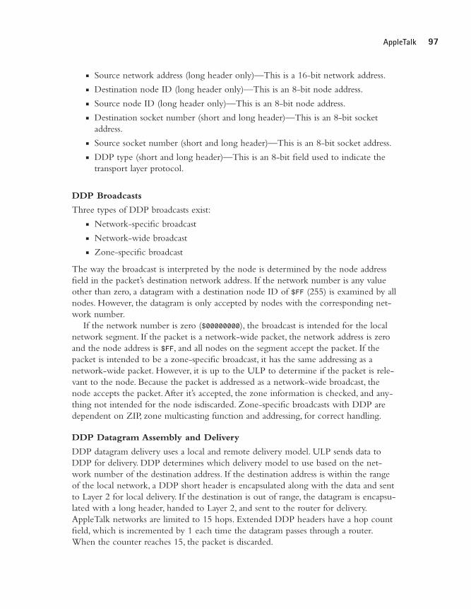
n Source network address (long header only)—This is a 16-bit network address.n Destination node ID (long header only)—This is an 8-bit node address.n Source node ID (long header only)—This is an 8-bit node address.n Destination socket number (short and long header)—This is an 8-bit socket
address.n Source socket number (short and long header)—This is an 8-bit socket address.n DDP type (short and long header)—This is an 8-bit field used to indicate the
transport layer protocol.
DDP Broadcasts
Three types of DDP broadcasts exist:n Network-specific broadcastn Network-wide broadcastn Zone-specific broadcast
The way the broadcast is interpreted by the node is determined by the node addressfield in the packet’s destination network address. If the network number is any valueother than zero, a datagram with a destination node ID of $FF (255) is examined by allnodes. However, the datagram is only accepted by nodes with the corresponding net-work number.
If the network number is zero ($00000000), the broadcast is intended for the localnetwork segment. If the packet is a network-wide packet, the network address is zeroand the node address is $FF, and all nodes on the segment accept the packet. If thepacket is intended to be a zone-specific broadcast, it has the same addressing as a network-wide packet. However, it is up to the ULP to determine if the packet is rele-vant to the node. Because the packet is addressed as a network-wide broadcast, thenode accepts the packet.After it’s accepted, the zone information is checked, and any-thing not intended for the node isdiscarded. Zone-specific broadcasts with DDP aredependent on ZIP, zone multicasting function and addressing, for correct handling.
DDP Datagram Assembly and Delivery
DDP datagram delivery uses a local and remote delivery model. ULP sends data toDDP for delivery. DDP determines which delivery model to use based on the net-work number of the destination address. If the destination address is within the rangeof the local network, a DDP short header is encapsulated along with the data and sentto Layer 2 for local delivery. If the destination is out of range, the datagram is encapsu-lated with a long header, handed to Layer 2, and sent to the router for delivery.AppleTalk networks are limited to 15 hops. Extended DDP headers have a hop countfield, which is incremented by 1 each time the datagram passes through a router.When the counter reaches 15, the packet is discarded.
03 9777 CH03 5/21/01 3:42 PM Page 97

98 Chapter 3 The Networker’s Guide to AppleTalk, IPX, and NetBIOS
AppleTalk Layer 4 (Transport) ProtocolsAppleTalk’s Layer 4 protocols all contribute to providing the following end-to-endtransport services for ULP data between end-nodes:
n Routing table creation and maintenancen AppleTalk internetwork transport services over TCP/IPn End-node ratabilityn Binary network addressing (physical addressing) to network-named entity
(contextual addressing) translation servicesn Connection-oriented socket data transport
Routing Table Maintenance Protocol
AppleTalk routing is a dynamic process.Although network addresses are statically set,node addresses are usually assigned dynamically, so static addressing has a very limitedvalue. End-nodes can determine if a datagram is to be delivered locally or remotely. Ifthe destination is remote, the router takes over.The router’s main job is to maintaininformation about different network segments that are reachable within the internet-work.This information includes the following:
n Network (cable) rangen Distance to network in hopsn Router interface used to reach the destination networkn Network address of the next hop node
There are three types of routers used in AppleTalk internetworks:n Local routers are used to connect locally adjacent AppleTalk network segments.A
local router is used to segment a large physical network into different networksegments.
n Half routers are used for point-to-point WAN connections. One half is connectedto a local AppleTalk segment, and the other half is connected to the WAN link.The nature of transport used by the link can be a modem, a public data net-work, and so on.
n Backbone routers are used to transport AppleTalk traffic across another non-AppleTalk network.The backbone transit network encapsulates AppleTalk datain its transport format.
In the case of local and half routers,AppleTalk protocols are used throughout theinterconnect path. Backbone routers use AppleTalk in conjunction with another pro-tocol (usually TCP/IP) to provide data transport. Regardless of router type, onlyAppleTalk reliability information is contained in routing tables.
03 9777 CH03 5/21/01 3:42 PM Page 98
99AppleTalk
AppleTalk routing table creation all starts with a single router known as the seedrouter. The job of the seed router is to provide non-seed routers with network addressinformation.The seed router has the network range statically set on its ports.A non-seed router does not. For a one-router or multiple router network, one seed router isneeded.
When an AppleTalk router starts up, it creates a table of all the connected networksegments.This is known as a routing seed (not to be confused with a seed router). Eachdefined network (with a nonzero network number) is entered as a local network witha hop distance of zero.A seed router builds a table network range associated with eachrouter interface.A non-seed router builds a table with all the interfaces using a net-work address of zero.After the routing table is created, the router sends out a routingupdate containing all the networks it can reach out of each of its connected interfaces.The seed router sends updates to routers with all of the correct network address infor-mation.The non-seed routers then use this network address information to updatetheir tables.
Routing Table Maintenance Protocol (RTMP) is similar to the Routing InformationProtocol (RIP) covered in Chapter 8,“TCP/IP Dynamic Routing Protocols,” exceptone value is used to determine which route is the best route.This value is called arouting metric. AppleTalk uses a routing metric known as the hop count. Hop count isdetermined based on the number of routers that must be traversed in order to reachthe destination network. If a network is directly connected to a network, the hopcount to reach the network is zero.An RTMP uses a technique called split horizon toprevent routing loops (discussed in Chapter 8).
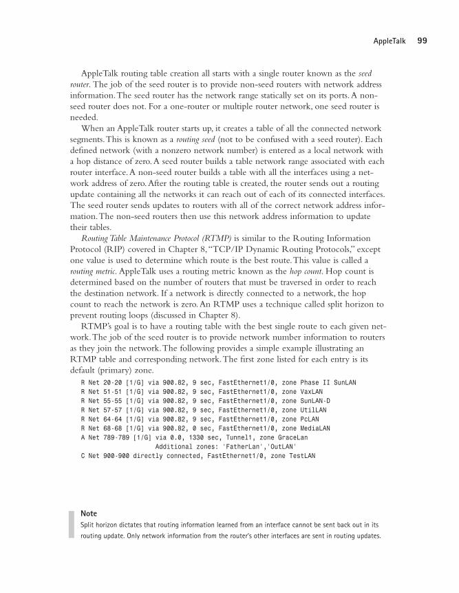
RTMP’s goal is to have a routing table with the best single route to each given net-work.The job of the seed router is to provide network number information to routersas they join the network.The following provides a simple example illustrating anRTMP table and corresponding network.The first zone listed for each entry is itsdefault (primary) zone.
R Net 20-20 [1/G] via 900.82, 9 sec, FastEthernet1/0, zone Phase II SunLANR Net 51-51 [1/G] via 900.82, 9 sec, FastEthernet1/0, zone VaxLANR Net 55-55 [1/G] via 900.82, 9 sec, FastEthernet1/0, zone SunLAN-DR Net 57-57 [1/G] via 900.82, 9 sec, FastEthernet1/0, zone UtilLANR Net 64-64 [1/G] via 900.82, 9 sec, FastEthernet1/0, zone PcLANR Net 68-68 [1/G] via 900.82, 0 sec, FastEthernet1/0, zone MediaLANA Net 789-789 [1/G] via 0.0, 1330 sec, Tunnel1, zone GraceLan
Additional zones: ‘FatherLan’,’OutLAN’C Net 900-900 directly connected, FastEthernet1/0, zone TestLAN
NoteSplit horizon dictates that routing information learned from an interface cannot be sent back out in its
routing update. Only network information from the router’s other interfaces are sent in routing updates.
03 9777 CH03 5/21/01 3:42 PM Page 99
100 Chapter 3 The Networker’s Guide to AppleTalk, IPX, and NetBIOS
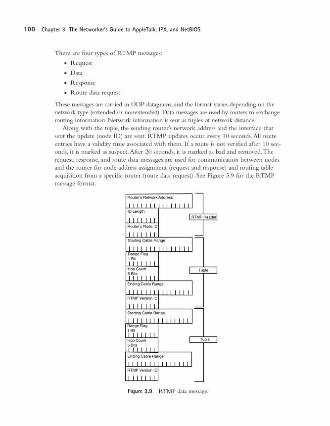
There are four types of RTMP messages:n Requestn Datan Responsen Route data request
These messages are carried in DDP datagrams, and the format varies depending on thenetwork type (extended or nonextended). Data messages are used by routers to exchangerouting information. Network information is sent as tuples of network distance.
Along with the tuple, the sending router’s network address and the interface thatsent the update (node ID) are sent. RTMP updates occur every 10 seconds.All routeentries have a validity time associated with them. If a route is not verified after 10 sec-onds, it is marked as suspect.After 20 seconds, it is marked as bad and removed.Therequest, response, and route data messages are used for communication between nodesand the router for node address assignment (request and response) and routing tableacquisition from a specific router (route data request). See Figure 3.9 for the RTMPmessage format.
ID Length
Router’s Node ID
Hop Count5 Bits
Starting Cable Range
Ending Cable Range
Router’s Network Address
Range Flag1 Bit
RTMP Version ID
Hop Count5 Bits
Starting Cable Range
Ending Cable Range
Range Flag1 Bit
RTMP Version ID
RTMP Header
Tuple
Tuple
Figure 3.9 RTMP data message.
03 9777 CH03 5/21/01 3:42 PM Page 100

101AppleTalk
AppleTalk Update Based Routing Protocol
AppleTalk Update Based Routing Protocol (AURP) is not a routing protocol. Rather, itprovides a means for connecting AppleTalk internetworks across TCP/IP networks.The AURP transport mechanism operates as a tunnel through which all AppleTalkprotocol data is encapsulated using TCP/IP User Datagram Protocol (UDP) packets asthe transport and IP for delivery.AURP implementations have two parts: exterior routersand the AURP tunnel.
Exterior routers (backbone routers) are the bridge routers between the AppleTalkinternetwork and the AURP tunnel.The AURP tunnel is the logical conduit built ontop of the local and remote IP interfaces of the exterior routers involved with theAURP exchange.Two types of AURP tunnels exist:
n A single point-to-point tunnel is where all AppleTalk data is exchanged betweenthe two internetworks.
n A multipoint tunnel is where three or more AppleTalk internetworks are con-nected. Multipoint tunnels can be fully connected or partially connected whereonly some internetworks are available.
AURP routing updates are adjustable and triggerable when changes in one of theconnecting internetworks occur. Initially, routing and zone information tables areexchanged across the tunnel between the connected internetworks when the AURPtunnel is initialized. Updates use TCP or AURP-Tr which both provide reliable transport.This makes AURP a more efficient alternative for connecting AppleTalkinternetworks as compared to traditional AppleTalk point-to-point connections.
AURP also introduces the concept of AppleTalk domains.A domain identifier is associated with each internetwork connected to the tunnel. Domain identifiers can be statically or dynamically set.
64-bit domain-id/ 16-bit network address/ 8-bit node address/ 8-bit socket address
AURP also provides facilities for hiding networks, internetwork address conflicts, routepath redundancy, and hop count reduction.AURP configuration will be covered inChapter 10.
AppleTalk Echo Protocol
AppleTalk Echo Protocol (AEP) is used for packet generation to test node reachabilityand network performance.AEP uses static socket 4 as the echoer socket (receiver) anda dynamically assigned socket as the sender.AEP supports two functions: request and reply.
NoteRemember, AppleTalk internetworks have a distance limitation of 15 hops.
Packets with a distance of 16 are discarded.
03 9777 CH03 5/21/01 3:42 PM Page 101
102 Chapter 3 The Networker’s Guide to AppleTalk, IPX, and NetBIOS
Name Binding Protocol
Name Binding Protocol (NBP) is the basis of AppleTalk’s contextual addressing scheme.Its purpose is to identify each network service available on a given end-node with asymbolic name.After a service has an entity name associated with it, it becomes anNVE. Name registration is a process similar to dynamic address assignment.The net-work service registers its name with the end-host.The end-host then checks its nametable to ensure that there is no conflict. If no conflict is found on the local name table,the service name is broadcast to all the nodes on the zone/cable range. If no conflict isfound, the name is used. If a conflict arises during the local and network verificationstage, the registration process is halted.After the NVE is available, its entity name hasthree parts:
object:type@zone
n object is the service’s symbolic name (Montana, Moe’s printer, and so on).This can be any name up to 32 characters in length.
n type is the service classification.This could be a mail server, printer, file server,and so on.
n @zone is the logical contextual network group where the printer resides.
This approach works well from a user interface perspective. Because AppleTalk usesdynamic addressing, statically named entities are easy for users to relate to as comparedto a changing 32-bit network/node/socket address.
NBP name table creation occurs on each node on the network. NBP tables are ini-tially created when the node joins the network and are updated as interaction withentities occurs.The NBP name table entries are sent and stored as tuples, which con-tain translations of network, node, and socket numbers to object, type, and zone foreach available service. Lookups and updates are performed using local broadcasts (localname enquiries) and zone broadcasts (for remote name enquiries that are redirected byAppleTalk routers). Every host within the directed segment responds to a lookuprequest, checking its local name table and sending the result to the requester.
There are four services used for name table maintenance and lookups:n Name registration is the process of services registering their entity names with the
local end-node and network (cable range/zone) segment.n Name deletion occurs when an NVE is removed from the network.n Name lookup is performed whenever a node wishes to access an NVE. Requests
are queried as either specific or global searches.The type of query dictates therequest type (local broadcast or zone specific broadcast/multicast).
n Name confirmation is used to verify aged name table entries. Confirmations areperformed prior to session establishment with an NVE.The process is different(and more efficient) than a name lookup, as the inquiry is sent directly to theNVE’s hosting end-node.
03 9777 CH03 5/21/01 3:42 PM Page 102
103AppleTalk
NBP is the end-node-oriented protocol used for providing AppleTalk’s contextualnetwork naming scheme. ZIP is the session layer element used for contextual networksegmentation.These two protocols are used in conjunction with RTMP to establishnetwork data flow and user interaction. Each element can be used to modify networkbehavior and performance. ZIP is covered in the Layer 5 session protocols section.
AppleTalk Transaction Protocol
AppleTalk Transaction Protocol (ATP) provides acknowledged transmission servicebetween sockets. Each network transaction consists of two actions: request andresponse. In most cases, the transmission is a client end-station interacting with a fileserver or printer. Each ATP request and response must be acknowledged with a trans-action request and transaction response to report the outcome of the action.Thisapproach is used by ATP to provide data acknowledgment, packet sequencing, datasegmentation, and reassembly, which is needed to handle data loss due to networktransmission errors.There are three types of ATP transactions: request, response, andrelease.The release transaction is used to end an ATP session.
ATP uses two types of transaction services to handle error correction:n At-Least-Once (ALO)n Exactly-Once (EO)
ALO transaction services are used by applications that return the same outcome if the transaction is executed more than once. For example, if a host performs a namelookup, the response is the same regardless of which transaction is successful. EO transaction services are used if duplicate requests would affect the success of the transaction.With EO, a transactions list is maintained, so duplicate transactions are performed only once if a data loss condition exists. All ATP transmissions are timed,and the duration varies depending on the type of ATP transaction.
AppleTalk Layer 5 (Session), Layer 6 (Presentation), and Layer 7(Application) ProtocolsSix protocols make up AppleTalk’s upper layer protocol suite: four session layer proto-cols (Layer 5) and two presentation layer protocols (Layer 6).The session layer protocols are used for session negotiation and communication between the lower layer network protocols and end-node application data, which is provided by the presentation and application layers.AppleTalk has no protocol defined application protocol suite; rather, it uses the AppleTalk Filing Protocol (AFP) and PostScript toprovide presentation services and application interface hooks.
03 9777 CH03 5/21/01 3:42 PM Page 103

104 Chapter 3 The Networker’s Guide to AppleTalk, IPX, and NetBIOS
Zone Information Protocol
Zone Information Protocol (ZIP) is used to create and maintain Zone Information Tables(ZITs) on AppleTalk routers.AppleTalk Phase 1 network supports a direct networkaddress-to-zone association. Phase 2 networks can support up to 255 zone names perextended cable range. Zones are used for creating logical contextual network groups toprovide user level network segmentation.The idea is that you can group clients,servers, and printers within the same logical group, making user resources more easilyaccessible.
Like RTMP and NBP, ZIT entries are stored as tuples: network number and zonename.AppleTalk Phase 1 network tuples are a single network number to a single zone name.AppleTalk Phase 2 network tuples are cable range(s) (extended and nonextended) to zone names.The RTMP and ZIP are used in conjunction on theAppleTalk router to direct NBP packets to the correct router interface.
Client/server interaction with ZIP is limited in use to selecting a zone.The clientzone name setting is stored in the system’s boot PRAM ZIP; when it boots, it verifiesthe zone name (and its corresponding network address). If no setting is available, therouter provides the default zone to the client. ZIP uses five different message requestsfor table maintenance and zone verification.
n ZIP query messages are used to request a router’s zone list.n ZIP response messages are used to return the zone list.n ZIP extended reply messages are used to fragment the list into multiple packets if
the ZIT cannot fit into a single packet.n ZIP GetNetInfo is used by clients to verify its zone name at boot time.n ZIP GetNetInfoReply is used to respond to client zone verification requests and
provide the zone’s multicast address.
An illustration of a zone table appears in Table 3.1.Table 3.1 A Sample Zone Table
Zone Name Cable Range
MediaLAN 68-68Phase II SunLAN 20-20SunLAN-D 55-55VaxLAN 51-51OutLAN 789-789InLANHappyLANPcLAN 64-64UtilLAN 57-57FatherLan 789-789TestLAN 900-900HOMElanGraceLan 789-789
Each message type has its own message format and is sent using DDP datagrams, illus-trated in Figure 3.10.
03 9777 CH03 5/21/01 3:42 PM Page 104

105AppleTalk
Each zone also has an associated binary multicast address.The multicast address pro-vides a way to send broadcast messages between nodes belonging to the zone.Theaddress is generated by processing the zone name through the DDP checksum algo-rithm and dividing the result by 255.The address is provided to the host as part of itsinitial zone registration/verification process.
AppleTalk Data-Stream Protocol
AppleTalk Data-Stream Protocol (ADSP) is used to provide reliable full-duplex datatransmission for client/server socket data delivery.ADSP is directly encapsulated intoDDP datagrams, and provides facilities for flow control and packet sequencing.
ADSP data exchange requires a socket-to-socket connection stream to be estab-lished before data can be exchanged. If either node drops or is unable to establish thestream connection, the session is dropped.To establish communication sessions,ADSPuses control packets, which are used for connection-related processes such as opening orclosing connections, retransmission requests, or connection acknowledgment. Data issent in ADSP data packets. Out of data flow messaging is also available and is accom-plished with ADSP message packets. Each packet uses a specific ADSP header, and all aretransported inside of DDP datagrams.
Zip Query Message
Network AddressBeing Queried
Network Number
GetNetInfo Request Message
Network Number
Network Count
Zip Function(Query)
Zip Function(GetNetInfo Request)
Zone Name
Length of Zone Name
40-Bit Buffer
Zip Reply Message
Zip Function(Query)
Network Count
Network Number
Length ofZone Name
Zone Name
Zone and Network pairs:Multiple zone names canbe related to a single networknumber.
GetNetInfo Reply Message
Zip Function(GetNetInfo Reply)
Flag Bits
Network Number Range Start
Network Number Range End
Length of Zone Name
Zone Name
7 = Invalid zone6 = Use Broadcast5 = Only One Zone
Figure 3.10 ZIP message formats.
03 9777 CH03 5/21/01 3:42 PM Page 105

106 Chapter 3 The Networker’s Guide to AppleTalk, IPX, and NetBIOS
To ensure proper packet data sequencing,ADSP uses a 32-bit sequence number alongwith a packet identifier for each packet. If the sequence number and packet identifierdo not coincide, the packet is dropped. Flow control is achieved by the destinationsending periodic updates to the sender on the amount of available buffer space. Thisvalue is known as the reception window size.
AppleTalk Session Protocol
AppleTalk Session Protocol (ASP) provides a connection-oriented facility to exchangemultiplexed client/server session communications.ASP is used between clients andservers to exchange session commands. Clients’ commands are delivered in sequentialorder to servers who use ASP to return command results.ASP, however, provides nomeans to ensure that the server executes them consecutively.ASP operates as a multi-plexed process, providing servers with the means to maintain multiple client sessions atthe same time.The server has no means for sending commands to the client. Only anattention mechanism is available to the server to notify the client if any action isrequired on its behalf.ASP uses ATP for transport and NBP for service socket identifi-cation.
Printer Access Protocol
Printer Access Protocol (PAP) is used for client/server to printer communication. Itperforms connection setup and tear down, as well as data transfer.ATP is used as thetransport protocol and NBP (like ASP) is used for service (socket) addressing.
PAP transactions are time-based, as ATP is used as the transport mechanism. PAPwill maintain half-open connections for the duration of the timeout.After a connec-tion expires, the session is terminated.
Because AppleTalk printing is a device direct activity, PAP provides for a keepalivefacility. Tickle packets are sent periodically from the clients with open sessions to main-tain the connection and ensure that the printer is online and processing requests.
Presentation Layer Protocols
AppleTalk uses two protocols,AppleTalk Filing Protocol (AFP) and PostScript, fortranslating data responses (lower layer protocol) and requests (application layer) into acommon data encoding language.AFP is used for client remote file access. AFP is acommand translator that takes native file system calls and translates them into AFP callsthat the server understands. PostScript is a stack-based page-description language usedby printers and applications to mathematically describe objects.Apple QuickDraw isthe native page-description language used to display Macintosh characters and graphicsand is also used for printing to low resolution printers. QuickDraw acts as an operat-ing system level translator for data images to PostScript. PostScript is used to commu-nicate with the printer hardware to render the image for printing. Most commonprinting errors are related to corrupted QuickDraw-to-PostScript translations.
03 9777 CH03 5/21/01 3:42 PM Page 106
107IPX and NetBIOS
IPX and NetBIOSOnce upon a time, there was no such thing as Windows NT (and the world was anice place for UNIX system administrators). Novell NetWare and InternetworkingExchange Protocol (IPX) ran on 60 to 70 percent of all networked Intel/DOS-basedcomputers. Novell is a proprietary 100 percent DOS-compatible network operatingsystem (NOS). Its basic design goal was to provide shared file system and printer access transparently to desktop PCs through the I/O interfaces provided by DOS.Networked file systems were available to users as drive letters (such as E:\), and net-worked printers were available through virtual (LPR) printer ports. Novell NOS runson almost any Layer 2 protocol and is available for almost every major computer plat-form, keeping in mind, however, its first love (and primary orientation) is to DOS.Novell uses its own proprietary and closed architecture, based on Xerox’s open stan-dard, Xerox Network Systems (XNS).
The IPX is the original Novell NOS network layer protocol used for all networklayer communication.The Novell NOS versions 4.0 and later also operate overTCP/IP.
Novell also supports both proprietary and standards-based session protocols, whichunder the Novell model acts as the bridge between user applications and networktransport. Novell’s session protocols are as follows:
n NetWare Core Protocol (NCP) (Novell-specific)n NetWare Shell (NWS) (Novell-specific)n NetWare Remote Procedure Call (NRPC) (Novell-specific)n NetBIOS (open standard)
Novell’s support of NetBIOS was driven by a need for NetWare systems to interoper-ate with NetBIOS-based NOS, like IBM’s LAN Manager, which was the foundationof Microsoft’s Windows for Workgroups (Windows.9x) and Windows NT networkingenvironments. Microsoft’s implementation of IPX is called NWLink. NWLink is theMicrosoft version of the IPX protocol suite, and it is fully compatible and opera-tionally identical to Novell’s IPX/SPX protocols. It provides Windows-based systemsnative protocol access to both Novell NetWare and Microsoft networking services.
The IPX/NWLink protocols are implemented on Intel-based PCs, using eithernetwork device interface specification (NDIS) or open data-link interface (ODI)network driver interfaces. NDIS is a standard for interfacing between media accesscontrol (MAC) sublayer and network protocols. NDIS acts as a protocol multiplexer ortraffic director between Layer 3 (network protocol) and Layer 1 (hardware networkadapter), so multiple network protocols, such as TCP/IP and IPX, can be used on thesame computer. ODI is the Novell proprietary specification for providing the samefacility.
03 9777 CH03 5/21/01 3:42 PM Page 107

108 Chapter 3 The Networker’s Guide to AppleTalk, IPX, and NetBIOS
NetWare (IPX) Architecture: OSI Layer 1 and Layer 2The NetWare architecture model uses a five-layer model in contrast to OSI’s sevencommunication layers, as shown in Figure 3.11.
n Layer 0, the transmission media layer, is responsible for data exchange betweenthe end-node and the transmission media.
n Layer 1, the Internet layer, provides a data exchange facility between end-nodesconnected on different networks.
n Layer 2, the transport layer, handles end-to-end communication between end-nodes.
n Layer 3, the control layer, provides session control and data presentation services.n Layer 4, the application layer, manages data semantics between client and server
interactions such as login, file, and print services.
Presentation
Session
Data Link
Transport
Application
Network
Net
BIO
S NetWareCoreProtocol(NCP)
NetWareApplications
NetWareShell
Physical
RPCApplications
RPC
SPXRIP
IPX
SAP
Ethernet, FDDI, Token Ring
Figure 3.11 Novell (IPX) protocol suite.
Where TCP/IP and AppleTalk are unaware of Layer 2 (OSI-RM), IPX operates inconjunction with it.The most obvious example of this symbiosis is the IPX’s end-node number.The IPX end-node number is the NIC’s unique hardware address.Theother, slightly more complex dualism is IPX’s use of hardware encapsulation.
IPX operates over several LAN and WAN transmission media formats, includingEthernet,Token Ring, FDDI, and Point-to-Point Protocol (PPP). NetWare, in itsoriginal form, supported a single proprietary encapsulation format. However, as Layer2 technologies evolved (just as with AppleTalk), IPX was adjusted to operate with thenew encapsulation formats, of which IPX supports several (see Table 3.2).
03 9777 CH03 5/21/01 3:42 PM Page 108
109IPX and NetBIOS
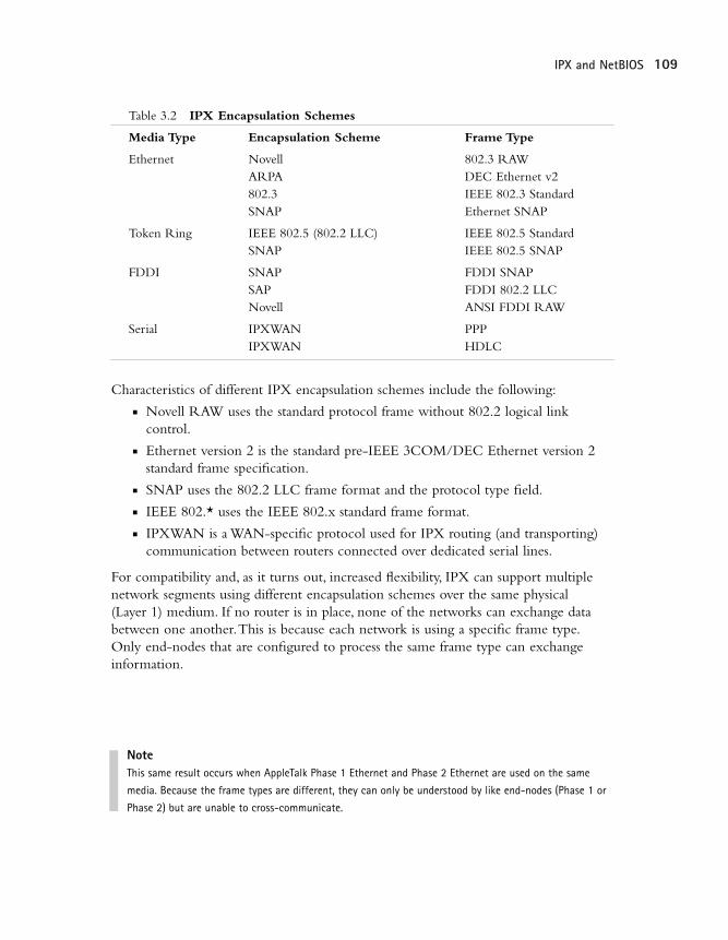
Table 3.2 IPX Encapsulation Schemes
Media Type Encapsulation Scheme Frame Type
Ethernet Novell 802.3 RAWARPA DEC Ethernet v2802.3 IEEE 802.3 StandardSNAP Ethernet SNAP
Token Ring IEEE 802.5 (802.2 LLC) IEEE 802.5 StandardSNAP IEEE 802.5 SNAP
FDDI SNAP FDDI SNAPSAP FDDI 802.2 LLCNovell ANSI FDDI RAW
Serial IPXWAN PPPIPXWAN HDLC
Characteristics of different IPX encapsulation schemes include the following:n Novell RAW uses the standard protocol frame without 802.2 logical link
control.n Ethernet version 2 is the standard pre-IEEE 3COM/DEC Ethernet version 2
standard frame specification.n SNAP uses the 802.2 LLC frame format and the protocol type field.n IEEE 802.* uses the IEEE 802.x standard frame format.n IPXWAN is a WAN-specific protocol used for IPX routing (and transporting)
communication between routers connected over dedicated serial lines.
For compatibility and, as it turns out, increased flexibility, IPX can support multiplenetwork segments using different encapsulation schemes over the same physical (Layer 1) medium. If no router is in place, none of the networks can exchange databetween one another.This is because each network is using a specific frame type.Only end-nodes that are configured to process the same frame type can exchangeinformation.
NoteThis same result occurs when AppleTalk Phase 1 Ethernet and Phase 2 Ethernet are used on the same
media. Because the frame types are different, they can only be understood by like end-nodes (Phase 1 or
Phase 2) but are unable to cross-communicate.
03 9777 CH03 5/21/01 3:42 PM Page 109

110 Chapter 3 The Networker’s Guide to AppleTalk, IPX, and NetBIOS
The other nodes on the network that are configured to use other frame types discard theframes, believing them to be malformed.The encapsulation type must be set correctly onall routers, servers, and clients that need to interact locally. Incorrect encapsulation is acommon IPX network problem, so when in doubt, check the settings.
NetWare (IPX) Architecture: OSI Layer 3IPX, like TCP/IP’s Internet Protocol (IP) and AppleTalk’s Datagram Delivery Protocol(DDP), is the sole network layer delivery protocol for NetWare (and NWLink-basedLAN manager implementations). IPX is a routable, connectionless datagram deliveryprotocol. Its original implementation operated around the Routing InformationProtocol (RIP) as a routing protocol that is part of the IPX process and operates auto-matically whenever IPX is used (similar to AppleTalk’s RMTP).Today, IPX can utilizeNetWare Link State Protocol (NLSP) and Cisco’s Enhanced Interior GatewayRouting Protocol (EIGRP) routing protocols to exchange route information.
IPX (NWLink) Addressing
IPX datagram delivery provides facilities for local network and (remote) internetworkdata exchanges. IPX datagram delivery points are known as ports. IPX ports are justlike AppleTalk sockets.While a ULP is responsible for the actual data transport, thesource/destination port is part of the IPX packet address. Figure 3.12 illustrates theIPX network address format.
48-Bit Node Address
16-Bit Port Address
32-Bit Network Address
Figure 3.12 IPX address format.
The IPX address has three components:n Networkn Noden Port
The network address is 32 bits in length, generally expressed as a single string of hexa-decimal digits.The node address is 48 bits in length, expressed as three dotted tripletsof a pair of hexidecimal numbers or six dotted pairs of hexidecimal numbers.Theport address is 16 bits in length expressed as a single four-digit hexidecimal number.
03 9777 CH03 5/21/01 3:42 PM Page 110

111IPX and NetBIOS
The IPX address is therefore a total of 96 bits in size, which is large for a networkaddress. Datagram sizes vary depending on the encapsulation type and network mediatype being used for transport.
The IPX network address needs to be set by the network administrator. LikeAppleTalk, the network address can be a random number, but each must be unique.
IPX uses the end-station’s NIC hardware or MAC address for the node address.This makes IPX stations, in a sense, self-configuring.This approach also eliminates theneed for a Layer 2 to Layer 3 address resolution protocol.This, in turn, reduces packetdelivery complexity and network traffic. However, there is an associated disadvantageof having to replicate the Layer 2 address twice in the data frame.This reduces theamount of actual data that can be transported in each frame.
IPX’s port communication exchange process is quite simple. Known services useknown port numbers, and dynamic data exchanges (file transfers, for example) usedynamic port numbers (see Table 3.3).
Table 3.3 Port Address Assignments for IPX
Port Service Assignment Number
Wild Card (all sockets) 0
NetWare Core Protocol 451
Service Advertisement Protocol 452
IPX RIP 453
NetBIOS 455
Novell Diagnostic Packet 456
Novell Serialization Packet 457
Dynamic Sockets 4000-6000
IPX Message Format
The IPX datagram header is, basically, all the addressing information needed for IPX’ssimple original orientation toward LAN-based datagram exchange. Figure 3.13describes the message format.
n Checksum is a 16-bit field. Checksumming is not enabled by default in IPX, sothe field is often unused and set to a default (FFFF). IPX relies on Layer 2 forerror checking.
n Packet length is a 16-bit descriptor expressing the size of the entire IPX packet.n Transport control is an 8-bit value that describes the number of hopsan IP
packet has traversed. It is decremented by 1 each time it passes through a router.When 16 is reached, this is the maximum hop count for an IPX network, andthe packet is dropped.
03 9777 CH03 5/21/01 3:42 PM Page 111

112 Chapter 3 The Networker’s Guide to AppleTalk, IPX, and NetBIOS
n Packet type is used to indicate the kind of data contained in the datagram.0 = Unknown, 1 = RIP, 4 = SAP, 5 = SPX, 17 = NCP, 20 = NetBIOS.
n Destination network is a 32-bit field. If the sender is local, this value is 0.n Destination node is a 48-bit field. Unicast messages use the MAC/IPX address
of the destination end-node. Broadcast messages use all zeros.n Destination port is a 16-bit field that indicates the ULP service port destination
address.n Source network is a 32-bit field.A 0 here indicates that the datagram is either
unknown or a network broadcast.n Source node is a 48-bit field, indicating the sender’s address.n Source port a 16-bit field that describes the sender’s originating port (should be
the same as the destination port number).
Packet Length
TransportControl
Checksum
Destination Network
Destination Node
Packet Type
Source Node
Source Port
Source Network
Destination Port
Figure 3.13 IPX datagram format.
The data field will contain the ULP header and data. IPX is used to transport all net-work messages, including SAP and IPX messages, which are technically part of IPX.
03 9777 CH03 5/21/01 3:42 PM Page 112

113IPX and NetBIOS
IPX Datagram Delivery
Like IP and AppleTalk, IPX uses a local and remote delivery model. IPX is used fordatagram delivery, SAP is used to announce the services on the network, and RIP isused to determine how to reach these services. Both SAP and RIP will be examinedin detail in the following sections.
When a server or router joins the network, it constructs a table listing all the ser-vices it provides (server) or all the servers and services it knows about (router). Bothrouters and servers announce this information periodically to the network.When aclient joins the network, it needs to find out what its network address is and whichserver to attach to. It accomplishes these functions by listening for an IPX RIP mes-sage or by sending a GetLocalTarget broadcast request.A GiveLocalTarget response issent to the client in response to the broadcast message.The client, in turn, learns itsnetwork address from the source network address of the update or response packet.The client then sends a GetNearestServer broadcast to learn the address of the nearestserver.This is responded to by all available servers (and routers) with aGiveNearestServer message.These responses are stored locally in the client’s SAP tableand used to determine the best server to connect to.
IPX datagram delivery is determined by first determining the destination’s networkaddress.The end-station’s address is compared to the server’s address (in the SAP table),and if they are local to one another a connection is established. If the client and serverare not local, a RIP request is made for the shortest and fastest path.The client thendetermines which path is the best path based on the information provided by therouter(s).This is important to note because the client determines the network paththat will be taken instead of just forwarding the datagram on to a router that makesthat determination.
Service Advertising Protocol
Service Advertising Protocol (SAP) is an IPX support protocol through which service-providing end-nodes (servers) advertise their specific services (see Figure 3.14). SAPinformation needs to be available across the entire internetwork in order for IPX hostswho have knowledge of their available services to share this with other hosts. Routerscollect local SAP updates and broadcast a single SAP update based on the cumulativeinformation gleaned from other router updates.This allows clients to become aware ofservers that are local. Updates contain the server name, network address, and SAP ser-vice identifier (indicating the type of service available).
03 9777 CH03 5/21/01 3:42 PM Page 113

114 Chapter 3 The Networker’s Guide to AppleTalk, IPX, and NetBIOS
Figure 3.14 SAP message flows between servers and routers.
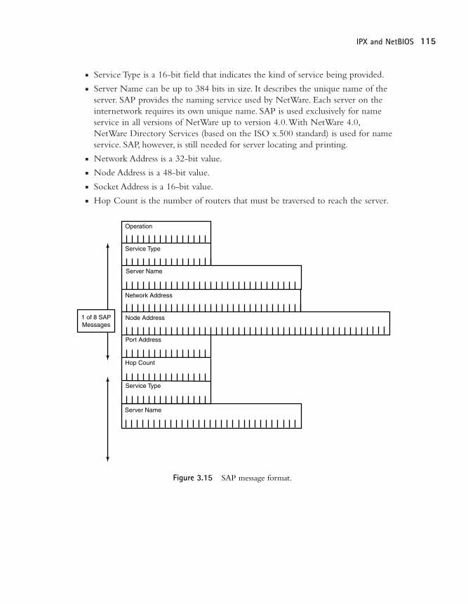
SAP is used by both clients and servers for requesting and responding to informationabout available network resources. SAP messages support four distinct operation typesand contain information about eight nodes per message (see Figure 3.15).
n Operation is a 16-bit field that describes the packet’s informational purpose.
• Request is a general informational request about all the servers on the network.
• Response is a reply to a SAP request or a general SAP announcement sent byservers and routers every 60 seconds (default).
n GetNearestServer is a specific request sent by a host to locate the nearest server.n GiveNearestServer is a response sent by a router or server with the SAP infor-
mation about the server closest to the requesting end-station.
Sad
Net 00003455
Routers SAPPluto
Mickey
The routers SAP informs thelocal nodes of the remote servers.
Pluto
Net 00044556
The local server's SAPs informthe local nodes.
Happy
Mickey
Routers SAPSad
Happy
03 9777 CH03 5/21/01 3:42 PM Page 114
115IPX and NetBIOS
n Service Type is a 16-bit field that indicates the kind of service being provided.n Server Name can be up to 384 bits in size. It describes the unique name of the
server. SAP provides the naming service used by NetWare. Each server on theinternetwork requires its own unique name. SAP is used exclusively for nameservice in all versions of NetWare up to version 4.0.With NetWare 4.0,NetWare Directory Services (based on the ISO x.500 standard) is used for nameservice. SAP, however, is still needed for server locating and printing.
n Network Address is a 32-bit value.n Node Address is a 48-bit value.n Socket Address is a 16-bit value.n Hop Count is the number of routers that must be traversed to reach the server.
Operation
Service Type
Server Name
Network Address
1 of 8 SAPMessages
Node Address
Port Address
Hop Count
Service Type
Server Name
Figure 3.15 SAP message format.
03 9777 CH03 5/21/01 3:42 PM Page 115
116 Chapter 3 The Networker’s Guide to AppleTalk, IPX, and NetBIOS
Updates are sent out every 60 seconds. In large IPX environments, SAPs can consumea noticeable amount of bandwidth. One way to alleviate this is by having routersbroadcast “combined” SAP updates. It is also possible to adjust the intervals duringwhich routers send out SAP updates.This is especially useful over WAN links wherebandwidth is limited.To calculate the SAP bandwidth network load, add 32 (SAPmessage header) plus 64 (SAP entry) per SAP device.The total will tell you the totalbandwidth per minutes used by SAP.
IPX Routing Information Protocol
IPX RIP is a variation of TCP/IP RIP version 1.The RIP version 1 routing protocolis fully explained in Chapter 9. Only the IPX specifics are covered in this section. IPXRIP uses a “best path” route metric value to determine the best path to reach a net-work.The best path value is based on two factors:
n Hop count—Number of routers a packet must travel through to reach its destination
n Ticks—Used to represent network delay
Not all IPX RIP implementations support ticks, and in these cases only hop count isused.
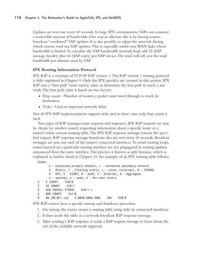
Two types of RIP messages exist: requests and responses. IPX RIP requests are sentby clients (or another router) requesting information about a specific route or arouter’s entire current routing table.The IPX RIP response message returns the speci-fied request. RIP response message broadcasts also are sent every 60 seconds. Broadcastmessages are sent out each of the router’s connected interfaces.To avoid routing loops,routes learned on a particular routing interface are not propagated in routing updatesannounced from the same interface.This practice is known as split horizon, which isexplained in further detail in Chapter 10.An example of an IPX routing table follows:
Codes: C - Connected primary network, c - Connected secondary networkS - Static, F - Floating static, L - Local (internal), W – IPXWANR - RIP, E - EIGRP, N - NLSP, X - External, A – Aggregates - seconds, u - uses, U - Per-user static
C 5 (SNAP) Et0/0C 45 (SNAP) Et0/1C 556 (NOVELL-ETHER) Et0/1.1C 899 (SNAP) Fa1/0R 88 [02/01] via 5.00e0.b06a.460e 36s Et0/0
IPX RIP routers have a specific startup and shutdown procedure:
1. On startup, the router creates a routing table using only its connected interfaces.
2. It then sends this table as a network broadcast RIP response message.
3. After sending a RIP response, it sends a RIP request message to learn about therest of the available network segments.
03 9777 CH03 5/21/01 3:42 PM Page 116
117IPX and NetBIOS
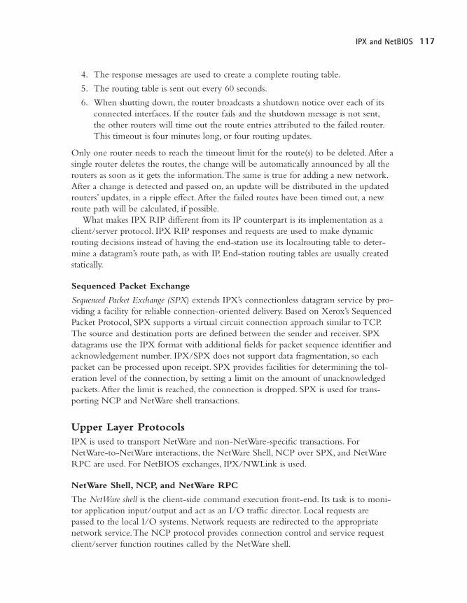
4. The response messages are used to create a complete routing table.
5. The routing table is sent out every 60 seconds.
6. When shutting down, the router broadcasts a shutdown notice over each of itsconnected interfaces. If the router fails and the shutdown message is not sent,the other routers will time out the route entries attributed to the failed router.This timeout is four minutes long, or four routing updates.
Only one router needs to reach the timeout limit for the route(s) to be deleted.After asingle router deletes the routes, the change will be automatically announced by all therouters as soon as it gets the information.The same is true for adding a new network.After a change is detected and passed on, an update will be distributed in the updatedrouters’ updates, in a ripple effect.After the failed routes have been timed out, a newroute path will be calculated, if possible.
What makes IPX RIP different from its IP counterpart is its implementation as aclient/server protocol. IPX RIP responses and requests are used to make dynamicrouting decisions instead of having the end-station use its localrouting table to deter-mine a datagram’s route path, as with IP. End-station routing tables are usually createdstatically.
Sequenced Packet Exchange
Sequenced Packet Exchange (SPX) extends IPX’s connectionless datagram service by pro-viding a facility for reliable connection-oriented delivery. Based on Xerox’s SequencedPacket Protocol, SPX supports a virtual circuit connection approach similar to TCP.The source and destination ports are defined between the sender and receiver. SPXdatagrams use the IPX format with additional fields for packet sequence identifier andacknowledgement number. IPX/SPX does not support data fragmentation, so eachpacket can be processed upon receipt. SPX provides facilities for determining the tol-eration level of the connection, by setting a limit on the amount of unacknowledgedpackets.After the limit is reached, the connection is dropped. SPX is used for trans-porting NCP and NetWare shell transactions.
Upper Layer ProtocolsIPX is used to transport NetWare and non-NetWare-specific transactions. ForNetWare-to-NetWare interactions, the NetWare Shell, NCP over SPX, and NetWareRPC are used. For NetBIOS exchanges, IPX/NWLink is used.
NetWare Shell, NCP, and NetWare RPC
The NetWare shell is the client-side command execution front-end. Its task is to moni-tor application input/output and act as an I/O traffic director. Local requests arepassed to the local I/O systems. Network requests are redirected to the appropriatenetwork service.The NCP protocol provides connection control and service requestclient/server function routines called by the NetWare shell.
03 9777 CH03 5/21/01 3:42 PM Page 117

118 Chapter 3 The Networker’s Guide to AppleTalk, IPX, and NetBIOS
NetWare RPC allows clients to remotely execute commands on the NetWareserver as an alternative to using the NetWare shell and NCP.
NCP is a proprietary Novell protocol that operates as a simpler version of TCP.NCP performs message sequencing instead of TCP’s byte-level sequencing. NCP mes-sages use a sequence number that is employed by the client and server to trackresponses. If the server sends a packet with the sequence number 8, the server willreply to the request with the sequence number 8. NCP data exchanges flow in onedirection: client (using NCP request packets) to server (using NCP response packets).The messages are handled one sequence number at a time.When the client sends arequest message, it waits for a reply message with the correct sequence number. If noreply is received, a timeout is reached and the transaction starts again using a sequencenumber increased by 1. If a server receives a packet with the same sequence number, itretransmits its response. If a client receives a message with a sequence number it hasalready received, the packet is dropped.
NCP function routines include the following:n Remote file system accessn System accountingn Name servicen Printing access
NetBIOSIn 1984, Sytec, an IBM subcontractor, created the Network Basic Input/Output System(NetBIOS). It was designed to provide OSI-RM Layer 4 full-duplex transmission ser-vice and OSI-RM Layer 5 session services. NetBIOS was originally published in theIBM PC Network Technical Reference Manual and has evolved as a de facto standard.Thestandard defines a collection of functions to be used with NetBIOS’s message controlblock (MCB) scheme.The MCB scheme takes a block of data, formats it as an MCB,and delivers it, utilizing the defined NetBIOS functions.
NoteRemember, NCP and the NetWare shell are used only to provide NetWare specific functions; they are not
used for processing NetBIOS interactions.
03 9777 CH03 5/21/01 3:42 PM Page 118
119IPX and NetBIOS
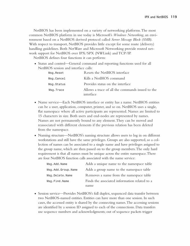
NetBIOS has been implemented on a variety of networking platforms.The mostcommon NetBIOS platform in use today is Microsoft’s Windows Networking, an envi-ronment based on a NetBIOS derived protocol called Server Message Block (SMB).With respect to transport, NetBIOS provides little except for some route (delivery)handling guidelines. Both NetWare and Microsoft Networking provide routed net-work support for NetBIOS over IPX/SPX (NWLink) and TCP/IP.
NetBIOS defines four functions it can perform:n Status and control—General command and reporting functions used for all
NetBIOS session and interface calls:Msg.Reset Resets the NetBIOS interface
Msg.Cancel Kills a NetBIOS command
Msg.Status Provides status on the interface
Msg.Trace Allows a trace of all the commands issued to theinterface
n Name service—Each NetBIOS interface or entity has a name. NetBIOS entitiescan be a user, application, computer, printer, and so on. NetBIOS uses a single,flat namespace where all active participants are represented. Names are limited to15 characters in size. Both users and end-nodes are represented by names.Names are not permanently bound to any element.They can be moved andreassociated with different elements if the previous relation has been deletedfrom the namespace.
n Naming structure—NetBIOS’s naming structure allows users to log in on differentworkstations and still have the same privileges. Groups are also supported, so a col-lection of names can be associated to a single name and have privileges assigned tothe group name, which are then passed on to the group members.The only hardrequirement is that all names must be unique across the entire namespace.Thereare four NetBIOS function calls associated with the name service:
Msg.Add.Name Adds a unique name to the namespace table
Msg.Add.Group.Name Adds a group name to the namespace table
Msg.Delete.Name Removes a name from the namespace table
Msg.Find.Name Finds the associated information related to aname
n Session service—Provides NetBIOS’s full duplex, sequenced data transfer betweentwo NetBIOS-named entities. Entities can have more than one session. In suchcases, the accessed entity is shared by the connecting names.The accessing sessionsare identified by a session ID assigned to each of the connections. Data transfersuse sequence numbers and acknowledgments; out of sequence packets trigger
03 9777 CH03 5/21/01 3:42 PM Page 119

120 Chapter 3 The Networker’s Guide to AppleTalk, IPX, and NetBIOS
retransmission requests. Flow control is managed by the establishment of anadjustable buffer window at the beginning of the session.The window determinesthe number of messages that can be outstanding at any time. Session messages canbe up to 64KB in size.There are eight NetBIOS session calls:
Msg.Call Calls a NetBIOS entity to open a session
Msg.Listen Opens a session with a named entity
Msg.Hang.Up Closes a session with a named entity
Msg.Send Sends a message across the session; failed acknowl-edgment closes the session
Msg.Chain.Send Sends a stream of messages across the session
Msg.Receive Receives a message from a specific named entitysession; failed acknowledgment closes the session
Msg.Receive.Any Receives a message from any named entity session; failed acknowledgment closes the session
Msg.Session.Status Retrieves information on the status of one or allthe active sessions
n Datagram service—Used to send messages to a named entity, without prior ses-sion establishment. Datagram service provides unreliable, best-effort, connection-less delivery for standalone messages used for data exchange scenarios wheredata retransmission does not affect operation. Datagram messages can be sent tosingle and group entities or as namespace broadcasts. Datagram messages have amaximum size of 512 bytes.There are four datagram service calls:
Msg.Send.Datagram Sends a NetBIOS message as adatagram
Msg.Send.Broadcast.Datagram Sends a NetBIOS message as abroadcast datagram to the name-space
Msg.Receive.Datagram Receives a datagram message designated to the entity
Msg.Receive.Broadcast.Datagram Receives a broadcast datagram
NetBIOS message delivery uses source routing for message delivery.This requires thatthe sending station knows and provides the specific route path used for deliveringmessages outside of the local network.The route path information is obtained usingthe Msg.Find.Name command.The route path is stored as part of the NetBIOS mes-sage and is referred to by the router as the message is processed. Up to eight networkentries are stored in the NetBIOS message, forcing a network diameter of eight hopsfor any NetBIOS implementation. It is the source routing requirement that makes theNetBIOS name service so important to packet delivery in NetBIOS-based enterprisenetworks.
03 9777 CH03 5/21/01 3:42 PM Page 120

121Additional Resources
SummaryThe overall focus of this chapter was to provide you with an understanding of theprotocol mechanics of AppleTalk, IPX, and NetBIOS. Despite TCP/IP’s increasedusage in PC LAN environments, there are a large number of legacy installations inplace today. Rather than replacing existing LAN protocolnetworks with TCP/IP, it ismore common to find multiprotocol LANs being implemented.This is due largely tothe improved stability of ODI and NDIS drivers that are being provided withNetWare and Microsoft Networking.
It is important as a network administrator and planner that you understand theoperational processes that occur at each layer of protocol implementation, so you cantroubleshoot effectively. In this chapter, we have reviewed the following:
n AppleTalk Phase 1 and Phase 2 protocol suiten IPX and NWLink network protocol suiten NetWare proprietary network protocolsn NetBIOS operational specification (the basis of Windows NT/95 networking)
In the next chapter, the various LAN and WAN OSI-RM Layer 2 protocols arereviewed. Chapter 4 will cover LAN protocols, such as Ethernet and FDDI. Chapter5,“WAN Internetworking Technologies” will provide you with an understanding ofthe AT&T digital circuit “T” standard, second-generation digital transport technolo-gies, such as ISDN and SONET, and the data link protocols that operate over them,such as Frame Relay and ATM.
Related RFCsRFC 1001 Protocol Standard for a NetBIOS Service on a
TCP/UDP Transport: Concepts and Methods
RFC 1002 Protocol Standard for a NetBIOS Service on aTCP/UDP Transport: Detailed Specifications
RFC 1088 Standard for the Transmission of IP Datagrams overNetBIOS Networks
RFC 1634 Novell IPX over Various WAN Media (IPXWAN)
Additional ResourcesApple Communications Library. AppleTalk Network System Overview.Addison-Wesley,1989.
Sidhu, Gurshuran, Richard F.Andrews, and Alan B. Oppenheimer. Inside AppleTalk,Second Edition.Addison-Wesley, 1990.
03 9777 CH03 5/21/01 3:42 PM Page 121

03 9777 CH03 5/21/01 3:42 PM Page 122