the nature of cation-substitution sites in …clays.org/journal/archive/volume 38/38-5-527.pdf ·...
TRANSCRIPT

Clays and Clay Minerals, Voi. 38, No. 5, 527-536, 1990.
THE NATURE OF CATION-SUBSTITUTION SITES IN PHYLLOSILICATES
WILLIAM F. BLEAM
Soil Science Department, University of Wisconsin, Madison, Wisconsin 53706
Abstract--A fundamental property of electrostatic potentials is their additivity. This study demonstrates that the electrostatic potential of a negatively charged, cation-substituted phyllosilicate layer can be represented as the sum of two potentials. Viewing cation substitution as a defect, one potential is derived from the atoms in a charge-neutral, unsubstituted layer such as pyrophyllite or talc. The "'neutral-layer" potential rapidly decays to zero with distance from the layer and is determined primarily by the atoms in the first two atomic planes parallel to the (001) surface, i.e., the basal oxygens and tetrahedral cations. The second component, characterized as a "defect" potential, is a long-range potential derived from cation-substitution. The model used to compute the electrostatic potentials, a two-dimensional Ewald lattice sum, represents the atoms of a single phyllosilicate layer as point charges. Key Words--Beidellite, Cation-substitution site, Electrostatic potential, Hectorite, Montmorillonite, Ver- miculite.
I N T R O D U C T I O N
Much of the cation-exchange capacity of smectite and vermiculite is independent of solution pH. This so-called "permanent" surface charge arises from cat- ion substitutions (or less commonly, cation vacancies) in the phyllosilicate layers. These cation-exchange sites influence many important physical properties ranging from swelling and dehydration behavior (cf. McBride, 1989) to the positioning of interlayer cations (Mathie- son and Walker, 1954; Shirozu and Bailey, 1966; Odom, 1984; Slade et al., 1985) and the structure of interlayer water (cf. Prost, 1975; Sposito and Prost, 1982). Tet- rahedral-sheet substitution of Si 4§ by A13§ in beidellite and octahedral-sheet substitution of A13§ by Mg 2§ in montmoril lonite or Mg 2+ by Li + in hectorite are typical examples.
Several prominent clay mineralogists have described the nature of cation-substitution sites in phyllosilicates. Farmer (1978) stated: " . . . the site of substitution is of importance because of its effect on the localization of charge on the surface oxygens.'" With tetrahedral substitution, according to Farmer (1978), the negative charge resides on the three basal oxygens of the alu- minate tetrahedra, whereas the negative charge resides on ten basal oxygens (five on either side of the layer) ifoctahedral substitution is present. Sposito (1984) em- ployed essentially the same reasoning in a discussion of the relation between substitution-site location and the Lewis basicity of the basal oxygens. The concept of charge localization is also apparent in the statement by Odom (1984): " . . . the tendency for exchangeable cation ordering is not found in octahedrally substituted smectites, since the net charge is more randomly dis- tributed among the surface oxygens." Finally, McBride (1989) described the effect of the substitution site on the hydrogen bonding between inter-layer water mol- ecules and the silicate sheet in this way: " . . . tetrahedral
Copyright �9 1990, The Clay Minerals Society
charge is much more localized on fewer surface oxygens than octahedral charge, explaining the stronger H-bonds of adsorbed H20 on vermiculite."
All of these descriptions of cation-substitution sites have three common elements. First, the negative charge associated with cation substitution is, to some un- specified extent, represented as residing on surface oxy- gens (i.e., basal oxygens of the tetrahedral sheet). Sec- ond, the localization of negative charge on the basal oxygens depends on the location substitution site. Neg- ative charge is characterized as being less localized on the basal oxygens if octahedral substitution is present. Third, no physical mechanism is given to explain how and to what extent negative charge would reside on the basal oxygens.
From the perspective of solid-state chemistry, cation substitution in phyllosilicates does not change the number of valence electrons in the phyllosilicate layer. The number of electrons (i.e., electron-count) is deter- mined by the number of oxygen atoms in the repeat unit (Bleam and Hoffmann, 1988). Cation substitution reduces the nuclear charge at the substitution site by a unit of charge equal to one proton and changes the electronegativity of the atom at the substitution site.
Reducing the nuclear charge by one unit while leav- ing the electron-count unchanged means that the excess negative charge is actually a positive charge deficit. Because the substituting atom has an electronegativity different from the atom that it replaces, the distribution of electrons near the substitution site will also be per- turbed. Some fraction of the excess negative charge remains at the substitution site (i.e., the position oc- cupied by the substituting cation), and the remainder resides on neighboring atoms (both cations and oxygen atoms).
Bleam and Hoffmann (1988) examined the relation between orbital interactions in cation-substituted pbyl- losilicates and the distribution of charge. Aluminum,
527

528 Bleam Clays and Clay Minerals
like silicon, has significant capacity to form chemical bonds with oxygen. Bleam and Hoffmann (1988) es- timate that if A13. substitutes for Si 4., ~60% of the excess negative charge resides on the tetrahedral oxy- gens and only ~ 35% remains at the tetrahedral cation site. Magnesium atomic orbitals have little tendency to interact with oxygen orbitals to form chemical bonds. As a result, orbital interactions between magnesium and next-nearest-neighbor a luminum atoms becomes the only significant mechanism for redistributing charge, so that if Mg 2~ replaces Al 3., ~48% of the excess neg- ative charge resides on next-nearest-neighbor alumi- num atoms, and ~42% remains at the octahedral cat- ion site (Bleam and Hoffmann, 1988). Kjellander and Marcelja (1985) modeled a mica surface using un- charged oxygen and silicon atoms, assigning a unit neg- ative charge to the specific tetrahedral cation position at which A13. replaces Si 4". This model captures the essential nature of cation-substitution sites, its only weakness being its complete neglect of charge on atoms other than the excess charge at the substitution site.
The purpose of the present study was to use the charge distributions in cation-substituted phyllosili- cates to compute the electrostatic potential at the (001) surface plane. Some calculations used formal charges, whereas others used charges that allowed for charge reduction resulting from chemical bonding. The elec- trostatic potential was decomposed into two major components using the additive property of potentials. These two components formed the basis of a simple description of the essential properties of the phyllosili- cate surface potential.
METHOD
The electrostatic potentials appearing in this paper (vide infra) were computed with a two-dimensional Ewald lattice sum. Numerous excellent discussions of this method are found in the scientific literature (e.g., Parry, 1975, 1976; Lee and Choi, 1980; Heyes and van Swol, 1981; Smith, 1983). The focus of the present study was a single, cation-substituted "2:1" phyllosili- cate layer. The atoms of this layer and the counterions were represented as point charges possessing transla- tional symmetry in two dimensions.
A lattice sum is the most efficient means of com- puting potentials if a charge array has translational symmetry. The number of dimensions having trans- lational symmetry determines the dimensionality of the lattice sum; hence, the potentials from a single layer of charge require a two-dimensional sum. The special techniques for taking advantage of translational sym- metry are the only characteristics that distinguish this from the more familiar approach of classical electro- static theory. All the potentials reported in this study were for positions lying outside of and parallel to the planar array of point charges comprising the phyllosili- cate layer.
The electrostatic potentials at each point in a rect- angular mesh of points parallel to the (001) surface are all that is necessary to prepare a contour map of the electrostatic potential (cf. Foot and Colburn, 1988). Each map in the present paper required ~4200 points and was prepared using the graphics program DI-3000 (version 5.0, Precison Visuals).
Details of the mineral structures used in this study are listed in the Appendix. Chemical bonding results from orbital interactions that have the effect of reduc- ing the atomic charges to some extent. The effect that this has on the electrostatic potential was estimated using extended Hiickel, tight-binding calculations of cation-substituted phyllosilicates (Hoffmann and Lips- comb, 1962; Hoffmann, 1963; Whangbo et al., 1979; Bleam and Hoffmann, 1988). The critical point is that without orbital interactions, cation substitution pro- duces a point defect, whereas with orbital interactions, the defect is a localized charge array.
Two idealized dioctahedral structures were used in these calculations to determine the effects of rotation and tilting on the structure of the electrostatic surface potential. Although the tetrahedra in both dioctahedral structures are rotated l0 ~ one has a corrugated basal surface (produced by 4 ~ tilting of tetrahedra) and the other does not.
Unlike other studies of cation-substituted phyllosili- cates (e.g., Bafios, 1985; Jenkins and Hartman, 1979, 1980, 1982; Giese, 1979, 1984), tetrahedral and oc- tahedral cations were not assigned statistically aver- aged charges (Table 1). In other words, all the cation substitutions were ordered even though such ordering is rarely observed in actual diffraction studies (Veitch and Radoslovich, 1963; Bailey, 1975; Weiss et al., 1985). The implications of averaging atomic charges are addressed below.
The electrostatic potential maps all lie 1.98 A above the centers of the basal oxygens and are parallel to the (001) plane. In the structure having tetrahedral tilting, the distance is measured from the basal oxygens lying on the "'ridges" of the corrugations (i.e., those not lying on the mirror plane passing through the M(1) sites). Slade et al. (1985) positioned the inter-layer cations 1.98 A from the basal oxygens in their crystal structure refinement of two-layer hydrates of Na- and Ca-ver- miculite. The conclusions derived from these potential maps, however, are not sensitive to the precise position of the map plane relative to the plane of the basal oxygens.
Finally, mineral names have a special meaning to mineralogists and, for this reason, they will not be used when referring to the idealized structures (vide infra). Three types of cation substitution will be examined: (1) tetrahedral-sheet substitution of Si 4~ by A13~ in an idealized pyrophyllite structure to form pseudo-bei- dellite, (2) octahedral-sheet substitution of Al 3§ by Mg 2+ in an idealized pyrophyllite structure to form pseudo-

Vol. 38, No. 5, 1990 Cation-substitution sites in phyllosilicates 529
montmor i l lon i t e , and (3) octahedral -sheet subst i tut ion o f Mg 2§ by Li + in a talc structure to fo rm pseudo- hectorite. There were no changes in the posi t ions o f the a toms o f the parent minera l to form the daughter mineral , only changes in the charge assigned to those posit ions, hence, the prefix pseudo-.
R E S U L T S
Electrostatic potential surfaces in the (001) surface plane
Figure 1 shows the electrostat ic potent ia l in the (001) surface plane 1.98 ~ f rom the surface o f pseudo-hec- torite. The hexagonal symmet ry o f the underlying tet- rahedral sheet (layer group symmetry : p6mm) is readi- ly apparent . Careful inspection, however , reveals d is tor t ion o f the electrostat ic potent ia l f rom the ideal symmet ry o f the under lying silicate sheet. Cons ider n o w the so-called "de fec t " potential , found by sub- t ract ing (point-by-point) the potent ia l c o m p u t e d for the (001) surface o f a neutral phyllosi l icate layer f rom the potent ia l c o m p u t e d for the (001) surface o f a cat ion- subst i tuted phyllosi l icate layer. A "de fec t " potent ia l is shown in Figure 2 in which talc is the neutral minera l and pseudo-hector i te is the subst i tuted mineral . The pseudo-hec tor i te structure was der ived f rom the talc structure by replacing one o f every twelve Mg 2+ by an Li § the posi t ions o f all o ther a toms remain ing un- changed (cf. Appendix) .
The te t rahedra in the silicate sheet o f p seudo-mon t - mor i l lon i te are rota ted by a -- 11 ~ These rotat ions lower the layer-group symmet ry o f the te t rahedral sheet to p3ml . The electrostat ic potent ia l above pseudo- mon tmor i l l on i t e (Figure 3) has a symmet ry clearly low- er than p3ml . The potent ia l has been dis tor ted f rom the symmet ry o f te t rahedral sheet. This d is tor t ion is
\ y
.,,.~.,.~..%- .r"':'-'~....%T. ~ ."---'- / . .< ' -~ I,A~>'- ~,~%]-f- , ~ "~- L '.~,">. + l i l ~ - - 7~, o ) ? / ~ c ~ - 5 . ,'-.-
~')j,:t~' It < '. t ' I ! ,k, I I k aJ .I;t)I{G
........ ~ t ,.;.:+<,,.,:.r.~. 3jg),/Z ,-~::~{~"a--v~... ::t.:y ~;"t'~.yEf~.flj/f~~B77q]*<; �9
Figure 1. Electrostatic potential map of pseudo-hectorite (001) surface, 1.98 A above center of basal oxygens. Contour lines are at intervals of 0.05 V. Major contours, identified by tic marks pointing toward lower potentials, are at -1.70, - 1.45, and - 1.20 V. Shaded lines connect positions of basal oxygens. Substitution site is indicated by square containing a solid circle. Map covers two conventional unit cells, 10.6144 A by 9.1924 A.
no t so p ro found as to render the under lying structure o f the silicate sheet unrecognizable. The "de fec t " po- tent ial m a p (vide supra), prepared by subtract ing the (001) surface potent ia l o f pyrophyl l i te f rom the surface potent ia l o f p seudo-montmor i l lon i t e , is essential ly ident ical to that in Figure 2.
Cat ion subst i tut ion in bo th pseudo-hec tor i te and pseudo-mon tmor i l l on i t e gives rise to a "de fec t " sur-
Table 1. Atomic charges (in electron units, e) used to compute electrostatic potential maps.
Atom Hectorite Montmorillonite Beidellite
A1 -- 2.274,1 2.1142 2.259,1 2.4193 H 0.387 0.429 0.419 Li 1.000 -- -- Mg 1.760, 4 1.7205 1.8606 -- O~p~, - 1.460 - 1.386 - 1.386, 7 - 1.506 s O h y d r o ~ t y I - - 1.220 - 1.147, 9 - 1.200~~ - 1.123 O ~ - 1.217 - 1.254 - 1.245,H _ 1.36512 O'basa] 17 -- -- -- 1.378,13 -- 1.25814 Si 2.385 2.489 2.489, ~5 2.42916
tAlo~(_OAlo~j2 3Alte,(-OSilet)3 5Mg(--OMg~2(-OLio~0 70,,p,~,,(-Al<,~t)2(-Si,~J 9Oh~dx~xyl(--AL<D2
1 IObasal(--Sitet)2
l , S i ~ , ~ ( . . . O S i ~ , ) 3
~Alod-OAlo~)(-OMgo~J 4Mgoct(-OMgoct) 3 6Mgoct ( -OAl~i )2 80=,,,~(-Al<>:<)~(-Al,0,)
10 O h ydroxyl(-Aloct)(-Mgoet) ' 20~,,(-Al,e0(-Si~) 140' basal(-Altet)(-Silet) ~ 6Si(--OAl,e,)(--OSi,~02
170'b~ denotes a basal oxygen lying in the mirror plane passing through the M(I) site and displaced toward the center of the phyllosilicate layer by tilting of the tetrahedra.

530 Bleam Clays and Clay Minerals
" I . ~ " - - ~ _ ~,-..~, I - - -~- . \ ~ ~ - . . . ~
~ " ~ " " 7h-:,:c~i.,,~:.' "U '~ : ~ ~ ~ " - " X?:":-~ ~':'7 -
,t:< ) , ,4 .... ::~,I,.. )A:~ / ~ _Z;//?//,/~l',tt' ~ / k : j t '
/ , , , ::%U~"x'k\\\ \ r :':':~"xY'k\
Figure 2. Electrostatic potential map representing difference between pseudo-hectorite (001) surface potential and that of talc (001) surface potential, 1.98 /~ above center of basal oxygens. Contour lines are at intervals of 0.05 V. Major con- tours, identified by tic marks pointing toward lower poten- tials, are at -0.10, 0.00 and +0.10 V. Potential minimum (above substitution site at center of map) and potential max- ima (at the four comers of the map) are -0.194 V and +0.159 V, respectively. Map covers two conventional unit cells, 10.6144 ~ by 9.1924 ~.
Figure 3. Electrostatic potential map of pseudo-montmo- rillonite (001) surface, 1.98/~ above center of basal oxygens. Tetrahedra are rotated 1 l*. Contour lines are at intervals of 0.05 V. Major contours, identified by tic marks pointing toward lower potentials, are at - 1.98, - 1.73, - 1.48 and - 1.23 V. Shaded lines connect positions of basal oxygens. Substitution site is indicated by square containing a solid circle. Map cov- ers two conventional unit cells, 10.37455/~ by 8.98463/~.
face potential, which is smooth compared to the po- tential that arises from the silicon and oxygen atoms in the first two atomic planes of the phyllosilicate layer. In actuality, the cation substitutions used in this study were not truly point defects. Those oxygen atoms that are nearest neighbors of the substitution site carry a slightly larger negative charge, and cations that are next- nearest neighbors carry a smaller positive charge rel- ative to the other atoms in the structure (Table 1). Strictly speaking, "defect" potentials of the sort ap- pearing in Figure 2 arise from a charge array and not from a point defect.
The electrostatic potential in the (001) plane, 1.98 from the basal oxygens and outside of the pseudo-
beidellite structure, is shown in Figure 4. The structure of the pseudo-beidellite (and the pyrophyllite from which it was derived) differs from that ofpseudo-mont- morillonite in that the tetrahedra are tilted 4 ~ Note that only two potential minima, ascribed to the alu- minate basal oxygens, are apparent in the pseudo-bei- dellite (001) plane and are the result of tilting tetrahedra 4*. The electrostatic potential map clearly illustrates the significance of the tilting distortion. The structure of the underlying tetrahedral sheet is virtually unrec- ognizable in Figure 4, yet the "defect" potential for pseudo-beidellite is as smooth as the one shown in Figure 2.
E l e c t r o s t a t i c p o t e n t i a l t r a n s e c t s in
t he (001) s u r f a c e p l a n e
The potentials plotted along a transect in the (001) plane, passing directly over the substitution sites in pseudo-montmoril lonite and pseudo-beidellite, illus- trate further the relative magnitudes of the "neutral layer" and "defect" potentials [Figures 5 (upper) and 5 (lower)]. Three curves are present in each illustration. The "'neutral" curve is the potential along the transect in the (001) plane 1.98 /li from the basal oxygens of pyrophyllite from which the substituted mineral was derived. The "charged" curve is the potential along the same transect for either pseudo-montmoril lonite [Fig- ure 5 (upper)] or pseudo-beidellite [Figure 5 (lower)]. The "defect" potential is simply the "charged" poten- tial minus the "neutral" potential.
The distance between the plane of the counter-ions and the plane passing through the basal oxygens is the same in both illustrations, but the distance between the substitution site and the counter-ion is 4.957/~t in octahedrally substituted pseudo-montmoril lonite [Fig- ure 5 (upper)] and 2.465 & in tetrahedrally substituted pseudo-beidellite [Figure 5 (lower)], a difference of 2.491 J~. The "defect" potential above tetrahedrally substi- tuted phyllosilicates [Figure 5 (lower)] has a barrier height of ~ 1.5 V separating substitution sites, whereas the electrostatic potential above neutral-layer pyro- phyllite has a relief ~0.5 V.

Vol. 38, No. 5, 1990 Cation-substitution sites in phyllosilicates 531
/ / ~ . . . . i,'~ V~f t ~ ~--~_--->...x,~', x\'i{~kk __ >. ~ - _ J i _ - - - . . ~ . ~ l ' i S i . "~1 S I ~ - ' ~ . ~ . ~ I
c t . . . . . _ - - 1 - o , . > , , l \y t t ...~.~ ..... I x ~///L-<'.~. ~'--~ x....~.~-~.:~ .... ~t~V" ."~:".f, ~.<i~..~m_ -~..,,+t:-"r ~ )~11.
,. x > "!,,. ,. I "?', ~ x t \ -~it ~ ~i k k c ' ( \
Figure 4. Electrostatic potential map of pseudo-beidellite (001) surface, 1.98/~l above center of basal oxygens. Tetra- hedra are rotated 11" and tilted 4*. Contour lines are at in- tervals of 0.10 V. Major contours, identified by tic marks pointing toward lower potentials, are at -5.0, -4.5, -4.0 and - 3.5 V. Shaded lines connect positions of basal oxygens. Substitution site is indicated by square containing a solid circle. Map covers two conventional unit ceils, 10.37455/It by 8.96276 ,%t.
Electrostatic potentials normal to the (001) surface plane
The potential measured normal to the (001) plane, outside of cation-substituted phyllosilicates, is the sum of two potentials. One potential arises from the silicon and oxygen atoms in the first two atomic planes of the tetrahedral sheet and is the same for both neutral-layer (e.g., talc and pyrophyllite) and charged-layer minerals (e.g., hectorite, montmoriUonite, and beidellite). The second component of the surface electrostatic potential is due to the cation-substitution point defect.
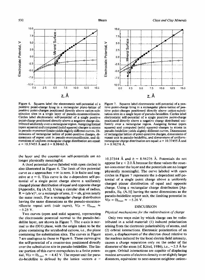
Figure 6 shows the electrostatic potential of a single pseudo-montmoril lonite counter-ion as a function o f the distance separating the phyllosilicate layer from the plane containing the counter-ions. The z-axis is taken to be normal to the (001) plane with the origin at the octahedral-cation plane (i.e., the plane containing the substitution sites). The curve labeled with open squares was computed by assigning formal charges to all the atoms in the layer, whereas the curve labeled with solid squares employed computed charges (cf. Table 1). Both of these curves approach - a o as z approaches zero, whereas at large z values, the curve becomes linear and thereby approaches +oo.
These two curves express the self-potential of a pos- itive point charge in a two-dimensional, infinite plane of positive point charges separated by a distance z from a single pseudo-montmoril lonite layer. Both the pos- itively charged counter-ions and the negatively charged
0.0
> -g , , . . , f -
In
0
s
I l l
> -0.5 g r
0 13. -1.0 o
s ~ -1.5
LLI
-2.0
Defect
Neutra l
/ m " ~ a r g e d
-1.0 -0.5 0.0
y/b 0.5 1.0
-1
-2
-3 ~ _
-4
- S , i
-1.0 -0.5
Neutral
Defect
J Charged
0.0 0.5 1.0
y/b Figure 5. Electrostatic potentials in (001) surface plane above phyllosilicate layers, 1.98 .~ above center of basal oxygens: (upper) octahedrally substituted pseudo-montmorillonite and (lower) tetrahedra11)~.~ubstituted pseudo-beidellite. "Charged" labels potentials along transect passing above substituted site of the given phyllosilicate. "Neutral" labels potentials above pyrophyllites, from which the two substituted minerals were derived (see text), along transects appropriate to position of the substitution. "Defect" labels potentials computed by sub- tracting the "neutral" curve from the "'charged" curve for each type of substitution.
substitution defect are arranged in a rectangular lattice (layer-lattice symmetry: p2mm) , with the positive charges lying directly above the negatively charged de- fects. The linear portion o f both pseudo-montmoril- lonite layer curves, which approaches + o f at large z, extrapolates to the finite potential, V(z = 0)L~yer ~" --4.98 V. The repeat unit for pseudo-montmoril lonite is de- fined by the lattice vectors: a = 10.37544 ~k, b = 8.98463 /k. Potentials for these two curves are not plotted for z < 5.0 ~ , because in that range the counter-ions enter
532 Bleam Clays and Clay Minerals
>
c"
0 13. 0
o "6
U.I
10.0 !
8 7.5 ~
5.0 CO
2.5 t -
O0
-2.5 ~
-5.0
-7.5
-10.0 0.0 2.5
f J J
5.0 7.5 10.0 12.5 15.0
z,A Figure 6. Squares label the electrostatic self-potential of a positive point-charge lying in a rectangular plane-lattice of positive point-charges positioned directly above cation-sub- stitution sites in a single layer of pseudo-montmorillonite. Circles label electrostatic self-potential of a single positive point-charge positioned directly above a negative charge dis- tributed uniformly over a rectangular region. Assigning formal (open squares) and computed (solid squares) charges to atoms in pseudo-montmoriUonite yields slightly different curves. Di- mensions of rectangular lattice of point-positive charges, di- mensions of repeat unit in pseudo-montmorillonite, and di- mensions of uniform-rectangular charge distribution are equal: a = 10.37455/~ and b = 8.98463/~.
>
t -
O
r
o
LIJ
I0.0 1 ! !
7.5 ,
5.0
2.5 03
-5.0 . ~ -7.5
! !
- I 0 .0
0.0 2.5 5.0
J o.,o----'--
J J
J
7.5 10.0 12.5 15.0
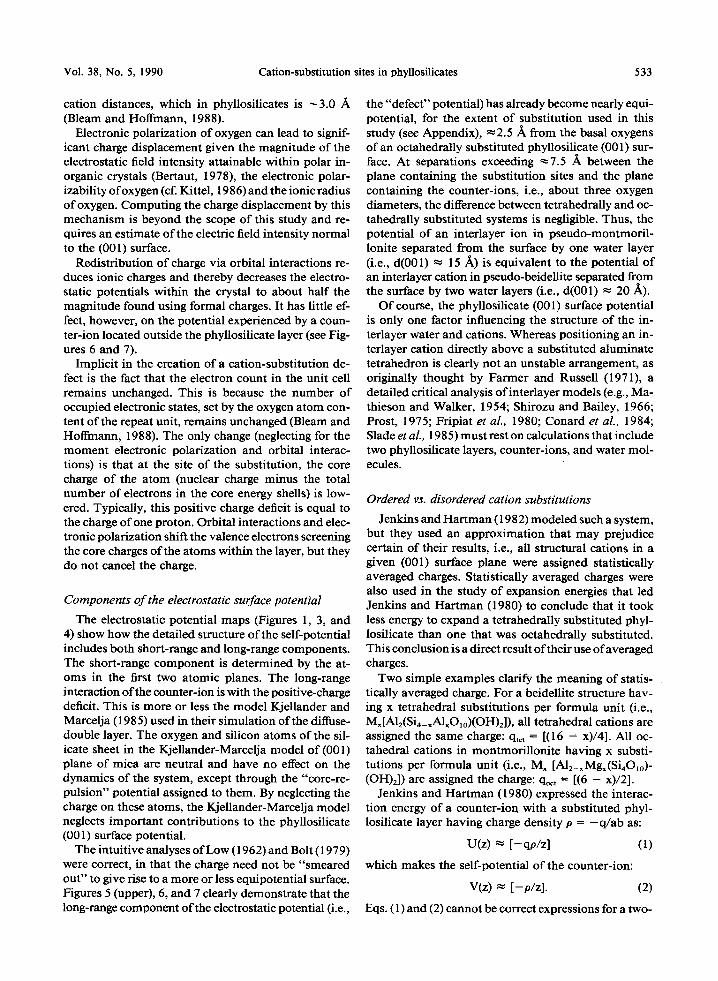
z,A Figure 7. Squares label electrostatic self-potential of a pos- itive point-charge lying in a rectangular plane-lattice of pos- itive point-charges positioned directly above cation-substi- tution sites in a single layer of pseudo-beidellite. Circles label electrostatic self-potential of a single positive point-charge positioned directly above a negative charge distributed uni- formly over a rectangular region. Assigning formal (open squares) and computed (solid squares) charges to atoms in pseudo-beidellite yields slightly different curves. Dimensions of rectangular lattice of point-positive charges, dimensions of repeat unit in pseudo-beidellite, and dimensions of uniform- rectangular charge distribution are equal: a = 10.37455 A and b = 8.96276 A.
the layer and the counter-ion self-potentials are no longer physically meaningful.
A third potential curve (labeled with open circles) is also illustrated in Figure 6. The limit of this potential curve as z approaches + ~ is zero. It is finite and neg- ative at z = 0. This curve is the z-dependent self-po- tential of a single point charge above a uniformly charged planar distribution of equal and opposite charge [Appendix, Eq (A.5)]. Using a circular disk of radius, R = (ab/Tr) '/', or a rectangle o f area, fl = ab, gives nearly the same result. For a rectangular charge distribution having the same dimensions as the pseudo-montmo- rillonite repeat unit (vide supra), V(z = 0)poi,t ~- - 5 . 2 5 V .
Two curves (open and solid squares), representing the electrostatic potential normal to the pseudo-bei- dellite layer, are shown in Figure 7. The z-axis is nor- mal to the (001) plane, with the origin taken to be the plane containing the tetrahedral cations, i.e., the plane containing the substitution sites. The curves in Figure 7 are analogous to those in Figure 6. These curves give the self-potential of a counter-ion positioned directly over the substitution site in pseudo-beidellite. The lin- ear portion o f this curve extrapolates to a finite poten- tial, V(z = 0)L~yer ~ --4.42 V. The repeat unit for pseu- do-beidellite is defined by the lattice vectors a =
10.37544 A and b = 8.96276 ]~. Potentials do not appear for z < 2.0 A because for these values the coun- ter-ions enter the layer and the potentials are no longer physically meaningful. The curve labeled with open circles in Figure 7 represents the z-dependent self-po- tential of a single point charge above a uniformly charged planar distribution of equal and opposite charge. Using a rectangular charge distribution [Ap- pendix, Eq. (A.5)] having the same dimensions as the pseudo-beidellite repeat unit, the limiting potential is: V(z = 0)poi,, ~ - 5 . 2 6 V.
DISCUSSION
Physical mechanisms for the redistribution of charge
Only two ways exist by which charge can be redis- tributed in a solid material: (1) induced polarization arising from the electronic polarizability of atoms, and (2) orbital interactions. Electronic polarization of an atom, a displacement of the electron cloud relative to the nucleus induced by the local electric field intensity, causes a charge separation only on the order of the diameter of the atom (cf. Kittel, 1986), i.e., ~2.5 ,~ for oxygen. Orbital interactions are capable of displacing modest amounts of electron density over slightly larger distances, equivalent to next-nearest neighbor cat ion-
Vol. 38, No. 5, 1990 Cation-substitution sites in phyllosilicates 533
cation distances, which in phyllosilicates is ~3.0 A (Bleam and Hoffmann, 1988).
Electronic polarization of oxygen can lead to signif- icant charge displacement given the magnitude of the electrostatic field intensity attainable within polar in- organic crystals (Bertaut, 1978), the electronic polar- izability of oxygen (cf. Kittel, 1986) and the ionic radius of oxygen. Computing the charge displacement by this mechanism is beyond the scope of this study and re- quires an estimate of the electric field intensity normal to the (001) surface.
Redistr ibution of charge via orbital interactions re- duces ionic charges and thereby decreases the electro- static potentials within the crystal to about half the magnitude found using formal charges. It has little ef- fect, however, on the potential experienced by a coun- ter-ion located outside the phyllosilicate layer (see Fig- ures 6 and 7).
Implici t in the creation of a cation-substi tution de- fect is the fact that the electron count in the unit cell remains unchanged. This is because the number of occupied electronic states, set by the oxygen a tom con- tent of the repeat unit, remains unchanged (Bleam and Hoffmann, 1988). The only change (neglecting for the moment electronic polarization and orbital interac- tions) is that at the site o f the substitution, the core charge o f the a tom (nuclear charge minus the total number of electrons in the core energy shells) is low- ered. Typically, this positive charge deficit is equal to the charge of one proton. Orbital interactions and elec- tronic polarization shift the valence electrons screening the core charges o f the atoms within the layer, but they do not cancel the charge.
Components o f the electrostatic surface potential
The electrostatic potential maps (Figures 1, 3, and 4) show how the detailed structure o f the self-potential includes both short-range and long-range components. The short-range component is determined by the at- oms in the first two atomic planes. The long-range interaction o f the counter-ion is with the positive-charge deficit. This is more or less the model Kjellander and Marcelja (1985) used in their s imulation of the diffuse- double layer. The oxygen and silicon a toms o f the sil- icate sheet in the Kjel lander-Marcelja model of (001) plane of mica are neutral and have no effect on the dynamics of the system, except through the "core-re- pulsion" potential assigned to them. By neglecting the charge on these atoms, the Kjellander-Marcelja model neglects important contributions to the phyllosilicate (001) surface potential.
The intuit ive analyses o f Low (1962) and Bolt (1979) were correct, in that the charge need not be "smeared out" to give rise to a more or less equipotential surface. Figures 5 (upper), 6, and 7 clearly demonstrate that the long-range component of the electrostatic potential (i.e.,
the "defect" potential) has already become nearly equi- potential, for the extent of substitution used in this study (see Appendix), ~2.5 A from the basal oxygens of an octahedrally substituted phyllosilicate (001) sur- face. At separations exceeding ~7.5 ik between the plane containing the substitution sites and the plane containing the counter-ions, i.e., about three oxygen diameters, the difference between tetrahedrally and oc- tahedrally substituted systems is negligible. Thus, the potential of an interlayer ion in pseudo-montmori l - lonite separated from the surface by one water layer (i.e., d(001) ~ 15 ]k) is equivalent to the potential o f an interlayer cation in pseudo-beidellite separated from the surface by two water layers (i.e., d(001) ~ 20 ~).
Of course, the phyllosilicate (001) surface potential is only one factor influencing the structure o f the in- terlayer water and cations. Whereas posit ioning an in- terlayer cation directly above a substituted aluminate tetrahedron is clearly not an unstable arrangement, as originally thought by Farmer and Russell (1971), a detailed critical analysis of interlayer models (e.g., Ma- thieson and Walker, 1954; Shirozu and Bailey, 1966; Prost, 1975; Fripiat et aL, 1980; Conard et aL, 1984; Slade et al., 1985) must rest on calculations that include two phyllosilicate layers, counter-ions, and water mol- ecules.
Ordered vs. disordered cation substitutions
Jenkins and Har tman (1982) modeled such a system, but they used an approximat ion that may prejudice certain of their results, i.e., all structural cations in a given (001) surface plane were assigned statistically averaged charges. Statistically averaged charges were also used in the study of expansion energies that led Jenkins and Har tman (1980) to conclude that it took less energy to expand a tetrahedrally substituted phyl- losilicate than one that was octahedrally substituted. This conclusion is a direct result of their use o f averaged charges.
Two simple examples clarify the meaning of statis- tically averaged charge. For a beidellite structure hav- ing x tetrahedral substitutions per formula unit (i.e., Mx[A12(Si4_xAlxO~o)(OH)2]), all tetrahedral cations are assigned the same charge: q,e, = [(16 - x)/4]. All oc- tahedral cations in montmori l loni te having x substi- tutions per formula unit (i.e., Mx [AI2_xMg,(Si40~o)- (OH)2]) are assigned the charge: qo~t = [(6 - x)/2].
Jenkins and Har tman (1980) expressed the interac- t ion energy of a counter-ion with a substituted phyl- losilicate layer having charge density p = - q / a b as:
U(z) ~ [ -qp /z ] (1)
which makes the self-potential o f the counter-ion:
V(z) ~ I -o /z] . (2)
Eqs. (1) and (2) cannot be correct expressions for a two-

534 Bleam Clays and Clay Minerals
dimensional, infinite layer of charges. The limit as z approaches + oo should be + oo (see Fripiat et aL, 1977; Watson et al., 1981), whereas the limit as z approaches zero should be a negative but finite value [see Eq. (A.5)]. Eq. (2) fails at both limits.
In the configuration used by Jenkins and Hartman (1980), either all of the charge is in one rectangular region (Oo~t = - q / a b ) at a distance zo~t = l + d from the counter-ion (i.e., octahedral substitution) or the charge density is equally spread over two rectangular regions (Pte~. ~ =Ptet. 2 = -q /2ab ) at distances z~et. ~ = l and z,,,. 2 = l + 2d (i.e., tetrahedral substitution). In the Jenkins and Har tman (1980) model of tetrahedral substitution, a particular counter-ion can be in close contact with only one of the two regions, the closest approach to the remaining half of the layer charge being z = 2d. The counter-ion of an octahedrally substituted phyllosilicate is always found at a lower potential rel- ative to the counter-ion of a tetrahedrally substituted phyllosilicate using the Jenkins and Hartman (1980) charge distribution. Using either Eq. (A.2) or Eq. (A. 5), this consequence of using averaged charges can be ver- ified.
In reality, the charge is not averaged over all cations, there being no physical basis for such an averaging. Counter-ions at a given hydration state can always ap- proach a tetrahedral site more closely than an octa- hedral site and thus attain a more negative electrostatic potential.
Lewis basicity o f basal oxygens
Sposito (1984, 1989) discussed the character of the phyllosilicate (001) surface cation-substitution sites in terms of the siloxane cavity, i.e., the 6-fold rings in the tetrahedral sheet. The basal oxygens in the 6-fold ring unquestionably present a geometry suitable for cation coordination, yet crystal structure refinements of hy- drated vermiculite (Mathieson and Walker, 1954; Shi- rozu and Bailey, 1966; Slade et aL, 1985) indicate that interlayer cations commonly lie above the substituted tetrahedra. The nature of the electrostatic potential at the (001) surface is probably more important than the geometry of the 6-fold ring in determining the posi- tioning of the interlayer cation.
The Sposito (1984, 1989) model also considers the Lewis base character of the basal oxygens. The bond- strength sum for basal oxygens bridging aluminate and silicate tetrahedra is ~'o = 1.8 valence units (Pauling, 1929). The bond strength sum of basal oxygens in oc- tahedrally substituted phyllosilicates does not differ from the bond strength sum for basal oxygens in py- rophyllite and talc because cation substitutions affect only those cation-oxygen bonds within the coordina- tion polyhedra containing the substituting cation. The electrostatic valence principle and valence bond theory (Pauling, 1929; Brown, 1978) predict that the Lewis
character of neutral and octahedrally substituted phyl- losilicates should be comparable.
Brown (1978) assigned ~0.2 valence units to the O-.- H bond of an oxygen receiving a normal hydrogen bond. The Lewis basicity of basal oxygens ranges from that found in neutral-layer and octahedrally substituted phyllosilicates to that found in tetrahedrally substitut- ed phyllosilicates. The basal-oxygen basicity in the for- mer is so weak that the oxygens cannot effectively re- ceive a hydrogen bond (i.e., g'o = 2.0 valence units), whereas the aluminate oxygens in the latter would rank as good hydrogen bond receptors. Increased Lewis base strength of aluminate oxygens results from the in- creased electron population in tetrahedral oxygens co- ordinating a luminum, estimated to be ~ 12% relative to pyrophyllite or talc (Bleam and Hoffmann, 1988). Electronic polarization (vida supra) produces no vari- ation in the Lewis basicity of basal oxygens, because it is no more than a shift in the center of gravity of charge.
Electrostatic field intensity f lux
Potentials are additive, allowing a separation of the "charged-layer" potential into "neutral-layer" and "defect" components. The "charged-layer" potential is most easily viewed as a "neutral-layer" potential perturbed by a "defect" potential. The flux of the elec- trostatic field intensity increases as the distance sepa- rating the test charge and the substitution site de- creases. The nonuniformity of the flux in the (001) surface is more pronounced at small separations. The relation between the electrostatic field intensity flux and charge separation is expressed in the electrostatic potential maps as a distortion of the "neutral-layer" potential caused by the cation-substitution defect. The distortion of the electrostatic potential is more extreme for tetrahedral substitution than for octahedral substi- tution. In other words, as the substitution site is ap- proached, the number of electrostatic field lines per unit area increases. What has been described as "lo- calized charge" (Farmer, 1978; Sposito, 1984; Odom, 1984; McBride, 1989) is more correctly termed "in- creased electrostatic field flux."
Negative potentials in the (001) plane occur not be- cause the layer charge is localized on the basal oxygens, but rather because the surface oxygens producing those potentials are not screened. The notion that cation sub- stitution causes negative charge to reside on the basal oxygens is inaccurate. Consider the difference between the curves due to computed (open squares) and formal (solid squares) charges in Figures 6 and 7. This differ- ence in counter-ion electrostatic self-potentials for these two alternatives for assigning ion charges arises from differences in the charge distribution at the defect. If formal charges are used, the cation-substitution defect consists of a point positive-charge deficit at the sub-
Vol. 38, No. 5, 1990 Cation-substitution sites in phyllosilicates 535
s t i tu t ion site, t he charges on the oxygen a t o m s r e m a i n u n c h a n g e d in th i s s u b s t i t u t i o n mode l . T h e po ten t i a l us ing c o m p u t e d charges (Tab le 1) r ep resen t s a subs t i - t u t i o n mode l , in w h i c h the defect is ac tual ly a n ar ray o f charges cons i s t ing o f a par t ia l charge a t the subs t i - t u t i o n site, w i th the r e m a i n d e r ass igned to the oxygens i m m e d i a t e l y s u r r o u n d i n g it a n d the ca t ions nex t -nea r - est n e i g h b o r s to t h a t site. A l t h o u g h the po ten t i a l s ex- pe r i enced by the a t o m s w i t h i n the phyl los i l ica te layer are subs tan t i a l ly different in the two mode ls , the coun- t e r - ion po ten t i a l s are v i r tua l ly ident ical .
A P P E N D I X
Mineral structures
The pseudo-hectorite (Mx [Mg3_xLix(Si40,o)(OH)2], x = 0.25) structure was derived from the refinement of talc by Perdi- katsis and Burzlaff(1981). The pseudo-montmorillonite (Mx' [Al2_xMgx(Si,O,o)(OH)2], x = 0.25) and pseudo-beidellite (M x. [A12(Sia_xAlxO~o)(OH)2], x = 0.25) structures were derived from the refinement of pyrophyllite by Lee and Guggenheim (1981). Tetrahedral rotation was 11 ~ in both derivations.
The tetrabedra of the silicate sheets have point group sym- metry 43m; the octahedra are flattened and have point group symmetry 3m. Neglecting cation order, the layers themselves have layer group symmetry c2/m, whereas the tetrahedral sheets have layer group symmetries p6mm, p3m 1 and cl m 1 in pseudo-hectorite, pseudo-montmorillonite and pseudo- beidellite, respectively. Important distances inpseudo-hec- torite are: d(Si--O) = 1.625/k; d(X-O) = 2.098/~; d(O-H) = 0.864 ~ (X = Mg, Li). Important distances in pseudo-mont- morillonite and pseudo-beidellite are: d(T--O) = 1.618/~; cl(X- O) = 1.912/~; d(O-H) = 0.864/~ (T = Si, A1; X = Mg, AI).
The tetrahedra are tilted 4", as found by Lee and Guggen- heim (1981), in tetrahedral sheet of pseudo-beidellite. The tetrahedra in pseudo-montmorillonite are not tilted because even in celadonite both octahedral sites are the same size (Bailey, 1975; Weiss et aL, 1985).
Electrostatic potential functions
I ra charge, - q , is uniformly distributed over a circular disk of radius R, the charge density per unit area is: O = -q/~rR2. The electrostatic potential at a position z above the center of this charge distribution is:
V(z) = (p/4~r~o) [r(z ~ + r~)-"q dr dO (A.1)
V(z) = (O/4r + 2r(z 2 + R2) '/2] (A.2)
V(z = 0) = (O/4~r~o)[27rR ] = -q/(27rcoR). (A.3)
If a charge, - q , is uniformly distributed over a rectangle of dimensions a and b, the charge density per unit area is: p = - q / a b . The electrostatic potential at a position z above the center of this charge distribution is:
f_w2f~2 V'(z) = (p/41reo) [x 2 + y2 + z2)-,/q dx dy. (A.4) b / 2 a / 2
Integrating and simplifying using the function f(z) = (a2/4 + b2/4 § z2) '/' yields:
V'(z) = (p/41reo){2zarctan[(-a/2 - b/2 + f(z))/z] - 2z arctan[(a/2 - b/2 + f(z))/z] - 2z arc tan[( -a /2 + b/2 + f(z))/z] + 2z arctan[(a/2 + b/2 + f(z))/z]
- b l n [ - a / 2 + f(z)] + bin[a/2 + f(z)] - a l n [ - b / 2 + f(z)] + aln[b/2 + f(z)]},
(A.5)
and
V'(z = 0) = (p/4~reo){-bln[-a/2 + f(0)] + bin[a/2 + f(0)]
- a l n [ - b / 2 + f(0)] + aln[b/2 + frO)]}. (A.6)
The limit as z ~ to for both Eq. (A.2) and Eq. (A.5) is clearly zero, as expected. These potential functions show that a single point charge in contact with a uniform planar charge distribution is at a finite potential, the exact value of which depends on both the area and the configuration of the uniform planar charge.
R E F E R E N C E S
Bailey, S. W. (1975) Cation ordering and pseudosymmetry in layer silicates: A met. Mineral. 60, 175-187.
Bafios, J. O. (1985) Interlayer energy for partial slip and cleavage in muscovite: Philos. Mag. A 52, 145-152.
Bertaut, E. F. (1978) Electrostatic potentials, fields and field gradients: J. Phys. Chem. Solids 39, 97-102.
Bleam, W. F. and Hoffmann, R. (1988) Isomorphous sub- stitution in phyllosilicates as an electronegativity pertur- bation: Its effect on bonding and charge distribution: Phys. Chem. Minerals 15, 398-408.
Bolt, G .H. (1979) The ionic distribution in the diffuse dou- ble layer: in Soil Chemistry B. Physico-Chemical Models, G. H. Bolt, ed., Elsevier, Amsterdam, 1-25.
Brown, I. D. (1978) Bond valences--A simple structural model for inorganic chemistry: Chem. Soc, Rev. 7, 359- 376.
Conard, J., Estrade-SzwarckopfH., Dianoux, A. J., and Poin- signon, C. (1984) Water dynamics in a planar lithium hydrate in the interlayer space of a swelling clay. A neutron scattering study: J. Phys. 45, 1361-1371.
Farmer, V. C. (1978) Water on particle surfaces: in The Chemistry of Soil Constituents, D. J. Greenland and M. H. B. Hayes, eds., Wiley, New York, 405-448.
Farmer, V. C. and Russell, J. D. (1971) Interlayer complexes in layer silicates. The structure of water in lamenar ionic solutions: Trans. Faraday Soc. 67, 2737-2749.
Foot, J .D. andColburn, E.A. (1988) Electrostatic potentials for surfaces of inorganic and molecular crystals: J. Mol. Graphics 6, 93-99.
Fripiat, J. G., Lucas, A. A., Andr6, J. M., and Derouane, E. G. (1977) On the stability of polar surface planes of mac- roscopic ionic crystals: Chem. Phys. 21, 101-104.
Fripiat, J. J., Kadi-Hanifi, M., Conard, J., and Stone, W. E. E. (1980) NMR study of adsorbed water--III. Molecular orientation and protonic motions in the one-layer of a Li hectorite: in Magnetic Resonance in Colloid and Interface Science, J. P. Fraissard and H. A. Resing, eds., Reidel, Boston, 529-535.
Giese, R. F. (1979) Hydroxyl orientations in 2:1 phyUosil- icates: in Clays and Clay Minerals, Proc. 13th Natl. Conf., Madison, Wisconsin, 1964, W. F. Bradley and S. W. Bailey, eds., Pergamon Press, New York, 105-144.
Giese, R. F. (1984) Electrostatic energy models of micas: Rev. Mineral. 13, 105-144.
Heyes, D. M. and van Swol, F. (1981) The electrostatic potential and field in the surface region of lamina and semi- infinite point charge lattices: J. Chem. Phys. 75, 5051-5058.
Hoffmann, R. (1963) An extended Hiickel theory. I. Hy- drocarbons: J. Chem. Phys. 39, 1397-1412.
Hoffmann, R. and Lipscomb, W. N, (1962) Theory ofpoly-
536 Bleam Clays and Clay Minerals
hedral molecules. I. Physical factorizations of the secular equation: J. Chem. Phys. 36, 2179-2189.
Jenkins, H. D. B. and Hartman, P. (1979) A new approach to the calculation of electrostatic energy relations in min- erals: The dioctahedral and trioctahedral phyllosilicates: Philos. Trans. Royal Soc. London Ser. A 293, 169-208.
Jenkins, H. D. B. and Hartman, P. (1980) Application of a new approach to the calculation of electrostatic energies of expanded di- and trioctahedral micas: Phys. Chem. Min- erals 6, 313-325.
Jenkins, H. D. B. and Hartman, P. (1982) Calculations on a model intercalate containing a single layer of water mol- ecules: A s tudy of po tass ium vermicul i te , K2~Mg6- (Si4_xAl~)2020(OH)4, for 1 -< x < 0: Philos. Trans. Royal Soc. London Ser. A 304, 397-446.
Kittel, C. (1986) Introduction to Solid State Physics: 6th ed., Wiley, New York, 646 pp.
Kjellander, R. and Marcelja, S. (1985) Polarization of water between molecular surfaces: A molecular dynamics study: Chemica Scripta 25, 73-80.
Lee, J. J. and Guggenheim, S. (1981) Single crystal x-ray refinement of pyrophyllite-1 Tc: Amer. Mineral. 66, 350- 357.
Lee, W. W. and Choi, S.-I. (1980) Determination of the Madelung potential of ionic crystals with a polar surface by the Ewald method: J. Chem. Phys. 72, 6164-6168.
Low, P.F. (1962) Influence of adsorbed water on exchange- able ion movement: in Clays and Clay Minerals, Proc. 9th Natl. Conf., West Lafayette, Indiana, 1960, Ada Swineford, ed., Pergamon Press, New York, 219-228.
Mathieson, A. McL. and Walker, G. F. (1954) Crystal struc- ture of magnesium-vermiculite: Amer. Mineral. 39, 231- 255.
McBride, M. B. (1989) Surface chemistry of soil minerals: in Minerals in Soil Environments: 2nd ed., J. B. Dixon and S. B. Weed, eds., Soil Science Society of America, Madison, Wisconsin, 35-87.
Odom, I. E. (1984) Smectite clay minerals: Properties and uses: Philos. Trans. Royal Soc. London Set. A 311, 391- 409.
Parry, D.E. (1975) The electrostatic potential in the surface region of an ionic crystal: Surface Sci. 49, 433-440.
Parry, D. E. (1976) Errata: The electrostatic potential in the surface region of an ionic crystal: Surface Sci. 54, 195.
Pauling, L. (1929) The principles determining the structure of complex ionic crystals: J. Amer. Chem. Soc. 51, 1010- 1026.
Perdikatsis, B. and Burzlaff, H. (1981) Strukturverfeinertmg am Talk Mg3[(OH)2Si4Olo]: Z. Kristallogr. 156, 177-186.
Prost~ R. (1975) Interactions between adsorbed water mol- ecules and the structure of clay minerals: Hydration mech- anism of smectites: in Proc. Int. Clay Conf., Mexico City, 1975, S. W. Bailey, ed., Applied Publishing, Wilmette, Il- linois, 351-359.
Shirozu, H. and Bailey, S. W. (1966) Crystal structure of a two-layer Mg-vermiculite: Amer. Mineral. 51, 1124-1143.
Slade, P. G., Stone, P. A., and Radoslovich, E. W. (1985) Interlayer structures of the two-layer hydrates of Na- and Ca-vermiculites: Clay & Clay Minerals 33, 51-61.
Smith, E. R. (1983) Electrostatic potential at a plane surface of a point ionic crystal: Physica 120A, 327-338.
Sposito, G. (1984) The Surface Chemistry of Soils, Oxford University Press, New York, 234 pp.
Sposito, G. (1989) Surface reactions in natural aqueous col- loidal systems: Chimia 43, 169-176.
Sposito, G. and Prost, R. (1982) Structure of adsorbed water on smectites: Chem. Rev. 82, 553-573.
Veitch, L. G. and Radoslovich, E. W. (1963) The cell di- mensions and symmetry of layer-lattice silicates. III. Oc- tahedral ordering: Amer. Mineral. 48, 62-75.
Watson, R. E., Davenport, J. W., Perlman, M. L., and Sham, T .K . (1981) Madelung effects at crystal surfaces: Impli- cations for photoemission: Phys. Rev. B 24, 1791-1797.
Weiss, Z., Rieder, M., Chmielova, M., and Krajicek, J. (1985) Geometry of the octahedral coordination in micas: A re- view of refined structures: Amer. Mineral. 70, 747-757.
Whangbo, M.-H., Hoffmann, R., and Woodward, R. B. (1979) Conjugated one and two dimensional polymers: Proc. Royal Soc. London Ser. A 366, 23-46.
(Received 24 January 1990; accepted 6 June 1990; Ms. 1979)