the national shipbuilding research …9500 macarthur blvd bldg 192 room 128,bethesda,md,20817-5700...
TRANSCRIPT

SHIP PRODUCTION COMMITTEEFACILITIES AND ENVIRONMENTAL EFFECTSSURFACE PREPARATION AND COATINGSDESIGN/PRODUCTION INTEGRATIONHUMAN RESOURCE INNOVATIONMARINE INDUSTRY STANDARDSWELDINGINDUSTRIAL ENGINEERINGEDUCATION AND TRAINING
THE NATIONALSHIPBUILDINGRESEARCHPROGRAM
September 1989NSRP 0310
1989 Ship Production Symposium
Paper No. 2: Producibility in U.S. Navy Ship Design
U.S. DEPARTMENT OF THE NAVYCARDEROCK DIVISION,NAVAL SURFACE WARFARE CENTER

Report Documentation Page Form ApprovedOMB No. 0704-0188
Public reporting burden for the collection of information is estimated to average 1 hour per response, including the time for reviewing instructions, searching existing data sources, gathering andmaintaining the data needed, and completing and reviewing the collection of information. Send comments regarding this burden estimate or any other aspect of this collection of information,including suggestions for reducing this burden, to Washington Headquarters Services, Directorate for Information Operations and Reports, 1215 Jefferson Davis Highway, Suite 1204, ArlingtonVA 22202-4302. Respondents should be aware that notwithstanding any other provision of law, no person shall be subject to a penalty for failing to comply with a collection of information if itdoes not display a currently valid OMB control number.
1. REPORT DATE SEP 1989 2. REPORT TYPE
3. DATES COVERED 00-00-1989 to 00-00-1989
4. TITLE AND SUBTITLE The National Shipbuilding Research Program. 1989 Ship ProductionSymposium, Paper No. 2: Producibility in U.S. Navy Ship Design
5a. CONTRACT NUMBER
5b. GRANT NUMBER
5c. PROGRAM ELEMENT NUMBER
6. AUTHOR(S) 5d. PROJECT NUMBER
5e. TASK NUMBER
5f. WORK UNIT NUMBER
7. PERFORMING ORGANIZATION NAME(S) AND ADDRESS(ES) Naval Surface Warfare Center CD,Code 2230 -Design IntegrationTower,9500 MacArthur Blvd Bldg 192 Room 128,Bethesda,MD,20817-5700
8. PERFORMING ORGANIZATIONREPORT NUMBER
9. SPONSORING/MONITORING AGENCY NAME(S) AND ADDRESS(ES) 10. SPONSOR/MONITOR’S ACRONYM(S)
11. SPONSOR/MONITOR’S REPORT NUMBER(S)
12. DISTRIBUTION/AVAILABILITY STATEMENT Approved for public release; distribution unlimited
13. SUPPLEMENTARY NOTES
14. ABSTRACT
15. SUBJECT TERMS
16. SECURITY CLASSIFICATION OF: 17. LIMITATION OF ABSTRACT
18. NUMBEROF PAGES
21
19a. NAME OFRESPONSIBLE PERSON
a. REPORT unclassified
b. ABSTRACT unclassified
c. THIS PAGE unclassified
Standard Form 298 (Rev. 8-98) Prescribed by ANSI Std Z39-18

DISCLAIMER
These reports were prepared as an account of government-sponsored work. Neither theUnited States, nor the United States Navy, nor any person acting on behalf of the UnitedStates Navy (A) makes any warranty or representation, expressed or implied, with respectto the accuracy, completeness or usefulness of the information contained in this report/manual, or that the use of any information, apparatus, method, or process disclosed in thisreport may not infringe privately owned rights; or (B) assumes any liabilities with respect tothe use of or for damages resulting from the use of any information, apparatus, method, orprocess disclosed in the report. As used in the above, “Persons acting on behalf of theUnited States Navy” includes any employee, contractor, or subcontractor to the contractorof the United States Navy to the extent that such employee, contractor, or subcontractor tothe contractor prepares, handles, or distributes, or provides access to any informationpursuant to his employment or contract or subcontract to the contractor with the UnitedStates Navy. ANY POSSIBLE IMPLIED WARRANTIES OF MERCHANTABILITY AND/ORFITNESS FOR PURPOSE ARE SPECIFICALLY DISCLAIMED.


ABSTRACT
Recent NAVSEA studies of a twinskeg hull form design applied to aT-AO type ship indicated many areasof possible improvement in produci-bi l i ty .
This paper reviews the findingsof producibility studies and at-tempts to indicate specific areaswhere an improvement in producibili-ty and attendant cost savings forNavy ships are possible without anydegradation in ship performance andsurvivability.
Most available studies on pro-ducibility have an inherent trait ofelaborating on details of shipyardproducibility. This paper attemptsto confine itself to the produci-bility aspect of the design phase,ending with the completion of con-tract design. While it is of coursenecessary for the Navy ship designerto know about producibility detailsof prospective building yards, hemust be careful not to incorporateany details that may be restrictiveon some of the prospective buildersand thereby hinder competition.
Although the application of atwin skeg hull form to the ongoingT-AO program was determined byNAVSEA not to be practicable becauseof the advanced status of the shipacquisition program, it was deter-mined that the concept of the produ-cible, designed-to-build ship wasworth further investigation for in-corporation into future designs be-cause of potential cost savings.
The paper concludes with recom-mendations for a method of applica-tion of producibility to the Navyship design process for MSC-operatedT-Ships.
INTRODUCTION
Producibility is defined as thecapability to manufacture, build orassemble goods in a most cost-efficient manner. For this paper,producibility in the pure sense willhave to be subdivided as requiredfor the unique characteristics ofnaval ship design. The normal ap-proach to the design of highly effi-cient details of construction cannotalways be fully applied to navalship design since the Navy’s designactivity stops at Contract Designcompletion, and it is not known atthis point which of the prospectiveshipbuilders w i l l be awarded thecontract. The application of produ-cibi l i ty to naval ship design isfurther complicated by the fact thatthere are usually fixed, and un-changeable mission requirementswhich are taboo and cannot be modi-fied for any reason.
This paper examines whichaspects of producibility are applic-able equally to the range of pros-pective builders and can thereforebe incorporated in a Navy shipdesign. The application of produci-bi l i ty is discussed in three seg-ments: Feasibility Studies, Preli-minary Design, and Contract Design.
PRODUCIBILITY FOR NAVAL SHIPS
Applying producibility to U.S.Navy ships is di f ferent than theapplication to commercial ship de-signs, considering that any Navyship design must comply with theprocurement methods and rules thathave to be followed by governmentagencies. This means that the tech-nical configuration and data in abid package must permit all prospec-tive builders to bid on the procure-ment in a fair and even competition.Maximum producibility would requirea ship to be designed for construc-tion in a specific predeterminedproduction facility.
2-1

Producibility for Surface Combatants
A naval combatant’s primaryfunctions have priority over normaleconomy and producibility considera-tions in order not to degrademission effectiveness. For example,high-speed small size and advancednaval surface combatants are usuallyweight sensitive and cannot normallytolerate the small weight increasesassociated with producibility con-siderations without a deteriorationin their mission effectiveness. Forthese ships, it is, therefore, ofthe utmost importance to considerproducibility and the attendant ben-efits and penalties during theearliest feasibility study phases.This approach minimizes performancedecline and makes it possible todevelop some general guidelines forthe application of tempered pro-ducibility for these vessels.
Producibility for T-Ship Designs
T-ships are usually designed tocommercial requirements with the ex-ception of certain. “fenced” areasfor mission-critical systems. Theseareas depend on the ship type andmission, and are usually invoked byvery detailed specificationlanguage. T-ships are usually rela-tively slow speed vessels (20 knotsor less) which are somewhat akin tocomparable commercial vessels andare therefore not as sensitive tothe slightly greater weight usuallyassociated with a producible shipdesign. The Navy’s damaged stabil-ity criteria, as applied to T-ships,
not conducive to producibilitydue to limitations on compartmentlength.
Producibility in General
Primarily, this paper primarilyinvestigates the application ofproducibility to commercial-like,“T-Ship design,” since that isapparently the area where the mostbenefit may be obtained. To applyproducibility, one must obviouslyfirst know the number of ships to bebuilt, since the design effortexpended to obtain a producible shipvaries directly with the number ofships to be built. Only a minimaleffort is justified when one ship isbuilt from the design and a muchlarger effort can be made as thenumber of units to be built in-creases until the economy of scalecurve levels off. The discussion ofproducibility is subdivided intoFeasibility Studies, PreliminaryDesign, and Contract Design phases.The most benefit can be gained inthe early feasibility stage and the
least benefits are obtained in thelater phase of Contract Design. Themaximum effort must therefore be ex-pended in the early design stages.In other words, the return forproducibility efforts is maximum inthe beginning of the design projectand declines to a minimum as thedesign matures at the end of Con-tract Design. The return from pro-ducibility efforts increases againduring the Detail Design effort dueto shipyard appiied erection jointsand details of assembly. A possiblegeneral approach to producibility innaval ship design would be:
1) determine the number of shipsto be built;
2) determine the possible range ofprospective U.S. shipbuildersand their individual productionmethodology and facilities; and
3) determine ship size and com-partmentation by evaluatingstability, mission require-ments, and producibility con-siderations such as -framespacing, plate thickness, andpossible erection joint loca-tions to suit all prospectivebuilders.
PRODUCIBILITY IN NAVSEA
Background
The Naval Sea Systems Command(NAVSEA) has a long history of con-sidering producibility in conjunc-tion with ship design. For example,producibility improvement has been aserious concern in the design stagesfor the T-AO 187 and DDG 51. Asrecently as 1985, the NAVSEA NavalArchitecture Subgroup (SEA 55W) pro-posed a Twin-Skeg Integrated-Hulldesign concept (2) (references arelisted at the end of the paper) asan alternate ship design for theT-AO 187 program. This alternatedesign incorporated some unique hullform characteristics and certaindesign-to-build features. The pro-ducibility features considered wereas follows:
o Maximized areas of flatplate.
o Maximized areas of singlecurvature, for remainingshell plating.
o Increased frame spacingand reduced numbers ofpiece parts in structuralassembles.
2-2
o Standardized brackets andweb frames, and use ofbilge brackets in lieu oflongitudinal stringers inthe bilge turn area.
o Carefully arranged erec-tion joints.
The intent of the Twin-SkegIntegrated Hull Design for the T-AOwas to achieve procurement cost sav-ings with an integrated hull form,basic arrangement, and structuralconfiguration which were aimed atimproved producibility. Simultane-ously, the Twin-Skeg T-AO designprovided equal (or better) ship per-formance and intact and damagedstability characteristics, relativeto that achieved with the existingT-AO 187. The evaluations presentedbelow emphasize the analyses of theproducibility concepts which may af-fect the ship general naval archi-tectural characteristics and per-formance, particularly in the areasof intact and damaged ship sta-bility, and the producibility“lessons learned.n The hydrodynamicperformance of the Twin-Skeg T-AOdesign (including powering/fuel con-sumption, and seakeeping and maneu-vering performance) is the subjectof another paper (1) and is notdiscussed herein.
Twin-Skeg T-AO Design & General De-scription
The same general constraintsand requirements that applied to theT-AO 187 were also applied to theTwin-Skeg T-AO hull. These con-straints included general hull para-meters, namely length, depth, draft,beam, speed/power, cargo capacity,deck arrangements, and major water-tight subdivision. The Top LevelRequirements (TLR) for the T-AO 187was also applied to the Twin-SkegT-AO configuration.
The T-AO 187 Class Fleet Oilerhas been designed with the maximumutilization of commercial standardsexcept for the following systemsareas, which were subject to U.S.Navy design standards:
UNREPCargo HandlingVERTRHPDegaussingNavy Communications Electrical DistributionPhilosophySteering GearNixieHelicopter PlatformHelicopter Control Station
The application of the proposedalternate hull form to the -T-AO 187 ,.-Class Fleet Oiler program had to beaccomplished in a relatively shorttime. To save time, NAVSEA decidedto utilize the existing deckhouse,weatherdeck arrangements and UNREParrangement, and concentrate effortsin the areas affected by the pro-posed alternate hull form.
DESIGN CONSTRAINTS
Hull Form Design and Appendages
The final hull form of theTwin-Skeg T-AO design was basicallyderived from the material presentedin (3), with the addition of aNAVSEA-designed bulbous bow. Theproposed Twin Skeg T-AO design hasthe following distinctive featureswhen compared to the existing T-AO187 design:
The
Maximum utilization offlat or single curvatureplating, except for thebulbous bow and the twinskegs;
Twin side skegs, extendingfrom near amidships toabout station 19;
Two 26-foot diameter, slowturning (60 rpm) skewedpropellers;
A large, Nabla-type bulb-OUS bow;
A relatively large stemradius and soft shoulder;
A wave-knife stem;
Larger frame spacing;
Use of flat bars wherepossible in lieu of anglesor tees.
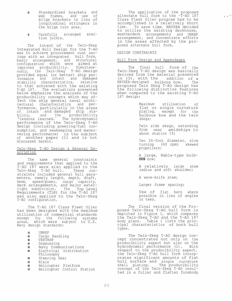
final version of the Pro-posed Twin-Skeg T-AO hull form isdepicted in Figure 1, which comparesthe Twin-Skeg T-AO and the T-AO 187body plans. Table 1 lists the prin-cipal characteristics of both hulltypes.
The Twin-Skeg T-AO design con-cept concentrates not only on theproducibility aspect but also on thehydrodynamic performance (l). Withrespect to the producibility aspect,the Twin-Skeg T-AO hull form incorp-orates significant amounts of flathull surface and single curvatureshell plating. The producibilityconcept of the Twin-Skeg T-AO resul-ted in a fuller and flatter forebody
2-3

optimum hydrodynamic performance at The final Twin-Skeg T-AO hulldesign speed ‘rather than at thespeed at which the ship, accordingto the peacetime speed-time profilefrom the TLR , operates for themajority of its time (greater than75 percent). In order to cancel thebow wave which is generated by therelatively blunt bow (note that theTwin-Skeg T-AO entrance half-angleis 16 degrees, whereas that of theT-AO 187 is 10 degrees), the origi-nal Twin-Skeg hull form was equippedwith a relatively large bow bulb.This bulb resulted in a very goodpowering characteristic highspeed but also a relatively highfuel consumption penalty at offdesign (ballast condition) drafts,particularly at low speed. Subse-quently, the originally designed bowbulb was replaced with a smaller,NAVSEA-designed bulbous bow (l).
The original Twin-Skeg T-AO hada large Nabla (inverted triangle)type bulbous bow, with the top ofthe bulb at the design waterline.This bulb resulted in a significantfuel consumption penalty at off-design drafts, particularly at lowspeed (12 to 14 knots).
has a NAVSEA-designed bulbous bowwhich is optimized for the ballastcondition, and the top of which isabout 24 feet above baseline versusa 34 feet 6 inch design draft.
The Twin-Skeg T-AO hull formhas more “flat plate” content. thanthe T-AO 187 and most of the Twin-Skeg T-AO curved shell” plates aresingle curvature. The forebody hasa distinct knuckle line where theside shell plate changes from a nearvertical lower hull into the bow-flare of the upper hull.
The Twin-Skeg T-AO hull has twolarge 26-foot diameter, four-bladed,skewed CRP propellers. The propel-ler shafts are supported andenclosed by two asymmetric sideskegs extending from near amidships.These skegs are of substantial crosssection and are designed as boxgirders, continuous through theshell in order to serve as propul-sion machinery foundations. Theskegs have planar outboard sides andbulbous inboard sides, and areshaped to create pre-swirl for the
2-5

propellers. The skegs are toed inaft at an angle of 2.29 degrees withrespect to the ship centerline.
At the extreme stern is a Vee-shaped centerline skeg. It func-tions primarily to protect the rela-tively flat bottom under the sternoverhang from slamming damage. Amore detailed description may befound in (l).
Two horn type rudders of rela-tively large size, with an area ofabout 395 square feet each, are fit-ted. These require a steering gearcapable of producing a total of 18million inch-pounds of torque tooperate both rudders. By comparisonthe T-AO 187 has a rudder area of295 square feet for each rudder anda steering gear capable of a totalof 12 million inch-pounds of torque.
The forebody of the twin-skeghull form consists of rather extremeU-shaped sections with nearly ver-tical sides, except for the smallknuckle portion at the upper ends.The afterbody inboard of the skegsconsists of straight line sectionsparallel to the baseline.
Structure
The structural configuration isintended to maximize producibilitythrough the reduction of the numberof piece parts. The web framespacing of the Twin-Skeg T-AO is 14feet 6 inches throughout the longi-tudinally framed cargo-area, vice 10feet in the T-AO 187. The bow andstern areas are transversely framed,with 36-inch frame spacing comparedto 24-inch spacing in the T-AO 187.
The depth of the floors and ofthe centerline vertical keel in thecargo area is 10 feet O inches inthe Twin-Skeg T-AO, compared to 7feet 6 inches and 4 feet 6 inches,respectively, in the T-AO 187. Onthe Twin-Skeg T-AO these members arefitted with a large face bar andform a level surface on which toland the upper hull structuremodules.
There are no transverse strutsfitted in the wing tanks. Deeper,slightly heavier web frame sectionsare used instead to reduce thenumber of structural pieces.
The bilge area has no longitu-dinal frames, resulting in relative-ly heavy, l-1/4-inch bilge plates toresist buckling. In lieu of longi-tudinal, bilge brackets, Figure 3,are fitted every 4 feet 10 inches.This results in two bilge brackets
per side between every two webframes. Transition strakes are pro-vided as appropriate to transitionbetween the heavy bilge plating(1-1/4 inch) and the side and bottomshell plating thickness (5/8 inch).
Flat bar longitudinals are usedat the main deck. At the side andbottom shell, and at the longitudi-nal bulkhead, longitudinal areangle sections all with 4-inchflanges, with only the depth of theweb and weight varied to suit thelocation.
All effective longitudinalplating and members are of ABS gradehigher strength steel AH-36 or AH-32, except the stringer and sheerstrakes and the bilge strake, whichare of more notch tough ES-36 to
2.6

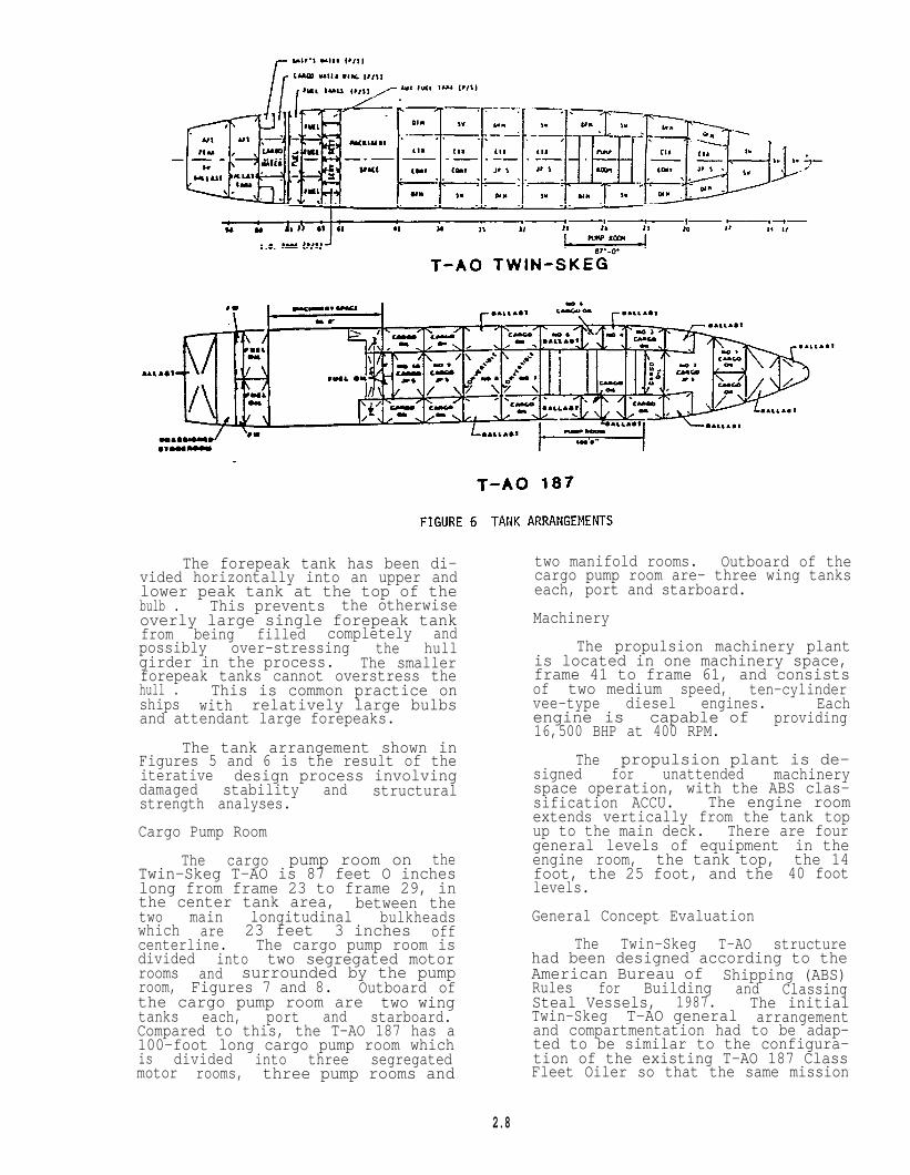
The forepeak tank has been di-vided horizontally into an upper andlower peak tank at the top of thebulb . This prevents the otherwiseoverly large single forepeak tankfrom being filled completely andpossibly over-stressing the hullgirder in the process. The smallerforepeak tanks cannot overstress thehull . This is common practice onships with relatively large bulbsand attendant large forepeaks.
The tank arrangement shown inFigures 5 and 6 is the result of theiterative design process involvingdamaged stability and structuralstrength analyses.
Cargo Pump Room
The cargo pump room on theTwin-Skeg T-AO is 87 feet O incheslong from frame 23 to frame 29, inthe center tank area, between thetwo main longitudinal bulkheadswhich are 23 feet 3 inches offcenterline. The cargo pump room isdivided into two segregated motorrooms and surrounded by the pumproom, Figures 7 and 8. Outboard ofthe cargo pump room are two wingtanks each, port and starboard.Compared to this, the T-AO 187 has a100-foot long cargo pump room whichis divided into three segregatedmotor rooms, three pump rooms and
two manifold rooms. Outboard of thecargo pump room are- three wing tankseach, port and starboard.
Machinery
The propulsion machinery plantis located in one machinery space,frame 41 to frame 61, and consistsof two medium speed, ten-cylindervee-type diesel engines. Eachengine is capable of providing16,500 BHP at 400 RPM.
The propulsion plant is de-signed for unattended machineryspace operation, with the ABS clas-sification ACCU. The engine roomextends vertically from the tank topup to the main deck. There are fourgeneral levels of equipmentengine room, the tank top,foot, the 25 foot, and thelevels.
General Concept Evaluation
in thethe 1440 foot
The Twin-Skeg T-AO structurehad been designed according to theAmerican Bureau of Shipping (ABS)Rules for Building and ClassingSteal Vessels, 1987. The initialTwin-Skeg T-AO general arrangementand compartmentation had to be adap-ted to be similar to the configura-tion of the existing T-AO 187 ClassFleet Oiler so that the same mission
2.8

9
T-AO 187
FIGURE 7
requirements could be achieved.Therefore, the degree of freedom inthe design of the Twin-Skeg T-AOdesign was significantly less than anew design would have been.Extensive concept evaluation, inclu-ding detail weight estimates, longi-tudinal strength, and damaged sta-bility analyses were performed forthe Twin-Skeg T-AO . The finalcompartmentation of the Twin-SkegT-AO evolved after six iterations ofdetail longitudinal strength anddamaged stability analyses.
The overall objective of theTwin-Skeg T-AO was aimed at improvedproducibility with little or no deg-
PUMP ROOM (PLAN)
radation in hydrodynamic perform-ance. The twin-skeg bulbous bow wastherefore designed to offset any ad-verse hydrodynamic effect whichmight be imposed by the produciblehull form. The overall hydrodynamicperformance was found to be betterthan the existing T-AO 187 ClassFleet Oiler (l). Rowever, the twin-skeg did impose some design prob-lems, particularly in the areas ofdamaged stability and longitudinalbending moment. Figures 2 and 9display the sectional area curvesand longitudinal weight distribu-tions of the T-AO 187 and Twin-SkegT-AO . The Twin-Skeg T-AO did pos-sess more buoyancy than the existing .
2-9

T-AO 187 fromHowever, therestricted the
stations 15 to 18. adverse effect caused by the skegsdesign configuration with respect to damaged stabilitydeck house location. was rectified by designinq a shorter
Figure 9 clearly shows that thelongitudinal weight distribution forthe Twin-Skeg T-AO is significantlydifferent from the T-AO 187. Theeffect, in terms of damaged sta-bility for the longitudinal weightdistribution increment, was found tobe far more than the buoyancyincrement from the twin-skeg.twin-skegs were also found to havesome difficulties in counterflooding. The end products of this
machinery space for “ the- Twin-SkegT-A9 .
The tunnel created by the twin-skeg configuration was not conduciveto the development of a functionalmachinery arrangement within thereduced space since the hull is muchshallower in the area of the machi-nery room. At midlength of themachinery space, the Twin-Skeg T-AOtank top is 11 feet above baseline

T-AO 187 VS T-AO TWIN SKEGFIGURE 9 COMPARISON OF LONGITUDINAL WEIGHT DISTRIBUTION
between the skegs and 24 feet abovebaseline from the inboard side ofthe skegs to the ship side. In ad-dition, the ship bottom between theskegs rises rapidly in the aftdirection, dictating the 11 foottank top height. In coinpazison, theT-AO 187 Class has a tank top 6 feethigh. In effect, the T-AO 187 ma-chinery space has one more useablelevel.
The final length of the Twin-Skeg T-AO machinery space was re-duced to 60 feet to obtainsatisfactory results for damagedstability. These machinery arrange-ment sketches were developed withthe primary emphasis on fittingequipment into the space and onlysecondary emphasis on proper adja-cency and access for maintenance.While the equipment was made to fitinto the space available, it is notconsidered a satisfactory machineryarrangement by NAVSEA standards. Ifthis were a completely new design,there would be greater flexibilityto balance the conflicting require-
ments that drove the Twin-Skeg T-AOconfiguration. Therefore, an ade-quate machinery arrangement in alarger compartment could probably bedeveloped, but this would require anadditional analysis.
TWIN-SKEG T-AO PRODUCIBILITY EVALUA-TION
Producibility is systematicplanned production, coordinating,and directing of all manufacturingactivities and influences to ensurehaving goods designed and made inthe most efficient procedure andconfiguration, on time, of adequatequality, and at the lowest practicalcost.
As mentioned earlier, currentU.S. Navy practice, any design forproducibility must consider the pro-curement methods and rules that haveto be followed by law. This ingeneral means that the technicalconfiguration and data in a bidpackage must permit all prospectivebuilders to be able to bid on the
2-11

procurement in a fair and evencompetition. This procedure may notalways permit optimum producibility,which would require the ship to bedesigned to be built by a singleshipyard. Maximum optimization ofproducibility is only possible bydesigning around a given productionsystem/equipment, to the consequen-tial exclusion or handicapping ofothers with slightly different pro-duction systems and equipment. Forthis reason, the T-AO 187 midshipsection drawing was made a ContractGuidance Drawing in lieu of theusual Contract Drawing. This allowsprospective shipbuilders to optimizethe ship structure to suit theirparticular production methodologyand to adjust such details aslongitudinal and web frame spacingfor their individual panel lanecharacteristics. It also permitsthe trade-off of fewer, heavierpiece parts versus additional weldpasses, considering that fillet weldsize is driven by the thickness ofcomponents to be joined.
The next consideration of pro-ducibility is the number of “ shipsto be built to a single design. Theefforts expended on producibilitywill vary to an extent, dependingupon the number of ships to bebuilt.
The Twin-Skeg T-AO is a simpli-fied, integrated and design-to-buildhull with a structure designed forproducibility, with specific detailsof construction. The web framespacing is 14 feet 6 inches versus10 feet O inches on the T-AO 187.This reduces the number of webframes in each compartment betweensubdivision bulkheads from three totwo, but individual components andplating tend to be heavier since thedistance between unsupported platingis larger. In 1986, NAVSEAperformed a design study for theAO 177 Jumboization program whichindicated savings of 44 LT (2.9 per-cent) in Group 1, and 4.1 percent ofGroup 1 labor, by changing from 9feet to 12 feet web frame spacing inthe plug , using standard NAVSEAstructural design practice. Thereis also a smaller number of trans-verse bulkheads, longitudinal stif-feners and frames and floors.Table 2 provides a comparison of thenumber of piece parts required forcertain components on the Twin-SkegT-AO versus the T-AO 187.
The deliberate absence of lon-gitudinal stiffeners in the bilgearea reduces the number of pieceparts but requires the bilge platethickness to be l-1/4 inch, with
appropriate transition strakes 11/16inch thick, inboard and above thebilge plate to the normal 5/8 inchbottom and side shell thickness.The absence of longitudinal in thebilge area also requires two bilgebrackets between each set of webframes, or six bilge brackets perside per compartment of 43 feet 6inches. These bilge brackets arehalf-moon shaped with a flange alongtheir top edge and a flat bar panelstiffener at mid bracket. The endsof this bracket are fitted againstthe longitudinal stiffeners at thetop of and inboard of the bilgeplate. These bilge brackets are de-picted on Figure 4. The work con-tent of these brackets will par-tially offset the gain from thedeletion of the longitudinal stif-feners in the bilge area (as willthe heavier bilge plating).
develop a construction(erection sequence) plan ahead ofthe actual design work is a prudentapproach for the selected shipyardwhen planning a detail ship design.However, considering the Navy pro-curement system, to apply this con-struction plan, it must be designedto suit all prospective buildersequally. This requires access to acurrent data base on shipyard facil-ities, including such information asmaximum crane lift capacity, panellane characteristics, and module orraft transport capabilities.
The original Twin-Skeg T-AOstructural concepts contained avariety of construction detailswhich, while certainly most suitablefor producibility, exceed the amountof detail usually depicted on NAVSEAContract and Contract Guidance draw-ings for T-ships.
The erection sequence plan forthe Twin-Skeg T-AOI indicating unitbreak location, was also provided.The unit breaks indicated were basedon ideally sized modules rather thanconsidering the existing crane capa-cities of a prospective range of
shipbuilders. The crane capacity ofthe eleven U.S. shipyards capableof building Twin-Skeg T-AO sizeships ranges from a low of four 40-LT capacity cranes to a high of one1,200-LT crane over af building way,allowing a range modules forerection from 80/160 to a maximum of1,200 LT.
Because of the attendant prob-lem with the various size modulerequirements, it was decided not toindicate any unit breaks. Butassumed unit break locations wereconsidered in the development of thestructural configurations. Uninter-rupted sequence of erection wasachieved” by assuring that no equip-ment is located across unit breakswhich would prevent the pre-outfitting of modules in question.
Floors and bulkhead plating areinstalled up to a uniform height of10 foot above baseline on the bottomshell. All these vertical platesmounted on the bottom shell are‘capped” with face bars presenting alevel flat surface lower module onwhich to land the upper hull moduleswith relative ease.
Where knuckles occur in theshell or deck plating, they arelocated within a few inches of adeck or longitudinal bulkhead re-spectively. This location allowsease of construction; for example,it permits the slight lengthening ofthe end cut-away of stiffeners orwebs to free the knuckle rather thanperform another radius cut-away overthe knuckle joint. The Twin-SkegT-AO has fewer double curvatureplates because of its simplifiedhull form. Table 2 gives acomparison. Single curvature platesare easier to construct and assemblesince less fitting time is required.
The use of standardized partsof structure for Navy T-ship designswould require the prospective ship-yards to agree on the use of thesame standard structural details andparts. The Twin-Skeg T-AO is de-signed to maximize machine weldingand to avoid, where practicable,structural configurations that wouldrequire manual welding and fit-up.This approach has advantages, butthe details of how to accomplishthis are shipyard specific. Navydesigns must be developed to allowprospective bidders to pursue theirmost efficient methods of produc-tion.
To summarize the producibilityof the design-to-build Twin-Skeg
T-AO in the Navy procurement system,the following comments apply:
1. The design-to-build Twin-Skeg T-AO has distinctadvantages in simplicityof construction, and itsprospective application toa new design T-Ship canresult in substantial costsavings due to the simpli-fied hull shape, and tothe simplified structuralarrangement. Specifical-ly , the Twin-Skeg T-AOstructural concept fea-tures fewer, but heavier,harder to form pieces;minimized bending ofplates and double curva-ture plates; longer framespacing, and componentsserving more than onepurpose, such as floor andfoundation.
2. The design-to-build empha-sis must begin in theFeasibility Study phase,where the designer shouldconsider, based first onthe ship parameters, therange of the prospectivebuilders capabilities, andgeneral producibility,considering the combinedproduction characteristicsof all builders. The pro-ducibility features incor-porated here will have tobe considered every timedesign changes are contem-plated.
3. The emphasis on thedesign-to-build conceptmust continue through Pre-liminary and Contract De-sign. All appropriatesections of the ship spe-cifications should haveproper requirements assur-ing maximum considerationof producibility in theDetail Design process,which is normally per-formed by the builder.
CONCLUSIONS
The results of these studiesindicate certain areas of possibleimprovements, particularly in produ-cibility and hydrodynamics. TheTwin-Skeg T-AO concept presents nounsolvable technical problems, al-though damaged stability is marginal.and machinery space arrangements areunacceptably tight with the currentdesign constraints. If the degreeof commonality with the T-AO 187
2-13

were relaxed, giving the designermore flexibility, the damagedstability characteristics could beimproved. The concept of the pro-ducible, design-to-build ship iscertainly worth further investi-gation for possible application tofuture high-speed naval auxiliarydesigns because of the potential foracquisition and life cycle costsavings.
This evaluation indicates thatthe producibility of future auxil-iary ship designs can be improvedupon by adopting longer framespacings and simplified structuralschemes to reduce the number ofpiece parts, and by minimizing hullcurvature, especially double curva-ture plates. The potential improve-ments, however, would not berealized if these concepts were ap-plied to an existing shipbuildingprogram. These concepts should beconsidered for new auxiliary shipdesigns, where weight sensitivitycan be traded off against produci-bility, and where the design andprogram start-up costs would be ap-plied only once.
RECOMMENDATIONS
Guidelines for the applicationof producibility should be devel-oped, possibly subdivided into threephases -
1 Feasibility Studies
I I Preliminary Design
III Contract Design
The following is an example ofhow producibility guidelines forT-ship design could read. Pleasenote that this is only an examplesince the development of actualguidelines is well beyond the scopeof this paper.
Phase I - Feasibility Studies
o Number of ships planned.
o Approximatetics.
Limitingwater )
- LimitingLawrence
- Limiting
o Approximateship speed
ship characteris-
drafts (air and
beam (PANMAX-St.Seaway)
length
power required(step function
prime mover availabilityrequire larger engine room).
forin
may
o Lea.St curvature hull form com-patible with speed requirementand seakeeping.
o Establish nonexclusive list ofpossible builders and preparegeneral guidelines based onthese builder’s capabilities.
Module size and weight(maximum) for lift, turnand horizontal movement ofmodules.
o Establish data base on build-er’s facilities (most dataexists with MARAD).
Phase II - Preliminary Design
Do not use sheer.
Use straight camber only whererequired for weather deckdrainage.
Establish common panel lanecharacteristics.
Make midship section drawingsContract Guidance and requireshipyards to submit their mid-ship section for approval.
Use flatbar stiffening whereverpractical, if angles are usedvary only the web depth and usesame flange width throughout.
Use as few variations in barstock size as practical.
Design configuration of struc-ture with the fewest possiblepiece parts.
Select the optimum (largest)frame and longitudinal spacingpossible within the compartmen-tation required for stability.
Leave production details, suchcollaring of stiffeners
penetrating bulkheads or otherplated boundaries generallyundefined to permit the indi-vidual builders maximum use oftheir own methodology.
Establish limiting plate thick-nesses for availability and toavoid progressive weight gain(requirement for transitionthickness plates to limit stepsin plate thickness).
Establish common weld passsteps based on plate/stiffenerthickness, which is driven bystiffener/web spacing distance(i.e., plate./stiffener thick-ness at which welding would
2-14

require going from one to twoweld passes).
V-1ine boundaries should beestablished as early as prac-ticable to allow the locationof cable and pipe trunks withinthose boundaries prior tofixing the location of allspaces to be serviced by thesecable or pipe trunks.
Establish minimum number ofdifferent deck height dimen-sions for all levels throughoutthe ship.
Minimize the number of differ-ent size and type closures,scuttles, and accesses throughstandardization. Standardizeroom/space sizes withinarrangement constraints.
Align and locate all Sanitaryspaces to simplify piping.
Generate parameters for com-bined module characteristicsequally suitable to the rangeof candidate builders.
Document the selected para-meters for the design projectat hand and require their useas guidelines throughout thedesign process.
Phase III - Contract Design
For ease of reading we have ar-ranged the recommended generalproducibility guidelines for thisphase by the SWBS category in whichthey most likely fall.
042 - General Administra-tive Requirements
To minimize the number ofdeviations and waivers, thespecification should bewritten in a performance re-quirement format whereverpossible to permit the pros-pective builder a maximumlatitude in the equipmentselection and system config-uration design.
o Contract and Contract Guid-ance drawings should onlydepict the amount of detailsin construction that arerequired to assure satis-factory performance.
070 - General Requirementsfor Design and Construction
o Applicable bridge and canalclearances required shouldbe clearly stated.
Cofferdams and voids shouldonly be used where abso-lutely necessary.
By using a proper overalldesign approach, it isusually possible to colocatespaces of similar contentswhere the adjacency wouldnot require cofferdams.
Structural boundaries shouldserve more than one purposewhenever possible.
071 - Access
The equipment module designneeds to incorporate thespecial access requirementson Navy T-ships. This re-quires tempering the produ-cibility aspect of a systemdesign by considering dam-age control repair accessrequirements.
Access openings should bedesigned so as not to belocated on erection jointswhich would prohibit thepreinstallation of accessclosures in all modules.
072 - Survivability
Survivability requirementswhich, among other things,require the separation ofcrew accommodations are con-trary to producibility but,of course, necessary. Acompromise will have to bemade between separation ofcrew and alignment/adjacencyof similar function spaces.
077 - System Safety
The application of producib-ility guidelines to shipsystems normally has no in-pact on system safety; infact, these producibilityconsiderations enhance sys-tem safety as a byproduct(for example, cable trunksconfine electrical fires andcould be arranged for Halononflooding).
100 - Hull Structure
All guidelines enumeratedunder Phases I and II applyalso to Phase III but willnot be listed again.
Minimize the number of pieceparts.
2-15

Optimize frame and web spac-ing against weight and num-ber of weld passes.
Depth of inner bottom mustconsider module size forlifting/handling
Length of modules to suitsteel availability.
Consider pipe passages andpiping system, flange ormuff pipe joints at erectionjoints.
Consider duct and cable pas-sages in trunks to have-
fewer penetrations.
Consider extent of trans-verse and/or longitudinalframing.
Assure that the rudder sup-port structure is segregatedfrom the aft peak tank, sothat the aft peak tank testdoes not depend on the rud-der being in place.
Align structure with equip-ment foundation requirements(one component - two func-tions).
200 - Propulsion Plant
Prepare a preliminary listof candidate equipment.
Establish functional groupsfor skid/module arrangement.
Consider and select mainte-nance philosophy (change-outor repair in place) beforedetermining connections,pipe joints, bolted platesand flanges.
Use commercially availableequipment without modifica-tion.
Limit Navy type equipment towithin the "fenced areas.”
Standard system modulesshould "be developed for thefollowing:“
- Fuel oil purifiers,pumps, and other compo-nents.
- Lube oil purifiers,pumps, and other equip-ment.
- Fire pumps.
- Air compressors, deny-drators, receivers, andother equipment.
Distillers and freshwater treatment system.
The foregoing. examples ofsystem modules are for illus-tration and not all inclusive.
300 - Electric Plant
Diesel generator set modules
Switchboard modules
Consider adjacency of gener-ator and switchboards(over/under, etc.)
Assure switchboard is inrelatively clean room andnot in the engine roomproper.
Emergency genarator set mod-ule.
Standardizemotor/starter -skid modules toextent possible.
Developbattery/batteryservice modules.
electricpump, etc.,the maximum
standardcharger and
Develop standard M-G setskids & modules.
400 - Command and Surveil-lance
This group consists usuallyof “fencedw systems, and iscomposed of Government Fur-nished Equipment (GFE).
Develop standard T-ship Navycommunications room arrange-ment with a goal of a pre-outfitted space module.
This would permit moreflexibility in schedulingthe work on GFE.
500 - Auxiliary Systems
Standardize pump skids andinstrument boards.
Standardize on the fewestpracticable HVAC modules.
Develop standard refrigera-tion modules.
Modularize auxiliazy boilerand steam system.
2-16

° Standardize hydraulic sys-tems (tank, pump, and con-trols).
600 - Outfit and Furnishings
° Deck houses should have flatsides and square corners.
° Develop arrangement with asmany identical spaces aspossible.
° Develop spaces with standardfurniture arrangement withineach rank group.
° Develop spaces to accepteither whole or half panelsof a commercially availablemarine sheathing.
° Align service (pipe, cableor duct) receiving spacesvertically.
700 - Armament
° Continue implementation ofmodular weapons system in-stallations.
The foregoing, as stated previ-ously, does not pretend to be allinclusive, but rather a guideline topossible areas of producibility ap-plication during the ship design
process as it applies to T-ships.We realize that any one of the itemslisted could be the subject af aseparate paper on producibility. Wehope that this paper might motivatesome thought in the direction offinding procedures to develop moreproducible Navy ship. designs in thefuture.
ACKNOWLEDGEMENTS
We wish to thank VirginiaMonaghan, without whose help thispaper would not have been possible.
REFERENCES
1. Fung, S.; McCallum, D.; Slager,J., and Wilson, J.; ‘Hydrodyna-mic Performance of a Twin-SkegT-AO, "1989 STAR Symposium
2. U.S. Patent No. 4550673, “HullConstruction for Seagoing Ves-sels,” Inventor: SigurdurIngvason, 5 November 1985.
3. Ingvason, S.; McCallum, D. N.and Kraine, G. L.; “An Inte-grated Hull Desiun Performance
‘“ Naval Engi-and Producibility.neers Journal, Vol. 98, No. 3,May 1986.
4. S.I. Shipping Sketches/Vol I.
2-17

Additional copies of this report can be obtained from theNational Shipbuilding Research and Documentation Center:
http://www.nsnet.com/docctr/
Documentation CenterThe University of MichiganTransportation Research InstituteMarine Systems Division2901 Baxter RoadAnn Arbor, MI 48109-2150
Phone: 734-763-2465Fax: 734-763-4862E-mail: [email protected]