the modular virtualized edge for the cable access network
TRANSCRIPT

© CableLabs 2020 1
The Modular, Virtualized Edge for the Cable Access Network
Prepared by Randy Levensalor, Principle Architect / Future Infrastructure Group | [email protected] Carmela Stuart, Director / Future Infrastructure Group | [email protected]
Adrenaline™ Project Future Infrastructure Group
July 2020

The Modular, Virtualized Edge for the Cable Access Network
© CableLabs 2020 2
Executive Summary
Edge computing is a strategic opportunity for cable operators. It is frequently tied to 5G, with the promise of improving performance and
throughput and reducing latency for latency-sensitive or high-bandwidth applications such as augmented reality and virtual reality (AR/VR),
vehicle to everything (V2X), and the Internet of Things (IoT). Opportunities for edge computing, however, are not limited to 5G. It can also
play a prominent role in the fixed cable network, leveraging the thousands of edge locations already established in the cable operator’s
footprint. Edge computing presents an opportunity for cable operators to offer platform and application services to enterprise customers
and consumers, as well as to improve performance in their connectivity services and compete with the 5G narrative of ultra-fast speeds,
ultra-low latency, and massive capacity.
However, edge computing is only one piece of the puzzle. Installing servers in edge locations is not enough to deliver edge services.
Network function virtualization (NFV) and the containerization of applications are necessary to create dynamic network topologies. The
acceleration of virtual network functions (VNFs) and applications through field-programmable gate arrays (FPGAs) and graphics
processing units (GPUs) plays an important role in achieving the latency and throughput requirements of mission critical applications.
Orchestration and infrastructure software lay the foundation to manage a broad ecosystem of VNFs and other edge applications.
Edge computing, orchestration of virtualized applications, and acceleration together enable agile business methods that lead to optimal
use of infrastructure to drive down costs, the ability to offer differentiating services that use edge capabilities, quicker time-to-market for
new network and application features, and more flexibility to scale capacity up or down as required to meet customer needs. This trio of
technologies will be the cornerstone for headend transformation.
Introduction
Depending on the role the cable operator wants to play, the edge cloud may follow different deployment and business models.
Deploying and managing compute at the access edge can be a challenge because of the need to support different deployment models
that meet different operator requirements. Today, operators have many options when choosing where to place network components
within the network (cloud, regional data center, headend, hub, node, etc.), which split configuration to use (Remote MACPHY or
Remote PHY for DOCSIS® DAA, and one of the 8 split options defined by 3GPP for vRAN), and how much of the network stack to
virtualize. In addition, operators that offer both a hybrid fiber-coax (HFC) network and a 4G or 5G mobile network may choose to share
a common infrastructure that supports the convergence of these services.
Multiple-system operators (MSOs) are starting to embrace cloud-native architectures, and most major cable vendors have introduced
virtualized versions of their Converged Cable Access Platforms (vCCAPs). For example, Comcast is rolling out vCCAP solutions with
Harmonic, and WOW! has deployed a virtual Distributed Access Architecture (vDAA) system from Nokia. The forthcoming CableLabs
DAA specifications that support Flexible MAC Architecture (FMA), coupled with the recognition of value that NFV, edge computing, and
Kubernetes can bring to deploying connectivity services, will launch the industry into a new era. In addition, work is currently underway to
enable 5G vRAN (virtual radio access network) over DOCSIS networks, which will expand the number of virtualized applications that
provide connectivity services. The suite of virtualized applications running in an MSO’s edge network may continue to grow over time,
expanding its offerings beyond connectivity. Virtualized revenue-generating applications, such as security services, content delivery
networks (CDNs), and gaming, or virtualized operations applications, such as analytics, telemetry, and DDoS (distributed denial-of-
service) mitigation, could be deployed at any point in the operator’s network. To reduce the complexity, a single platform to manage the
life cycle of communication and edge workloads and to effectively monitor and share infrastructure to reduce costs would be ideal.

The Modular, Virtualized Edge for the Cable Access Network
© CableLabs 2020 3
1 Characteristics of a Successful Virtualized Edge
One of the major benefits of network function virtualization is the ability to dynamically upgrade services with new features or optimizations.
This level of flexibility requires independent management of the services at potentially thousands of locations. For operators deploying
connectivity services at the edge—in a headend, hub, or node, or even a commercial or retail location—having a well-designed
management platform is a necessity. For example, using Remote PHY devices in a new Remote PHY (R-PHY) deployment, a cluster of
Kubernetes managed servers can scale to run many vCCAP cores and thereby handle very large service groups. However, in order for
the platform to scale services up or down to meet latency and throughput demands, it would also need to monitor compute, storage,
and network usage. In addition, the management platform needs to manage the deployment and life cycle of bare-metal installs, virtual
machines, and containers to accommodate operators that have not fully migrated to exclusively container-based solutions. Some
services will also require hardware acceleration through FPGAs or GPUs. The ability to share these resources across more than one
service can bring down the total cost of ownership (TCO) of the infrastructure. Furthermore, because infrastructure hardware may vary
at different locations, a well-designed platform should accommodate the mapping of services to the required resources in a seamless
and consistent manner.
Cost savings can also be made through power and space savings at edge locations. The deployment of vCCAP configurations, for
example, can yield significant costs savings. The Cable and Fixed Broadband Access unit at Intel provided an example of a vCCAP
deployment that showed a reduction in space allocation from an 18-rack unit footprint with an 11.6-kW power requirement (traditional
CMTS, EQAM, and edge router) to a 5-rack unit footprint with a 1.5-kW power requirement when the vCCAP is running on Intel servers.
The freed space and power could be repurposed to run other applications at the edge, either connectivity services to support 5G over a
DOCSIS fronthaul or revenue-generating applications (enterprise services, security services, CDNs, gaming, etc.).
1.1 Location Flexibility
With the adoption of virtualization, the disaggregation of network services to support different use cases and operator requirements is a
trend that is taking hold. We see disaggregation in the traditional HFC network with the development of DOCSIS DAA as well as in the
5G New Radio (NR) domain, where 5G components can have several functional split options. These disaggregated components can
operate at several locations in the network, and service providers have the freedom to decide the ideal location based on performance
requirements, location suitability, and other more dynamic factors such as current load on the network. Examples of different deployment
scenarios and considerations for the placement of disaggregated network components and other applications are discussed in Section 2,
“Deployment Considerations.”
Cable technologies have evolved from a static configuration—a CMTS (cable modem termination system) located at a headend or hub
connected to a pool of cable modems (CMs) built using proprietary hardware—to more modular and dynamic configurations as defined
by DOCSIS DAA. DAA currently allows for two split options: the Remote MACPHY architecture moves both the DOCSIS MAC and PHY
layers out to a Remote MACPHY device (RMD), and the Remote PHY architecture moves only the PHY processing to a Remote PHY
device (RPD). The RMD or RPD is typically placed at the child node. In addition, exploration of using the DOCSIS access network as a
fronthaul for 4G and 5G connections has led to a variety of deployment options based on the choice of where to split the functional
processing of the 4G/5G radio technology stack, giving rise to the split baseband units known as the central unit (CU) and distributed
unit (DU). With this functional split, the CUs, DUs, and radio units (RUs) can be placed at a variety of locations within the cable network.
The network depicted in Figure 1 highlights several possible locations for these components.

The Modular, Virtualized Edge for the Cable Access Network
© CableLabs 2020 4
Figure 1. Example of a Cable Network
Identifying where the “edge” starts in a network is up for debate. Some service providers may consider the start of the edge as the first hop
in the network or even the subscriber’s device or premises. Typically, edge locations can include the headend/hub, node (aggregation
or child), cell site, or subscriber’s premises but not the cloud or regional data center (RDC). Within this paper, the start of the edge is
defined as the cable headend down to the subscriber’s premises (residential, small/medium business, or enterprise).
1.2 Split Configurations
Cable operators are evolving today’s fixed and wireless networks with different network topologies that lower unit costs and improve
end-user performance. New network architectures employ edge strategies in order to scale to device and traffic densities, necessary for
keeping up with subscriber demands. With these new network architectures, however, comes a consideration of facility space, power,
and security, in addition to the goals of reducing latency and providing higher bandwidth and data rates.
Part of this strategy is splitting the network functionality into more modular components, virtualizing some of those network functions,
and then running those virtualized network functions on commodity hardware. Depending on operator requirements, some of the
network processing can be pushed closer to the edge, reaping the benefits that come with more localized processing. Other network
functions can be more centralized and placed farther northbound into the network. The choice is up to the service provider, and
different splitting mechanisms can be employed depending on considerations such as subscriber density at a geographic location
(urban vs. rural), bitrates and latency requirements, power and hardware available at a location, fronthaul capacity, ability to reduce bit-
error rates and improve signal-to-noise ratio (SNR) with shorter radio frequency (RF) paths, and costs of equipment and virtualized
network functions. Figure 2 and Figure 3 show split options for DOCSIS networks and 5G vRAN, respectively.

The Modular, Virtualized Edge for the Cable Access Network
© CableLabs 2020 5
Figure 2. Functional Split Options for DOCSIS Distributed Access Architectures
Figure 3. Functional Split Options for 3GPP 5G New Radio (vRAN)
1.3 Acceleration
Transforming the access network by migrating services from dedicated hardware to software will reduce the TCO and add flexibility,
allowing changes to be made through software updates. This transformation can leverage multipurpose accelerators such as GPUs,
FPGAs, and Smart NICs (network interface cards) to maintain and improve network performance requirements while further reducing TCO.
The popularity and utility of big data analytics and machine learning has been the catalyst driving the demand for higher performance, more
cost-effective computing solutions compared to central processing unit (CPU) solutions, which may not always provide the optimal cost,
power consumption, and scale targeted by other adaptable compute accelerators. For example, Xilinx claims that their Alveo U200 and
U250 FPGA accelerator cards have better performance and efficiency over CPUs or GPUs, by as much as 90% and 50%, respectively,
and a TCO savings of up to 65%. One of the differentiators includes “hardware adaptability,” indicating that the hardware can be configured
according to the needs of the workload being offloaded to the FPGA. Hardware adaptability brings down the TCO because it allows a wide
range of applications to be accelerated by the same hardware. In contrast, CPU and GPU hardware is fixed; only software configurations
are allowed. The claim is that a lesser ability to tailor the accelerator to the workload can limit the overall performance. GPU architecture,
however, is performant on workloads for machine learning training because it excels at massive floating-point computing.
Computational speed is certainly a primary factor to consider when selecting the right accelerator for a given use case, but energy
efficiency is also critical. A significant operational cost is overall power consumption at an edge location. Accelerators that are less
energy efficient will limit the amount of compute that can be added to a location. This factor becomes more critical closer to the subscriber,
where power availability and space are at a premium. Ultimately, achieving the lowest latency, highest throughput, and greatest energy
efficiency for each application executed on the shared infrastructure constituting the next generation of cable access networks is key.
Machine learning and inference are notable applications that benefit from acceleration hardware, but there are many other compute-
intensive functions that can be used in connectivity services for which acceleration makes sense. Application in fast Fourier transform
(FFT), forward error correction (FEC), digital signal processing (DSP), cryptography, MAC scheduling, and time-sensitive packet
processing such as DDoS detection are a few examples of where acceleration hardware can improve performance.

The Modular, Virtualized Edge for the Cable Access Network
© CableLabs 2020 6
The Adrenaline project at CableLabs is focused on managing a heterogenous set of accelerators available at different locations in the
cable access network and mapping applications with specific compute requirements to those resources. The goal of the Adrenaline
project is to promote technologies and architectures that transform the network into a distributed heterogeneous computing platform
with dynamic workload allocation. More about the Adrenaline project can be found at https://openadrenaline.com/.
Within ETSI, the Multi-access Edge Computing (MEC) initiative’s Industry Specification Group (ISG) has done extensive work with edge
deployments, especially 5G deployments. At a high level, the Adrenaline project is compatible with the MEC architecture. It leans
towards the adoption of existing de facto and de jour standards, leveraging Kubernetes open-source APIs in particular.
2 Deployment Considerations
Several categories of services can be virtualized: connectivity services (vCCAP, v5G Core, etc.), operational services (analytics,
telemetry, etc.), over-the-top (OTT) applications (gaming, CDN, etc.), and other general network services (DNS, DHCP, SDN Control,
etc.). The placement of these virtualized services within a network can vary among service providers and regions. Later sections discuss
possible deployment scenarios that can take advantage of edge infrastructure, including a DOCSIS DAA deployment, a 5G mobile
deployment, and a converged deployment in which HFC and 5G components may be co-located in the service provider’s network.
2.1 Network Locations
Network location characteristics will vary considerably. Physical security, power profiles, rack space, compute capability, entity
managing the location (service provider vs. third-party cloud provider), latency and throughput capability, and distance from subscriber
are all factors to consider when deciding where in the network to place virtualized services. Locations are summarized in Table 1.
TABLE 1. SUMMARY OF NETWORK LOCATIONS
LOCATION CONSIDERATIONS EDGE OR CORE?
Cloud Unlimited power and space; Managed by third-party cloud provider; Can run cloud workloads across multiple regions for high availability/fault tolerance; Can enlist multi-cloud providers when needed
Core
RDC Climate controlled; Managed by service provider; ~750 kW–1 MW power Core
Headend/Hub Climate controlled; Managed by service provider; ~300 kW–700 kW power Edge
Aggregation Node Requires environmentally hardened equipment; ~200 Watts power Edge
Child Node Requires environmentally hardened equipment; ~200 Watts power Edge
Customer Premises
Residential, SMB, enterprise; Climate control and power vary by customer type; SMB/enterprise may need sustained operations for mission-critical applications when disconnected from external networks
Edge
Cell Site Like customer premises, climate controlled and power can vary greatly based upon location Edge
2.1.1 Cloud
The cloud is the most flexible and typically least expensive option for hosting compute services. The network location and capabilities of
the cloud are diverse, but higher and more varied network latency, network throughput, and service interruptions prevent the cloud from
being ideal for many access network components and edge use cases. The cloud can be hosted by the service provider or provided by
a third party. The three largest hyperscale cloud providers are Amazon Web Services (AWS), Google Cloud, and Microsoft Azure.1
A cloud is a set of services provided through a programable network interface. It can provide bare metal servers, where the service can
run the Adrenaline project or provide Kubernetes as a service. For this paper, a cloud is considered a centralized location that is not
required to be in the service provider’s network.
1 According to S&P Global (login required).

The Modular, Virtualized Edge for the Cable Access Network
© CableLabs 2020 7
For high availability, it is always recommended to run cloud workloads across multiple regions to provide a greater level of fault tolerance.
Ideally, cloud workloads would be able to fail over two or more cloud providers in geographically distinct regions. However, multi-cloud
applications are not always cost effective and do not take full advantage of the differentiated services offered by each cloud provider.
2.1.2 Regional Data Center (RDC)
RDCs are medium to large data centers geographically distributed across a service provider’s network. Smaller operations may have
only one RDC, whereas larger operators have 10 or more throughout their footprints. RDCs do not provide consistent low-latency
performance to all customers because they are not distributed consistently throughout the network. An RDC can be used to house
central management software to run the infrastructure in the core network, as well as some analytics and other applications where it
can provide bandwidth savings.
2.1.3 Headend/Hub
The edge begins at the headend and hubs (which are treated equally in this paper). Much of the focus on edge applications for cable
operators is at the headend. Moving from a traditional CCAP appliance to DAA and a virtual CMTS has resulted in a reduction in space
from 20 rack units to 1 rack unit for at least one cable operator. This additional space can be used to improve network efficiency or
deploy additional revenue-generating applications.
Cable modems have traditionally terminated at the headend and hubs, and cable operators frequently have multiple classes of
headends and hubs throughout their network. They are climate-controlled buildings with power and space for several racks. They can
vary in size, but many headends will have about 18–20 rack units of space.
2.1.4 Aggregation Node
An aggregation node is a smaller location with minimal power, typically less than 200 W, that is exposed to the elements. Traditionally,
these sites were limited to wavelength-division multiplexing (WDM) for optical networks that feed optical nodes for HFC plants, cell
sites, and passive optical networks (PONs). With FMA and other disaggregation technologies like remote optical line terminals (rOLTs),
higher level capabilities can be deployed in these nodes utilizing low-power computing and accelerators.
2.1.5 Child Node
Like an aggregation node, a child node typically has less than 200 W of power and no environmental controls. These sites have
typically been fiber nodes in the cable network. Components deployed in a child node will fan out to connect to multiple customers with
some amplification to extend the range of the signal.
2.1.6 Residential and Small/Medium Business (SMB) Customer Premises
Residential and SMB customers have very similar needs. The compute available at these locations it typically limited by the gateway
device, but the rapid growth of IoT devices and streaming media has created opportunities for these devices to provide additional
services. Extending the compute capabilities on these devices will enable additional services and maintenance features.
2.1.7 Enterprise Customer Premises
Large enterprise customers require a comprehensive network solution. Typically, these customers have stacks of purpose-built equipment,
but it can now be replaced by a small cluster of servers. Existing services can be consolidated onto general purpose servers, and
additional services can also be provisioned. These clusters can be small, managed by controllers at the headend, or standalone, with
an independent management stack and the ability to perform critical management tasks if disconnected from external networks.

The Modular, Virtualized Edge for the Cable Access Network
© CableLabs 2020 8
2.1.8 Cell Site
Cell sites (towers) are either owned and operated by the cable operator or owned by a third party with the cable operator providing a
backhaul for the site. In either case, there are opportunities to deploy edge computing resources at cell sites. Location size and
available power will vary greatly from site to site.
3 Network and Operational Services
Several network and operational services can be deployed at various locations within the network. Some services will be deployed in
only one location, whereas others are deployed across multiple locations.
3.1 Edge Infrastructure Management
The applications listed in Table 2 are examples of the components needed to run an edge platform.
TABLE 2. EDGE INFRASTRUCTURE MANAGEMENT APPLICATIONS
SERVICE PURPOSE CONSIDERATIONS LOCATION(S ) DEPLOYED AT MULTIPLE LOCATIONS?
Adrenaline Project
Provides standard interfaces to manage computing and acceleration resources at the edge
Defined as an edge computing platform, but can run north of the provider edge to maintain a common management platform across the service provider’s infrastructure
Cloud, RDC, headend, node (agg., child), premises, cell site
Yes
Adrenaline Edge Controller
Manages Adrenaline project in the nodes and smaller customer locations
Reduces resource requirements on nodes by centralizing control in the headend; Can be placed in customer premises for a standalone site
Headend No
3.2 Service Life Cycle Management
Service life cycle management components (Table 3) control the services, including their creation and deletion. They also monitor and
repair running services.
TABLE 3. SERVICE LIFE CYCLE MANAGEMENT COMPONENTS
SERVICE PURPOSE CONSIDERATIONS LOCATION(S ) DEPLOYED AT MULTIPLE LOCATIONS?
Service Assurance Platform (SAP)
Collects data from a wide variety of sources, validates that they meet service level agreements (SLAs), and performs remediation actions if the SLA is no longer being met
May have dependencies on analytics engines for pre-processing data, as well as on physical and virtual components
Cloud, RDC, headend
Yes
Analytics Delivers insights into network or application performance
When located throughout the network, allows for data to be aggregated and analyzed closer to the source and for scaling at the edge; As a common analytics platform, can provide access to telemetry and monitoring data and support a consistent security model.
Cloud, RDC, headend, premises
Yes
Service Orchestration
Deploys services across an entire network
Main command and control center for network configuration and deployment of services
Cloud No

The Modular, Virtualized Edge for the Cable Access Network
© CableLabs 2020 9
3.3 Shared Network Services
Common network services can be leveraged by both the infrastructure and other services. As interoperability increases over time,
additional opportunities to leverage best-in-class components will arise. Shared network services interoperate with both physical and
virtual components across the network. Table 4 lists a representative set of such services; individual deployments will vary.
TABLE 4. EXAMPLES OF SHARED NETWORK SERVI CES
SERVICE PURPOSE CONSIDERATIONS LOCATION(S ) DEPLOYED AT MULTIPLE LOCATIONS?
Software-defined networking (SDN) controller
Manages the fabric at a location and the overlay networking between components at a single location
When placed within the failure domain it is managing, reduces additional points of failure; Global SDN controller also deployed centrally to manage interconnects between sites
Cloud, RDC, headend, premises
Yes
DNS Domain Name System; Managed globally and often needs to be accessed outside of the network
Proxies/local servers may be deployed throughout the network; primary DNS service is typically centralized
Cloud No
DHCP Provides IP addresses for components in the service provider’s network
Proxies/domain-specific servers can be deployed throughout the network; Can be located and managed centrally for multiple services (DHCP not bandwidth or latency specific)
RDC No
vBNG Virtual Broadband Network Gateway router
When deployed at the edge with a mobile core and/or vCCAP, removes need for local traffic between customers served off the same headend to be backhauled to the core network; Also allows customers to access other services hosted in the headend
RDC, headend No
Virtual router (vRouter)
Lightweight; Provides basic routing between components at the edge
Does not need to implement all of the same capabilities as a vBNG
Node (agg., child), premises, cell site
No
PTP Master Provides a source for RFC 8173 timing Has very precise timing requirements Headend No
3.4 Common Security Services
Network security (see Table 5) is always critical for cable operators. Security needs to be applied at each location in the edge. It is
important to consider micro-segmentation (services are protected from each other), physical security, and user management.
TABLE 5. COMMON SECURITY SERVICES
SERVICE PURPOSE CONSIDERATIONS LOCATION(S ) DEPLOYED AT MULTIPLE LOCATIONS?
Infrastructure Security
Firewalls, intrusion detection systems (IDS), intrusion prevention systems (IPS)
Catching a security breach closer to the edge will minimize impact to the network and other users.
Everywhere Yes
Transparent Security
Source-based DDoS mitigation solution Programable switches with compute and acceleration applications are used to identify an attack’s source device and mitigate the attack before it leaves the network. With BNGs distributed at the headend, a DDoS solution like this needs to protect customers from geographically local attacks.2
Headend, premises No
2 See https://github.com/cablelabs/transparent-security for additional information.

The Modular, Virtualized Edge for the Cable Access Network
© CableLabs 2020 10
4 DOCSIS Deployment Scenario
With DOCSIS DAA (Figure 4), DOCSIS components can be deployed at different locations in the network. This section describes the options for deploying them.
Figure 4. DOCSIS DAA Deployment 4.1 RPD
The RPD can be deployed across any edge location. Current offerings for RPDs are largely based on a small management CPU and ASICs or FPGAs. A common solution is to deploy the RPD in child nodes, which supports a fiber-deep deployment in the network.
4.2 vCMTS
The vCMTS is on the data plane for all DOCSIS IP traffic and must be on the core side of the RPD and the customer side of the Broadband Network Gateway (BNG). It will typically be deployed in a headend, where it can be co-located with other edge applications. When compute is available in the aggregate node and RPDs are deployed in child nodes, one vCMTS can manage several child nodes. Latency and maximum utilization improve when there is a large distance between the aggregation node and the headend or hub because the grant time for upstream data transmission windows is reduced.
4.3 Video Core
The video core delivers the QAM-based video traffic. It needs to be located where the video feeds are aggregated, typically in the headend. With FMA, one video core may serve many RPDs, and some cost is saved by centralizing the video core and processing. The video being aggregated must be transcoded to multiple formats before it is delivered to the video core, and the video must be pre-formatted and/or transcoded for distribution to the set-top box (STB). GPUs are typically used to accelerate this transcoding and pre-

The Modular, Virtualized Edge for the Cable Access Network
© CableLabs 2020 11
formatting. A benefit to running a software-based video core is the flexibility to adapt to changing video distribution technologies. For more information, the NCTA has published a paper on delivering QAM video over DAA.3
4.4 PacketCable Aggregator and DOCSIS Control Plane Applications
The PacketCable Aggregator and DOCSIS Control Plane components can be run centrally, freeing up resources at the edge. Additionally, the PacketCable Aggregator, PacketCable Multimedia (PCMM) Policy Server, MAC Manager, and TFTP server (required to keep provisioned services running) can be in the RDC, reducing the likelihood of service interruptions seen with external connectivity and cloud providers.
4.5 Service Orchestrator
Service orchestration, billing, and other business intelligence components are well suited to run in the cloud because use of these applications can vary greatly over time. Brief interruptions to these services should not affect provisioned services.
5 Mobile Deployment Scenario
This section focuses on the 5G mobile core (Figure 5). Similar deployments can be achieved with 4G and Control and User Plane Separation (CUPS). See also two white papers published by ETSI on 5G edge deployment options and 4G-to-5G deployments.4
Figure 5. Mobile Deployment
3 “Delivering QAM Video in Distributed Access Architectures,” C. Howlett, D. Johnson, K. Meisen, SCTE-IBSE CableTec Expo 2019 & 2019 Fall Technical Forum, September 30–October 3, New Orleans, LA 4 “MEC in 5G Networks,” June 2018, ETSI White Paper 28, “MEC Deployments in 4G and Evolution Towards 5G,” February 2018, ETSI White Paper 24

The Modular, Virtualized Edge for the Cable Access Network
© CableLabs 2020 12
5.1 Central Mobile Core
The central mobile core has management and control plane functionality that is global to the mobile deployment and can be deployed
centrally in a cloud environment. It includes the following components.
• UDM, UDR, AUSF—Unified Data Management, User Data Repository, Authentication Service Function; like the 4G HSS
(Home Subscriber Server)
• PCF—Policy Control Function; like the 4G PCRF (Policy and Charging Rules Function)
• SMSF—SMS Function; like the 4G SMS-SC (SMS Service Center)
• NEF—Network Exposure Function; like the 4G SCEF (Service Capability Exposure Function)
• NRF—Network Repository Function
• NSSF—Network Slice Selection Function
• UDSF—Unstructured Data Storage Function
5.2 Access and Mobility Management Function (AMF) and Session Management Function (SMF)
The AMF and SMF are the two mobility management functions and are placed in the same region to meet latency needs. They are
similar to the 4G MME (Mobility Management Entity).
5.3 User Plane Function (UPF)
The UPF allows traffic to connect from the mobile network to the data network. With an edge deployment of the UPF, additional
services can be accessed at the point of the UPF. It is similar to the 4G P-GW, S-GW, and L-GW (PDN, Serving, and Local Gateways).
5.4 Control Unit (CU), Distributed Unit (DU), and Radio Unit (RU)
The CU and DU can be placed at several points across the access network, anywhere from the headend to the customer premises.
Both components are in the same location with an option 2 split and an option 7.2 split. The timing and latency requirements make
these components excellent candidates for deployment using FPGA-based acceleration.
With an option 7.2 split, the CU/DU can be deployed in a node or headend. This deployment allows less expensive and lower power
radios to be deployed in the field; it also allows the CU/DU, which can run on shared computing resources, to be centralized.
Co-located deployment of the RU and CU/DU at an edge site with the UPF enables the use of the less expensive RU while leveraging
edge computing resources for the UPF, CU/DU, and other edge applications.
6 Edge Services
Placing high-bandwidth and low-latency OTT applications like CDN, security video processing, and gaming at the edge of the network
benefits both the subscriber and the operator. Proximity to the subscriber reduces the amount of traffic flowing northbound into the
network, which increases overall metro and core network capacity and reduces the chances of congestion for other applications. It also
reduces latency for the subscriber, resulting in a better quality of experience. Edge services like these applications (see Table 6) can be
co-located with connectivity services. Applying the same management approach and infrastructure to both types of services by using
the Adrenaline project and Kubernetes to host them brings down the TCO and enables field trials of new services to be launched in
days rather than months without costly modifications or hardware replacement.

The Modular, Virtualized Edge for the Cable Access Network
© CableLabs 2020 13
TABLE 6. EDGE SERVICES
SERVICE DESCRIPT ION CONSIDERATIONS LOCATION
Content Delivery Network (CDN)
Tiered CDN providing local access to content
Content can be pushed to locations where it is needed; Eliminates the need to use DOCSIS network when there is repeated access to the content at the same site
Cloud to customer premises
Security video processing
Analyzes, compresses, and backs up security video
Uses edge storage and computing, including GPUs; Footage can be analyzed locally; Compressed and encrypted copies can be sent to the cloud for backup
Cloud and customer premises
Software-defined wide area network (SD-WAN)
Allows users to securely connect to applications over multiple networks
Provides secure access to applications hosted on the customer premises and in the cloud for both local and remote users
Cloud and customer premises
Firewall Provides additional security and enforcement
Customer can personalize on-premises virtual firewall to meet business needs; Special-purpose hardware no longer needed
Customer premises
Intrusion detection system (IDS)
Detects unauthorized activity on the network
Can be deployed and managed by service provider; Updates and configuration are taken care of for the customer
Customer premises
Edge gaming Hosted gaming platform Paired with low-latency DOCSIS tech to meet latency requirements Headend
6.1 Securing Edge Services with Dual-Stack Isolation
Applying cloud-native concepts at the cable operator edge raises the concern for security, both physical and logical. In the traditional cable plant, much of the hardware and applications are located behind a secured facility. The concept of “shared infrastructure” does not apply because the components are purpose-built on proprietary hardware. Virtual applications that run closer to the subscriber may be in a cable node or even on the premises and may be physically less secure than an application running at a headend or hub. The platform managing the deployments of these applications must ensure that rogue applications are not installed at an edge location and that an application with an existing flaw does not impede other applications on the same infrastructure, especially if an operator is co-locating their connectivity services applications in addition to OTT applications (gaming, CDNs, etc.). In a “dual-stack” configuration, the logical or physical separation of connectivity services from OTT applications is paramount. A dual-stack deployment, shown in Figure 6, isolates and prioritizes mission-critical connectivity services while supporting OTT workloads on the same underlying infrastructure.
Figure 6. Dual-Stack Deployment of Connectivity Services and OTT Applications
The Modular, Virtualized Edge for the Cable Access Network
© CableLabs 2020 14
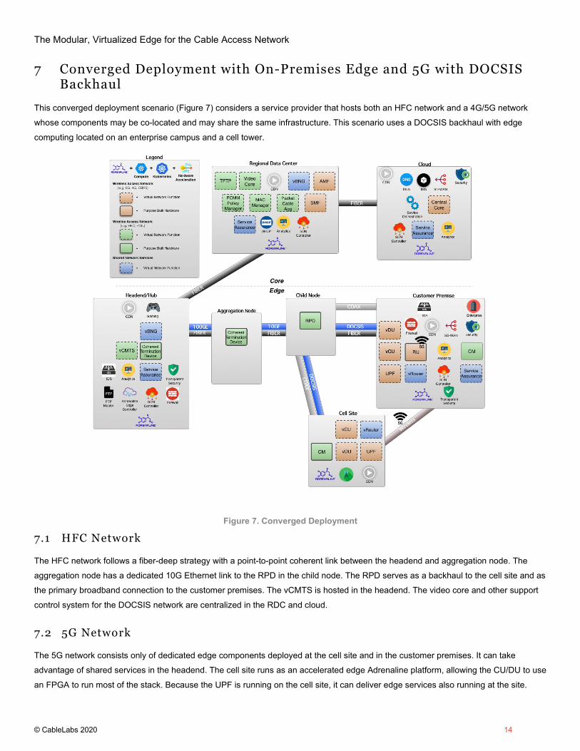
7 Converged Deployment with On-Premises Edge and 5G with DOCSIS Backhaul
This converged deployment scenario (Figure 7) considers a service provider that hosts both an HFC network and a 4G/5G network
whose components may be co-located and may share the same infrastructure. This scenario uses a DOCSIS backhaul with edge
computing located on an enterprise campus and a cell tower.
Figure 7. Converged Deployment
7.1 HFC Network
The HFC network follows a fiber-deep strategy with a point-to-point coherent link between the headend and aggregation node. The
aggregation node has a dedicated 10G Ethernet link to the RPD in the child node. The RPD serves as a backhaul to the cell site and as
the primary broadband connection to the customer premises. The vCMTS is hosted in the headend. The video core and other support
control system for the DOCSIS network are centralized in the RDC and cloud.
7.2 5G Network
The 5G network consists only of dedicated edge components deployed at the cell site and in the customer premises. It can take
advantage of shared services in the headend. The cell site runs as an accelerated edge Adrenaline platform, allowing the CU/DU to use
an FPGA to run most of the stack. Because the UPF is running on the cell site, it can deliver edge services also running at the site.

The Modular, Virtualized Edge for the Cable Access Network
© CableLabs 2020 15
7.3 Edge Services
Users will be able to access the local edge resources at the customer premises and the cell site without needing to traverse the node or
the DOCSIS network. Services in the headend, such as cloud gaming, are accessible without having to return to the core network.
Conclusion
Synthesizing an approach to transform the cable access network that incorporates edge computing, orchestration of virtualized
applications, and acceleration will result in significant cost savings. It will reduce power consumption, space, and hardware costs and
support the flexibility needed to create customized network topologies that improve throughput and reduce latency for subscribers.
Decoupling the network software from proprietary hardware increases the cadence of upgrades to a system, which reduces the time to
market for new capabilities and optimizations. Cable operators can also more easily explore offerings of new services that use the
same infrastructure and management capabilities that support their connectivity services. Embracing these technologies in unison to
form a self-optimizing, highly automated, dynamically scalable network opens the door to new innovations and creates a viable path
forward to compete against other network providers.
Disclaimer This document is furnished on an "AS IS" basis and CableLabs does not provide any representation or warranty, express or implied, regarding the accuracy, completeness, noninfringement, or fitness for a particular purpose of this document, or any document referenced herein. Any use or reliance on the information or opinion in this document is at the risk of the user, and CableLabs shall not be liable for any damage or injury incurred by any person arising out of the completeness, accuracy, infringement, or utility of any information or opinion contained in the document. CableLabs reserves the right to revise this document for any reason including, but not limited to, changes in laws, regulations, or standards promulgated by various entities, technology advances, or changes in equipment design, manufacturing techniques, or operating procedures. This document may contain references to other documents not owned or controlled by CableLabs. Use and understanding of this document may require access to such other documents. Designing, manufacturing, distributing, using, selling, or servicing products, or providing services, based on this document may require intellectual property licenses from third parties for technology referenced in this document. To the extent this document contains or refers to documents of third parties, you agree to abide by the terms of any licenses associated with such third-party documents, including open source licenses, if any. This document is not to be construed to suggest that any company modify or change any of its products or procedures. This document is not to be construed as an endorsement of any product or company or as the adoption or promulgation of any guidelines, standards, or recommendations.