the laws of re ection and refractionzhaoy/reflection.pdf · the laws of re ection and refraction...
TRANSCRIPT
The Laws of Reflection and Refraction
Alec Cook and Ryan PappafotisDepartment of Physics and Astronomy,
University of Georgia, Athens, Georgia 30602
(Dated: 8 December 2015)
Among the most elementary laws of optics are those concerned with reflection and refraction.In this laboratory experiment, we attempt to verify the validity of two of these laws: the law ofreflection and Snell’s law. Furthermore, we employed these laws in order to experimentally measurethe index of refraction of a glass prism. Throughout the experiment, we utilized LEGO bricks andthe camera on a smart phone as cost-efficient laboratory devices.
I. INTRODUCTION
The field of optics has a wide range of applications inmodern technology, and virtually all of these applicationsare dependent on the validity of the laws of reflection andrefraction. These physical laws form the basis of modernoptics, and many of the more complex optical theoriesare built on the foundation provided by these laws. Thegoal of this project is to use a smart phone and LEGObricks as accessible, convenient laboratory equipment todemonstrate the laws of reflection and refraction, therebyproving that the basis for many other optical principlesholds true.
Reflection and refraction are concerned with how lightacts as it encounters a boundary between two differentmedia. The human eye utilizes reflection to allow forsight, and therefore reflection is fundamental to all op-tical experiments. The first formulation of the law ofreflection can be found in Euclid’s Elements, circa 300BCE, and has been essential for countless studies of ge-ometrical optics ever since [1].
Refraction occurs when light changes its path as it en-ters a new medium with a different index of refraction [2].The behavior of light as it refracts at the boundary canbe described by Snell's law, Equation (2). WillebrordSnellius was credited with formulating this relationshipin the seventeenth century [3]. Refraction is the primaryprinciple utilized by lenses, which are used in numerousoptical devices, making refraction essential to the studyof optics.
The basics of geometrical optics are often overlookedbecause they have become quite trivial in the academicworld. However, as previously stated, the geometricallaws of optics are essential to understanding most opticalphenomena. For this reason, the purpose of the followingexperiment is to take a step back and study these laws,which are the basis for so much else.
II. RELEVANT PHYSICS
The optical effects we explore in this experiment definethe behavior of light as it passes through one medium andencounters another. As an electromagnetic wave, light
propagates as a cyclical disturbance in the electric andmagnetic fields and does not require a medium in whichto travel. When light does encounter matter, it is scat-tered by interaction with the atoms that make up the ma-terial. This scattering occurs in all directions; however,assuming the medium is uniform and relatively dense, thescattering is canceled out in all but the forward direction[4]. Therefore, the direction of the propagation of a waveof light is not affected so long as it remains in a uniformmedium. This is known as the law of transmission [5].
A. Reflection
We are primarily interested in the behavior of lightas it encounters a novel medium. When this occurs, aportion of the incident wave is reflected at the boundary,another is transmitted into the new medium, and the restis absorbed by the matter the light encounters. Here, wewill discuss a specific type of reflection known as specularreflection, in which the incident light is perpendicular toa flat, reflective surface and the incident light, reflectedlight, and normal to that surface are all contained in asingle plane. This is referred to as the plane-of-incidence.The familiar reflection effect we experience when lookinginto a mirror is specular [4].
This type of reflection is defined by an astoundinglysimple law, known as the law of reflection. When light isincident on a surface at an angle θ1 to the surface normal,the beam will be reflected an an equivalent angle θ2 inthe opposite direction [4].
θ1 = θ2 (1)
This flipping of incident light rays maintains their wave-lengths but inverts their order with respect to one an-other. This is the source of the mirror image we observe,which is inverted in one direction.
B. Refraction
The portion of the incident wave which is not reflectedbut instead continues into the second medium experi-ences a phenomenon known as refraction. The two media
2
interact with the light differently and impede its passageat different rates. Every medium has an optical propertyknown as the index of refraction, n, which is defined asthe ratio between the speed of light in a vacuum, c, andthe speed of light in that medium. This change in speedat the interface causes the beam to bend, changing itsdirection. According to Snell’s law, also known as thelaw of refraction [4],
n1sin(θ1) = n2sin(θ2). (2)
Here, θ1 and θ2 denote the incident and refracted anglesas measured from the normal, while 1 and n2 are the in-dicies of refraction in the respecitive media. When theincident light is perpendicular to the interface, there is norefraction. However, as the incident angle increases, sodoes the effect of refraction. As a result, when a beam oflight travels from one medium to another with a lower in-dex of refraction, an incident angle above a certain pointwill cause the beam to refract so much that it is unableto leave the original medium and reflects across the bar-rier instead. This phenomenon is known as total internalreflection [4] and occurs whenever the incident angle isgreater than a critical angle given by
θcritical = arcsin(n2n1
). (3)
III. MATERIALS
This experiment was designed to be carried out usingmaterials that the average person could easily acquire, asan exercise in proving the accessibility of optical experi-mentation. As such, we conducted this experiment with a$50 budget. The materials we utilized in this experimentwere as follows:
• The camera on a Samsung Galaxy S6 smart phone,already owned by a member of the team
• An office laser pointer, in the possession of anotherteam member
• A semicircular glass prism
• A small, silvered mirror
• A biconvex optical lens with focal length 50 mm
• A biconvex optical lens with focal length 200 mm
• A series of LEGO bricks, provided by the instructor
• Several assorted textbooks
• Various clamps and mounts
• Paper printed with angular measurements
The only items on this list we needed to purchase werethe lenses and the glass prism, which cost us $24.10; therest were all easily available to us.
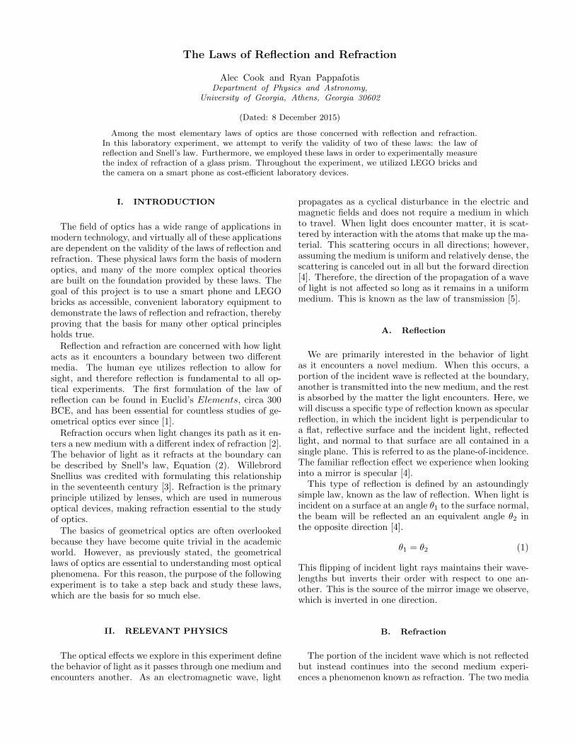
FIG. 1: Our experiment apparatus, shown here including thelaser, beam expander, angle grid, mirror, and smart phonecamera.
IV. EXPERIMENTAL SETUP
Here, we describe the process by which we preparedour experiment and the methods we used to collect ourdata.
A. Testing the Law of Reflection
Both of our experiments depended upon analyzing thepath that a beam of light takes as it is incident on theboundary between two optical media. As such, it was im-perative that we were able to view the laser beam before,during, and after its interaction with that boundary. Toachieve this, we angled a laser beam slightly downwardagainst a flat sheet of white paper. The beam makes astreak against the paper, which is highly reflective andmakes the streak clearly visible. However, the length ofthe streak is limited by the beam waist. Therefore, weconstructed a beam expander to increase that waist andsimilarly lengthen the visible path of the laser. Our beamexpander consisted of two biconvex lenses, having focallengths of 50 and 200 millimeters. We placed them 250millimeters apart to magnify our beam by a factor of four.We constructed our beam expander using LEGO blocks,creating an effective and highly modifiable apparatus ata low cost. The expander held the lenses upright and atthe correct distance.
We used a laboratory clamp to hold the laser at thecorrect height, and we stacked a series of books to raisethe white paper to that same height. We printed a semi-circle marked with a series of angle measurements on thepaper to make data collection easier. Then, we calibratedthe apparatus. We adjusted the level of light in the roomso that both the laser and the angle markings were clearlyvisible on the paper. Then, we directed the laser throughthe beam expander and angled it so that it produced thelongest possible streak on the paper. A small, silveredmirror was then placed in the center of the semicircle

3
FIG. 2: A measurement taken with the silvered mirror, dis-playing an incident beam (right) and the reflected beam (left).
at the edge of the page. A second semicircle page wasplaced under the first to allow for accurate measurementsof angles as the incident angle of the mirror was changed.Beginning with the mirror perpendicular to the beam,the mirror and top semicircle page were rotated at incre-ments of 5◦, up to 40◦. At every new location, a smartphone was used to take a picture of the beam pattern onthe page, which showed the incident and reflected angles.We later processed this data by extending the beam linesto the edges of the angle grid, as per the law of transmis-sion, to allow for exact measurements. This process wasrepeated three times to create error bars for our mea-surements.
B. Testing Snell’s Law
We used the same apparatus to test the validity ofSnell’s law. We removed the mirror and replaced thesemicircular angle measure with a full circle. Then, weplaced a semicircular glass prism so that the midpointof the flat side of the prism aligned with the center ofthe circle. The prism is designed so that light directedtowards this point will be perpendicular to any point onthe round side of the prism, preventing refraction fromoccurring. The path of the beam is only altered by thesecond, flat interface, simplifying our measurements. Wepassed the beam through the prism at 11 different in-cident angles, in intervals of 4◦ from 0◦ to 40◦. Higherincident angles than this began to exhibit signs of totalinternal reflection, preventing us from accurately collect-ing data. We recorded the refracted angle at each ori-entation and repeated the entire process three times inorder to put error bars on our data.
V. DATA AND ANALYSIS
Here, we discuss the data we collected and the methodsby which we analyzed that data.
FIG. 3: A refraction measurement, here with the angle ofincidence set to 32◦.
FIG. 4: The data collected in our reflection experiment, witherror bars fitted to the points.
A. Reflection
The data collected for the reflection portion of the ex-periment, including error bars, is displayed in FIG. 4. Asexpected from Equation (1), the data appears to have alinear correlation. To test this, the data was fitted toa model described by Equation (1). The best fit lineis plotted along with the data in FIG. 5. The best fitline for this linear model has 8 degrees of freedom and a
FIG. 5: A fit of the data in FIG. 4 in the form of Equation(1).

4
FIG. 6: Residuals of the data points plotted in FIG. 4.
FIG. 7: The data collected in our refraction experiment, witherror bars fitted to the points. The sine of the angles is plottedhere, to better show the linear nature of Snell’s law.
chi-squared value of 0.00006, giving a p-value of approx-imately 1. To obtain an even better idea of how well thecurve fits the data, we can study the residuals plotted inFIG. 6. As shown, the residuals are centered around 0,have very small values, and are randomly distributed overthe interval, suggesting that they are reasonably preciseand do not introduce a significant bias into our system. Ifwe assume the validity of the law of reflection, it is verylikely that we would collect data similar to the resultsthat we were able to draw in our experiment.
Having confirmed the linear relationship between theincident and reflected angles, we would also like to verifythat there is no scalar factor in the relationship betweenthe two. From Equation (1), it can be seen that whenthe reflected angle of the laser is plotted against the in-cident angle, the slope of the data should be equal to 1.When fitting our data with the linear model, a slope of0.971 +/- 0.007 was calculated. This yields an error of2.9%, which we believe to be well within reasonable errorbounds.
FIG. 8: A fit of the data in FIG. 7 in the form of Equation(2).
FIG. 9: Residuals of the data points plotted in FIG. 7. Theytake a sinusoidal shape because we graphed the sine of theraw data values.
B. Refraction
Our refraction data also seemed to uphold the theoreti-cal model. We collected the incident and refracted anglesfrom our experiment and created error bars. Then, wetook the sine of each of those angles and attempted to fitthem to a linear model, as in Equation (2). The residualstake a sinusoidal shape because of this alteration. Theresultant fit seems to follow the data very closely. Thisis supported by statistical analysis; the fit has 10 degreesof freedom and a reduced chi-squared value of 0.00018,suggesting that this data is well in line with what Snell’slaw would lead us to expect. The error bars on the datapoints are small, suggesting that our data is precise aswell. The fitting algorithm suggested that the index ofrefraction of our prism was 1.51 +/- 0.01; this yieldsonly 0.59% error when compared to the accepted valueof 1.517. Furthermore, this index of refraction suggeststhat total internal reflection will occur at angles above41.81◦; as we reported earlier, we were able to measure40◦ but not 44◦ due to this effect, further supporting ourresults.
5
VI. SUMMARY AND CONCLUSIONS
An experiment was designed to test the laws of reflec-tion and refraction. The experiment employed LEGObricks, a smart phone, and knowledge of some basic con-cepts in optics. A functional beam expander was the keyto producing visible results which allowed us to measureangles of reflection and refraction.
The goal of the experiment was to study and confirmtwo basic laws in geometrical optics, and this goal wascarried out successfully. With the use of the above men-tioned materials, statistically significant data was col-lected, and the laws in question were confirmed by sev-eral different statistical techniques for analysis. Refrac-tion of light passing from glass into air was found to obeySnell's law, as expected. In addition, light from the laserreflecting off a mirror was shown to reflect at an anglethat equaled the incident angle.
We feel confident in reporting that both the law of re-flection and Snell’s law have conclusively been verified byour experiment. The data we collected matched the the-
oretical models to a high degree of statistical significance.What small error we did experience is easily explained bya few minor flaws in our experimental setup. Namely, thewidth of the laser beam we measured occasionally mademeasuring a precise degree value difficult, and error couldcreep into our system at any point where the optical in-struments were not exactly centered on the angle grid weused for measurement. The refractive index of a mediumshifts slightly due to atmospheric conditions. Addition-ally, we were not certain of the exact wavelength of ourlaser, and the index of refraction differs slightly betweendifferent wavelengths.
Overall, we consider this experiment to be a success.We confirmed our theoretical model, and we also demon-strated the use of commonplace, low-cost optical equip-ment in the process. We believe that useful optical in-struments can be constructed from devices such as LEGObricks, smart phone cameras, and laser pointers and thatthe use of such devices can make the experimental studyof optics more accessible.
VII. REFERENCES
1 Merano, M., et al. ”Observing Angular Deviations In The Specular Reflection Of A Light Beam.” Nature Photonics 3.6(2009): 337-340. Academic Search Complete. Web. 6 Dec. 2015.
2 ”Snell's Law.” Encyclopædia Britannica (2014): Research Starters. Web. 6 Dec. 2015.3 Penno, Ellen E. Anderson, BS, MS, MD, FRCSC, Dip. ABO. ”Optics.” Salem Press Encyclopedia Of Science (2015):
Research Starters. Web. 5 Dec. 2015.4 Hecht, E. (2012). Optics (4th ed., pp. 89-100). New Delhi: Pearson.5 Geometrical Optics. (1986). In Projects in Optics: Applications Workbook. Fountain Valley, CA: Newport.