the jaipur below knee prosthesis hdpe
TRANSCRIPT

THE JAIPUR BELOW KNEEPROSTHESIS HDPE
FABRICATION MANUAL
BY
TARUN KUMAR KULSHRESHTHAPROSTHETIST & ORTHOTIST
BHAGWAN MAHAVEER VIKLANG SAHAYATA SAMITI
VOLUME - 1


PREFACE
The fabrication Manual of Jaipur Below Knee Prosthesis HDPE,a research work of Bhagwan Mahaveer Viklang Sahayata Samiti, isbeing presented. There has been a long felt need for proper referencematerial for understanding of the Jaipur Foot/Limb Technique. In theabove context, the present series of manuals will go a long way inproviding the latest information on the techniques, procedures in fit-ting and alignment.
The large number of photographs are intended to make under-standing of the technique easier. Few of the chapters contained in thismanual are from standard text books and other manuals.
It is my proud privilege to present this manual as necessary ad-junct to the students learning the Jaipur technique and to all thosewho have been using it for a long time. It is not intended for generalrelease.
My best wishes to this venture.
B. P. JainPresident
Bhagwan Mahaveer Viklang Sahayata SamitiIndia


INTRODUCTIONBhagwan Mahaveer Viklang Sahayata Samiti (BMVSS) has the privilege of fitting
the largest number of artificial limbs to the handicapped in the world. It is an NGOwhich was set-up and got registered in 1975. Starting in a small way, fitting 59 limbs in1975, it is now providing more than 16000 artificial limbs in a year. It also provideseven larger number of calipers every year. Further other aids and appliances are alsogiven to the handicapped. In last one year alone the total number of the handicappedbeneficiaries was around 60,000.
BMVSS in non-religious and non-political body. Besides most of its patients arebelow poverty line, though affluent people also seek its artificial limbs because of theirquality.
However apart from the social input and the quantity, BMVSS has special focuson quality. The effort of BMVSS is to constantly improve the manufacturing standardsand processes necessary for Jaipur Foot and the attached sockets including the jointsfor the above knee limbs. Towards this end the society has been adopting severalmeasures all these years. However these have been partial or product specific. Thesehave also been ad-hoc at times. On the other hand, presently, we are concentrating onmore comprehensive approach. Now simultaneously work is going on in developing anew lighter and more durable foot-piece made of special polymers, making sockets oflighter and harder polymers, evolving more functionally effective joints and improvingthe materials and quality of the suspension systems etc. An equally important aspect isof human resource development. Towards this goal BMVSS is now, instead ofimparting training in a sporadic manner to a few technicians, whether its own or ofoutside organisations of India or abroad, setting-up a full fledged Training Institute forthe Jaipur Foot and Limb Technology at Jaipur.
Keeping the importance of training in view, BMVSS has publishedcomprehensive book captioned “ Jaipur Artificial Limbs” written by Dr. M. K. Mathur,former professor and Head of Physical medicine and Rehabilitation, SMS MedicalCollege, Jaipur. As part of the same effort, BMVSS is now coming out with thepresent book titled- “The Jaipur Below Knee Prosthesis HDPE, Fabrication Manual”written by Tarun Kumar Kulshreshtha, Prosthetist & Orthotist who has a longexperience of making both western and Jaipur limbs and who has made special effortsin writing this manual in a scientific manner. Hopefully, this would meet a felt need ofthe technicians and all those interested in Jaipur Foot Technology.
D. R. MehtaFounder & Chief Patron
Bhagwan Mahaveer Viklang Sahayata Samiti India


Technical ForwardAmputation is a disability that may affect a person of any age group, of any
sex, at any time during his/her life span. There may be a number of reason foramputations which is the loss of the some part of the body. Whatever may be thecause of the amputation, it results in some specific, physical, psychological, andsocio-economic problems of unique nature which develop because of permanency,finality, and irrecovability of the loss associated with it. However, this loss can becompensated by the provision of a Prothesis ( Artificial Limb) which, with its func-tions make the amputee mobile, thereby help them to regain their normal life,self-respect, and dignity to a great extent.
India has a very large population of the lower-limb amputees. About 80% ofthem live in rural areas. The functional, socio-economic and cultural requirementsof the Indian amputees are different from the western world. The conventionallower-limb prosthesis has got a foot-ankle assembly which require to be coveredand protected with shoes which are expensive and add to the cost of the prosthe-ses. Moreover, the replacement is a costly affair for a poor villager. It was not onlythe shoes but also the other aspects of the prosthesis which demanded some inno-vations.
The growing industrialization/urbanization of the third world countries anda global upsurge of civil wars, use of landmines, insurgencies and terrorism de-mand handling of unprecedented number of amputees who have to be providedwith limbs at reasonable cost, in a short time, and which suit with their socio-economic culture. The advantages of the “JAIPUR FOOT and LIMB” has made it themost versatile technology which has, so far, successfully addressed the above prob-lems not only in India but also in many other countries. The main features of theJaipur Foot/ Limbs are:
1. Jaipur Foot does not require any shoe, amputees can walk barefoot. However, shoes can be worn with it
2. It looks like a normal human foot.3. It is made of waterproof material; amputees can walk in wet and muddy fields.4. It permits enough dorsiflexion and other movements necessary to adapt itself
while walking on uneven surfaces.5. It is the most cost-effective Foot-pieces available in the world.6. The Jaipur Prosthesis are light in weight.7. It is functionally and cosmetically close to human limb.8. It is a rapid fit limb. A large number of amputees can be provided prosthe-
sis within a very short period of time.9. It is the most cost-effective prosthesis available in the world.
Dr. M. K. MathurConsultant, Research Development & TrainingBhagwan Mahaveer Viklang Sahayata Samiti
India


ACKNOWLEDGMENT
The opportunity to prepare a new addition of this little manual onthe fabrication technique of the “Jaipur Below Knee Prosthesis” providedthe occasion to have a new look at the contents in order to make it asacceptable as possible to the students learning this technique and tothose who have been using it for quite some time.
I am indeed fortunate and most grateful to Mr. B. P. Jain, Presidentand Mr. D. R. Mehta, Founder and Chief Patron of BMVSS for theirmotivation and support to me. I am also thankful for the help given tome by a number of persons. It is not possible to name every personwho has made contribution. But the following person must be properlyacknowledged.
Dr. M. K. Mathur, Consultant, Research, Development andTraining, BMVSS, Jaipur India.
Mr. Joe Ubiedo, Technical Advisor, Omega Initiative,Nairobi, Kenya.
Mr. Subhash Mehta, Prosthetist and Orthotist, BMVSS,New Delhi, India.
Mr. Surajmal Sharma, Prosthetic technician, BMVSS,New Delhi, India.
Mr. Harpal Singh, Office Assistant, BMVSS, New Delhi,India.
Tarun Kumar KulshreshthaProsthetist & Orthotist
Bhagwan Mahaveer Viklang Sahayata SamitiIndia


Contents Page No.
PrefaceIntroductionTechnical ForwardAcknowledgment
Chapter 1 - Useful Anatomical TerminologiesChapter 2 - Important Lower-Limb LandmarksChapter 3 - Joints of Lower-Limbs and Major MusclesChapter 4 - Important Medical TerminologiesChapter 5 - Components and MaterialsChapter 6 - Tools and EquipmentsChapter 7 - The PTB SocketChapter 8 - Fabrication Technique of Jaipur Below Knee
Prostheses HDPE8.1 - Evaluation of the Stump8.2 - Measurement of the Stump and Sound leg8.3 - Wrap Cast8.4 - Mould Modification8.5 - Fabrication of Soft Insert8.6 - HDPE Socket8.7 - Trimlines8.8 - Extension of Socket8.9 - Fabrication of HDPE Shank8.10 - Trial & Fitting
Chapter 9 - Static and Dynamic Alignmentin Jaipur Below Knee Prosthesis
Chapter 10 - The Checkout of Jaipur BelowKnee Prosthesis
Chapter 11 - Your & Your Patient’s ResponsibilitiesChapter 12 - Some Common Stump Problems


Chapter 1Useful Anatomical Terminologies
Anatomical position : Reference position of the body permit-ting description of location and movements. The individual is stand-ing erect.
Head : Facing forward.Arms : Parallel to the trunk, straight at the
sides.Hands : Positioned so that palms face forward.Legs : Straight.Feet : Parallel to each other.
Anterior : Toward the front.Posterior : Toward the back.
Medial : Toward the midline of the trunk.Lateral : Away from the midline of the trunk.
Superior : Toward the head.Inferior : Away from the head.
Proximal : Toward the trunk.Distal : Away from the trunk.
Flex : To bend the limb.Flexor : Any muscle which bends the limb.Flexion : Bending the limb.
Extension : Straightening the limb.Extensor : Any muscle which extends the limb.Hyperextension : Extending the limb beyond anatomic-
cal position.
Abduction : Moving the limb away from the body.Adduction : Drawing the limb toward the body.

Dorsiflexion : Bending the ankle so the foot pointsupward.
Plantar flexion : Bending the ankle so the foot pointsdownward.
Internal rotation : Twisting the limb inward along itslong axis.
External rotation : Twisting the limb outward along itslong axis.
Inversion : Movement combining plantar flexion,supination, and adduction.
Eversion : Movement combining dorsiflexion,pronation, and abduction.
Circumduction : Circular movement combing flexion,abduction, extension, and adduction.

Chapter 2Important Lower-Limb Landmarks
Bones1. Iliac Crest : entire length palpable, including
anterior superior spine and posterior superiorspine; at level of spine.
2. Anterior Superior Iliac Spine : anterior terminationof iliac crest; at a level of S1.
3. Posterior Superior Iliac Spine : at base somewhat lateral to the dimple on back. Line joining both posterior superior iliac spines crosses S2 spine, and indicates thesacroiliac joints.
4. Ischial Tuberosity : close to medial terminationof gluteal crease; bone on which individual sits; more lateral in women. Flex hip to displace bulkof gluteus maximus.
5. Greater Trochanter : stand or lie with legs well separated to relax tendon of gluteus maximus and tensor fascia latae.Alternate internal and external rotation causes trochanter to roll forward and back ward.
6. Adductor Tubercle : most superior bony landmark on medial surface near knee.
7. Femoral Epicondyle : medial epicondyle is 19 mm below the adductor tubercle
8. Femoral Condyles : below epicondyles; knee joint axis. Flex knee and follow the joint line as it curves medially and laterally.
9. Patella : easily moved from side to side when extensors of the knee are relaxed, as resting the heal on a chair. Apex points downward;base is the superior border.
10. Medial Tibial Flare : flat surface on antero-medial aspect just above tibial tubercle.
11. Medial Tibial Condyle : follow the medial tibial flare upward onto themedial condyle. Flex the knee and rotate the tibia outward to expose the condyle.
12. Medial Tibial Plateau :flex the knee to expose the flat bearingsurface of medial tibial condyle plateau is a depression 19 mmbelow medial femoral epicondyle.
13. Lateral Tibial Flare : flat surface on anterolateral aspect of tibia immediately above tibial tubercle, palpable if head of fibula has been removed surgically.
14. Lateral Tibial Condyle : approximately on the same level as medial condyle. Lies above and medial to head of fibula. Flex the knee and rotate tibial inward.
15. Lateral Tibial Plateau :approximately on the same level as medialplateau, 19 mm below lateral femoral epicondyle.
16. Head of Fibula : place finger behind lateral aspect of knee or trace biceps femoris tendon downward. Head is rounded with bluntapex (styloid process) felt on posterior aspect on same level as tibial tubercle.

17. Tibial Tubercle (tuberosity) : on same level as head of fibula, four finger breadths below apex (inferior border)of patella; proximal termination of tibial crest.
18. Tibial Crest (Shin) : extends distally from the tibial tubercle along the anterior border of the tibia. Entirelength is palpable.
19. Medial Malleolus : prominent blunt medial termination of tibia.
20. Lateral Malleolus : sharp, triangular, with conspicuous anterior and posterior borders; 19 mm lower andmore posterior than medial malleolus.
21. First Metatarsal : head is at prominent first metatarsophalangeal joint. Frequent site of bunion enlargement.
22. Fifth Metatarsal : projecting base is easily felt about halfway along the lateral border of the foot.
23. Calcaneus : the heel bone.
Tendons and Ligaments
Hip
Adductor Longus and gracilis tendon : on medial side of proximal thigh when leg is adducted againstresistance.
Femoral Triangle : on proximal antero-medial thigh. Base is formed by inguinal ligament, extending frompubic tubercle to anterior superior iliac spine. Lateral side formed by medial border of sartorius. Medial sideis medial border of adductor longus, whose flattened tendon, 19 mm wide, arises from the front of the pubis.Apex is 100 to 150 mm below the inguinal ligament.
Knee
Quadriceps Tendons : mid-anterior thigh at base ( superior border) of patella.
Patella Ligament : place thumb firmly on soft tissues about 19 mm directly above tibial tubercle and contractquadriceps by raising right heal 13 mm off floor. Alternate contraction and relaxation of quadriceps is felt asthe tension on the ligament changes. Contractions always displace the patella upward.
Semitendinosus Tendon : press back of heel against the leg of a chair. This tendon is round and the lowestand most lateral of the four tendons on the medial side of the knee.
Biceps Femoris Tendon : forms lateral margin of popliteal fossa; inserts into head of fibula. Flex knee againstresistance.
Popliteal Fossa : hollow space on back of knee between medial and lateral hamstring tendon, semitendinosusand biceps femoris, respectively. Two heads of gastrocenemius form inferior border.

Chapter 3Joints of Lower-Limbs and Major Muscles
Hip Joint
Movement Muscles
1. Flexion Flexors
PsoasIliacusSartoriusRectus Femoris
2. Extension Extensors
Gluteus MaximusHamstrings
3. Abduction Abductors
Gluteus MediusGluteus MinimusTensor Fascia Lata
4. Adduction Adductors
GracilisAdductor LongusAdductor BrevisAdductor Magnus
5. External Rotation External RotatorsGluteus maximus
6. Internal Rotation Internal Rotators
Gluteus Minimus

Knee Joint
Movement Muscles
1. Flexion Flexors
SartoriusHamstringsGastrocenemius
2. Extension Extensors
Quadriceps
Ankle Joint
1. Dorsiflexion Dorsiflexion
Tibialis anteriorExtensor hallucis longusExtensor digitorum longusPeroneus tertius
2. Planter Flexion Planter Flexors
GastrocenemiusSoleus
Flexor hallucis longusFlexor digitorum longus
Subtalar Joint
1. Eversion Evertors
Peroneus tertiusPeroneus longusPeroneus brevis
2. Inversion Invertors
Tibialis anteriorTibialis posterior

Chapter 4Important Medical Terminologies
Anatomy: Anatomy is the study of the structure of the body and of the relationship ofits constituent parts to each other.
Physiology: Physiology is the study of the functions of the normal human body.
Bones: The bones form the framework of the body known as skeleton, whichsupports and protect some soft organs. Bones act as levers in movements,and provide surfaces for the attachment of the muscles.
Joints: The site where two or more bones come together is known as Joint.
Ligaments: These are the strong cords or bands of tough, white fibers which connecttwo bones and are found in association with the joints giving stability tothem.
Muscles: The muscles produce movements of various bones at the joint.
Tendons: Tendons are round or flat band which connects the lower end of the muscleto bones.
Amputation: Amputation is loss of a part or whole of a limb as a result of injury,disease, or operation.
Stump: The stump is the residual part of limb after amputation.
Prosthesis: A Prosthesis is an external mechanical device that replaces lost part of the limb to restore its functions.
Prosthetics: The science of designing, fabricating, and fitting of a prosthesis isknown as Prosthetics.
Prosthetist: The specialist who designs, fabricate and fit the prosthesis is known asProsthetist.
Alignment: Alignment refers to the relative position of the various components ofthe prosthesis, particularly the positioning of the socket and the foot. In caseof Above Knee prosthesis, the alignment of the knee unit is also important.
Socket: The socket is that in which something can be inserted. In terms ofProsthetics, the stump is inserted in the socket which bears the body weightand transfer it to ground through other components of the prosthesis.

Edema: Edema is temporary swelling caused in the amputed stump due to trauma,delayed wound healing, or other vascular complications and insufficientdistal compression.
Plantigrade: Neutral position of the foot with respect to leg.
Contracture: Contractures are caused by muscular imbalance; poor postural habits forlong duration
Neuroma: The cut ends of the nerves form neuromata; which are sensitive and oftenproduce abnormal sensations.
Phantom sensation/pain: The feeling of presence of the lost limb and pain after the amputation isknown as phantom sensation/pain.
Scar: The scar is the site of healed amputed wound and is an area of vascularinsufficiency.
Abrasion: An abrasion is caused by the friction created between stump and socketdue to poor fit and alignment of the prosthesis.
Locomotion: Locomotion means propulsion of an object. In terms of human body, itmeans propulsion of the body.
Impairment: A loss or reduction in physical, anatomical, or psychological function isknown as impairment.
Disability: When impairment interferes with the social, economic, or educationalactivity, it becomes disability.
Handicap: If the society has prejudices against the impaired person, it becomeshandicap.
Rehabilitation: Rehabilitation is the restoration of the disabled individual to his optimumpotential for physical, mental, vocational, educational, and economiccapacity.

Chapter 5Components and Materials
COMPONENT
The components of the Jaipur Below Knee Prosthesis are Jaipur Foot, TotalContact Socket, Outer Socket( or shank ), and Suspension Belt.
1. Jaipur Foot: is made of rubber material, generally, used in the manufactur-ing of automobile tyres. It looks like a natural human foot; bare foot walking ispossible; allows sufficient movements to squat, sit cross-legged, and to walk onuneven surfaces.
2. Total Contact Socket: is made of 10 mm HDPE (High Density Polyethylene)sheet which is thermo formed on a plaster positive mould. It is based on patellartendon bearing design. Other designs of socket can also be made like patella ten-don supracondylar, total surface bearing, etc.
3. Outer Socket or shank : connects the total contact socket proximally andJaipur Foot distally. It is made of HDPE Pipes and gives the shape of the leg to theprosthesis. Three diameters of HDPE pipes are used in the Jaipur Below Kneeprosthesis.
75mm dia. For the outer sockets of children or very thin stumps90mm dia. Most commonly used size for making BK outer socket
110 mm dia. for the outer socket of very heavy amputees.
4. The Suspension Belts: are made of leather. They are supracondylar type ofbelts having joints at two places so as to allow the additional range of flexion whilesquatting. The belt also acts to prevent piston action during swing phase andhyperextension in stance phase of the gait cycle.

MATERIALS
JAIPUR FOOTSIZE LENGTH IN Cms. 5 17.50 6 21.50 7 23.50 8 24.50 9 25.50 10 26.50 11 27.00
HDPE PIPE
SKIN COLOUR 75 mm dia. 4 Kg Pressure90 mm dia. 4 Kg Pressure110 mm dia. 4 Kg. Pressure
PLASTER OF PARIS
Hospital grade quick setting plaster of paris is required to makepositive moulds. Available in 50 Kg and 25 Kg packing.
PLASTER OF PARIS IMPREGNATEDBANDAGE
Ordinary cotton bandage ( 6” X 3 mtr./5mtr.) is impregnated withplaster of paris to take the wrap cast.
HDPE SHEETTHICKNESS 4 mm and 5 mmLENGTH 2.00 Mtrs.WIDTH 1.25 Mtrs.

STOCKINETTE BK
It has various application during the fabrication of the Jaipur Below KneeProstheses. Available in 3 1/2”, 4” and 4 1/2” in width. The unit of measure is weight.
STEEL SCREWS
8X25 size of steel screw are used to secure the foot-ankle assembly.
PRESS BUTTONS
The Press Buttons are used to attach the side collars of thesuspension belt.
THE GLUE
It has number of application from pasting of suspension belt to makingof soft inserts.
MANDREL
Specially designed mandrel is used to give initial alignment in thepositive mould.
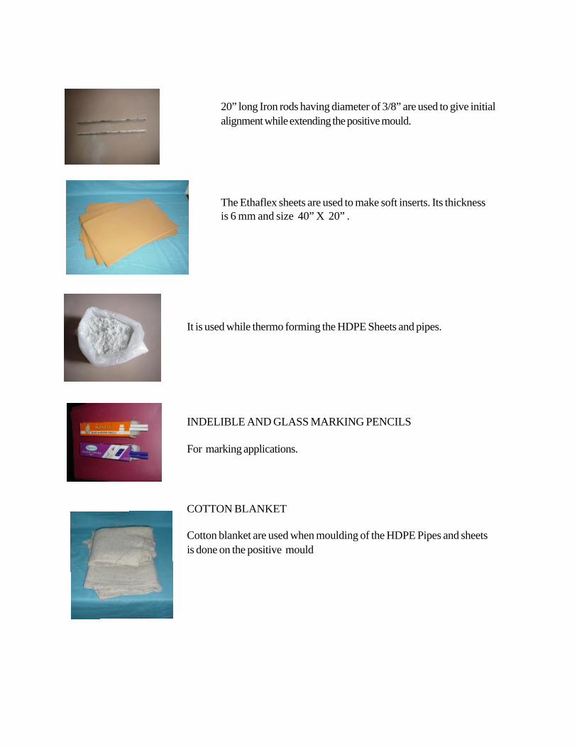
It is used while thermo forming the HDPE Sheets and pipes.
INDELIBLE AND GLASS MARKING PENCILS
For marking applications.
COTTON BLANKET
20” long Iron rods having diameter of 3/8” are used to give initialalignment while extending the positive mould.
The Ethaflex sheets are used to make soft inserts. Its thicknessis 6 mm and size 40” X 20” .
Cotton blanket are used when moulding of the HDPE Pipes and sheetsis done on the positive mould

Chapter 6Tools and Equipments
The following tools and equipments are required to run a Jaipur Foot/Limbworkshop.
1. Hammers2. Scissors3. Screw Drivers4. Files (rasp - half round and round, smooth - round and half round)5. Wood chisels - 2” (Flat)6. Pliers7. Oven (electric or gas)8. Jig Saw machine9. Heat gun10. Drill Machine11. Belt Grinder, Stone Grinder.12. Anvil13. Vacuum pump with connecting kit.14. Drill Bits.15. Buffing wheel (rag wheel)16. Vice17. Knife18. Tri squat or plumb line19. A-P and M-L Caliper20. Working bench21. Measuring tape22. Centre punch23. Sheet cutter24. Hand Drill Machine25. Alignment Transfer Jig26. Alignment Coupling, Ankle Adapter and Extension rods


Chapter 7PTB Socket
The PTB ( patellar tendon bearing ) total contact socket is used in theJaipur Below Knee Prosthesis. The main feature of the technique of fitting thissocket involves extensive modification of many aspects of the shape of the socket,it mainly derived its name from only one of these features: it is modified toapply the load through the strong, broad, patellar tendon. The modification takesthe form of patellar bar which presses in between inferior edge of the patella andtibial tubercle. The counter force is applied by the popliteal area. Care must betaken not to over compress the popliteal vein, common peroneal nerve and tibialnerve. The posterior wall of the PTB socket is in firm contact but is flat. It isnecessary to provide relief for hamstring tendons. The mould is also modified touse the flare of the tibial condyles, especially the medial condyle, for support. Thecrest of the tibia, the head of the fibula, the distal cut end of the tibia and fibulaand sometimes a prominent lateral tibial condyle cannot tolerate stress and mustbe relieved.
Much of the modification of the PTB socket can be achieved at the time ofcasting stage, by the application of manual pressure as the plaster dries. Thepatellar ridge is formed by using the thumb and fingers , with counter pressurein the popliteal area. When this pressure is applied, there is natural tendency forthe cast to bulge medially and laterally which must be controlled.
The proximal border of the PTB socket is designed to provide medio-lateralstability and suspension by extending the lateral and medial aspects of thesocket over the femoral condyles. The maximum height of the proximalborder is limited by the need to avoid the socket wall protruding upward abovethe anterior surface of the thigh when amputee sits. It is important to extend themedial and lateral walls of the socket as far as possible in the case of the shortstumps, in order to increase the lever arm available for medio-lateral stability. Theanterior wall of the socket usually extends over the lower third of the patella; it iscupped to avoid loading the patella excessively and to provide additional rotationalcontrol.
Although a hard socket that has been expertly fitted is usually verysatisfactory, there are amputation limbs that benefit from being fitted with softinserts.
There are several variations in the design of the proximal brim of the belowknee prosthetic sockets. These variants are used to provide suspension; suchsockets are termed as “PTS” (patella tendon-supracondylar). This design enclosesthe femoral condyles and sometimes the patella.

A well fitted PTB total contact socket can overcome the problem of theterminal edema .These sockets provide better sensory feedback to the skin of thestump to enable the amputee to know the position of the stump in the space, inspite of the distance from the ground. Although the major weight -bearing area ispatellar tendon in a PTB socket, it distributes load evenly and reduces pressurethe stump is subjected to.
In short, the design provide a biomechanically efficient system which allowsan amputee to walk faster over a longer distance with an almost imperceptiblelimp.

Chapter 8Fabrication Technique of Jaipur Below Knee Prosthesis
8.2 MeasurementsAfter evaluating the stump, the measurements of stump and sound limb are taken. The measurementsare the most important procedure during the fabrication of a prosthesis , it determines the accuracyof fit and comfort. The measurements are used while modifying the positive mould, to replicate thelength of sound limb and to select the appropriate size of Jaipur Foot.
Stump MeasurementsThe following stump measurements are recorded.
8.2.1. Stump length from head of fibula to distal end of the stump. Head of fibula is easily palpable both on the stump and positive mould. Hence, their areless chances of getting inaccurate stump length. Alternatively, stump lengthcan be measured from inferior edge of patella to distal end of the stump.
8.2.2. Circumference of the stump at mid patellar level, and after every 2”below till distal end of the stump.
8.1 Evaluation of the stumpEvaluation of the stump is necessary to determine the factors whichmay affect the fitting of the prosthesis. It is done by visual inspection and by palpation. The stump is evaluated for joint function, musclestrength, skin condition, scarring and pain. Any information related to these factors is noted and used later on while fabricating theprosthesis.

8.2.6 Length from tip of head of fibula to floor.
8.2.3. A-P dimension: Using a measuring caliper, the Antero-Posteriordimension is recorded from just below the inferior edge of patella topopliteal area. The stump will sink inside the socket if the A-P dimensionis greater than actual. If it is less, then the prosthesis user will alwayscomplain of uncomfortable pressure on mid patella tendon region and there
c are chances of compression of popliteal vein, common peroneal nerve andtibial nerve.
8.2.4. M-L dimension: Using the measuring caliper, the Medio-Lateraldimension is recorded from the widest area medio-laterally of theamputed knee joint. The measurements should be checked two-three times
as this is an important measurement, accuracy of which provide goodmedio-lateral stability. The M-L dimension of the positive mould will alwaysbe greater than actual since the pressure is applied antero-posteriorly by
thumbs and fingers by virtue of which the cast tends to bulgemedially and laterally.
The Sound Limb MeasurementsThe measurements of sound limb are necessary to record as the positive mould is to be replicatedas per the length of sound limb. The following measurements are taken with the help of a tape-measure.
8.2.5 Length from middle of patellar tendon to medial malleolus.
8.2.7 The size of Jaipur Foot.
A Measurement chart should always be suggested to record all these important information andmeasurements so that the same can be used later on during the fabrication procedure.


8.3 Wrap Cast
After completing the procedure of measurements, the Wrap Cast of the amputee’s stump is taken.First of all, the amputee is seated on a firm bench with his/her thigh supported and back of kneeappx. 100 mm from the edge of the chair. Then, a moistened cast sock is pulled over the stump.The amputee is instructed to keep his/her stump in an attitude of 5 to 10 degrees of flexion which ismaintained throughout the casting procedure.
8.3.1 After this, the following pressure sensitive areas of the stump are markedby using an indelible pencil.
1. outline of patella 2. mid patellar tendon3. tibial crest 4. medial tibial flare5. medial border of tibia 6. distal end of tibia
7. head of fibula 8. distal end of fibula if it is prominent9. any other area which is pressure-sensitive
8.3.2 Two plaster of paris bandages are prepared by simply smearing POP powder on cottonbandages. These bandages are, then, submerged in the water. When the bandages areproperly soaked in water, they are taken out and excessive water is squeezed prior to use.
8.3.3 The stump is then wrapped with one of these bandages, lengthwisestarting from the superior edge of patella downwards. These bandagesare wrapped circumferentially up again covering the femoral condyles,appx. 3” above the mid patellar tendon area. This is done carefullywith a firm and even tension. The plaster is worked with the hands,clearly defining bony prominences and features such as medial tibialflare.
8.3.4As the plaster begins to harden, the thumbs are placed at an angle of 30 to45 degree to long axis of tibia, on either side of patellar tendon and pressedinwards. The tips of the thumbs locate the patellar tendon, gauging thedepth of tissue. And posteriorly, the pads of the fingers are pressed intothe popliteal area. Firm pressure is applied with the fingers. The depth of theimpression is determined by the firmness of the tissue. The amputee isinstructed to remain seated with his/her stump muscles relaxed during theWrap Casting procedure. When the wrap has hardened completely, it ispulled off the stump.

8.4 Mould Modification
8.4.1 The next step is to fill the wrap cast with plaster of paris paste. The wrap is fixed in the cast holder.Separating agent like vaseline is applied over the mandrel and sliding rod. Then mandrel is fixed inthe wall frame and POP paste is poured in the wrap cast. The care should be taken not to make plaster of paris paste too thick or too diluted.
8.4.2 When the plaster is set completely, the plaster of paris bandages are slitopen using a knife. Always remember to start cutting from the proximalend of the stump on the middle of anterolateral aspect.
8.4.3 The positive mould of the stump is thus obtained. The pressure sensitive areaswhich were marked earlier are checked and impressions and markings arereinforced once again. Except these areas, the mould is then smoothened by using a wire mesh and stockinette impressions are removed.
8.4.4 The length of positive mould is checked from head of fibula to distal end of thestump. It is compared with the measurements of stump, any discrepancy is recorded for modification.
8.4.5 Similarly, all circumference are checked and the difference from theactual circumferences of the stump is recorded for modification.

8.4.6 The M-L dimension is checked by using measuring caliper.
8.4.7 The A-P dimension is checked by using measuring caliper. Anydifference in both dimensions is recorded. Now, the positive mouldis ready for modification.
The objective of modification is to distribute the contact pressure on the pressure tolerant areasand to remove the pressure from the sensitive areas of the stump. Also to ascertain that themeasurements of the stumps are confirming to the measurements of corresponding area of thepositive mould. The positive mould is modified to distribute even pressure by removing the plasterfrom the pressure tolerant areas and build-ups are made by adding the plaster to provide reliefs onpressure sensitive areas.
8.4.8 The first step in the modification procedure is to scoop out the plaster frominfra patellar region to tubercle of tibia. The thumb impressions taken atthe time of wrap cast, should be removed which will determine the depthand width of the channel created. Similarly, the plaster is removed from thepopliteal area to the extent of omission of finger impressions. After this,the A-P dimension is checked once again. It should be made sure that the depth and width of the channel created at the mid patellar areashould be appx. 1/2” and 1 1/2” respectively and A-P dimension of thepositive mould should confirm to the actual A-P dimension of the stump.Next, at least 1/8” to 3/8” of plaster of paris is removed from medialtibial flare. On the lateral side of the positive mould, plaster is removedbetween 1/8” to 3/8” from 3/4” below the inferior border of fibula to 1”above the distal end of fibula. All the edges are rounded off using a wiremesh, without erasing the markings on the sensitive areas.

8.4.9 After removal of plaster from the positive mould is completed, the build-ups are made on the mouldby adding plaster of paris paste on the pressure sensitive areas which were marked earlier at thetime of wrap cast. About 1/4” of POP paste is applied over the head of fibula, tibial crest, distal endof the tibia, and any other area where relief from pressure is indicated. Build- ups are also made toaccommodate hamstring tendons on the medial and lateral side posteriorly. Also add at least 1/2”
of paste at the distal end of the stump. The positive mould is then thoroughly smoothened andfinished.
The dimensions of the positive mould are once again checked with the measurements of the amputee’s stump.
8.4.10 The length of positive mould form head of fibula to distal end should be1/2” greater then the actual stump length using Information and MeasurementForm.
8.4.11 The A-P dimension of both, the positive mould and the actual, shouldbe the same. If the A-P dimension of the mould is more than actual, thenthe amputees stump will sink inside the socket. And, if it is less, then the amputee will complain of unbearable pain at the patellar region.
8.4.12 The M-L dimensions of the positive mould and the stump should be thesame. Otherwise, any discrepancy in the dimensions would lead todiscomfort for the prosthesis user and loss of medio-lateral stability.
8.4.13 The circumferences of the positive mould should be equal to the recordedcircumferences of the stump.
8.4.14 After checking each measurement, a sign of ok is marked on the mould,signifying that the desired modification is achieved.

8.5 Fabrication of Soft InsertThe soft insert is not indicated for every patient. However, it is onlyindicated where local or systematic disease causing sensory deficit or hypoasthesia/hyperasthesia in the stump. Most commonlyencountered diseases are diabetes mellitus, leprosy, peroneal nervepalsy, sciatic nerve injury etc. Stumps having bad scars, or skingrafts also require soft insert.
8.5.1 For making the soft inserts, three dimensions are taken:Proximal circumference,
Distal circumference
Length of the positive mould.
8.5.2The measurements of the positive mould are transferred on the
sheet as follows. A vertical line is drawn on the ethaflex sheetacross its width, which is 5” longer than the length ofpositive mould. Proximal circumference is added with 1/2”,and a horizontal line is drawn at the top of and half on theeither side of the vertical line. Another horizontal lineis drawn which is equal to the
distal circumference, at the level marked on the vertical line, equalto the length of the mould from the proximal circumference. Now,the both the ends of proximal circumference and distal
circumference are met by drawing the lines which extend tofurther 5”, (till the bottom of the vertical line). A thirdhorizontal line is drawn at the bottom of the vertical line.

8.5.3 The sheet is now cut according to the outer lines and its edges arebevelled using a belt grinder, on the opposite sides.
8.5.4 The glue is applied on both ends.
8.5.5 When it is completely dried, both ends are pasted togetherand pressed by gently hammering the surfaces. Thus, a cone isobtained.
8.5.6 The cone is placed in a preheated oven for 3-5 minutes.
8.5.7 When the sheet becomes malleable, it is pulled over the positive mouldand given the shape by hand moulding. Suction apparatus can also beused for moulding the sheet on to the positive mould. The sheet is then,allowed to cool.

8.5.8 To cover the distal end of the soft insert, a cap is made. For making thecap, the tracing of the distal end of the mould is done directly on theethaflex sheet.
8.5.9 The edges of the cap and of the distal end of the soft insert are bevelledusing belt grinder (soft insert remains on the positive mould).
8.5.10 The glue is applied over the bevelled edges .
8.5.11 When it is dried, the cap is pasted on the distal end.

8.5.12 The proximal brim is lined with sheep skin leather in order to protect thesoft insert from wear and tear, to increase its life and to give a goodcosmetic appearance.
The Soft Insert
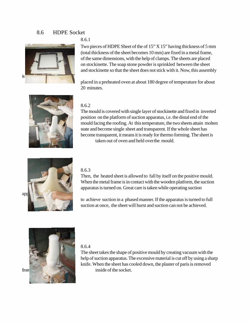
8.6 HDPE Socket8.6.1Two pieces of HDPE Sheet of the of 15” X 15” having thickness of 5 mm(total thickness of the sheet becomes 10 mm) are fixed in a metal frame,of the same dimensions, with the help of clamps. The sheets are placedon stockinette. The soap stone powder is sprinkled between the sheetand stockinette so that the sheet does not stick with it. Now, this assembly
isplaced in a preheated oven at about 180 degree of temperature for about20 minutes.
8.6.2The mould is covered with single layer of stockinette and fixed in invertedposition on the platform of suction apparatus, i.e. the distal end of themould facing the roofing. At this temperature, the two sheets attain moltenstate and become single sheet and transparent. If the whole sheet hasbecome transparent, it means it is ready for thermo forming. The sheet is
taken out of oven and held overthe mould.
8.6.3Then, the heated sheet is allowed to fall by itself on the positive mould.When the metal frame is in contact with the wooden platform, the suctionapparatus is turned on. Great care is taken while operating suction
apparatusto achieve suction in a phased manner. If the apparatus is turned to fullsuction at once, the sheet will burst and suction can not be achieved.
8.6.4The sheet takes the shape of positive mould by creating vacuum with thehelp of suction apparatus. The excessive material is cut off by using a sharpknife. When the sheet has cooled down, the plaster of paris is removed
from inside of the socket.

8.7 Trimlines
8.7.1 Anteriorly, the trimlines cover lower third of patella, then it extends upward medially and laterally.
8.7.2 Medially and laterally, the trimlines cover the femoral condyles andthen start coming down posteriorly ( the height of the medial and lateralsocket brim is limited to need of avoiding wall protrusion upward whenamputee is sitting ).
8.7.3 Posteriorly, the trim line is 1/2” lower on the medial side than the lateral side.This is important as two hamstring tendons are inserting on tibia medially ascompared to single hamstring tendon insertion on the lateral side. In themiddle of posterior aspect, the trim line is 1/2” higher than the patellar tendonso as to give anteriorly directed counter pressure to maintain the patellartendon on its position. Otherwise, the patellar tendon may sink in the socket.
8.7.4 The HDPE socket is cut according to trim lines drawn by usingZig saw machine. Its rough edges are smoothened using rasp file,smooth file and buff wheel.

8.8 Extension of Socket using Endolite Alignment Transfer System
8.8.3 A similar line is also drawn on the lateral aspect of the socket. Thisline shows the amount of flexion in the stump. Both the referencelines will act as guidelines while extending the positive mould.
8.8.2 Secondly, the amputee is asked to stand up in a frame. Make surethat his/her pelvis are leveled. With the help of trisquat, a line isdrawn on centre of the anterior surface of the socket This linedescribes about the varus (adduction) and valgus (abduction) in thestump and will be used as a guide while extending the positivemould.
8.8.1 Next stage in the fabrication procedure is the extension of thesocket. Firstly trial of the socket is taken . The amputee isseated and the stump socks is pulled over his/her stump. TheHDPE socket is put on the stump. The amputee is asked to flexand extend his/her stump several times in order to ascertain that thetrim lines are correct and the amputee is comfortable with the fit ofthe socket.
8.8.4 The Endolite Alignment Transfer System Consists of a Wall Frame,mandrel with sliding rod, and Cast holder. The socket is fixed inthe cast holder with its reference lines in vertical position. Bydropping plumb line, it is ensured that these lines are vertical. Anyinclination can be corrected by loosening the nut in the alignmentcoupling and adjusting the cast holder accordingly. Afteradjustments, the nut is tightened
8.8.5 The mandrel is fixed at the upper end of the wall frame. Thevaseline is applied over the area which will be in contact with plasterand sliding rod. It is ensured that sliding rod is protruding at least 4” and should touch the bottom of distal end of the inside of the

8.8.6 After this, the POP paste is poured into the socket to fill it completely.
8.8.7 When the plaster is hardened completely, the sliding rod is pressed fromabove in order to leave a mark on the distal outer surface of the socket.After getting the desired mark, the sliding rod is moved up and a 3/8” hole is made on the outer distal end of the socket.
8.8.8 The socket, with the help of mandrel, is fixed in a inverted position at the lower end of the wall frame. An iron rod (Size: 3/8”X20”) is placed in the hole made on the outer distal surface which will serve as the guide for extending the socket.
8.8.9 A cone made of ethaflex sheet, is placed on the socket in such a way thattotal length of the assembly comes out to be 2” more than the linear distance from the head of fibula to medial malleolus of the sound limb. Care must betaken so that the iron rod remains in the centre of the cone from all sides.Then, the cone is filled with plaster of paris paste. When plaster is hardened,cone is removed and extension is given the shape of the leg.
8.8.10 The extended positive mould with socket
It should be ensured that the diameter of distal end of the mould should match with the diameter of the malleolar region of Jaipur Foot.

8.8 Extension of Socket using Otto Bock Alignment Transfer System
The trial of the patient and the anterior and lateral reference lines are taken as describedpreviously from 8.8.1 to 8.8.3. After getting the reference lines the following procedure is adoptedto extend the socket using Otto Bock alignment system.
8.8.4 The socket is fixed with a concave disc with plaster of paris paste.Care is taken to fix the socket on disc with its anterior and lateralreference lines absolutely vertical.
8.8.6 Once again, the anterior and lateral reference lines are positioned inabsolute vertical position. The mandrel is already in vertical positionand is in line with anterior and lateral reference lines. Anyangulation can be overcome by screwing and unscrewing the fourscrews provided with the apparatus.
8.8.5 The assembly is fixed on a alignment transfer apparatus. Thisapparatus helps in aligning the mandrel as per the anterior andlateral reference lines.

8.8.9 A cone made of ethaflex sheet, is placed on the socket in such a way thattotal length of the assembly comes out to be 2” more than the lineardistance from the head of fibula to medial malleolus of the sound limb.Care must be taken so that the iron rod remains in the centre of thecone from all sides. Then, the cone is filled with plaster of paris paste.When plaster is hardened, cone is removed and extension is given theshape of the leg.
8.8.7 The socket is then filled with plaster of paris paste.
The positive Extended Mould with Socket8.8.10 It should be ensured that the diameter of distal end of the mould should match with the diameter of the malleolar region of Jaipur Foot.
8.8.8 When the plaster is hardened, a 3/8” hole is made at the distal end ofthe socket. The assembly is then fixed inverted position in a vice. An iron rod(size: 3/8” X 20 ”) is fixed in that hole which is aligned in line withmandrel. This iron rod is again a guide for extending the positive mouldand to reinforce the plaster.

8.9 Fabrication of HDPE Shank
8.9.1 A 24” long HDPE Pipe having diameter of 90 mm is covered withBK Stockinette both from inside and outside. It is important tocover the pipe in this fashion in order to avoid sticking of the same.It is kept in the preheated oven at 180 degree of temperature forabout 30 minutes.
8.9.2 When pipe becomes malleable, it is pulled over the positiveextended mould.
8.9.3 The heated pipe is then given the shape of the mould by handmoulding. The hands continue working for a few minutes untilpipe becomes partially cool. The Extra material is cut off from bothends. When the pipe is completely cooled off, the plaster of parisinside is beaten out either by using a hammer ( impact resistance ofHDPE does not allow it to break when it is beaten by hammer) orby using chisels.
8.9.4 The cutting and finishing is done as per the trimlines of inner socket.For better smoothness of the edges, it is always suggested to usebuff wheels which can be fixed with drill machines.
The HDPE Shank with inner socket inside.

8.10 Trial & Fitting
8.10.1 After making the shank with socket inside, the assembly is nowknown as double-wall socket. The trial of double-wall socket istaken with amputee is seated on the chair or bench. The socketis pulled on the stump with amputee wearing the stump socks.He/she is asked to flex and extend his/her stump several times.The posterior brim of socket should not be hurting in thepopliteal area when it is flexed to maximum extent.
8.10.2 The amputee is then asked to stand erect with the help of supports.A pencil mark is put on the double-wall socket at the level ofmedial malleolus of the sound limb.
8.10.3 This mark is again checked with recorded measurement of headof fibula to medial malleolus of the sound limb. To avoid anyerror and to be on the safer side, another mark just 1/2” belowthe previous mark, should be made. The excess of distal end ofthe double-wall socket is cut from this second mark.
8.10.4 Approximately, 3” area of distal end of the double -wall socket isheated by Heat Gun. After a few minutes, the area will becomemalleable and hold the Jaipur Foot when it is cooled down.
8.10.5 The Jaipur Foot is inserted in the heated area of the double-wall socket.This area is massaged properly in order to avoid any wrinkles, which mightlead to develop cracks in a later phase while being used by the amputee.

8.10.6 The amputee is made to stand wearing the prosthesis. The rotationof Jaipur Foot is Checked.
8.10.7 The length of the prosthesis is checked by palpating the ASIS. Both theASIS should be at same level. To be more sure rubber blocks ofdifferent thickness can be used beneath the amputed side in case theprosthesis is shorter in length. The rubber blocks are placed under thesound limb if the prosthesis is longer. The adjustments are madeaccordingly.
8.10.8 After getting the correct length of the prosthesis, the socket-footassembly is further secured with four screws( size : 8 X 25 ) on each sideof the distal end of the socket. In no case, these screw should behammered in completely. Rather, a small portion should be hammeredand then one drop of feviquick is applied on the threaded portion, andthen, the screws should be tightened with a screwdriver.
8.10.9 The one collar of the leather suspension belt is already riveted. The positionfor other collar is marked on the attachment strap. This is done by placingboth the collars on the medial and lateral half of the socket in such afashion that the movements of the supracondylar strap is not restricted.The location for attaching the loose collar is marked on the attachmentstrap and at the same time markings are also taken on the socket forpasting the attachment strap on the socket. The loose collar is riveted withattachment strap by press buttons. The marked area on the socket is maderough by rasp file, and glue is applied on it and on the attachment strap ofthe belt. The glue is then left to dry out. When it is completely dried, theattachment strap is pasted on the socket and pressed with hammer.

Chapter 9Static & Dynamic Alignment in Jaipur Below Knee Prosthesis
The alignment refers to the relative position of the various components of the prosthesis withrespect to each other, particularly, the socket and foot. The alignment of a prosthesis influences themagnitude and distribution of forces applied to the stump by the socket. From the learning offabrication procedure of Jaipur Below knee Prosthesis so far, it is amply clear that the initialalignment is given at the time of extending the socket by using reference lines. But, still there aresome cases where dynamic alignment is required, e.g. abducted or adducted stumps. Fordynamic alignment, the equipments and material like an alignment coupling, ankle adapter,extension rods, Jaipur Foot with bolt and alignment transfer apparatus are required. The evaluationof stump determines the requirement of dynamic alignment in the Jaipur Below Knee Prosthesis.The process is as follows.
9.1 By Endolite Alignment Transfer SystemThe procedure of evaluation, measurements and wrap cast is the same as described in previous chapters from 8.1 to 8.3.
9.1.1 When wrap cast begins to harden, the amputee is made to stand erect with some support, and is seen that his/her ASIS at same level. The anterior reference line is drawn using trisquat. Similarly, a lateral reference line isalso drawn on the wrap cast
The wrap cast is then pulled off the stump and anterior and lateralreference lines are further reinforced by indelible pencil.
9.1.2. The wrap cast is fixed in the cast holder which is fixed with the lowerend of the wall frame. It is ensured to keep the anterior and lateralreference lines in vertical position. Firstly, the wrap is placed in the sandmaintaining the vertical alignment of the reference lines. A plumb line canbe dropped to see that the lines are vertical. Any inclination can becorrected by alignment coupling below the sand bucket. The mandrel isapplied with the vaseline and inserted from above and fixed with theupper end of the wall frame. After this, the POP paste is filled in the wrap cast.

9.1 By Otto Bock Alignment Transfer System
9.1.1 The anterior and lateral reference lines are drawn in the samemanner as described in 9.1.1.
9.1.2 The wrap cast is fixed on a concave disc using plaster of parispaste. Utmost care should be taken to ensure that both the anteriorand lateral reference lines are vertical.
9.1.3 Then this assembly is fixed on the alignment transfer apparatus.The mandrel is inserted in the wrap cast from above ( vaseline isapplied over the mandrel as separating agent).
9.1.4 If the anterior and lateral reference lines are not vertical, they aremade vertical with the help of four screws provided in the alignmenttransfer jig with which the concave disc is attached.
9.1.5 After setting the reference line in absolute vertical position, thewrap is then filled with plaster of paris paste.

9.1.6 When the POP paste is set, the whole assembly is removed from the alignment transfer zigand mould modification is started. After doing the desired modification as described in8.4, the positive mould is once again fixed in the alignment transfer zig and the anterior andlateral reference lines are remarked on the positive mould. The distal part of the positivemould is additioned with plaster as per following diagrams.
CONDITIONS FOR OPTIMUM ALIGNMENT

9.1.9 The extension rod is fixed with the ankle adapter. The sizeof the rod will be determined by the measurement fromhead of fibula to floor less the length of Jaipur Foot,
9.1.10. A hole is made in the centre of distal end of the socket.The alignment coupling is fitted with the socket.
9.1.7 The soft insert and HDPE socket are made as described inprevious chapters from 8.5 to 8.7.
9.1.8 The Ankle adapter is fixed with Jaipur Foot with bolt. The bolt is kept in vertical position from all sides. The bolt ofJaipur Foot is fully threaded, therefore, the ankle adapter is to be rotated in order to fix it.
9.1.11. All the components are assembledtogether. Now the prosthesis is ready forstatic and dynamic alignment.

9.2 Static Alignment:
The prosthesis is put on the patient, and the static alignment is done.
9.2.1 The length of the prosthesis is checked by asking patient to put on his/her bodyweight equally on both the sides, and by palpating his/her ASIS. The ASISshould be at the level of an imaginary line across them. Any discrepancy in length canbe corrected by replacing the extension rod.
9.2.2 The sole of the Jaipur Foot should be flat on the floor. If it is not flat on the floor,then the nut inside the alignment coupling is loosened and the socket isshifted / tilted on the alignment coupling to achieve the desired result. It is also checked that the bolt of Jaipur Foot is in upright position.
9.3 Dynamic Alignment:
The Gait deviations are seen from front, from behind and from side, when patient iswalking. There are always two causes for any gait deviation: prosthetic and amputee’s.The prosthetic cause can be corrected by changing alignment known as “dynamicalignment”. Whereas, the amputee’s cause may be some pathological condition or habitdeveloped after prolonged use of improperly fitted prosthesis. The three important stagesof gait cycle are observed.
1. Between heel strike to mid-stance 2. At mid-stance 3. Between mid-stance to toe-off
9.3.1 From heel strike to mid-stance
a. Excessive knee flexion
Prosthetic Causes:
1. Excessive anterior tilt of the socket2. The Jaipur Foot is fixed in dorsiflexion

Amputee’s Cause:
Flexion Contracture at knee
Corrections:
1. The nut inside the alignment coupling is loosened and the socket is tilted posteriorly.2. The Jaipur foot is removed from ankle adapter and its bolt is corrected to vertical
position and reattached to the assembly i.e. it is fixed in plantigrade position.3. If the flexion contracture is not fixed, the patient is advised to have it corrected by
passive stretching under the supervision of a physiotherapist. Fixed contractureneeds surgical correction and, hence, the patient should be referred to the surgeon.
b. Insufficient or absent knee flexion
Prosthetic Causes:
1. Excessive posterior tilt of the socket2. The Jaipur Foot is fixed in planter flexion
Corrections:
1. The nut inside the alignment coupling in loosened and the socket is tilted anteriorly to thedesired position.
2. The Jaipur foot is removed from ankle adapter and its bolt is straighten to verticalposition i.e. the Jaipur foot is fixed in a plantigrade position.
9.3.2 At mid-stance
a. Excessive lateral thrust
Cause:
Excessive lateral placement of the socket from the weight bearing line.
Correction:
The nut inside the alignment coupling is loosened and the socket is Shifted medially.

b. Pressure on the medial proximal brim
Cause:
Excessive medial placement of the socket.
Correction:
The nut inside the alignment coupling is loosened and the socket is shifted laterally.
c. Lateral bending of trunk
Causes:
1. Prosthesis is short in length than sound limb.2. Bad gait habit.
Correction:
1. The length of the prosthesis is increased by replacing the extension rod of the correct size.2. Gait training.
d. Inverted or everted foot ( patient walks on the medial or lateral border of the foot )
Cause:
Excessive medial or lateral tilt of the socket.
Correction:
The nut inside the alignment coupling is loosened and the socket is adjusted medially orlaterally to the desired position.
9.3.3 Between mid-stance to toe-off
a. Early knee flexion ( drop-off )
Causes;
1. The socket is fixed anteriorly from the lateral midline of the stump.

2. The Jaipur foot is fixed in dorsi flexion.
Correction:
1. The socket is shifted posteriorly .2. The Jaipur foot is removed from the ankle adapter and reattached in a plantigrade position.
b. Delayed knee flexion
causes:
1. The socket is fixed posteriorly from the lateral midline of the stump.2. Excessive planter flexion of the Jaipur foot.
Corrections;
1. The socket is shifted anteriorly.
2. The Jaipur foot is removed from the ankle adapter and reattached in a plantigrade position.
In Swing Phase
Vaulting
Cause:
The prosthesis is too long.
Correction:
The extension rod is replaced with the rod of correct length.

9.4 Alignment Transfer by using Endolite Alignment Transfer System
9.4.1 After having done the static and dynamic alignment, the Jaipur Foot isremoved from the ankle adapter. The Pylon is fixed with the lower partof the wall frame.
9.4.2 The mandrel is inserted from above and fixed with the upper part of thewall frame. Then, POP paste is poured in the socket.
9.4.3 Next, when the plaster has hardened, the assembly is fixed in a invertedposition with the lower part of the wall frame. The alignment couplingis removed from the socket.
9.4.4 A nylon rod is attached with the protruding bolt of the alignment coupling.This rod acts as a guide for extending the socket and to hold the plaster.
9.4.5 A cone made of ethaflex sheet, is placed on the socket in such a way thattotal length of the assembly comes out to be 2” more than the linear distance from the head of fibula to medial malleolus of the sound limb. Care must betaken so that the rod remains in the centre of the cone from all sides.Then, the cone is filled with plaster of paris paste. When plaster is hardened,cone is removed and extension is given the shape of the leg.

9.4 Alignment Transfer by using Otto Bock Alignment Transfer System
9.4.1 After having done the static and dynamic alignment, the Jaipur Foot isremoved from the ankle adapter. The whole assembly without Jaipur footis fixed with the lower part of the transfer apparatus by means of securingankle adapter with bolt.
9.4.2 The mandrel is inserted in the socket from above which is fixed with thetransfer apparatus. The POP paste is poured in the socket.
9.4.3When the plaster has hardened, the assembly is fixed in avice in a inverted position and a nylon rod is attached withthe protruding bolt with which alignment coupling wasattached earlier. A preformed cone made of ethaflex sheetis tied with the socket as described in 9.4.5. Pop paste ispoured into the cone from above.
The finished extended mould ready for pulling of HDPE pipecovering.
9.4.4 When the plaster is set, the cone is removed and the mould is given the shape of the leg keeping in mind that thediameter of the lower end of the extended mould should beequal to the diameter of the malleolar region of the JaipurFoot.

The HDPE pipe is pulled over the extended positive mould asdescribed in 8.9.
The heated pipe is being given the shape of the extended mould.
When the pipe has cooled down completely, the POP is removedfrom inside and the socket is cut according to the trimlines ofthe inner socket. It is finished and fitted with Jaipur Foot andleather suspension strap ( as per chapter 8.10).
The Jaipur Below Knee Prosthesis


Chapter 10The Checkout of the Jaipur Below Knee Prosthesis
In checkout procedures, the below knee prosthesis is examined for comfort, stability, alignment anduser’s ability to use the prosthesis effectively. The general finish and workmanship is also examined.The prosthesis is examined with the patient standing, walking, and with the prosthesis is removed.It is beneficial to record the observation in a checkout form.

1. Is the prothesis as prescribed?It should be checked that the prosthesis is made as per the prescription. Any deviation from theprescription should be got approved from prescribing authority.
2. Is it easy for the user to don ( put on) and doff (put off ) the Prosthesis?The prosthesis user should be able to put on and off the prosthesis by himself/herself.
Check with the patient standing
The amputee should stand erect , as comfortably as possible, bearing his/her weight equally onboth feet, with the heel centres not more than 100 mm apart.
3. Is the sole of the Jaipur Foot flat on the floor?The sole of the Jaipur foot should be flat. This signifies that the amputee is able to bear equalweight on both the legs. Any inclination observed, needs change in the alignmentof the prosthesis.
4. Is the prosthesis of correct length?The prosthetic side should be of the same length as the sound leg. To check the length of theprosthesis, compare the height of iliac crest level; an imaginary line across the crests should be
parallel to the ground. ASIS and PSIS can also be used as the reference points. If the referencepoints are not at same level, immediate conclusion should not be arrived at that the prosthesis is ofincorrect length. The apparent discrepancy in length may be due to improper donning of theprosthesis, poor fitting of the socket, poor alignment or due to pelvic drop developed due to some
other reasons. After checking all these points, the length of the prosthesis is adjusted.
5. Is the patient free from any pressure in the area of patella tendon or any where else in the stump?As the patellar tendon is major weight bearing area, sometimes the patient complains of pressure inthis area that may be caused by longer length of the prosthesis then the sound leg or smaller A-Pdimension. A poor fit socket may cause pressure any where else on the stump. Painful site of the
stump, bony prominences, neuromas or any other pressure sensitive area should be taken care atthe time of modification of the positive mould. Other wise, the patient may feel unbearable pressureon these areas.
6. Is the patient comfortable while standing with the midlines of the heels not more than 100 mmapart?The amputee is asked if he/she has any pain or discomfort. Specific location of pain or discomfortshould be identified and the reason for that is analyzed.
Check with patient walking
7. Is the patients performance while walking satisfactory?The amputee is allowed to walk at his/her normal speed. He/she is observed from front, behind andside. Any gait deviation is noted. The cause of deviation is analyzed and corrected.

8. Is the patient go up and down on stairs and inclines satisfactorily?The amputee’s ability to go up and down the stairs and inclines should be carefully analyzed. Theattention should be primarily directed to medical-surgical and prosthetic factors. The amputees skillmust be judged in relation to his/her total physical condition and age as well as the adequacy of theprosthesis.
9. Does the patient consider the prosthesis satisfactory as to comfort, function and appearance?The amputee is asked for his/her opinion about the prosthesis. It is tried to obtain his/her views inreference to comfort, stability, effort, and appearance.
10. Is the stump free from abrasion, discoloration, and excessive perspiration immediately after theprosthesis is removed?The amputee’s stump is examined for skin irritation, localized pressure, oedema or any otherindication of poor socket fitting. Areas of redness which usually disappear within ten minutes afterthe removal of the prosthesis are not significant unless accompanied by discomfort. Some redness ofthe skin on the posterior brim is common. Other area of redness, pallor, bluish colour, coldness orexcessive warmth should be noted and cause determined.
If the amputee complains of tightness distally, check for edema of the distal stump. Edemawhich decreases after the socket is removed suggests poor socket fit. Among the possible causesare tightness of the proximal portion of the socket, piston action, or insufficient contact.
The finish and general workmanship is also checked. Leather work should be of first quality. Thesocket brim must be adequately flared and all sharp edges removed. A very sharp edge any whereon the socket can cause discomfort and lacerate the skin, especially in those amputees, whose skinfolds may overlap the socket brim. No cut marks should be left on the brim of the socket. Anycut mark left may lead to development of the cracks within no time. The screws should not behammered in the socket while fixing the Jaipur foot with the socket. Instead, the one third portion ofthe screw should be hammered first and then it is tightened with screw driver.


Chapter 11Your and Your Patient’s Responsibilities
For your patient’s prosthesis to work at maximum efficiency, you need togive an intimate fit to the socket, maintaining a good alignment. While socket fitand alignment are your responsibility, there is another factor that affect the workingof a prosthesis is skin care. Now that you have produced a good prosthesis, youshould see that your patient is
1. able to don and doff the prosthesis by himself/herself.2. able to maintain good standing balance and to transfer body weight from foot
to foot.3. able to walk on plane surfaces at first, then on slopes, uneven and soft
grounds.4. able to climb stairs.5. able to rise from the floor without anybody’s support.6. able to examine his/her stump after removal of prosthesis.
The patient should be made aware of the most important rule “the communication”. It is very important to tell your patient that he/she shouldinform to you immediately if any thing is wrong during the process of fitment of theprosthesis and learning to use it.
Before your patient leaves your clinic, a few handy tips regarding skin careand general exercises should be given to him/her.
Tell your patient that the care of skin is his/her responsibility. The stump isencased in a somewhat airtight socket which does not breathe and allow the sweatto evaporate. If the sweat is left on the skin and inside the socket, bacteria cangrow. And if the skin is broken, infections can occur. To avoid skin problems, askyour patient to follow these simple steps.
1. Every day or more often, the stump should be washed with mild orantibacterial soap and it should be rinsed well.
2. Everyday wash the stump socks with mild or antibacterial soap and rinsethem well. It is very necessary to remove every bit of the soap from thesocks. The inside of the socket should also be washed and rinsed properly.
3. The stump should not be shaven. Shaving can cause ingrown hairs andoften leads to infected hair follicles.
4. Use locally available oils or softening creams when skin is at risk of crackingor peeling.
5. The alcohol-based products should not be used on the stump. They dry outthe skin and can cracking or peeling and create a potential site ofinfection.

6. The thinnest dressing possible should be used if an abrasion needs to becovered. Bulky padding will increase the pressure inside the socket.
7. The soft material should not be added like extra cloth to pad a pressuresore. This will only add more pressure.
8. If the fit of the socket is changed, try to adjust it with increasing or decreasingthe layers of stump socks. If problem persists, then he/she should visit youfor the needful.
9. Ask your patients to try to maintain their weight.10. Suggest your patients to visit and seek medical help if problem like rashes,
blisters ulcers, or infections local or disseminated occur.
General Exercises
Exercises play an important role in rehabilitation of the amputee. Some ofthe benefits of exercise include an increase blood flow to the contracting muscles;prevention of tissue adhesion; help in the control of edema; a decrease in residuallimb hypersensitivity; an improvement in the muscle power; joint range of motion;and coordination; and development of proprioceptive awareness when using limbsensation. The patient should be told to make a routine of doing the exercises.Active stretching and strengthening exercises of stump and sound limb should betold to him/her.

Chapter 12Some Common Stump Problems
The Painful StumpNeuroma
Early after surgery, the divided nerves form neuromata which are sensitive and often produceabnormal sensations in the missing extremities. These symptoms subside with time. If a neuromabecomes adherent to the cut end of a bone, or lies in such a position that it is compressed by theprosthesis socket, it may become a source of continuing pain. Special care must be taken at thetime of mould modification to build-up reliefs for such sites.
Phantom Limb
Every new amputee experiences some sensation in an amputed limb. The discomfort from thephantom is short lived and easily controlled with simple medication. In rare cases, a painfulsensation persists long after amputation which are characterized by bizarre features: the patient mayclaim that his/her fingers are tightly clenched, or that there is a flowing pain in the foot. In contrastto the neuroma, the discomfort from a phantom is usually worse without the prosthesis than withone, and is relieved by the use of a prosthesis.
Skin Lesions of the Stump
Lesions of the skin of an amputed stump are almost exclusively the result of poorly fitted and alignedsockets that produce localized areas of pressure on the stump. They are most frequent in individualswith excessively hairy skin, and include blisters, abrasion etc. Nearly all can be corrected byadjustments of the prosthesis socket
Joint Contractures
Frequently, patients arrive with contractures. This is a common feature in old age patients, sincepositions of flexion provide relief of the pain caused by vascular insufficiency. Some degreeof contractures can be accommodated in the prosthesis. The higher degree of contractures needtreatment. The method of treatment depends upon the patient’s condition and tolerance, andwhether the contracture is fixed or not. The patient with higher degrees of contracture which cannot be accommodated in the prosthesis, should be referred to a physiotherapist for passive
stretchingin non-fixed contractures. The patients should be referred for medical advise in case the contractureis fixed type.

Adherent scar
The amputation limb may have scar areas which may breakdown when subjected to weight-bearingstress. Proper care must be taken to provide prosthesis to such patients having adherent scar ontheir stumps.
Edema
One must be aware that the fluctuations in amputed limb size may continue for 1 to 2 years afteramputation. Proper positioning of the patient in the bed and while sitting, including elevation ofthe amputed limb as well as active exercises help control edema. The patient should be asked to usean alternative method to control edema when the prosthesis is not in use.
However, with the patient who have been using prothesis for quite some time, the edema is theresult of poorly fitted sockets. When the proximal aspect of the socket is too tight and the distalaspect is loose, it results in the terminal edema. The intimate and proper fit of the socket is ofgreat importance to control edema.
Choaking of the Stump
An ill-fitting socket constrict the proximal stump and cause passive venous congestion of the end ofthe stump. It commonly occurs as the result of shrinkage of the stump permitting it to sink into thesocket. The cynosed, pigmented and edematous skin is the characteristic of the Choaking of thestump. More skillful fitting of total contact socket can largely eliminate this problem
Skin Grafts
The skin grafts on the stump are anaesthetic, and break down easily by rubbing against the insideof the socket. However, the skin grafting is done on the stump in order to save considerable amountof stump function of the patient. In such cases, the socket should be provided with soft padding orlining to protect the grafted area from breakdown.

Tarun Kumar KulshreshthaProsthetist & Orthotist,
Senior Manager,Bhagwan Mahaveer Viklang Sahayata Samiti
(New Delhi Branch),Ahimsa Bhawan, Shankar Road,
New Delhi-110060.Telephone: 25785133
Email : [email protected]