the islamic university of gaza - library.iugaza.edu.ps · iii abstract this study investigates the...
TRANSCRIPT


IV
April - 2013
The Islamic University of Gaza Deanship of Higher Studies Faculty of Engineering Civil Engineering Department
Design and Rehabilitation of
Structures.
Submitted By:
Yasser Mahrosse Owayda
Supervisor:
Prof. Samir Shihada
ـزةـــــغــ – الميــةـــامعــة الإلســالج ـليـــاــــــدراســات الـعـــــــــمــادة الــــــع
كـلـيــــــــــة الـهــــــندســـــــة قـســـــم الـــهـنـدســـــــــــة المدنية
تصميم وتأهيل المنشئات
Strengthening and Repair of RC Beams
with Cemintitions Repair Materials
Strengthening and Repair of RC Beams
with Cementitious Repair Materials
تقوية وإصالح الكمرات الخرسانية بإستخدام مواد
اإلصالح اإلسمنتية
A Thesis Submitted in Partial Fulfillment of the Requirements for Degree of
Master of Science in Civil Engineering - Rehabilitation and Design of Structures

ii

iii
ABSTRACT
This study investigates the flexural capacity, deflection and crack patterns of reinforced concrete
beams repaired by application of four repair materials, Ultra High Performance Concrete, Ultra
High Performance Fiber Reinforced Concrete, Ordinary Portland Concrete, and special repair
materials for repair of three types of damages that can occur in construction. These include over
loading cracks, honeycombing, and spalling of concrete cover due to elevated temperature. It is
also intended to assess the feasibility of using these repair materials in repair and strengthening
of damaged reinforced concrete beams. A series of four point flexural tests was conducted on
both damaged and undamaged reinforced concrete beams to evaluate the performance of the
damaged reinforced concrete beams after application of the repair materials. The conducted tests
yielded complete load–deflection curves from which the increase in flexural capacity was
evaluated. The results show that the repair materials are capable increasing the flexural capacity,
deflection and improving crack pattern, and are effective in strengthening and repair of damaged
RC beams. The results of the investigation will be used to develop design guidelines governing
the use of these repair materials in the field of repair and strengthening of damaged reinforced
concrete beams. The cracked beams which were repaired using UHPC, UHPFRC, OPC and
SRM developed flexural strengths 8, 19, 3.17, 11% respectively, higher than the undamaged
beams. The honeycombed beams which were repaired using UHPC, UHPFRC, OPC and SRM
developed flexural strengths 19, 30, 1.50, 27% respectively, higher than the undamaged beams.
And the heated beams which were repaired using UHPC, UHPFRC, OPC and SRM developed
flexural strengths 1.50, 6.60, 0.00, 3.70% respectively, higher than the undamaged beams.

iv
ملخص البحث
خرسانة ،االحزمة الخرسانية المسلحة باستخدام اربعة مواد معالجة وهي خرسانة عالية االداءتتناول هذه الدراسة معالجة وتقوية
و مادة معالجة كيميائية جاهزة مصنعة من احد شركات المختصة في ،خرسانة عادية ،عالية االداء مضاف لها الياف معدنية
د واثناء التنفيذ وهي ظهور تشققات في االحزمة, وجمواد المعالجة , لعالج ثالث مشاكل في االحزمة الخرسانية قد تنشأ
مدى تعشيش في االحزمة بعد عملية الصب, وتعرض االحزمة لدرجة حرارة عالية تفقدها الغطاء الخرساني , وذلك للتحقق من
ط, وتشكل قيمة الترخيم والهبو ،تأثير تلك المواد على االحزمة الخرسانية المتضررة من حيث قوة التحمل في االنحناء
عمل فحص التحميل ذو االربع نقاط على االحزمة المعالجة واالحزمة المرجعية تم المعالجة. ةالتشققات على االحزمة الخرساني
أظهرت النتائج ان المواد المستخدمة في البحث لها القدرة لتقييم تأثير تلك المواد على االحزمة الخرسانية المسلحة بعد تطبيقها.
يادة قوة تحمل االنحناء وقيم الترخيم والهبوط كما وحسنت شكل التشققات لالحزمة الخرسانية المعالجة. وسيتم على تحسين وز
التي تحكم استخدام تلك المواد في معالجة وتقوية االحزمة في التصميم يستند اليهااستخدام نتائج الدراسة في وضع مبادي
لتحمل المقطع في االنحناء المعالجة بتلك المواد حسنت قوة ا التي بها تشققات حيث ان االحزمة الخرسانية الخرسانية المسلحة.
، بينما ان االحزمة الخرسانية التي بها تعشيش والمعالجة بنفس المواد متضررةمقارنةبالكمراتالغير،%بالترتيب8,91,7.93,99
راتالغيرمتضررة ، اما االحزمة الخرسانية %بالترتيب،مقارنةبالكم91،73,9.03،93حسنت قوة التحمل المقطع في االنحناء
7.3، 3.33، 6.6، 9.03التي تعرضت لدرجة حرارة عالية والمعالجة بنفس المواد حسنت قوة التحمل المقطع في االنحناء
.% بالترتيب ،مقارنةبالكمراتالغيرمتضررة .

v
DEDICATION
This thesis is dedicated to my parents who have
supported me all the way since the beginning of my studies.
In addition, this thesis is dedicated to my wife who has
been a great source of motivation and inspiration.
Finally, this thesis is dedicated to all those who believe in the
richness of learning.

vi
ACKNOWLEDGEMENT
Foremost, I would like to express my sincere gratitude to
my advisor Prof. Samir Shihada for the continuous support
during my study and research, for his patience, motivation,
enthusiasm, and immense knowledge. His guidance helped me in
all the time of research and writing of this thesis. I could not
have imagined having a better advisor and mentor for my
study.
I am extremely grateful to the staff of the Laboratory
of the Engineers Association and the Islamic University
Material and Soil Laboratory.
The informal support and encouragement of many friends
has been indispensable.
My parents have been a constant source of support –
emotional, moral and of course financial – during my
postgraduate years, and this thesis would certainly not have
existed without them.
My wife Rasha has been, always, my pillar, my joy and my
guiding light, and I thank her.
Finally thank my sons, Mahrosse, Mohammed, and Musab
who Supported me in my profession and my ambition altitude
in this life.
vii
TABLE OF CONTENTS
Abstract………………………………………………………………………..…...…………… III
Dedication……………………………………………………………………..……….....……… V
Acknowledgement ………………………………………………………………………...……………..……… VI
CHAPTER 1 INTRODUCTION .................................................................................................................... 1
1.1. INTRODUCTION: ................................................................................................................................... 1 1.2. PROBLEM STATEMENT: ......................................................................................................................... 2 1.3. RESEARCH OBJECTIVES: ....................................................................................................................... 2 1.4. METHODOLOGY: .................................................................................................................................. 3 1.5. THESIS STRUCTURE: ............................................................................................................................. 3
CHAPTER 2 LITERATURE REVIEW ......................................................................................................... 4
2.1. INTRODUCTION: ................................................................................................................................... 4 2.2. PREVIOUS STUDIES RELATED TO USING UHPFRC AS A REPAIR MATERIAL: .............................................. 5 2.3. PREVIOUS STUDIES RELATED TO USING UHPC AS A REPAIR MATERIAL: .................................................. 8 2.4. PREVIOUS STUDIES RELATED TO USING OPC & SPECIAL REPAIR MATERIALS AS A REPAIR MATERIALS: ..... 9
CHAPTER 3 EXPERMENTAL DETAILS...................................................................................................12
3.1. INTRODUCTION: ..................................................................................................................................12 3.2. MATERIAL PROPERTIES: ......................................................................................................................14
3.2.1. UHPC Properties:..........................................................................................................................14 3.2.2. UHPFRC Properties: .....................................................................................................................15 3.2.3. OPC Properties: ............................................................................................................................16 3.2.4. Special Repair Materials: ...............................................................................................................16
3.3. CRACKED BEAMS ................................................................................................................................17 3.3.1. Beam geometry: .............................................................................................................................17 3.3.2. Calculation of flexural capacity of the beam section: ......................................................................18 3.3.3. Number of tested samples: ..............................................................................................................18 3.3.4. Testing procedure: .........................................................................................................................19
3.4. HONEYCOMBED BEAMS .......................................................................................................................20 3.4.1. Beam geometry ..............................................................................................................................20 3.4.2. Calculation of flexural capacity of the section: ...............................................................................21 3.4.3. Number of tested samples: ..............................................................................................................21 3.4.4. Testing procedure: .........................................................................................................................21
3.5. HEATED BEAMS ..................................................................................................................................22 3.5.1. Beam geometry and material properties..........................................................................................22 3.5.2. Calculation of flexural bearing capacity of the section: ...................................................................22 3.5.3. Number of tested samples: ..............................................................................................................23 3.5.4. Testing procedure: .........................................................................................................................24
CHAPTER 4 REPAIR OF CRACKED BEAMS ..........................................................................................25
4.1. INTRODUCTION: ..................................................................................................................................25 4.2. CONTROL BEAM SAMPLE TESTING: .......................................................................................................26 4.3. CRACKED BEAMS AFTER REPAIR:..........................................................................................................28
4.3.1. Repairing the cracked beams using UHPC: ....................................................................................29 4.3.2. Repair of cracked beam by using UHPFRC: ...................................................................................32 4.3.3. Repairing cracked beams using OPC: ............................................................................................34 4.3.4. Repairing cracked beams using special Repair Material (SRM): .....................................................36
4.4. DISCUSSION OF RESULT: ......................................................................................................................39 4.4.1. Flexural capacity ...........................................................................................................................39 4.4.2. Mid-Span deflections:.....................................................................................................................41 4.4.3. Crack patterns: ..............................................................................................................................44
CHAPTER 5 REPAIR OF HONEYCOMBED BEAMS...............................................................................46

viii
5.1. INTRODUCTION: ..................................................................................................................................46 5.2. CAUSES OF HONEYCOMB:.....................................................................................................................47 5.3. PREVENTION OF HONEYCOMB: .............................................................................................................48
5.3.1. Concrete preparation: ....................................................................................................................48 5.3.2. Forming and rebar placement: .......................................................................................................48 5.3.3. Concrete placement: ......................................................................................................................49
5.4. REPAIR PROCESS: ................................................................................................................................49 5.4.1. Defining the size and depth: ...........................................................................................................50 5.4.2. Removal Techniques: .....................................................................................................................50 5.4.3. Repair Materials and placement techniques:...................................................................................51
5.5. CONTROL BEAM TESTING: ....................................................................................................................51 5.6. TESTING OF REPAIRED HONEYCOMBED BEAMS: ...................................................................................53
5.6.1. Repair of Honeycombed beams using UHPC: .................................................................................55 5.6.2. Repair a Honeycombed beams using UHPFRC: .............................................................................57 5.6.3. Repair of Honeycombed beams using OPC: ....................................................................................59 5.6.4. Repair of Honeycombed beams using Special Repair Material: .......................................................61
5.7. RESULTS DISCUSSION: .........................................................................................................................63 5.7.1. Flexural capacity: ..........................................................................................................................63 5.7.2. Mid Span Deflections: ....................................................................................................................65 5.7.3. Crack patterns: ..............................................................................................................................68
CHAPTER 6 REPAIRED OF HEATED BEAMS ........................................................................................70
6.1. INTRODUCTION: ..................................................................................................................................70 6.2. DEFINITION OF SPALLING: ...................................................................................................................70 6.3. EFFECT AND CONSEQUENCE OF EXPLOSIVE SAPLLING: ...........................................................................70 6.4. FACTORS INFLUENCING SAPLLING: ......................................................................................................71 6.5. CONTROL BEAM TESTING: ....................................................................................................................72 6.6. HEATED BEAMS AFTER REPAIR: ............................................................................................................74
6.6.1. Repairing the heated beams using UHPC: ......................................................................................76 6.6.2. Repair of Heated beams using UHPFRC: .......................................................................................78 6.6.3. Repairing Heated beams using OPC: .............................................................................................80 6.6.4. Repairing Heated beams using SRM: ..............................................................................................82
6.7. DISCUSSION OF RESULT: ......................................................................................................................84 6.7.1. Flexural capacity: ..........................................................................................................................84 6.7.2. Mid Span Deflection: .....................................................................................................................86 6.7.3. Crack patterns: ..............................................................................................................................89
CHAPTER 7 CONCLUSIONS AND RECOMMENDATIONS ...................................................................91
7.1. CONCLUSIONS: ....................................................................................................................................91 7.2. RECOMMENDATION: ............................................................................................................................94
REFERENCES ...................................................................................................................................................95

ix
LIST OF FIGURES
Figure 3-1: Testing Program Flow Chart ...................................................................................13
Figure 3-2: Cracked Beam (a) layout and (b) Cross section .......................................................17 Figure 3-3: Honeycomb Beam (a) layout and (b) Cross section .................................................20
Figure 3-4: Heated Beam (a) layout and (b) Cross section .........................................................22 Figure 4-1: Crack pattern of the control beams ..........................................................................26
Figure 4-2: Mid - Span displacement .........................................................................................27 Figure 4-3: Sample being cracked .............................................................................................28
Figure 4-4: Crack Groves ..........................................................................................................28 Figure 4-5: Cleaning Samples by Water ....................................................................................29
Figure 4-6: Applying UHPC matrix to the Cracked beams ........................................................30 Figure 4-7: Cracked beam repaired by UHPC and its Crack Pattern ...........................................30
Figure 4-8: Displacement – load curve for cracked beams repaired using UHPC .......................31 Figure 4-9: Applying UHPFRC matrix to cracked beams ..........................................................32
Figure 4-10: Cracking pattern of cracked beams repaired by UHPFRC ......................................33 Figure 4-11: Displacement – load curve for cracked beam repaired by UHPFRC ......................34
Figure 4-12: Applying OPC matrix to Cracked beams ...............................................................34 Figure 4-13: Cracking Pattern for cracked beams repaired by OPC ............................................35 Figure 4-14: Displacement – load curve for cracked beam repaired by OPC ..............................36
Figure 4-15: Applying RM matrix to Cracked Beams ................................................................36 Figure 4-16: Cracking Pattern for cracked beams repaired by SRM ...........................................37
Figure 4-17: Displacement – load curve for cracked beam repaired by SRM .............................38 Figure 4-18: Load - Deflection Relationship ..............................................................................43
Figure 4-19: Crack pattern comparisons ....................................................................................45 Figure 5-1: Honeycomb in a column due to excessive lift depth ................................................46
Figure 5-2: Crack pattern of control beams ................................................................................52 Figure 5-3: Mid-span Displacement...........................................................................................53
Figure 5-4: Cleaning the honeycomb hamples ...........................................................................53 Figure 5-5: Hand Blasting Honeycomb Area .............................................................................54
Figure 5-6: chipping the sample by water ..................................................................................54 Figure 5-7: Applying UHPC matrix on Honeycombed beams ....................................................55
Figure 5-8: Honeycombed beam repaired, and its crack pattern .................................................55 Figure 5-9: Displacement – load curve for honeycombed beams repaired by UHPC ..................56
Figure 5-10: Applying UHPFRC matrix to Honeycombed beams .............................................57 Figure 5-11: Honeycombed beams repaired, and its crack pattern ..............................................57
Figure 5-12: Displacement – load curve for honeycombed beams repaired by UHPFRC ...........58 Figure 5-13: Applying OPC matrix on honeycombed beams .....................................................59
Figure 5-14: Honeycomb beam repaired by OPC tested, and its crack pattern ............................59 Figure 5-15: Displacement – load curve for Honeycombed beam repaired by OPC ...................60
Figure 5-16: Applying RM matrix on Honeycombed beam .......................................................61 Figure 5-17: Honeycomb beams repaired by SRM tested, and its crack pattern .........................61
Figure 5-18: Displacement – load curve for Honeycombed beams repaired by SRM .................62 Figure 5-19: Load - deflection relationship ................................................................................67
Figure 5-20: Crack pattern comparisons ....................................................................................69 Figure 6-1: Crack Pattern of Control Beams ..............................................................................72
Figure 6-2: : Mid Span Displacement ........................................................................................73 Figure 6-3: Beam Samples Heated.............................................................................................74
Figure 6-4: Heated beam get cooled ..........................................................................................74

x
Figure 6-5: chip the concrete cover of the heated samples .........................................................75
Figure 6-6: Cleaning the samples by Water ...............................................................................75 Figure 6-7: Applying UHPC matrix to the heated beams ...........................................................76
Figure 6-8: Heated beams repaired by UHPC tested , and its crack pattern ................................76 Figure 6-9: Displacement – load curve for heated beams repaired using UHPC .........................77
Figure 6-10: Applying UHPC matrix to the heated beams .........................................................78 Figure 6-11: Heated beam repaired by UHPFRC tested , and its Crack Pattern ..........................78
Figure 6-12: Displacement – load curve for heated beam repaired by UHPFRC ........................79 Figure 6-13: Applying OPC matrix to Heated beams .................................................................80
Figure 6-14: Heated beam repaired by OPC tested , and its Crack Pattern..................................80 Figure 6-15: Displacement – load curve for cracked beam repaired by OPC ..............................81
Figure 6-16: Applying RM matrix to Heated beams ..................................................................82 Figure 6-17: Heated beam repaired by SRM tested , and its Crack Pattern .................................82
Figure 6-18: Displacement – load curve for cracked beam repaired by SRM .............................83 Figure 6-19: Load - Deflection Relationship ..............................................................................88
Figure 6-20: Crack PatternS Comparisons .................................................................................90

xi
LIST OF TABLES
Table 3-1: UHPC composition ..................................................................................................14
Table 3-2: properties of steel fibers. ..........................................................................................15 Table 3-3: UHPFRC composition ..............................................................................................15
Table 3-4: OPC composition .....................................................................................................16 Table 4-1: Control beam deflections ..........................................................................................27
Table 4-2: Deflection of UHPC repaired samples ......................................................................31 Table 4-3: UHPFRC sample Deflections ...................................................................................33
Table 4-4: OPC Deflection ........................................................................................................35 Table 4-5: SRM Deflection .......................................................................................................37
Table 4-6: Flexural capacity comparisons ..................................................................................40 Table 4-7: Mid-span comparisons..............................................................................................42
Table 5-1: Control Beam Deflections ........................................................................................52 Table 5-2: deflection of repaired beams by UHPC .....................................................................56
Table 5-3: UHPFRC Deflection.................................................................................................58 Table 5-4: OPC Deflection ........................................................................................................60
Table 5-5: RM Deflection .........................................................................................................62 Table 5-6: Flexural capacity comparisons ..................................................................................64 Table 5-7: Deflection Comparisons ...........................................................................................66
Table 6-1: control beam deflections ...........................................................................................73 Table 6-2: Deflection of UHPC Repaired Samples ....................................................................77
Table 6-3: UHPFRC sample Deflections ...................................................................................79 Table 6-4: OPC Deflection ........................................................................................................81
Table 6-5: SRM Deflection .......................................................................................................83 Table 6-6: Flexural Capacity Comparison .................................................................................85
Table 6-7: Deflection Comparison .............................................................................................87

xii
ABBREVIATIONS
ACI American Concrete Institute. IUG Islamic University of Gaza.
UHPC Ultra High Performance Concrete.
UHPFRC Ultra High Performance Fiber Reinforced Concrete.
OPC Ordinary Portland Concrete.
HPFRCC High Performance Fiber-Reinforced Cementitious Composite.
SRM Special Repair Materials.
C.B Control Beam.
FRP Fiber Reinforced Polymer.
RC Reinforced Concrete.

1
CHAPTER 1 INTRODUCTION
1.1. Introduction:
Reinforced concrete is the most frequently applied structural material in the practice of
civil engineering. By virtue of its good characteristics such as durability, compressive
strength, hardness, fire resistance and workability, it is used in a wide variety of
buildings and construction projects. As durable and strong as it is, the commonly held
view that concrete is a maintenance-free construction material has been challenged in
recent years.
Many reinforced concrete structures may be damaged. Most of them are suffering from
various deteriorations, which may be attributed to cracks, spalling, large deflection, etc.
Many factors are at the origin of these deteriorations, such as aging, corrosion of steel,
earthquake, environmental effects and accidental impacts on the structure. Nowadays, it
is necessary to find repair techniques suitable in terms of economy and speed of
execution.
In this study, the focus was on three problems that occur frequently in reinforced
concrete beams and their repair techniques. The first problem involves excessive
cracking due to overloading, which allows aggressive environmental factors to affect
concrete. This in turn causes more deterioration such as corrosion of steel and spalling
of concrete. The second problem involves honeycombing. The third problem is caused
by spalling of concrete cover during exposure to elevated temperatures.
The repair techniques which are to be used for repair of mentined deteriorations include:
using Ultra High Performance Concrete (UHPC), Ultra High Performance Fiber
Reinforced Concrete (UHPFRC), Ordinary Portland Concrete (OPC), and Special
Repair Materials from a certified manufacturer (SRM).

2
1.2. Problem Statement:
The Rehabilitation and reconstruction of concrete building structures is becoming a
major problem worldwide. New materials and improved cost-effective techniques of
rehabilitating and strengthening in an innovative manner are urgently sought.
The function of concrete in reinforced concrete beams is to bear the loads in the
compression zones and to make a good encasement for steel rebar under normal
conditions. On the other hand, the previously stated problem (excessive cracks,
honeycombing, and separation of concrete cover) allows for aggressive environmental
factors to ingress in concrete to reach steel rebar. This speeds up the process of rusting,
which in turn causes separation and loss of adhesion of concrete with steel rebar. This
reduces the bearing capacity of RC elements, which may causes in failure and losses in
life and property.
Add to this, the abnormal conditions in the Gaza Strip caused by shelling and bombing
caused by the Israeli enemy, causes additional damages to structures. This requires
suitable repair and strengthening techniques to treat these problems using available and
suitable repair materials at the local markets.
1.3. Research Objectives:
The main objectives of the study include the following:
(1) Applying the four-repair technique.
(2) Deciding on the best repair technique in terms of cost and efficiency.

3
1.4. Methodology:
To achieve the objectives of this research, the following tasks were executed:
1. Conducting literature review related to the subject.
2. Casting a large number of reinforced concrete beam samples, some of the
samples are to be cracked through overloading, leaving missing part of the beam
(honeycombing), and heating to 250 Co for 4 hours duration.
3. Applying each of repair techniques on every repair problem, and evaluating the
strength of the beams after repair.
4. Conducting a comparison between the results of the control beams and the
repaired ones.
5. Deciding on the best repair technique for each of the repair problems.
1.5. Thesis structure:
This thesis consists of seven chapters arranged carefully in the order to make it clear
and understandable. This section presents a brief description of these chapters.
Chapter (1): In this chapter statement of problem, objectives of
the research, and the methodology adopted in the research are included.
Chapter (2): Provides a general review of relevant previous studies and the main
constituent materials.
Chapter (3): Discuses the experimental details, experimental program, dimension of
samples that used, materials properties (quantity, quality) that used .
Chapter (4): Discussion and analysis of test results for repair cracked, overview about
types of cracks and how to prevent or minimize it.
Chapter (5): Discussion and analysis of test results for repair honeycombing beam,
overview about types of honeycombing and how to prevent or minimize it.
Chapter (6): Discussion and analysis of test results for repair heated beam.
Chapter (7): Conclusions and Recomendation.
Chapter (8): Refrences.

4
CHAPTER 2 LITERATURE REVIEW
2.1. Introduction:
This chapter provides an overview of previous studies related to the subject of this
research work. It introduces the framework for the case study that comprises the focus
of the research described in this thesis.
It is important to set the context of the literature review work by providing:
- An explanation of its specific purpose for this particular case study.
- Comments on the previous treatment of the broad topic of knowledge sharing.
- An indication of scope of the work presented in this chapter.
The main purpose of the literature review work is to survey previous studies on
knowledge sharing. This is done in order to scope out the key data collection
requirements for the primary research to be conducted, and it formed part of the
emergent research design process.
The approach adopted is in line with current practice in grounded research work. It is
now regarded as acceptable for researchers to familiarize themselves with existing
research prior to collecting their own data.
5
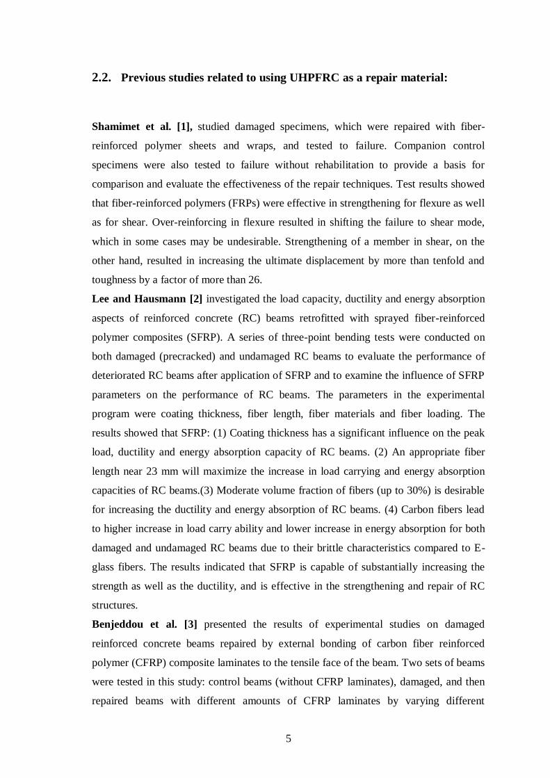
2.2. Previous studies related to using UHPFRC as a repair material:
Shamimet et al. [1], studied damaged specimens, which were repaired with fiber-
reinforced polymer sheets and wraps, and tested to failure. Companion control
specimens were also tested to failure without rehabilitation to provide a basis for
comparison and evaluate the effectiveness of the repair techniques. Test results showed
that fiber-reinforced polymers (FRPs) were effective in strengthening for flexure as well
as for shear. Over-reinforcing in flexure resulted in shifting the failure to shear mode,
which in some cases may be undesirable. Strengthening of a member in shear, on the
other hand, resulted in increasing the ultimate displacement by more than tenfold and
toughness by a factor of more than 26.
Lee and Hausmann [2] investigated the load capacity, ductility and energy absorption
aspects of reinforced concrete (RC) beams retrofitted with sprayed fiber-reinforced
polymer composites (SFRP). A series of three-point bending tests were conducted on
both damaged (precracked) and undamaged RC beams to evaluate the performance of
deteriorated RC beams after application of SFRP and to examine the influence of SFRP
parameters on the performance of RC beams. The parameters in the experimental
program were coating thickness, fiber length, fiber materials and fiber loading. The
results showed that SFRP: (1) Coating thickness has a significant influence on the peak
load, ductility and energy absorption capacity of RC beams. (2) An appropriate fiber
length near 23 mm will maximize the increase in load carrying and energy absorption
capacities of RC beams.(3) Moderate volume fraction of fibers (up to 30%) is desirable
for increasing the ductility and energy absorption of RC beams. (4) Carbon fibers lead
to higher increase in load carry ability and lower increase in energy absorption for both
damaged and undamaged RC beams due to their brittle characteristics compared to E-
glass fibers. The results indicated that SFRP is capable of substantially increasing the
strength as well as the ductility, and is effective in the strengthening and repair of RC
structures.
Benjeddou et al. [3] presented the results of experimental studies on damaged
reinforced concrete beams repaired by external bonding of carbon fiber reinforced
polymer (CFRP) composite laminates to the tensile face of the beam. Two sets of beams
were tested in this study: control beams (without CFRP laminates), damaged, and then
repaired beams with different amounts of CFRP laminates by varying different

6
parameters (damage degree, CFRP laminate width, concrete strength class). Repairing
damaged RC beams with externally bonded CFRP laminates were successful for
different degrees of damage. The observed failure modes were peeling off and
interfacial debonding. These failure modes depend only on the laminate width. The
results indicate that the load capacity and the rigidity of repaired beams were
significantly higher than those of control beam for all tested damage degrees. The
authors remarked that for a load capacity improvement, reinforcement with a CFRP
having about a half width of the beam is satisfactory.
Anugeetha and Sheela [4] attempted to determine the effect of number of layers of
wire mesh on the performance of the beams retrofitted using ferrocement. In addition,
the effect of number of layers of GFRP on the performance of retrofitted beams was
studied. From the experimental investigation it was found that the ultimate load carrying
capacity of beams retrofitted with ferrocement having one, two and three layers of wire
mesh increased by 6.25%, 50% and 81.25% and that of GFRP retrofitted beams with 1,
2 and 3 layers increased by 50%, 68.75% and 81.25% respectively. The beams
retrofitted with one layer of GFRP in the flexural zone showed a higher strength-to cost
ratio.
Farhat et al. [5] showed that neither the load carrying capacity of the retrofitted beams
nor the bond between retrofit strips and concrete deteriorates with thermal cycling.
Retrofitting with thin HPFRC strips bonded to the tension face improved the load
carrying capacity and the serviceability of the beam. This configuration of retrofitting
can increase the failure load by up to 86%. With thermal cycling, the failure load
increased by up to 90% and 87% after 30 and 90 thermal cycles, respectively. No visual
deterioration or bond degradation was observed after thermal cycling of the retrofitted
beams (the bond between the repair material and the concrete substrate remained intact)
attesting to the good thermal compatibility between the concrete and HPFRC. This
retrofit material can be successfully used in hot climates.
Yining Ding et. al. [6] analyzed the effect of different fibers on the residual
compressive strength, the ultimate load and flexural toughness, the failure pattern and
the fracture energy of self-compacting high performance concrete (SCHPC) after
exposure to various high temperatures. The micro polypropylene fiber (PP fibre ( could
mitigate the spalling of SCHPC member significantly, but did not show clear effect on
the mechanic properties of concrete. The macro steel fiber (SF) reinforced SCHPC
showed higher flexural toughness and ultimate load before and after high temperatures.

7
The mechanical properties of hybrid fiber reinforced SCHPC (HFSCHPC) after heating
were better than that of mono fiber reinforced SCHPC. The failure mode changed from
pullout of steel fibers at lower temperature to broken down of steel fibers at higher
temperature. The use of hybrid fiber can be effective in providing the residual strength
and failure pattern and in improving the toughness and fracture energy of SCHPC after
high temperature.
Ombres [7] focused his study on: (i) the strengthening effect of the FRCM system on
the flexural behavior of reinforced concrete beams in terms of ultimate capacity,
deflections and ductility and (ii) the influence of the fiber reinforcement ratio on the
occurrence of premature failure modes. The analysis refers to a FRCM system made by
ultra-high strength fiber meshes such as the Polypara-phenylene-benzo-bisthiazole
(PBO) fibers; PBO fibers have, in fact, great impact tolerance, energy absorption
capacity superior than the other kind of fibers and chemical compatibility with the
cementitious mortar. A total of 12 reinforced concrete beams strengthened in flexure
with the PBO-FRCM system have been tested. The influence of some mechanical and
geometrical parameters on the structural behavior of strengthened beams is analyzed
both at serviceability and at the ultimate conditions. The structural performances of
reinforced concrete beams strengthened with high performances system made by ultra-
strength PBO fibers and cementitious mortar (PBO-FRCM system) was analyzed in the
paper. Obtained results presented the following concluding remarks: (1) the use of the
PBO-FRCM system improves sensibly the flexural capacity of strengthened reinforced
concrete beams. By tests described in the paper the ultimate capacity of strengthened
beams increased from 10% to 44% respect to the value relative to un-strengthened
beams; (2) the failure modes of FRCM strengthened beams are depending on the
percentage of PBO mesh reinforcement. For beams strengthened with one layer of PBO,
mesh the failure was due to concrete crushing after internal steel yielding while a
perfect bond FRCM-to-concrete was observed in spite of slippage between the PBO net
and the cementitious mortar. In presence of higher PBO reinforcement (two or three
layers) a premature failure due to intermediate crack de- bonding occurred.
8
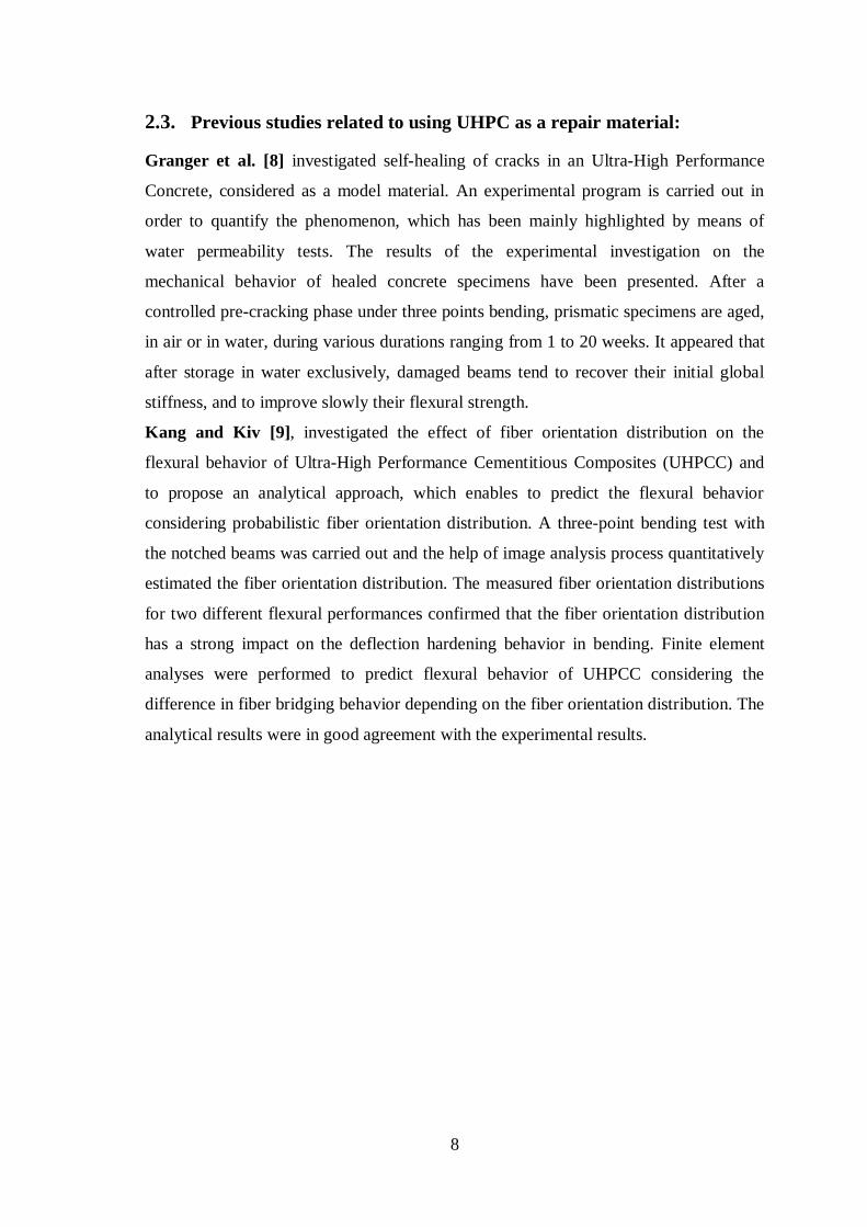
2.3. Previous studies related to using UHPC as a repair material:
Granger et al. [8] investigated self-healing of cracks in an Ultra-High Performance
Concrete, considered as a model material. An experimental program is carried out in
order to quantify the phenomenon, which has been mainly highlighted by means of
water permeability tests. The results of the experimental investigation on the
mechanical behavior of healed concrete specimens have been presented. After a
controlled pre-cracking phase under three points bending, prismatic specimens are aged,
in air or in water, during various durations ranging from 1 to 20 weeks. It appeared that
after storage in water exclusively, damaged beams tend to recover their initial global
stiffness, and to improve slowly their flexural strength.
Kang and Kiv [9], investigated the effect of fiber orientation distribution on the
flexural behavior of Ultra-High Performance Cementitious Composites (UHPCC) and
to propose an analytical approach, which enables to predict the flexural behavior
considering probabilistic fiber orientation distribution. A three-point bending test with
the notched beams was carried out and the help of image analysis process quantitatively
estimated the fiber orientation distribution. The measured fiber orientation distributions
for two different flexural performances confirmed that the fiber orientation distribution
has a strong impact on the deflection hardening behavior in bending. Finite element
analyses were performed to predict flexural behavior of UHPCC considering the
difference in fiber bridging behavior depending on the fiber orientation distribution. The
analytical results were in good agreement with the experimental results.
9
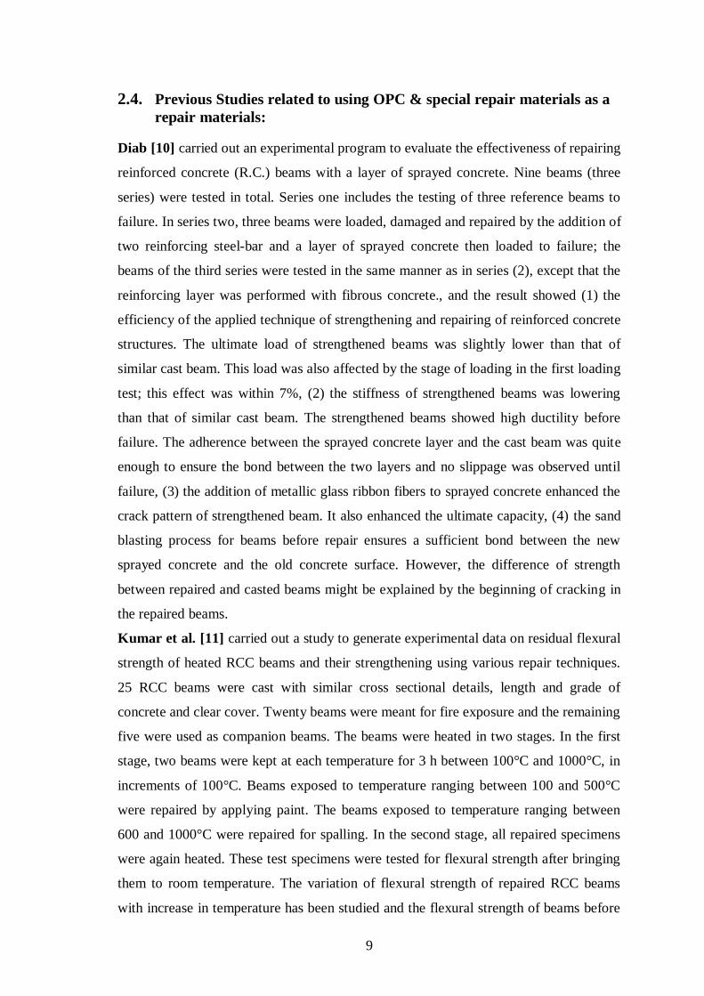
2.4. Previous Studies related to using OPC & special repair materials as a
repair materials:
Diab [10] carried out an experimental program to evaluate the effectiveness of repairing
reinforced concrete (R.C.) beams with a layer of sprayed concrete. Nine beams (three
series) were tested in total. Series one includes the testing of three reference beams to
failure. In series two, three beams were loaded, damaged and repaired by the addition of
two reinforcing steel-bar and a layer of sprayed concrete then loaded to failure; the
beams of the third series were tested in the same manner as in series (2), except that the
reinforcing layer was performed with fibrous concrete., and the result showed (1) the
efficiency of the applied technique of strengthening and repairing of reinforced concrete
structures. The ultimate load of strengthened beams was slightly lower than that of
similar cast beam. This load was also affected by the stage of loading in the first loading
test; this effect was within 7%, (2) the stiffness of strengthened beams was lowering
than that of similar cast beam. The strengthened beams showed high ductility before
failure. The adherence between the sprayed concrete layer and the cast beam was quite
enough to ensure the bond between the two layers and no slippage was observed until
failure, (3) the addition of metallic glass ribbon fibers to sprayed concrete enhanced the
crack pattern of strengthened beam. It also enhanced the ultimate capacity, (4) the sand
blasting process for beams before repair ensures a sufficient bond between the new
sprayed concrete and the old concrete surface. However, the difference of strength
between repaired and casted beams might be explained by the beginning of cracking in
the repaired beams.
Kumar et al. [11] carried out a study to generate experimental data on residual flexural
strength of heated RCC beams and their strengthening using various repair techniques.
25 RCC beams were cast with similar cross sectional details, length and grade of
concrete and clear cover. Twenty beams were meant for fire exposure and the remaining
five were used as companion beams. The beams were heated in two stages. In the first
stage, two beams were kept at each temperature for 3 h between 100°C and 1000°C, in
increments of 100°C. Beams exposed to temperature ranging between 100 and 500°C
were repaired by applying paint. The beams exposed to temperature ranging between
600 and 1000°C were repaired for spalling. In the second stage, all repaired specimens
were again heated. These test specimens were tested for flexural strength after bringing
them to room temperature. The variation of flexural strength of repaired RCC beams
with increase in temperature has been studied and the flexural strength of beams before

10
and after the repair was compared. The following conclusions have been drawn from
this investigation: (1) the normal-strength concrete could sustain up to 500°C without
any visible distress. (2) The weights of the beams were reduced when heated to higher
temperatures. The loss of water at elevated temperatures contributes to a decrease in
flexural strength.(3) Visible thermal cracks were formed beyond 600°C and they
increased in width at increasing temperatures. Spalling of cover concrete was observed
in beams exposed to 1000°C before repair. Severe spalling of concrete was observed in
the temperature range 700–1000°C, in beams that were heated after repair. (4) The
beams exposed to temperatures between 100 and 500°C failed in flexure. Shear cracks
were predominant and the beams failed in shear beyond 600°C. (5) The residual
strength in the beams between temperatures 100 and 400°C was unclear. The strength
was found to decrease almost linearly beyond 400°C. (6) Increased flexural strength
was observed at temperatures between 100 and 600°C in the case of beams repaired by
applying paint. (7) Unheated, repaired beams exhibited improved flexural strength.
They failed to show the same performance when exposed to 600–1000°C.
Ahmad et. al. [12] presented the results of an experimental investigation on the
strengthening of existing cracked RC members. The proposed technique consists of
applying locally available polymer modified mortar in cracked beams to increase the
load carrying capacity. Six full-scale RC beams were constructed with the same
material using the same mix and water cement ratio. Initially, beams were tested until
the development of cracks with width reached a limiting value of 1mm. The beams were
then repaired with the application of polymer modified mortar technique. After 3 days
of water curing the beams were tested again and loaded until the failure. An
improvement in the load carrying capacity was observed in the beams after the
retrofitting. Results clearly demonstrate the effectiveness of the proposed technique in
repairing the RC members for strengthening the existing structures. On the basis of the
results obtained from this study, RC beams can be strengthened by repairing the
existing flexural and shear cracks with PMM application and this can lead to a
considerable (36%) increase in the load carrying capacity.
Hashemi and Al-Mahaid [13] investigation of the flexural behavior of FRP-
strengthened reinforced concrete beams using cement-based adhesives. It is concluded
that the use of cement-based bonding materials is a promising technique in FRP
applications for structures located in hot regions or in danger of fire. Compared to
CFRP fabric, CFRP textile is more compatible as well as more efficient with cement-
11
based mortar. The ultimate load achieved by using CFRP textile-cement mortar is
around 80% of what was achieved by using CFRP fabric with epoxy adhesive.
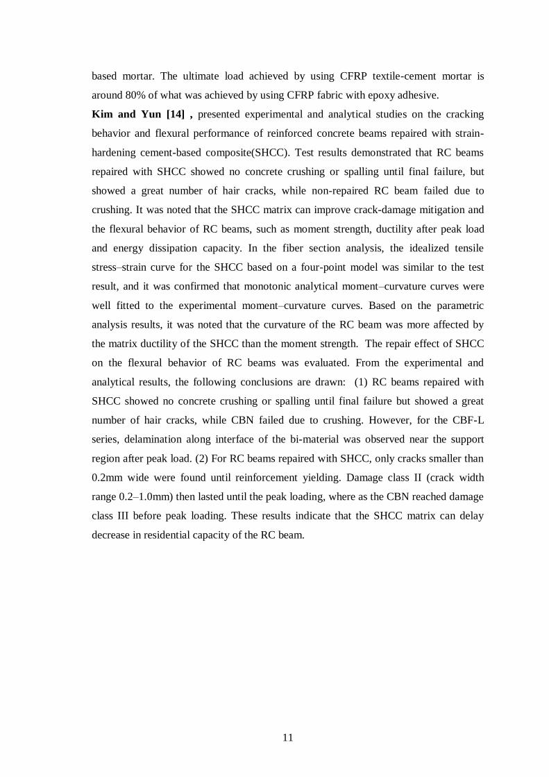
Kim and Yun [14] , presented experimental and analytical studies on the cracking
behavior and flexural performance of reinforced concrete beams repaired with strain-
hardening cement-based composite(SHCC). Test results demonstrated that RC beams
repaired with SHCC showed no concrete crushing or spalling until final failure, but
showed a great number of hair cracks, while non-repaired RC beam failed due to
crushing. It was noted that the SHCC matrix can improve crack-damage mitigation and
the flexural behavior of RC beams, such as moment strength, ductility after peak load
and energy dissipation capacity. In the fiber section analysis, the idealized tensile
stress–strain curve for the SHCC based on a four-point model was similar to the test
result, and it was confirmed that monotonic analytical moment–curvature curves were
well fitted to the experimental moment–curvature curves. Based on the parametric
analysis results, it was noted that the curvature of the RC beam was more affected by
the matrix ductility of the SHCC than the moment strength. The repair effect of SHCC
on the flexural behavior of RC beams was evaluated. From the experimental and
analytical results, the following conclusions are drawn: (1) RC beams repaired with
SHCC showed no concrete crushing or spalling until final failure but showed a great
number of hair cracks, while CBN failed due to crushing. However, for the CBF-L
series, delamination along interface of the bi-material was observed near the support
region after peak load. (2) For RC beams repaired with SHCC, only cracks smaller than
0.2mm wide were found until reinforcement yielding. Damage class II (crack width
range 0.2–1.0mm) then lasted until the peak loading, where as the CBN reached damage
class III before peak loading. These results indicate that the SHCC matrix can delay
decrease in residential capacity of the RC beam.

12
CHAPTER 3 EXPERMENTAL PROGRAM
3.1. Introduction:
The main objective of the executed testing program is to apply the four repair
techniques for each of three stated repair problems on the reinforced concrete beams.
The proposed testing program includes testing of 39 reinforced beams that are to be
designed, constructed, repaired and tested under flexure to achieve the research
objectives. Three of the beam samples are to be tested as control beams, twelve beam
samples are tested for cracking repair, (as shown in Figure 3-2), twelve beam samples
for honeycombing as shown in Figure 3-3, and twelve beams for concrete cover
separation repair as shown in Figure 3-4. The beam dimensions are designed in
accordance with ACI 318-08, preventing shear failure through using ф8mm stirrups
@50mm. The testing program is also summarized in Figure 3-1.

13
Figure 3-1: Testing Program Flow Chart
Tested Concrete Beam specimen
Cracked Beams
UHPFRC
UHPC
OPC
Repair Material
Honeycombing Beams
UHPFRC
UHPC
OPC
Repair Material
Heated Beams
UHPFRC
UHPC
OPC
Repair Material
3 samples
s
3
samples
3
samples
3
samples
3
samples
3
samples
3
samples
3
samples
3
samples
3
samples
3
samples
3
samples
36 sample
Rep
air
ed
By
:
Rep
air
ed
By
:
Rep
air
ed
By
:

14
3.2. Material Properties:
There are many repair materials that are used all over the world for repairing and
strengthening reinforcing concrete structures.
The repair techniques which will be used in this study include: (1) using Ultra High
Performance Concrete, (2) Ultra high performance fiber reinforced concrete, (3)
Ordinary concrete, and (4) special repair material made by a certified manufacture.
3.2.1. UHPC Properties:
UHPC constituent materials in this study include High Strength Portland Cement CEM
I 52.2R. Nesher Cement, Inc. of Israel, which conforms to ASTM CI 50 (2009), quartz
sand and basalt aggregate, manufactures this cement. The nominal size of crushed basalt
ranges from 0.6 to 6.3 mm, while that of quartz sand is in the range of 0.2 to 0.4 mm.
The specific gravity is 2.80 and absorption is 1.48% for basalt. For quartz , the specific
gravity is 2.66 and the absorption is 0.62%. Crushed quartz sand of a maximum size of
150 µm is used as very fine aggregate. The very fine particles have sizes ranging from
0.1 to 10 µm to the gaps between the cement grains, while the larger particles have sizes
ranging from 10 to 150 µm to fill the gaps between the fine aggregate grains resulting in
much denser matrix. Gray silica fume with SiO2 as main chemical component (95%),
which conforms to the requirement of ASTM CI 240-05 (2005) . In addition, a
superplasticizer PLAST_B101P, delivered from YASMO MISR Company of Egypt is
used to ensure suitable workability. The mix design is shown in Table 3-1.
Table 3-1: UHPC composition
The previous materials are used in preparing UHPC, which can achieve a compressive
strength of 120 MPa, and a volume of 1 cubic meter.
Materials Quantity (kg/m3)
Cement CEM I 52.2R 600
Water 180
Silica fume 93
Quartz powder (0.0 - 0.15 mm) 300
Quartz sand (0.15 - 0.4 mm) 315
Basalt aggregate (0.6 – 1.18 mm) 460
Basalt aggregate (2.36 – 6.3 mm) 530
Super plasticizer 18

15
3.2.2. UHPFRC Properties:
UHPFRC constituent materials used in this research include Portland cement which
meets the requirements of ASTMC150 (2009) quartz sand and basalt aggregate. The
nominal size of crushed basalt ranges from 0.6 to 6.3 mm while that of quartz sand is in
the range of 0.2 to 0.4 mm. The specific gravity is 2.8 and absorption is 1.48 % for
basalt. For quartz sand, the specific gravity is 2.66 and the absorption is 0.62 %.
Crushed quartz powder of a maximum sizeof150μm is used as ultra-fine aggregate.
Silica fume, which conforms to the requirements of ASTM C 1240, (2010), is used. In
addition, a super plasticizer is used to ensure suitable workability. Properties of steel
fibers used in the testing program are shown in Table 3-2.
Table 3-2: properties of steel fibers.
Diameter, mm Aspect ratio Yield strength, MPa
0.32 mm 65 1700
The mix design is shown on Table 3-3.
Table 3-3: UHPFRC composition
The previous materials are used in preparing UHPFRC, which can achieve a
compressive strength of 134 MPa, and a volume of 1 cubic meter.
Materials Quantity (kg/m3)
Cement 600
Water 180
Silica fume 15.5% cement wt. 93
Quartz powder 300
Quartz sand (0.2-0.4 mm) 315
Basalt aggregate (0.6-1.18 mm) 460
Basalt aggregate (2.36-6.3 mm) 530
Steel fiber % volume, 65 aspect ratio 0.50
Super plasticizer 19.8

16
3.2.3. OPC Properties:
OPC constituent materials used in this research include Portland cement which meets
the requirements of ASTMC150 (2009), sand and different sizes of aggregate see
Table 3-4. The compressive strength of this matrix is about 25 MPa .The mix design is
shown in table Table 3-4.
Table 3-4: OPC composition
Materials Quantity (kg/m3)
Cement CEM I 52.2R 300
Water 188
Sand 640
Aggregate (Semsem) 320
Aggregate (Adase) 400
Aggregate (Foule) 520
Super plasticizer 18
3.2.4. Special Repair Materials:
In this research, a repair material named BETONREP 250, High Quality Repairing
Mortar manufactured by YASMO MISR Company, was used.
The compressive strength, at 3 days was 220 kg/cm2, and at 7 days was 300 kg/cm
2,
with water ratio is 10 % that is all according to ASTM C-109.
17
3.3. Cracked beams
The application of the repaired techniques is aimed at strengthening the damaged RC
beams to increase load-carrying capacity.
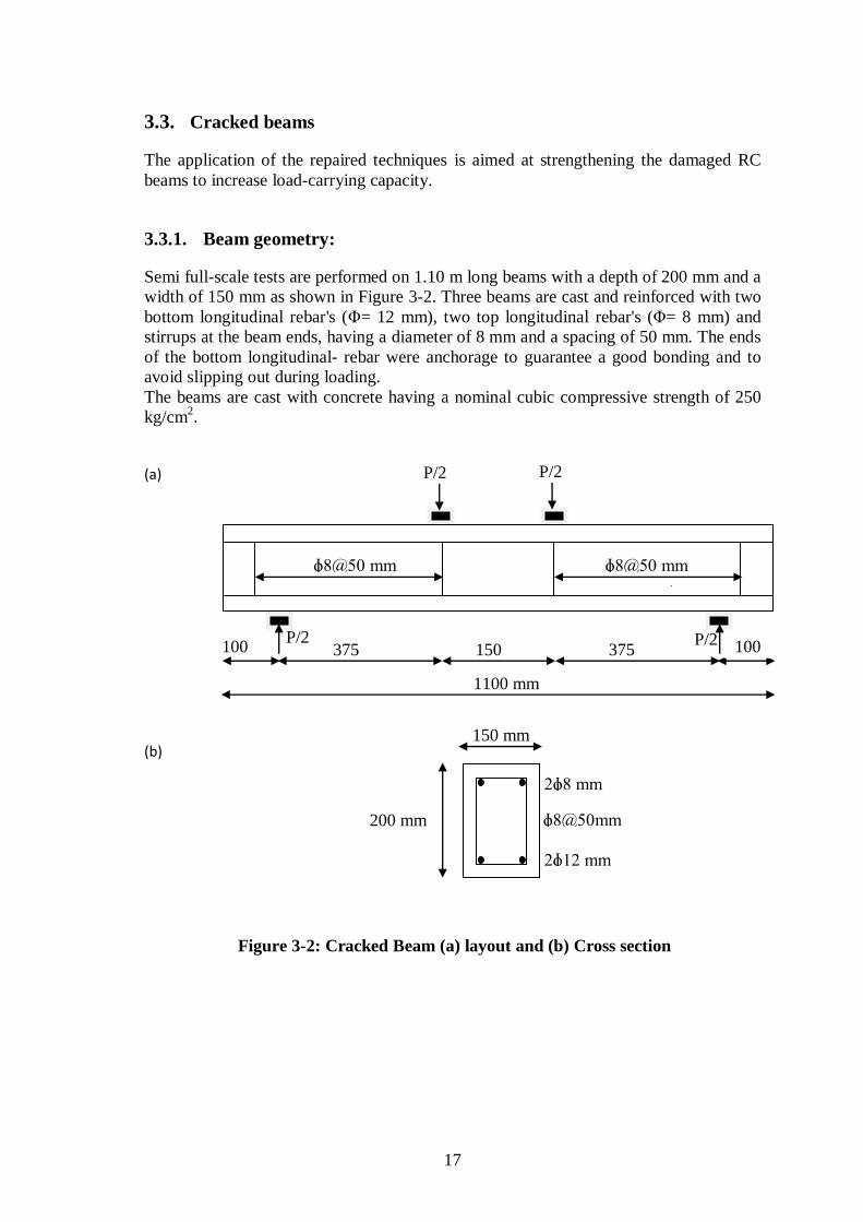
3.3.1. Beam geometry:
Semi full-scale tests are performed on 1.10 m long beams with a depth of 200 mm and a
width of 150 mm as shown in Figure 3-2. Three beams are cast and reinforced with two
bottom longitudinal rebar's (Φ= 12 mm), two top longitudinal rebar's (Φ= 8 mm) and
stirrups at the beam ends, having a diameter of 8 mm and a spacing of 50 mm. The ends
of the bottom longitudinal- rebar were anchorage to guarantee a good bonding and to
avoid slipping out during loading.
The beams are cast with concrete having a nominal cubic compressive strength of 250
kg/cm2.
(a)
(b)
Figure 3-2: Cracked Beam (a) layout and (b) Cross section
150
mm 1100 mm
375
mm
375
mm
ɸ8@50mm ɸ8@50mm
200 mm
150 mm
mm
ɸ8@50mm
2ɸ12mm
2ɸ8mm
100
mm
P/2 P/2 100
mm
P/2 P/2

18
3.3.2. Calculation of flexural capacity of the beam section:
Available data :
Concrete strength fc = 250 kg/cm2 steel yield strength = 4200 kg/cm
2
Width of beam = 15 cm thickness of beam = 20 cm , concrete cover = 2 cm
Bottom steel = 2 Φ12 mm steel stirrup = Φ 8 mm @ 5cm
Analysis of section:
Assume the section is tension controlled
As = 2.27 cm2
From the force diagram , T = C
a =
=
= 3 cm.
c =
, c = 3.35 cm
from strain diagram, Es = ( )
=
( )
= 0.0118 0.005
so assumption of tension controlled section is true.
Φ = 0.90
Mu = ( )( y)
= ( )( )( )(
)= 1.17 ton.m
Mu=(
) 0.375 Pu =
( )
= 6.24 tons.
3.3.3. Number of tested samples:
- 3 samples are used as control beams.
- 3 samples repaired by UHPC.
- 3 samples repaired by UHPFRC.
- 3 samples repaired by OPC.
- 3 samples repaired by specialized repair material.

19
3.3.4. Testing procedure:
The semi full-scale beams are tested under flexure in a four-point loading. The beams
are placed on a 0.90 m span and loaded at two points located at a distance of 0.375 m
from the supports (shear span is equal to 0.95), as shown in Figure 3-2 :
1. Ready the 4-point loading frame and examine all parts of it to make sure it is in
a good condition.
2. Cast all samples and keep it in water for 28-day to achieve full strength.
3. Test the control beams by applying the load and increasing it slowly to reach its
load capacity.
4. Compare the load capacity obtained from the test and the load capacity, which is
obtained from theoretical calculation.
5. Apply the load on the other samples and increase the load slowly to reach the
value of 2/3 Pu = 4.16 ton, where the beam is to fail at serviceability limit state
and crack pattern appears.
6. Draw the crack pattern.
7. Grove the cracks as letter (V) to apply the four repaired materials as (3 samples
for each case).
8. The samples are left for 28 days after repair to achieve the repair material its
strength.
9. Apply the load and increase until failure under flexure.
10. Record the value of the load where the beam has failed.
11. Draw the crack pattern for each case.
12. Compare the values obtained from the control beams with the values obtained
from the repaired samples.
13. Compare the crack patterns of control beams with those for other repaired
beams.
14. Decide on the best suitable repair material.

20
3.4. Honeycombed Beams
The application of the repaired techniques is aimed at strengthening the damaged RC
beams to increase load-carrying capacity.
3.4.1. Beam geometry
Semi full-scale tests are performed on 1.10 m long beams with a depth of 200 mm and a
width of 150 mm, at mid of span in tension zone the section is empty from concrete by
dimension (50mm width, 100mm highest, 150mm depth) as shown in Figure 3-3. Three
beams are cast and reinforced with two bottom longitudinal rebar's (Φ= 12 mm), two
top longitudinal rebar's (Φ= 8 mm) and, at the beam ends, stirrups having a diameter of
8 mm and a spacing of 50 mm. The ends of the bottom longitudinal- rebar were
anchorage to guarantee a good bonding and to avoid slipping out during loading.
The beams are cast with concrete having a nominal cubic compressive strength of 250
kg/cm2.
(a)
(b)
Figure 3-3: Honeycomb Beam (a) layout and (b) Cross section
100 mm
50 mm
100
mm 150
mm 1100 mm
375
mm
375
mm
ɸ8@50mm ɸ8@50mm
200 mm
150mm
mm
ɸ8@50mm
2ɸ12mm
2ɸ8mm
100
mm
P/2 P/2
P/2 P/2
21
3.4.2. Calculation of flexural capacity of the section:
Is same as in section 3.3.2.
3.4.3. Number of tested samples:
- 3 samples are used as control beams.
- 3 samples repaired by UHPC.
- 3 samples repaired by UHPFRC.
- 3 samples repaired by OPC.
- 3 samples repaired by specialized repair material.
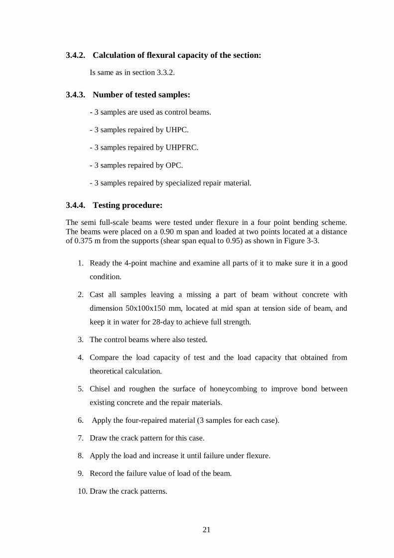
3.4.4. Testing procedure:
The semi full-scale beams were tested under flexure in a four point bending scheme.
The beams were placed on a 0.90 m span and loaded at two points located at a distance
of 0.375 m from the supports (shear span equal to 0.95) as shown in Figure 3-3.
1. Ready the 4-point machine and examine all parts of it to make sure it in a good
condition.
2. Cast all samples leaving a missing a part of beam without concrete with
dimension 50x100x150 mm, located at mid span at tension side of beam, and
keep it in water for 28-day to achieve full strength.
3. The control beams where also tested.
4. Compare the load capacity of test and the load capacity that obtained from
theoretical calculation.
5. Chisel and roughen the surface of honeycombing to improve bond between
existing concrete and the repair materials.
6. Apply the four-repaired material (3 samples for each case).
7. Draw the crack pattern for this case.
8. Apply the load and increase it until failure under flexure.
9. Record the failure value of load of the beam.
10. Draw the crack patterns.

22
11. Compare the values of the control beam with values obtained from each case of
other repaired samples.
12. Compare the crack patterns of control beams with the repaired beams that
obtained from each case.
13. Decide on the best suitable repair material.
3.5. Heated Beams
The application of the repaired techniques is aimed at strengthening the damaged RC
beams to increase load-carrying capacity.
3.5.1. Beam geometry and material properties
The heated beam geometry and its materials propertied as shows in section 3.3.3, except
that the beam length is 0.50 m as shown in Figure 3-4.
(a)
(b)
Figure 3-4: Heated Beam (a) layout and (b) Cross section
3.5.2. Calculation of flexural bearing capacity of the section:
Available data:
150
mm 500 mm
125
mm
125
mm
ɸ8@50mm ɸ8@50mm
200 mm
150mm
mm
ɸ8@50mm
2ɸ12mm
2ɸ8mm
50 mm P/2 P/2 50 mm
P/2 P/2

23
Concrete strength fc = 250 kg/cm2 steel yield strength = 4200 kg/cm
2
Width of beam = 15 cm thickness of beam = 20 cm concrete cover = 2 cm
Bottom steel = 2 Φ12 mm, steel stirrup = Φ 8 mm @ 5cm
Analysis of section:
Assume the section is tension controlled
As = 2.27 cm2
From the force diagram , T = C
a = ( )( )
=
( ) ( )
( )( )( ) = 3 cm.
c =
, c = 3.35 cm
from strain diagram, Es = ( )
=
( )
= 0.0118 0.005
so assumption of tension controlled section is true.
Φ = 0.90
Mu = ( )( y)
= ( )( )( )(
)= 1.17ton.m
Mu=
x 0.125, Pu =
( )
= 18.72 tons.
3.5.3. Number of tested samples:
- 3 samples are used as control beams.
- 3 samples repaired by UHPC.
- 3 samples repaired by UHPFRC.
- 3 samples repaired by OPC.
- 3 samples repaired by specialized repair material.

24
3.5.4. Testing procedure:
The semi full-scale beams were tested under flexure in a four point bending scheme.
The beams were placed on a 0.40 m span and loaded at two points located at a distance
of 0.125 m from the supports (shear span equal to 0.35) as shown in Figure 3-4.
1. Ready the 4-point loading frame and examine all parts of it to make sure it in a
good condition.
2. Cast all samples, and keep it in water for 28-day to achieve full strength.
3. The control beam where also tested.
4. Compare the load capacity of test and the load capacity that obtained from
calculation.
5. Put the samples in electric Oren and heat it to 250C0, for four hours.
6. Pull out the samples and cool them slowly in normal air condition.
7. After the samples are cooled chisel the bottom concrete cover and roughness the
bottom surface for better bond between existing concrete and the repair
materials.
8. Apply the four-repaired material (3 sample for each case).
9. Draw the crack pattern on this situation.
10. Apply the load and increase it until failure in flexure.
11. Record the value of load where the beam has failed.
12. Draw the crack pattern for each case.
13. Compare the value of control beam with values obtained from each case of other
repaired samples.
14. Compare the crack pattern of control beam with repaired beams that are
obtained from each case.
15. Decide on the best solution or the suitable repaired material.

25
CHAPTER 4 REPAIR OF CRACKED BEAMS
4.1. Introduction:
Cracks in concrete are extremely common but often misunderstood. When an owner
sees a crack in a slab or wall, especially if the concrete is relatively new, we assumes
that there is something wrong. This is not always the case. Some types of cracks are
inevitable. The best that a contractor can do about it is to try to control the cracking.
This is done by properly preparing the sub grade, assuring that the concrete is not too
wet, utilizing reinforcement where needed, and by properly placing and spacing crack
control joints and expansion joints. However, sometimes cracks happen in spite of any
precautions taken.
The American Concrete Institute addresses this issue “Evenwiththebestfloordesigns
and proper construction, it is unrealistic to expect crack-free and curl-free floors.
Consequently, every owner should be advised by both the designer and contractor that it
is normal to expect some amount of cracking and curling on every project, and that such
occurrencedoesnotnecessarily reflectadversely oneither theadequacyof the floor’s
design or the quality of its construction.
Excessive cracking is one of the most common causes or damage in concrete structures
and results in huge annual cost to the construction industry. Current design procedures
to control cracking using conventional steel reinforcement are overly simplistic and
often unreliable.
For a concrete structure to be serviceable cracking must be controlled and deflection
must not be excessive. Service load behavior depends primarily on the properties of the
concrete and these are often not known reliably at the design stage. In the design of
concrete structures, it is necessary to check the serviceability of the structure
particularly in the post-cracking range. The effects of several factors, which are difficult
to assess from purely analytical considerations, complicate the behavior in this range.
Of prime importance are the effects of tension stiffening, the random developments of
primary cracks and secondary cracks in regions between the primary cracks and around
the reinforcing bars, and the degree of bond breakdown.
The width of a crack depends on the quantity, orientation and distribution of the
reinforcing steel crossing the crack and the cover to the reinforcement. It also depends
on the bond characteristics between the concrete and the reinforcement bars at and in
the vicinity of the crack. A local breakdown in bond immediately adjacent to a crack
complicates the modeling.
26
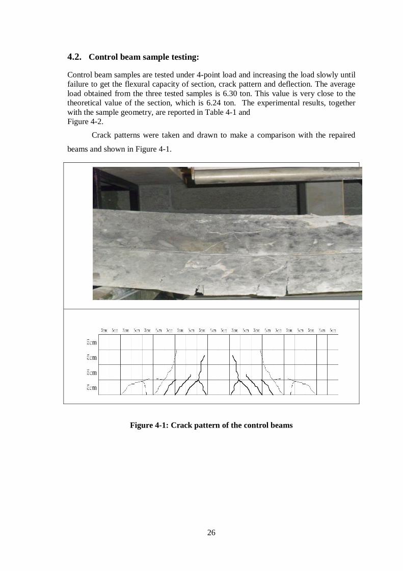
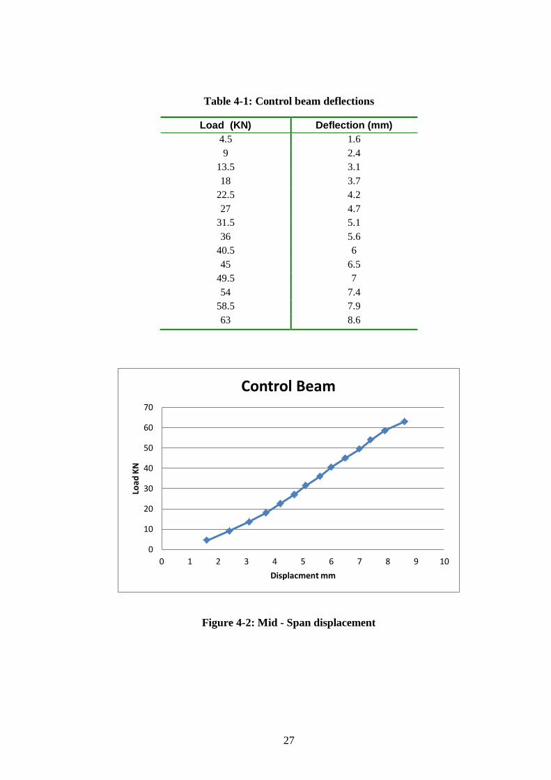
4.2. Control beam sample testing:
Control beam samples are tested under 4-point load and increasing the load slowly until
failure to get the flexural capacity of section, crack pattern and deflection. The average
load obtained from the three tested samples is 6.30 ton. This value is very close to the
theoretical value of the section, which is 6.24 ton. The experimental results, together
with the sample geometry, are reported in Table 4-1 and
Figure 4-2.
Crack patterns were taken and drawn to make a comparison with the repaired
beams and shown in Figure 4-1.
Figure 4-1: Crack pattern of the control beams
27
Table 4-1: Control beam deflections
Load (KN) Deflection (mm)
4.5 1.6
9 2.4
13.5 3.1
18 3.7
22.5 4.2
27 4.7
31.5 5.1
36 5.6
40.5 6
45 6.5
49.5 7
54 7.4
58.5 7.9
63 8.6
Figure 4-2: Mid - Span displacement
0
10
20
30
40
50
60
70
0 1 2 3 4 5 6 7 8 9 10
Load
KN
Displacment mm
Control Beam
28
4.3. Cracked beams after repair:
Before stating the process of repairing techniques on RC beams, the samples are loaded
to 80% of the flexural capacity of the section, (this value is equal to 5.00 tons). The
steps are summarized as follows:
1st Cast the samples and cure it for 28 days.
2nd
Apply 80% of the factored load to the samples to cause cracking as shown in
Figure 4-3:
Figure 4-3: Sample being cracked
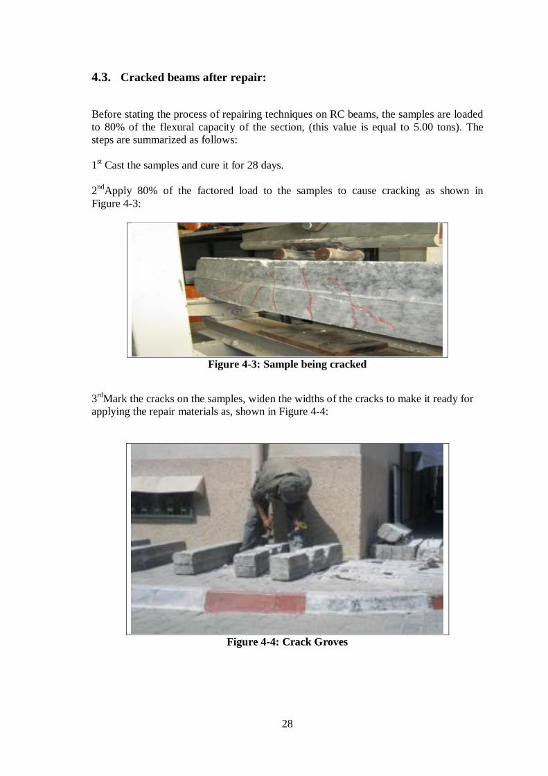
3rd
Mark the cracks on the samples, widen the widths of the cracks to make it ready for
applying the repair materials as, shown in Figure 4-4:
Figure 4-4: Crack Groves

29
4th Wash the samples, shown in Figure 4-5.
Figure 4-5: Cleaning Samples by Water
5thPrepare the samples to receive the four cementious repair materials.
4.3.1. Repairing the cracked beams using UHPC:
Ultra High Performance Concrete (UHPC) is one of the latest developments in concrete
technology. The UHPC refers to materials with a characteristic compressive strength in
excess of 120 MPa. The UHPC is made by using coarse, fine and ultrafine aggregates,
very low amounts of water, silica fume and high amounts of cement. Silica fume is an
ultrafine powder whose particle sizes are 50 to 100 times finer than cement and can fill
up the voids created by the free water in the cement matrix. Chemically, it reacts with
Calcium Hydroxide (CH) to produce additional Calcium silicate Hydrate (CSH). The
reaction between hydrated Portland cement compounds and Silica fume produces a very
dense microstructure and thus improves the bond between the cement and the
aggregates.
The procedure is summarized in the following section:
6thprepare the required material quantity of UHPC that enter in mixing, to be ready for
application, see Figure 4-6:

30
Figure 4-6: Applying UHPC matrix to the Cracked beams
7thCure the samples after applying the UHPC matrix for 7 days.
8thTest the samples repaired by UHPC and record the results, bearing capacity, crack
pattern and deflection. (See Figure 4-7):
Figure 4-7: Cracked beam repaired by UHPC and its Crack Pattern

31
Beams repaired using UHPC were tested under 4-point load and increasing the load
slowly to failure to get the maximum capacity of section, crack pattern and deflection.
The average value obtained from three tested samples is 6.8 ton, and the deflection
values are recorded in Table 4-2 and Figure 4-8.
Table 4-2: Deflection of UHPC repaired samples
Load ( KN) Deflection (mm)
4.5 1.2
9 1.8
13.5 2.325
18 2.775
22.5 3.15
27 3.525
31.5 3.825
36 4.2
40.5 4.5
45 4.875
49.5 5.25
54 5.55
58.5 5.925
63 6.45
67.5 6.9
Figure 4-8: Displacement – load curve for cracked beams repaired using UHPC
0
10
20
30
40
50
60
70
80
0 1 2 3 4 5 6 7 8
Load
KN
Displacment mm
32
4.3.2. Repair of cracked beam by using UHPFRC:
FRP are composed of unidirectional fibers (primarily glass or carbon) in an
environmentally durable epoxy resin. FRPs have desirable engineering properties (e.g.,
high strength and stiffness, low density, long fatigue life, and high resistance to
corrosion) and offer great potential for cost-effective retrofitting of concrete structures.
Among these, continuous fiber-reinforced laminates have been widely used to
strengthen and rehabilitate concrete beams and columns and many researchers have
reported improvements in strength and stiffness of the retrofitted structures. The
continuous FRP fiber-reinforced laminates exhibit relatively small strains at rupture and
behave in a linear manner to rupture. In addition, anchorage is generally needed to
obtain a good bonding between the composites and concrete structures. On the other
hand, the addition of steel fibers have a positive impact on splitting tensile strength and
flexural strength of concrete.
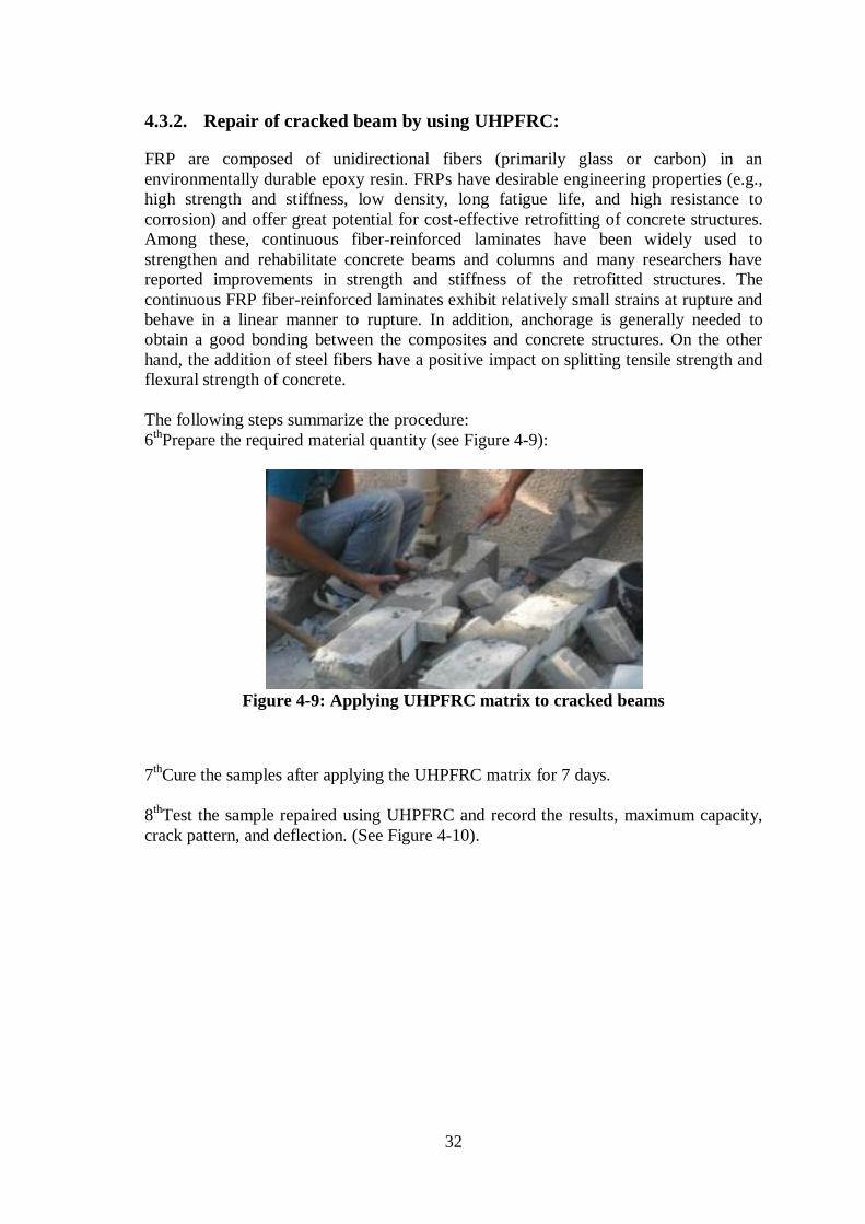
The following steps summarize the procedure:
6thPrepare the required material quantity (see Figure 4-9):
Figure 4-9: Applying UHPFRC matrix to cracked beams
7thCure the samples after applying the UHPFRC matrix for 7 days.
8thTest the sample repaired using UHPFRC and record the results, maximum capacity,
crack pattern, and deflection. (See Figure 4-10).

33
Figure 4-10: Cracking pattern of cracked beams repaired by UHPFRC
Cracked beams repaired using UHPFRC were tested under 4-point load by increasing
the load slowly to be failure to get the maximum capacity of section, crack pattern, and
deflection. The average load value of testing is 7.50 ton, and the deflection values are
recorded in Table 4-3 and Figure 4-11.
Table 4-3: UHPFRC sample Deflections
Load (KN) Deflection (mm)
4.5 0.83
9 1.25
13.5 1.6
18 1.9
22.5 2.2
27 2.5
31.5 2.6
36 3
40.5 3.1
45 3.4
49.5 3.6
54 3.8
58.5 4.1
63 4.5
67.5 5.05
72 5.5
74.997 6.15

34
Figure 4-11: Displacement – load curve for cracked beam repaired by UHPFRC
4.3.3. Repairing cracked beams using OPC:
Concrete as a material has been used for many years to build a wide variety of
structures from houses to bridges. A period of dynamic growth in its use came during
the 1960s because of chronic shortage of housing. It was not until signs of decay started
to appear, only 10 years later, that research on the durability of such concrete structures
was implemented. The beams were repaired using, OPC.
The procedure is summarized as follows:
6thPrepare the required material quantity of OPC (see Figure 4-12)
Figure 4-12: Applying OPC matrix to Cracked beams
0
10
20
30
40
50
60
70
80
0 1 2 3 4 5 6 7
Load
KN
Displacment mm
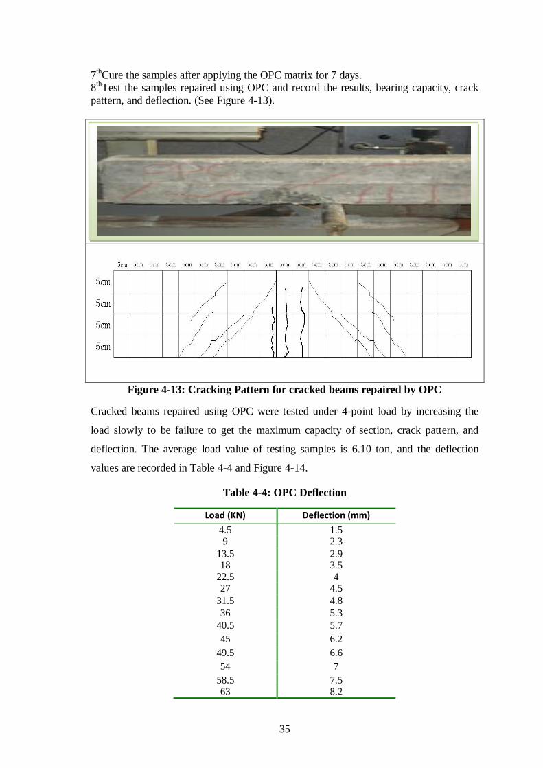
35
7thCure the samples after applying the OPC matrix for 7 days.
8thTest the samples repaired using OPC and record the results, bearing capacity, crack
pattern, and deflection. (See Figure 4-13).
Figure 4-13: Cracking Pattern for cracked beams repaired by OPC
Cracked beams repaired using OPC were tested under 4-point load by increasing the
load slowly to be failure to get the maximum capacity of section, crack pattern, and
deflection. The average load value of testing samples is 6.10 ton, and the deflection
values are recorded in Table 4-4 and Figure 4-14.
Table 4-4: OPC Deflection
Load (KN) Deflection (mm)
4.5 1.5 9 2.3
13.5 2.9 18 3.5
22.5 4
27 4.5
31.5 4.8
36 5.3
40.5 5.7
45 6.2
49.5 6.6
54 7
58.5 7.5 63 8.2

36
Figure 4-14: Displacement – load curve for cracked beam repaired by OPC
4.3.4. Repairing cracked beams using special Repair Material (SRM):
The procedure is summarized as follows:
6th Prepare the required material quantity of SRM (see Figure 4-15):
Figure 4-15: Applying RM matrix to Cracked Beams
7thCure the samples after applying the SRM matrix for 7 days.
8thTest the samples repaired using SRM and record the results, bearing capacity, crack
pattern, and deflection.( See Figure 4-16)
0
10
20
30
40
50
60
70
0 1 2 3 4 5 6 7 8 9
Loa
d K
N
Displacment mm

37
Figure 4-16: Cracking Pattern for cracked beams repaired by SRM
Cracked beams repaired using SRM were tested under 4-point load by increasing the
load slowly to be failure to get the maximum capacity of section, crack pattern, and
deflection. The average load value of testing three samples is 7.00 ton, and the
deflection values are recorded in Table 4-5 and Figure 4-17.
Table 4-5: SRM Deflection
Load (KN) Deflection (mm)
4.5 1
9 1.5
13.5 2
18 2.3
22.5 2.6
27 3
31.5 3.2
36 3.5
40.5 3.8
45 4.1
49.5 4.4
54 4.6
58.5 5
63 5.4
67.5 5.95
69.9975 6.6

38
Figure 4-17: Displacement – load curve for cracked beam repaired by SRM
0
10
20
30
40
50
60
70
80
0 1 2 3 4 5 6 7
Load
KN
Displacment mm

39
4.4. Results and Discussion:
4.4.1. Flexural capacity
Table 4-6 shows that there are differences between the capacities of the repaired beams
and the control ones. This demonstrates that usual repair process that occur to damaged
beam has a significant result on the section and load bearing capacity. It also shows that
the repair of cemetituous materials formed good materials for repair beam cracks.
Comparing the repaired beams with the control ones, it is clear that the repair process
restored the bearing capacity of the section when tested after 1 week after the
application of the repair material, except for the beams which were repaired by OPC
yielded very close results compared to the control beam.
The beams, which were repaired by UHPC achieved flexural strengths 8% larger than
those of the control beams. In addition, beams that were repaired by UHPFRC
developed flexural strength 19 % larger than those of the control beams. On other hand,
beams repaired by OPC had flexural strengths 3.17 % smaller than those of the control
beams. Beams that were repaired by SRM developed flexural strength 11 % larger than
those of the control beams.
Failure of all Beams did not occur in the repair zone but was a sudden explosive
collapse in the compression zone of the beam with no apparent sign of reduced bond.
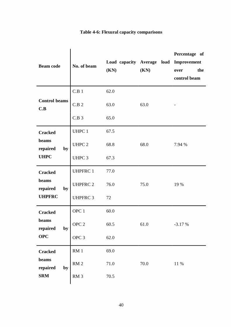
40
Table 4-6: Flexural capacity comparisons
Beam code No. of beam Load capacity
(KN)
Average load
(KN)
Percentage of
Improvement
over the
control beam
Control beams
C.B
C.B 1 62.0
63.0 - C.B 2 63.0
C.B 3 65.0
Cracked
beams
repaired by
UHPC
UHPC 1 67.5
68.0 7.94 % UHPC 2 68.8
UHPC 3 67.3
Cracked
beams
repaired by
UHPFRC
UHPFRC 1 77.0
75.0 19 % UHPFRC 2 76.0
UHPFRC 3 72
Cracked
beams
repaired by
OPC
OPC 1 60.0
61.0 -3.17 % OPC 2 60.5
OPC 3 62.0
Cracked
beams
repaired by
SRM
RM 1 69.0
70.0 11 % RM 2 71.0
RM 3 70.5

41
4.4.2. Mid-Span deflections:
The deflections at mid-span were recorded and plotted against the load as shown in
Figure 4-18. Given that deflection is related to stiffness, it can be stated that the process
of repair has a major effect on stiffness. But it can be noticed that lower deflections
were recorded for the repaired beams when compared with the control ones. The repair
material was applied at the area of highest bending moment, which has got the bending
reinforcement overlapped. Given that the original cracked, concrete was defined prior to
repair, the decrease in deflection of repaired beams shows that the repair process
develop full anchorage between reinforcement bars.
The repaired beams on the other hand showed four broad categories. The first is beams
repaired by UHPC which exhibited stiff behavior with low deflections and
approximately linear load-deflection plots, while decrease deflection of about 73% from
the control beam (See Table 4-7). The second is beams repaired by UHPFRC that
exhibited stiff behavior with low total deflection and approximately linear load-
deflection plots, while decreases the deflection of about 51% from control beam. The
third is beams repaired by OPC which exhibited stiff behavior with low deflections and
approximately linear load-deflection plots, while semi deflection value of control beam.
The fourth is beams repaired by SRM, which exhibited stiff behavior with low
deflections and approximately linear load-deflection plots, while decreases the
deflection of about 63% from control beam.
The curves in Figure 4-18 on the other hand can easily establish the four stages
including the plastic one. This enhanced flexible behavior may be attributed to the
lower modulus of elasticity of the repair material used.
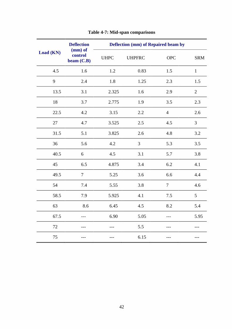
42
Table 4-7: Mid-span comparisons
Load (KN)
Deflection
(mm) of
control
beam (C.B)
Deflection (mm) of Repaired beam by
UHPC UHPFRC OPC SRM
4.5 1.6 1.2 0.83 1.5 1
9 2.4 1.8 1.25 2.3 1.5
13.5 3.1 2.325 1.6 2.9 2
18 3.7 2.775 1.9 3.5 2.3
22.5 4.2 3.15 2.2 4 2.6
27 4.7 3.525 2.5 4.5 3
31.5 5.1 3.825 2.6 4.8 3.2
36 5.6 4.2 3 5.3 3.5
40.5 6 4.5 3.1 5.7 3.8
45 6.5 4.875 3.4 6.2 4.1
49.5 7 5.25 3.6 6.6 4.4
54 7.4 5.55 3.8 7 4.6
58.5 7.9 5.925 4.1 7.5 5
63 8.6 6.45 4.5 8.2 5.4
67.5 --- 6.90 5.05 --- 5.95
72 --- --- 5.5 --- ---
75 --- --- 6.15 --- ---

43
Figure 4-18: Load - Deflection Relationship
0
10
20
30
40
50
60
70
80
0 1 2 3 4 5 6 7 8 9 10
Load
KN
Displacment mm
COMBINATION
SRM
C.B
UHPC
UHPFRC
OPC
44
4.4.3. Crack patterns:
The control beams displayed a crack pattern as shown in Figure 4-19. At low loads,
flexural cracks appeared and propagated at the bottom of the beam within the middle
third of the span. As the load was increased, shear cracks also began to develop between
the loading points. The increased shear force pushed down on the longitudinal steel and
links, and causes the destruction of the bond between concrete and steel. The hooks at
the end caused the beams to behave as a two-hinged arch until the internal stresses
destroyed the surrounding concrete. However, the presence of laps within the test beams
prevented this stage developing fully as the bars, once stripped of their bond, deflect
downward restrained only by the links and, ultimately, break off the surrounding
concrete. Thus, cracks are clearly visible on the underside of the beam, following the
position of the steel.
The repaired beams followed a semi similar cracking pattern, although within the repair
material only nominal cracks were observed. The main cracks were concentrated within
the concrete at areas of high bending moment either side of the repair. Failure was again
due to the breakdown of the bond between the steel and concrete on compression zone.
The reduced cracking in the repaired zone implies that this section suffered less
straining than the adjacent concrete may be due to lack of perfect bond between the
repair material and host concrete.
Improvement of crack pattern for beams repaired by UHPFRC and SRM that refer to
good bonding between the repair materials and old concrete. The crack pattern of beams
repaired by OPC and UHPC are similar cracking pattern of control beam that refers to
less bonding between these materials and old concrete.

45
Crack pattern of control beams
Crack pattern of UHPC beams
Crack pattern of UHPFRC beams
Crack pattern of OPC beams
Crack pattern of SRM beams
Figure 4-19: Crack pattern comparisons

46
CHAPTER 5 REPAIR OF HONEYCOMBED BEAMS
5.1. Introduction:
Reinforced concrete is a combination of concrete (cement and aggregates) and
reinforcing steel. The cement mortar portion of this composite material (approx 25% of
the concrete) acts as a paste or glue that binds aggregates together. When properly
designed and placed these three materials create a unique composite that can be cast
into thousands of different infrastructure applications. In order to have a reinforced
concrete beam, column, slab or wall function properly, the concrete must be properly
consolidated in the forms, i.e. it must completely encapsulate the reinforcement and be
free of voids or "honeycombs". Voids are completely empty or hollow spaces in the
form in which no concrete exists. Honeycombs based on a Portland Cement Association
definition, are voids left in concrete due to failure of the cement mortar to effectively
fill all the spaces between the coarse aggregate particles. Severe honeycombs
(sometimes known as rock pockets) occur when an excessive amount of aggregate is
found without the presence of cement paste. (See Figure 5-1).
Figure 5-1: Honeycomb in a column due to excessive lift depth
47
5.2. Causes of honeycomb:
Primary causes of voids or honeycombs in reinforced concrete:
Rebar Congestion: if rebar is placed too close together or too close to formwork it will
trap the larger pieces of aggregate while the mortar in the mixture may or may not pass
through. Other causes related to rebar congestion include excessive reinforcement
splices that prevent the concrete from properly filling the forms.
Mix Design: Improper mix design can lead to low workability, early stiffening or an
aggregate that is too large to properly consolidate the concrete for a given application.
A good mix design should take in consideration the issues noted for rebar congestion
and lift depth.
Lift Depth: When single concrete placements or "lifts" are too deep, proper vibration
can become very difficult or impossible. Excessive lift depths can also allow too much
free-fall of the concrete that can create a separation of the cement mortar and aggregate
as the aggregate impacts the reinforcing steel when falling through the forms.
Inadequate Vibration: When the concrete is properly vibrated it acts more like a liquid allowing it to better settle in the form, consolidate around the reinforcement and
completely fill the forms. It also helps in releasing any of the air voids in the mix to the
surface. Improper vibration can be related to: o Too small or large a vibrator for the size of the pour and mix design.
o Too low a frequency or amplitude of the vibrator for the size of the pour and
mix design. o Too short or long an insertion time of the vibrator in the concrete in a single
location.
o Too wide of a spacing between each insertion of the vibrator.
o Lift depths too deep to actually vibrate the concrete. o Congested reinforcing that will not allow a standard vibrator to reach all areas
required.
Form Leaks: Leaks in the formwork can allow the cement paste to escape out of the
form leaving behind only unbounded aggregate and rock pockets.

48
5.3. Prevention of honeycomb:
Preventing honeycomb and voids start with attention to concrete mix proportions.
Proper techniques for forming, rebar placement, and concrete placement are important.
5.3.1. Concrete preparation:
Provide enough paste: Concrete not containing enough cementitious material and fine
sand will be prone to segregation and won’tflowwell.Consideraddingablendsandor
additional Portland cement or fly ash to increase the amount of fines. Increasing the
ratio of fine-to-coarse aggregate will increase workability only if 5% to 10% of the sand
passes the No. 100 sieve.
Increase slump: Even with the correct amount of paste, a mix can lack
workability and will not flow into place. To improve flow, increase slump to 15
to 20 cm by adding a water reducer or super plasticizer.
Reduce aggregate size: If closely spaced reinforcement or other obstacles hinder
concrete flow, consider reducing coarse aggregate size below the maximum
allowed by ACI 318-08,“BuildingCodeRequirements for Structural Concrete.”
Such a change requires an overall review of mix proportions.
Control setting rate: Slow placement rates and high ambient and concrete
temperatures can cause concrete to stiffen, reducing its flow ability. Adding a
retarder may help, but retarders do not necessarily prevent slump loss.
5.3.2. Forming and rebar placement:
Review reinforcement details: Closely spaced rebar, insufficient clearance
between the rebar and forms, and closely spaced lap splices all interfere with
concrete flow and vibration. Work with the steel detailer to minimize these
problems.
Provide access to forms: Narrow or tall forms prevent observation and access
during concrete placement. Consider reducing lift heights or using flexible
tremiehose. You may have to cut placing ports into forms containing heavily
reinforced sections.
Build tight form joints: Mortar loss through form joints may cause honeycomb,
particularly with wetter mixes. Tighten or tape form joints as necessary.

49
5.3.3. Concrete placement:
Vibrate properly: Workers must be trained to vibrate concrete correctly to ensure
that it flows around reinforcing steel, embedments, and blockouts.
Ensure flow under blockouts: Build up a head of concrete on one side of small
blockouts, and vibrate the concrete until it appears on the other side. Large
blockouts require concrete to flow many feet laterally, so may need to use pour
pockets beneath these blockouts. Drill holes in the bottom of a blockout to allow
displaced air to escape.
Avoid delays: If the placement is not going as fast as planned, ready mix trucks
may have to wait before discharging material and the concrete will start to
stiffen. You can reduce stiffening by using retarding admixtures, but a better
approach is to alert the concrete producer when unavoidable placing delays
occur.
5.4. Repair Process:
There are several factors to consider when repairing honeycombs and voids:
Honeycomb size and depth.
Access to the repair area.
Rebar details and congestion within the repair area.
Quality assurance (how do you determine actual honeycomb size and prove the
problem is fixed).
Costs from a "repair or replace?" perspective ... which is more cost effective?
These critical items will clearly define the following key steps and sequential order of
repairing the honeycomb, which are:
1. Define the size of the repairs.
2. Define the depth of the repairs.
3. Is shoring required?
4. Select the type of removal.
5. Select the material for repairs.
6. Select the proper placement technique of this material to ensure filling of the
honeycomb and create a composite bond with the substrate.

50
5.4.1. Defining the size and depth:
The actual repair process starts with defining the removal geometry - i.e. size and depth
of the area requiring repair. Methods used can include chipping, sounding and Non
Destructive Testing (NDT) such as Impulse Response or Pulse Echo testing. These tests
measure response times or frequency of a wave or impulse though a concrete section. If
a void exists, the wave or travel time is of course greatly affected. In many cases the
area of repair is going to be larger than what is noticeable to the eye from the surface of
the concrete. This difference is based on several items:
The presence of unseen honeycomb.
The concrete materials around the honeycomb may not be sound and typically
must be removed deep enough to reach a sound substrate.
The final repair shape is normally larger than the rough shape of the actual
honeycomb. Per ACI repair specifications the final surface shape should be
rectilinear in shape vs the rough, multi-shaped honeycomb left after removal of
unsound concrete. Rectilinear can be defined as a combined series of rectangular
and/or square shapes.
Additional removal requirements, in relation the depth of the repair, must be
considered. Typical repair specifications call for a uniform depth throughout the
repair area and where there is any exposed reinforcing steel (50% of the bar
exposed), the concrete should be removed at a minimum of 2 cm behind the bar.
Careful thought must be given to the size, depth and location of the honeycomb as
removal may affect the structural capacity of the element being repaired. If enough
material is missing or is being removed from critical sections of a beam or slab, shoring
should be installed when the honeycomb is detected or prior to removal. This is
especially true with gravity elements such as columns. For example, any chipping or
removal on a column inside the structural core (any section inside the horizontal rebar
ties) will dramatically affect the load carrying capacity. As a rule of thumb, it is better
to err on the side of safety and shore the element.
5.4.2. Removal Techniques:
Removal of the unsound material can be accomplished using hydro demolition
techniques, or typically with 15# chipping hammers. Why use such a small hammer?
When using anything greater than a 30# chipping hammer, the impact forces of the bit
will micro fracture the substrate and damage it. Also in may cases due to the
concentration of rebar in the void, a smaller hammer is easier to accomplish the "dental"
like removal without breaking the bond of the concrete around the rebar outside the
repair area. Chipping is done until a uniform depth and shape is achieved and a
"Fractured Aggregate Profile" is present in the substrate. This chipping profile is
achieved when the aggregate in the concrete is sound and so well bonded that it will
shear in half while being chipped with a 15# hammer. At this point it is clear that the
substrate is sound as the cement paste is well bonded to the aggregate. This is a typical
gauge to determine when sound substrate has been reached.

51
Hydro demolition on the other hand utilizes water pressure up to 50,000 psi to literally
explode the cement in order to remove it. This is advantageous in situations where the
concentration of rebar is so high that it is impossible to remove the concrete with a
chipping gun. It also requires a water collection process due to the volumes of water
required which can be difficult in some environments.
The last step of surface preparation requires that the concrete substrate has an "open
pore structure". During chipping or Hydro demolition, the pores of the concrete have
been impacted and filled with concrete dust and slurry. Removing this is imperative as
the bond between the repair material and substrate can only be achieved by forcing the
repair material into these pores. The concrete can be properly prepared by abrasive
blasting or high pressure water after demolition.
5.4.3. Repair Materials and placement techniques:
Now that the size and depth of the repairs are known, the next step is to determine the
optimum repair material and the best technique for placing it into the honeycomb. For
most honeycomb and voids repairs, the Form and Pump Technique is the best choice to
fill the repair area and ensure a good bond to the existing concrete. Form & Pump, as
the name suggests, pumps the repair material into a closed form. This guarantees two
key requirements noted above. One is making certain that the repair material has
entirely filled the formwork and is consolidated around all rebar. The second relates to
the fact that once the form is full and all air voids removed, it is pressurized. This
assures that the repair material has been literally driven into the open pores of the
existing prepared concrete. This will achieve a bond sufficient to make the two
materials act as one. Use of vent tubes and bleed locations in a Form & Pump repair
operation are important in order to make sure that material is reaching all the sections of
the repair area. Selection of repair material must consider the required flow ability and
aggregate size for void size, shape and rebar clearances. For smaller, more minor
honeycombs or voids, a Form and Cast in Place placement technique and vibration may
be an option for a repair method.
5.5. Control beam testing:
Control beam samples are tested under 4-point load and increasing the load
slowly until failure to get the flexural capacity of section, crack pattern, and deflection.
The average load obtained from the three tested samples is 6.30 ton. This value is very
close to the theoretical value of the section is 6.24 ton. The experimental results,
together with the specimen geometries, are reported in Figure 5-3 and Table 5-1.
Crack pattern were taken and drawn to make a comparison with those of the
repaired beams (see Figure 5-2).

52
Figure 5-2: Crack pattern of control beams
Table 5-1: Control Beam Deflections
load (KN) Deflection (mm)
4.5 1.6
9 2.4
13.5 3.1
18 3.7
22.5 4.2
27 4.7
31.5 5.1
36 5.6
40.5 6
45 6.5
49.5 7
54 7.4
58.5 7.9
63 8.6

53
Figure 5-3: Mid-span Displacement
5.6. Testing of Repaired Honeycombed Beams:
Before start the repairing technique on RC beams, we prepare and cast samples with
missing part of concrete at the middle of the span on the tension side of the beam, to
simulate the honeycomb. They steps are summarized below:
1st Cast the samples and cure them for 28 days.
2nd
Clean the samples after curing time to be ready for applying a cementiouion
material, as shown in Figure 5-4:
Figure 5-4: Cleaning the honeycomb hamples
0
10
20
30
40
50
60
70
0 1 2 3 4 5 6 7 8 9 10
Load
KN
Displacment mm

54
3rd
Chip the honeycomb area to make a good bond with the repair material. This step
appears in Figure 5-5:
Figure 5-5: Hand Blasting Honeycomb Area
4th Wash the samples after chipping process to clean the sample from any loose
aggregate see Figure 5-6.
Figure 5-6: chipping the sample by water
5th Prepare the samples to receive the four cementious repair materials.

55
5.6.1. Repair of Honeycombed beams using UHPC:
6th Prepare the required amount of UHPC, see Figure 5-7.
Figure 5-7: Applying UHPC matrix on Honeycombed beams
7th Cure the samples after applying the UHPC matrix for 7 days.
8th Test the samples and record the results including, flexural capacity, crack pattern,
and deflection. See Figure 5-8:
Figure 5-8: Honeycombed beam repaired, and its crack pattern

56
Beams repaired by UHPC were tested under 4-point load and increasing the load slowly
until failure to get the maximum capacity of the section, crack pattern, and deflection.
The average value obtained from three tested samples is 7.50 ton, and the deflection
values are recorded in Table 5-2 and Figure 5-9.
Table 5-2: deflection of repaired beams by UHPC
Load ( KN) Deflection (mm)
4.5 1.35
9 2.4
13.5 2.6
18 3.2
22.5 3.6
27 4
31.5 4.4
36 4.8
40.5 5.2
45 5.6
49.5 6
54 6.4
58.5 6.8
63 7.4
67.5 7.9
72 8.4
76.5 8.8
Figure 5-9: Displacement – load curve for honeycombed beams repaired by UHPC
0
10
20
30
40
50
60
70
80
90
0 1 2 3 4 5 6 7 8 9 10
Load
KN
Displacment mm

57
5.6.2. Repair a Honeycombed beams using UHPFRC:
6th Prepare the required amount of UHPFRC, See Figure 5-10.
Figure 5-10: Applying UHPFRC matrix to Honeycombed beams
7th Cure the samples after applying the UHPFRC matrix for 7 days.
8th Test the sample repaired and record the results including, flexural capacity, crack
pattern, and deflection. See Figure 5-11.
Figure 5-11: Honeycombed beams repaired, and its crack pattern
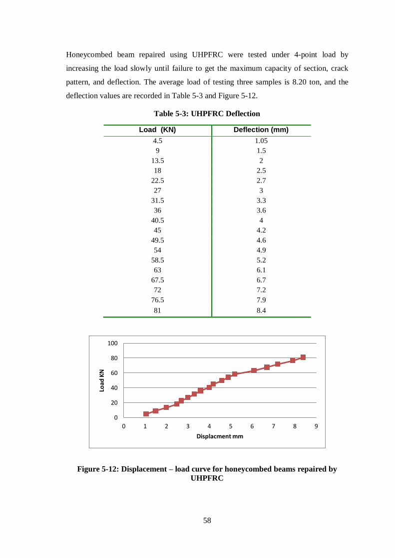
58
Honeycombed beam repaired using UHPFRC were tested under 4-point load by
increasing the load slowly until failure to get the maximum capacity of section, crack
pattern, and deflection. The average load of testing three samples is 8.20 ton, and the
deflection values are recorded in Table 5-3 and Figure 5-12.
Table 5-3: UHPFRC Deflection
Load (KN) Deflection (mm)
4.5 1.05
9 1.5
13.5 2
18 2.5
22.5 2.7
27 3
31.5 3.3
36 3.6
40.5 4
45 4.2
49.5 4.6
54 4.9
58.5 5.2
63 6.1
67.5 6.7
72 7.2
76.5 7.9
81 8.4
Figure 5-12: Displacement – load curve for honeycombed beams repaired by
UHPFRC
0
20
40
60
80
100
0 1 2 3 4 5 6 7 8 9
Load
KN
Displacment mm
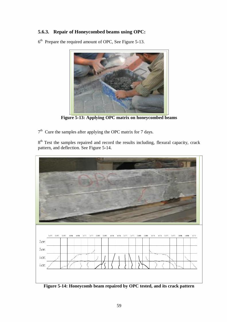
59
5.6.3. Repair of Honeycombed beams using OPC:
6th Prepare the required amount of OPC, See Figure 5-13.
Figure 5-13: Applying OPC matrix on honeycombed beams
7th Cure the samples after applying the OPC matrix for 7 days.
8th Test the samples repaired and record the results including, flexural capacity, crack
pattern, and deflection. See Figure 5-14.
Figure 5-14: Honeycomb beam repaired by OPC tested, and its crack pattern

60
Honeycomb beams repaired using OPC were tested under 4-point load by increasing the
load slowly until failure to get the maximum capacity of section, crack pattern, and
deflection. The average load of testing three samples is 6.45 ton, and the deflection
values are recorded in Table 5-4 and Figure 5-15.
Table 5-4: OPC Deflection
Load (KN) Deflection (mm)
4.5 1.65
9 2.5
13.5 3.2
18 3.85
22.5 4.35
27 4.85
31.5 5.3
36 5.8
40.5 6.2
45 6.7
49.5 7.2
54 7.65
58.5 8.15
63 8.9
Figure 5-15: Displacement – load curve for Honeycombed beam repaired by OPC
0
10
20
30
40
50
60
70
0 1 2 3 4 5 6 7 8 9 10
Load
KN
Displacment mm

61
5.6.4. Repair of Honeycombed beams using Special Repair Material:
6th Prepare the required amount of SRM, See Figure 5-16.
Figure 5-16: Applying RM matrix on Honeycombed beam
7th Cure the samples after applying the RM matrix for 7 days.
8th Test the samples repaired using RM and record the results, bearing capacity, crack
pattern, and deflection. See Figure 5-17.
Figure 5-17: Honeycomb beams repaired by SRM tested, and its crack pattern
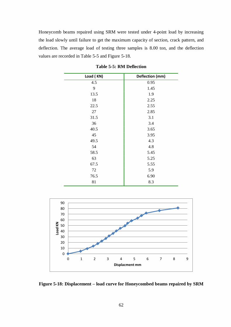
62
Honeycomb beams repaired using SRM were tested under 4-point load by increasing
the load slowly until failure to get the maximum capacity of section, crack pattern, and
deflection. The average load of testing three samples is 8.00 ton, and the deflection
values are recorded in Table 5-5 and Figure 5-18.
Table 5-5: RM Deflection
Figure 5-18: Displacement – load curve for Honeycombed beams repaired by SRM
0
10
20
30
40
50
60
70
80
90
0 1 2 3 4 5 6 7 8 9
Load
KN
Displacment mm
Load ( KN) Deflection (mm)
4.5 0.95
9 1.45
13.5 1.9
18 2.25
22.5 2.55
27 2.85
31.5 3.1
36 3.4
40.5 3.65
45 3.95
49.5 4.3
54 4.8
58.5 5.45
63 5.25
67.5 5.55
72 5.9
76.5 6.90
81 8.3

63
5.7. Results and Discussion:
In the following subsections the results are elaborately discussed.
5.7.1. Flexural capacity:
Table 5-6 shows that there is a significant difference between the repaired beams and
the control beams. This demonstrates that repair process has a significant impact on the
results of the section and load bearing capacity. It also shows that the repaired
cemetituous materials thus formed a good material for repair beam honeycomb.
Comparing the repaired beams with the control ones, it is clear that the repair process
developed the flexural capacity of the section when tested 1 week after the application
of the repair material, except for the beams repaired by OPC, the outcome very close to
the control beam.
This shows that there is difference between the outcome results of used repair materials.
The beams which were repaired by UHPC developed the flexure capacity of the section
about 19%, beams was repaired by UHPFRC develop the bearing capacity about 30%,
beams was repaired by OPC its results is closed to control beam with improvement
about 1.5%, and beams was repaired by SRM develop the bearing capacity about 27%
as shown in Table 5-6. Noted that the outcome results of beams repaired by UHPFRC
and SRM, are almost closed together.
The significant improvement in flexural capacity of the section that occur, due to good
bonding between the repair materials was used and steel reinforcement of it.
The failure of all beams did not occur in the repair zone but was a sudden explosive
collapse in the compression zone of the beam with no apparent sign of reduced bond.

64
Table 5-6: Flexural capacity comparisons
Beam code No. of beam Bearing of
Capacity (KN)
Average
Bearing (KN)
Percentage of
Improvement
over the
control beam
Control beam
(C.B)
C.B 1 62
63 1 C.B 2 63
C.B 3 65
Honeycomb
beam repaired
by (UHPC)
UHPC 1 76
75 1.19 UHPC 2 77
UHPC 3 73
Honeycomb
beam repaired
by (UHPFRC)
UHPFRC 1 80
82 1.30 UHPFRC 2 81
UHPFRC 3 85
Honeycomb
beam repaired
by (OPC)
OPC 1 63
64 1.015 OPC 2 64
OPC 3 65
Honeycomb
beam repaired
by (RM)
RM 1 79
80 1.27 RM 2 81
RM 3 80
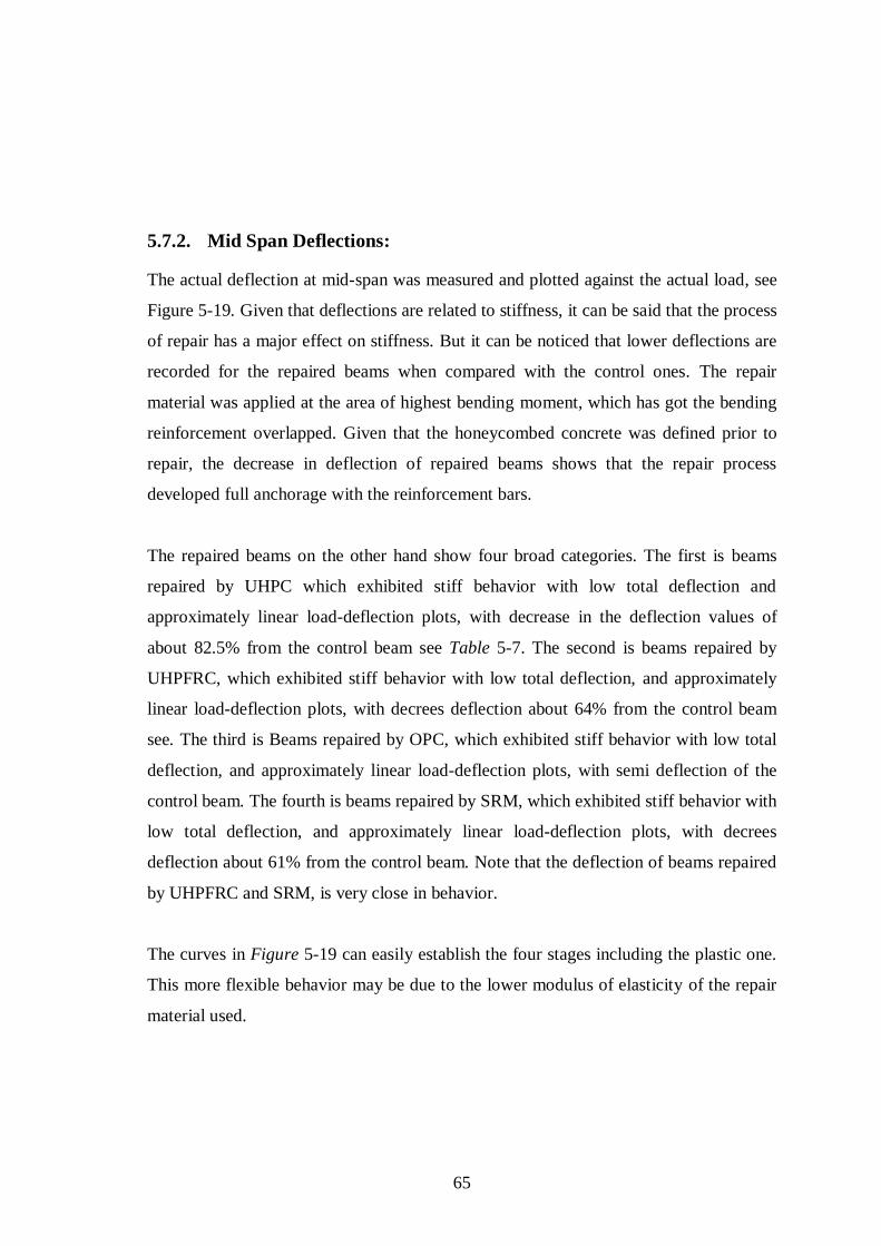
65
5.7.2. Mid Span Deflections:
The actual deflection at mid-span was measured and plotted against the actual load, see
Figure 5-19. Given that deflections are related to stiffness, it can be said that the process
of repair has a major effect on stiffness. But it can be noticed that lower deflections are
recorded for the repaired beams when compared with the control ones. The repair
material was applied at the area of highest bending moment, which has got the bending
reinforcement overlapped. Given that the honeycombed concrete was defined prior to
repair, the decrease in deflection of repaired beams shows that the repair process
developed full anchorage with the reinforcement bars.
The repaired beams on the other hand show four broad categories. The first is beams
repaired by UHPC which exhibited stiff behavior with low total deflection and
approximately linear load-deflection plots, with decrease in the deflection values of
about 82.5% from the control beam see Table 5-7. The second is beams repaired by
UHPFRC, which exhibited stiff behavior with low total deflection, and approximately
linear load-deflection plots, with decrees deflection about 64% from the control beam
see. The third is Beams repaired by OPC, which exhibited stiff behavior with low total
deflection, and approximately linear load-deflection plots, with semi deflection of the
control beam. The fourth is beams repaired by SRM, which exhibited stiff behavior with
low total deflection, and approximately linear load-deflection plots, with decrees
deflection about 61% from the control beam. Note that the deflection of beams repaired
by UHPFRC and SRM, is very close in behavior.
The curves in Figure 5-19 can easily establish the four stages including the plastic one.
This more flexible behavior may be due to the lower modulus of elasticity of the repair
material used.
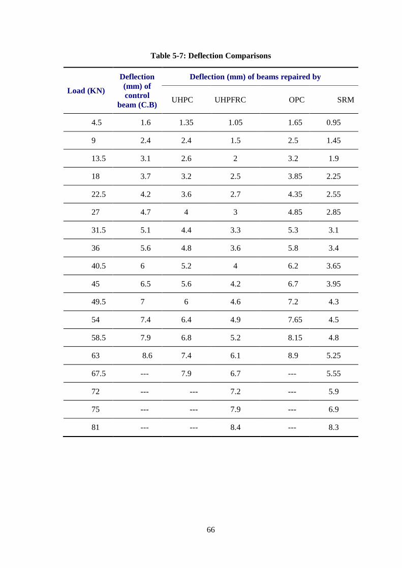
66
Table 5-7: Deflection Comparisons
Load (KN)
Deflection
(mm) of
control
beam (C.B)
Deflection (mm) of beams repaired by
UHPC UHPFRC OPC SRM
4.5 1.6 1.35 1.05 1.65 0.95
9 2.4 2.4 1.5 2.5 1.45
13.5 3.1 2.6 2 3.2 1.9
18 3.7 3.2 2.5 3.85 2.25
22.5 4.2 3.6 2.7 4.35 2.55
27 4.7 4 3 4.85 2.85
31.5 5.1 4.4 3.3 5.3 3.1
36 5.6 4.8 3.6 5.8 3.4
40.5 6 5.2 4 6.2 3.65
45 6.5 5.6 4.2 6.7 3.95
49.5 7 6 4.6 7.2 4.3
54 7.4 6.4 4.9 7.65 4.5
58.5 7.9 6.8 5.2 8.15 4.8
63 8.6 7.4 6.1 8.9 5.25
67.5 --- 7.9 6.7 --- 5.55
72 --- --- 7.2 --- 5.9
75 --- --- 7.9 --- 6.9
81 --- --- 8.4 --- 8.3
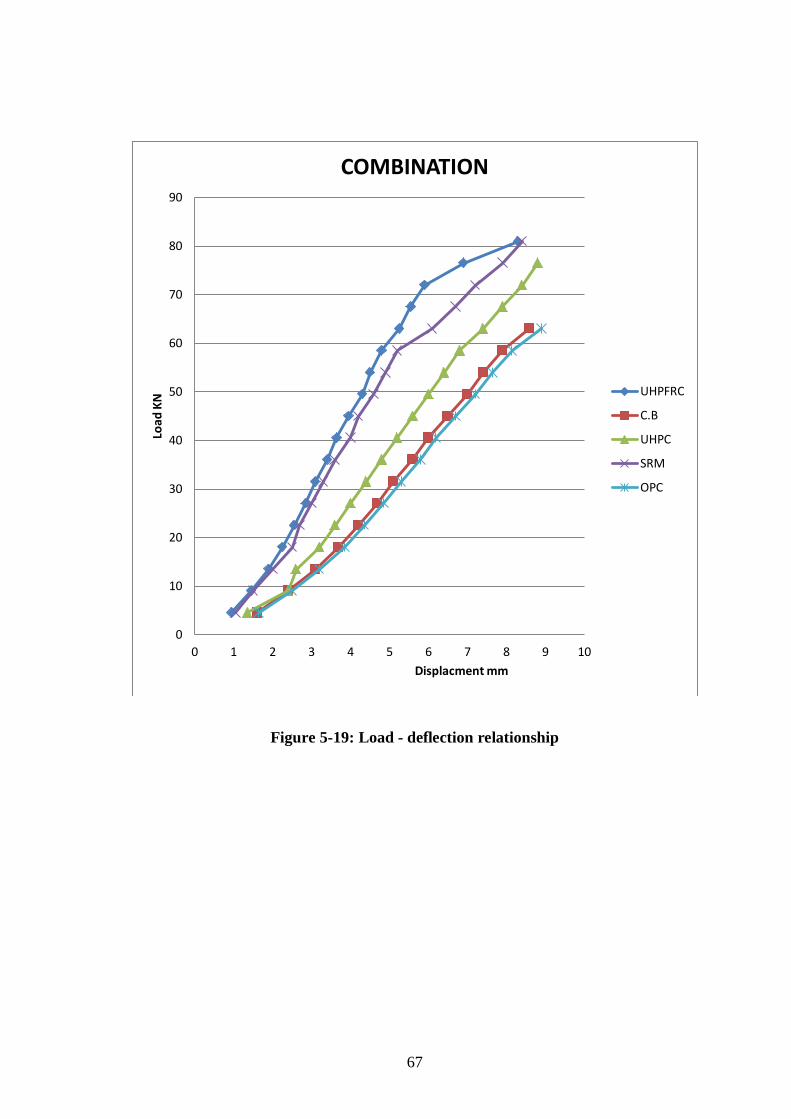
67
Figure 5-19: Load - deflection relationship
0
10
20
30
40
50
60
70
80
90
0 1 2 3 4 5 6 7 8 9 10
Load
KN
Displacment mm
COMBINATION
UHPFRC
C.B
UHPC
SRM
OPC

68
5.7.3. Crack patterns:
The control beams displayed the crack pattern as shown in Figure 5-20. At low loads,
flexural cracks appeared and propagated at the bottom of the beam within the middle
third area of the greatest moment. As the load was increased shear cracks also began to
develop between the loading points. The increased shear force pushes down on the
longitudinal steel and links, and causes the destruction of the bond between concrete
and steel. The hooks at the end cause the beam to behave as a two hinged arch until the
internal stresses destroy the surrounding concrete. However, the presence of laps within
the test beams prevented this stage developing fully as the bars, once stripped of their
bond, deflect downward restrained only by the links and, ultimately, break off the
surrounding concrete. Thus, cracks are clearly visible on the underside of the beam,
following the position of the steel.
The repaired beams followed a semi similar cracking pattern as shown in Figure 5-20 ,
although within the repair material only nominal cracks were observed. The main cracks
were concentrated within the concrete at areas of high bending moment either side of
the repair. Failure was again due to the breakdown of the bond between the steel and
concrete on compression zone. The reduced cracking in the repaired zone implies that
this section suffered less straining than the adjacent concrete may be due to lack of
perfect bond between the repair material and host concrete.
There is a significant improvement in crack patterns for beam repaired by UHPFRC and
SRM which good bonding between the repair materials and the old concrete see
Figure 5-20, while the crack patterns of beams repaired by OPC and UHPC are similar
to cracking pattern of the control beam which shows less bonding between these
materials and the old concrete.

69
Crack pattern of control beams
Crack pattern of UHPC beams
Crack pattern of UHPFRC beams
Crack pattern of OPC beams
Crack pattern of SRM beams
Figure 5-20: Crack pattern comparisons

70
CHAPTER 6 REPAIRED OF HEATED BEAMS
6.1. Introduction:
Concrete spalling is usually caused by corrosion of the steel reinforcement bars
embedded in the concrete matrix, but can be caused by other ferrous elements either
fully or partially embedded in the structure. Steel frame window systems, handrails,
structural I-beams, metal pipes and conduits are among the most common of the
damage causing building components. Corrosion of the reinforcement steel however, is
by far the most common cause of spalling and splitting in older concrete structures.
Explosive spalling occurs when concrete is exposed to fire. It results in loss of section
and reduction in the load bearing capacity. Although spalling has occurred frequently in
buildings, it is the recent examples in tunnel fires that have highlighted the problem in
thepublic’smind.Solvingofthespalling problem is now a primary requirement in any
new tunnel design. Generally explosive spalling is more likely the higher the rate of
heating, the stronger the concrete, the higher the moisture level and the larger the
imposed compressive load. It occurs during the first 7-20 minutes of a fire when the
concrete temperatures are only in the region of 150-300Co. In this case, the heating rate
is a prime influence.
The most recent theories of the causes of explosive spalling indicate that two factors
play a crucial role, namely, the buildup of (a) pore pressure and (b) thermal stresses in
the concrete when exposed to a rapidly increasing temperature.
In this study the fire problem was simulate by exposing the beam samples for elevated
temperature in an electric oven at 250 Co for four hours.
6.2. Definition of Spalling:
Spallin, is defined as the violent or non-violent breaking off layers or pieces of concrete
from the surface of a structural element when it is exposed to high and rapidly rising
temperatures as experienced in fires. There are four types of spalling: explosive,
surface, aggregate and corner spalling. The most important of these is explosive
spalling, which occurs violently and results in serious loss of material.
6.3. Effect and consequence of explosive saplling:
Explosive spalling can take place as a single explosion or a series of explosions, each
removing a thin layer of concrete ranging from 100 mm to 300 mm in length and 15mm

71
to 20mm in depth, capable of causing physical damage on impact. In many cases,
explosive spalling is restricted to the unreinforced part of the section and usually does
not proceed beyond a reinforcing layer (e.g. mesh reinforcement in a slab, or a cage of
bars and links in a beam or a column).
Explosive spalling may, however, result in a sudden and complete failure of the
concrete member to sustain its load-bearing function because of significant loss of
section. Explosive spalling can also blow holes in concrete partitions thus facilitating
the spread of fire and underminingthepartition’s“integrity”.
6.4. Factors Influencing Saplling:
BS 8110:Part 2:1985 states that “rapid rates of heating, large compressive stresses or
high moisture contents (over 5% by volume or 2% to 3% by mass of dense concrete)
can lead to spalling of concrete cover at elevated temperatures, particularly for
thicknessesexceeding40mmto50mm.”
In fact, a large number of factors influence explosive spalling of concrete. These are
described as follows:
1. Heating rate.
2. Temperature level during the explosion.
3. Heating profile.
4. Section size.
5. Section shape.
6. Moisture content.
7. Water curing.
8. Pore pressures.
9. Permeability of the concrete and mean pore radius.
10. Concrete age.
11. Concrete strength, mix and quality.
12. Compressive stress and restraint.
13. Type of aggregate.
14. Aggregate size.
15. Thermal expansion.
16. Cracking.
17. Reinforcement.
18. Cover to reinforcement.
19. Supplementary reinforcement.
20. Steel fibres.
21. Polypropylene fibres.
22. Air-entrainment.

72
6.5. Control beam testing:
Control beam samples are tested under 4-point load and increasing the load
slowly until failure to get the flexural capacity of section, crack pattern, and deflection.
The average load obtained from the three tested samples after heating is 13.50 ton. This
value is about 72% of the theoretical value of the section, which is 18.76 ton. The
experimental results, together with the sample geometry, are reported in Table 6-1 and
Figure 6-2. Crack patterns were taken and drawn to make a comparison with the
repaired beams and shown in Figure 6-1.
Figure 6-1: Crack Pattern of Control Beams
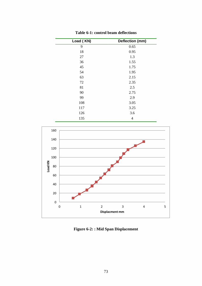
73
Table 6-1: control beam deflections
Load ( KN) Deflection (mm)
9 0.65
18 0.95
27 1.3
36 1.55
45 1.75
54 1.95
63 2.15
72 2.35
81 2.5
90 2.75
99 2.9
108 3.05
117 3.25
126 3.6
135 4
Figure 6-2: : Mid Span Displacement
0
20
40
60
80
100
120
140
160
0 1 2 3 4 5
Load
KN
Displacment mm

74
6.6. Heated beams after repair:
Before stating the presses of repairing techniques on RC beam, sample was casted in
suitable dimensions to suit the furnace dimensions. The steps are summarized here:
1st Cast the samples and cure it for 28 days.
2nd
Heat the samples in a furnace with at 250 Co for four hours, as shown in Figure 6-3.
Figure 6-3: Beam Samples Heated
3rd
Remove the samples form the furnace and cool it in normal conditions without
spreading water on it, as shown in Figure 6-4:
Figure 6-4: Heated beam get cooled

75
4th Chip the concrete cover of the samples and roughen the surface to ensure a good
bond with the repair materials, as shown in Figure 6-5.
Figure 6-5: chip the concrete cover of the heated samples
5th Wash the samples, as shown in Figure 6-6.
Figure 6-6: Cleaning the samples by Water
6th Prepare the samples to receive the four cementious repair materials.

76
6.6.1. Repairing the heated beams using UHPC:
The procedure is summarized in the following section:
7th Prepare the required material quantity of UHPC for application, see Figure 6-7:
Figure 6-7: Applying UHPC matrix to the heated beams
8th Cure the samples after applying the UHPC matrix for 7 days.
9th Test the samples by UHPC and record the results, flexural capacity, crack pattern,
and deflection. (See Figure 6-8):
Figure 6-8: Heated beams repaired by UHPC tested , and its crack pattern

77
Beams repaired using UHPC were tested under 4-point load and increasing the
load slowly to be failure to get the maximum capacity of section, crack pattern, and
deflection. The average value obtained from three tested samples is 13.70 ton, and the
deflection values are recorded on Table 6-2 and Figure 6-9.
Table 6-2: Deflection of UHPC Repaired Samples
Load (KN) Deflection (mm)
9 0.7
18 1
27 1.35
36 1.65
45 1.85
54 2.05
63 2.25
72 2.45
81 2.65
90 2.9
99 3.05
108 3.2
117 3.4
126 3.8
135 4.2
137 4.5
Figure 6-9: Displacement – load curve for heated beams repaired using UHPC
0
20
40
60
80
100
120
140
160
0 1 2 3 4 5
Load
KN
Displacment mm
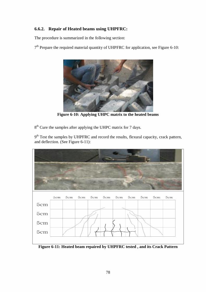
78
6.6.2. Repair of Heated beams using UHPFRC:
The procedure is summarized in the following section:
7th Prepare the required material quantity of UHPFRC for application, see Figure 6-10:
Figure 6-10: Applying UHPC matrix to the heated beams
8th Cure the samples after applying the UHPC matrix for 7 days.
9th Test the samples by UHPFRC and record the results, flexural capacity, crack pattern,
and deflection. (See Figure 6-11):
Figure 6-11: Heated beam repaired by UHPFRC tested , and its Crack Pattern

79
Beams repaired using UHPC were tested under 4-point load and increasing the load
slowly to be failure to get the maximum capacity of section, crack pattern, and
deflection. The average value obtained from three tested samples is 14.40 ton, and the
deflection values are recorded in Table 6-3 and Figure 6-12.
Table 6-3: UHPFRC sample Deflections
load (KN) Deflection (mm)
9 0.7
18 1.05
27 1.45
36 1.7
45 1.9
54 2.15
63 2.35
72 2.6
81 2.75
90 3.05
99 3.2
108 3.35
117 3.6
126 3.95
135 4.4
144 4.95
Figure 6-12: Displacement – load curve for heated beam repaired by UHPFRC
0
20
40
60
80
100
120
140
160
0 1 2 3 4 5 6
Load
KN
Displacment mm

80
6.6.3. Repairing Heated beams using OPC:
The procedure is summarized in the following section:
7th Prepare the required material quantity of OPC for application, see Figure 6-13:
Figure 6-13: Applying OPC matrix to Heated beams
8th Cure the samples after applying the UHPC matrix for 7 days.
9th Test the samples by OPC and record the results, flexural capacity, crack pattern, and
deflection. (See Figure 6-14):
Figure 6-14: Heated beam repaired by OPC tested , and its Crack Pattern

81
Beams repaired using OPC were tested under 4-point load and increasing the load
slowly to be failure to get the maximum capacity of section, crack pattern, and
deflection. The average value obtained from three tested samples is 13.50 ton, and the
deflection values are recorded in Table 6-4 and Figure 6-15.
Table 6-4: OPC Deflection
Load (KN) Deflection (mm)
9 0.65
18 0.95
27 1.3
36 1.55
45 1.75
54 1.95
63 2.15
72 2.35
81 2.5
90 2.75
99 2.9
108 3.05
117 3.25
126 3.6
135 4
Figure 6-15: Displacement – load curve for cracked beam repaired by OPC
0
20
40
60
80
100
120
140
160
0 1 2 3 4 5
Load
KN
Displacment mm

82
6.6.4. Repairing Heated beams using SRM:
The procedure is summarized in the following section:
7th Prepare the required material quantity of SRM for application, see Figure 6-16:
Figure 6-16: Applying RM matrix to Heated beams
8th Cure the samples after applying the RM matrix for 7 days.
9th Test the samples by SRM and record the results, flexural capacity, crack pattern, and
deflection. (See Figure 6-17):
Figure 6-17: Heated beam repaired by SRM tested , and its Crack Pattern

83
Beams repaired using SRM were tested under 4-point load and increasing the load
slowly to be failure to get the maximum capacity of section, crack pattern, and
deflection. The average value obtained from three tested samples is 14.00 ton, and the
deflection values are recorded in Table 6-5 and Figure 6-18.
Table 6-5: SRM Deflection
Load (KN) Deflection (mm)
9 0.7
18 1
27 1.4
36 1.65
45 1.85
54 2.05
63 2.3
72 2.5
81 2.65
90 2.9
99 3.1
108 3.25
117 3.45
126 3.85
135 4.25
140 4.45
Figure 6-18: Displacement – load curve for cracked beam repaired by SRM
0
20
40
60
80
100
120
140
160
0 1 2 3 4 5
Load
KN
Displacment mm

84
6.7. Result and Discussion:
6.7.1. Flexural capacity:
Table 6-6 shows that there are slight improvements between the capacities of the
repaired beams and the control ones. This demonstrates that the repair process has little
effect on the flexural capacity of the section. It also shows that the repaired cemetituous
materials have little effect for repair of the heated beams.
Comparing the repaired beams with the control ones, it is clear that the repair process
did not improve the bearing capacity of the section when tested 1 week after the
application of the repair material, except for the beams repaired by UHPFRC and SRM
which have a slight improvement over the control beam.
The beams, which were repaired by UHPC have achieved flexural strength 1.50 %
higher than those of control beams. In addition, beams that were repaired by UHPFRC
have developed flexural strength 6.66 % higher than those of control beams. Beams
repaired by OPC have no improvement over the control beams. Beams that were
repaired by SRM developed flexural strength 3.70 % higher than those of the control
beams.

85
Table 6-6: Flexural Capacity Comparison
Beam code No. of beam Load capacity
(KN)
Average load
(KN)
Percentage of
Improvement
Control beams
C.B
C.B 1 13.35
13.50 - C.B 2 13.65
C.B 3 13.40
Cracked
beams
repaired by
UHPC
UHPC 1 13.60
13.70 1.50 % UHPC 2 13.80
UHPC 3 13.70
Cracked
beams
repaired by
UHPFRC
UHPFRC 1 14.30
14.40 6.66 % UHPFRC 2 14.40
UHPFRC 3 14.50
Cracked
beams
repaired by
OPC
OPC 1 13.35
13.50 0.00 % OPC 2 13.65
OPC 3 13.40
Cracked
beams
repaired by
RM
RM 1 13.90
14.00 3.70 % RM 2 14.10
RM 3 14.00
86
6.7.2. Mid Span Deflection:
The deflections at mid-span were measured and plotted against the load as shown in
Figure 6-19. Given that deflection is related to stiffness, it can be stated that the process
of repair has a major effect on stiffness But it can be noticed that almost the same case
deflections were recorded for the repaired beams when compared with the control ones.
The repair material was applied at the bottom zone to compensate the concrete cover,
which has got the bending reinforcement overlapped.
The repaired beams on the other hand showed four closed categories. The first is beams
repaired by UHPC which exhibited stiff behavior with low deflections and
approximately linear load-deflection plots, with decrease in deflection of about 5% from
the control beam (See Table 6-7). The second is beams repaired by UHPFRC that
exhibited stiff behavior with low total deflection and approximately linear load-
deflection plots, with decrees in the deflection of about 10% from control beam. The
third is beams repaired by OPC which exhibited stiff behavior with low deflections and
approximately linear load-deflection plots, while semi deflection value of control
beam). The fourth is beams repaired by SRM, which exhibited stiff behavior with low
deflections and approximately linear load-deflection plots, with decrees in the deflection
of about 7% from control beam.
The curves in (Figure 6-19) on the other hand one can easily establish the four stages
including the plastic one. This more flexible behavior may be due to the lower modulus
of elasticity of the repair material used.

87
Table 6-7: Deflection Comparison
Load (KN)
Deflection
(mm) of
control
beam (C.B)
Deflection (mm) of Repaired beam by
UHPC UHPFRC OPC RM
9 0.65 0.7 0.7 0.65 0.7
18 0.95 1 1.05 0.95 1
27 1.3 1.35 1.45 1.3 1.4
36 1.55 1.65 1.7 1.55 1.65
45 1.75 1.85 1.9 1.75 1.85
54 1.95 2.05 2.15 1.95 2.05
63 2.15 2.25 2.35 2.15 2.3
72 2.35 2.45 2.6 2.35 2.5
81 2.5 2.65 2.75 2.5 2.65
90 2.75 2.9 3.05 2.75 2.9
99 2.9 3.05 3.2 2.9 3.1
108 3.05 3.2 3.35 3.05 3.25
117 3.25 3.4 3.6 3.25 3.45
126 3.6 3.8 3.95 3.6 3.85
135 4 4.2 4.4 4 4.25
144 ----- 4.5 4.95 ----- 4.45
153 ----- ----- ----- ---- -----

88
Figure 6-19: Load - Deflection Relationship
0
20
40
60
80
100
120
140
160
0 1 2 3 4 5
Load
KN
Displacment mm
COMBINATION
89
6.7.3. Crack patterns:
The control beams displayed a crack pattern as shown in Figure 6-20. At low loads,
flexural cracks appeared and propagated at the bottom of the beam within the middle
third of the span. As the load was increased, shear cracks also began to develop between
the loading points. The increased shear force pushed down on the longitudinal steel and
links, and cased the destruction of the bond between concrete and steel. The hooks at
the end caused the beams to behave as a two-hinged arch until the internal stresses
destroyed the surrounding concrete. However, the presence of laps within the test beams
prevented this stage developing fully as the bars, once stripped of their bond, deflect
downward restrained only by the links and, ultimately, break off the surrounding
concrete. Thus, cracks are clearly visible on the underside of the beam, following the
position of the steel.
The repaired beams followed a semi similar cracking pattern, although within the repair
material only nominal cracks were observed. The main cracks were concentrated within
the concrete at areas of high bending moment either side of the repair. Failure was again
due to the breakdown of the bond between the steel and concrete in the compression
zone. In addition that appears longitudinal cracks through the boundary between the old
concrete and repaired layer (concrete cover), but its length varies in each case of the
repaired samples.
On case of samples repaired by UHPC and UHPFRC the longitudinal cracks are appear
on the mid third of the span at the maximum flexural zone, but the samples were
repaired by OPC and SRM the longitudinal cracks are appear through the all length of
boundary line. This means that the layer that was added did not achieve satisfactory
results, in terms of happened to her separation from the repaired samples and less
bonding with old concrete.

90
Crack pattern of control beams
Crack pattern of UHPC beams
Crack pattern of UHPFRC beams
Crack pattern of OPC beams
Crack pattern of SRM beams
Figure 6-20: Crack PatternS Comparisons

91
CHAPTER 7 CONCLUSIONS AND RECOMMENDATIONS
7.1. Conclusions:
The load capacity, deflection and crack patterns of RC beams retrofitted with UHPC,
UHPFRC, OPC and SRM were studied experimentally. The study intended to assess the
feasibility of using UHPC, UHPFRC, OPC, and SRM for repair and strengthening of
damaged RC beams. A series of four-point bending tests were carried out on both
damaged and undamaged RC beams in order to evaluate the performance of damaged
RC beams after application of repaired materials and to select the best repair technique
for each of the caused damage.
The tests yielded complete load–deflection curves from which the increase in load
capacity was evaluated. The findings of the experimental study can be summarized as
follows:
1. Comparing the repaired cracked beams with the control ones. It is clear that the
repair process restored the flexural capacities of the sections when tested 1 week
after the application of the repair material, except for the beams which were
repaired using OPC where the outcome is much closer to the control beams.
2. The cracked beams, repaired using UHPC achieved flexural strengths 8 %
higher than control beams. In addition, beams that were repaired using UHPFRC
developed flexural strength 19 % higher than those for the control beams. Beams
repaired using OPC had flexural strengths 3.17 % smaller than those for the
control beams. In addition, beams that were repaired using RM developed
flexural strengths 11 % higher than those for the control beams.
3. The cracked beams repaired using the four repair materials showed
improvement in ductility of compared with the control beams, expect for the
beams which were repaired using OPC, which showed results close to those
obtained from the control beams.
4. The honeycombed beams repaired using UHPC developed flexural capacities
19%, higher than those repaired using UHPFRC developed the bearing
capacities 30%, higher than those repaired using OPC its results is close to the
control beam with improvement of about 1.5%, and beams which were repaired
by SRM developed the bearing capacity about 27%.
92
5. A significant improvement in flexural capacity may be attributed good bonding
between the repair materials and the old concrete. In addition to the higher
performance of the repair materials.
6. The heated were repaired using UHPC have achieved flexural strength 1.50 %
higher than those of the control beams. In addition, beams that were repaired
using UHPFRC developed flexural strengths 6.66 % higher than those of the
control beams. Furthermore, beams repaired using OPC has no improvement
over the control beams. While beams repaired using SRM developed flexural
strengths 3.70 % higher than those of the control beams.
7. The repaired cracked beams on the other hand showed four categories. The first
is beams repaired using UHPC which exhibited stiff behavior with low
deflections and approximately linear load-deflection plots, with 73% decrease in
deflection compared to control beam. The second is beams repaired using
UHPFRC which exhibited stiff behavior with low total deflection and
approximately linear load-deflection plots, with 51% decrees in the deflection of
about compared with the control beams. The third is beams repaired using OPC,
showed deflection close to those obtained from the control beams. The fourth is
beams repaired using SRM, which exhibited stiff behavior with low deflections
and approximately linear load-deflection plots, with about 63% reduction in
deflection compared to the control beams.
8. The repaired honeycombed beams on the other hand showed four categories.
The first is beams repaired by UHPC which exhibited stiff behavior with low
total deflection and approximately linear load-deflection plots, with 82.5%
decrease in deflection compared control beam. The second is Beams repaired
using UHPFRC, which exhibited stiff behavior with low total deflection and
approximately linear load-deflection plots, with 64% decrees in the deflection
value about from control beam. The third is beams repaired using OPC which
exhibited stiff behavior with low total deflection and approximately linear load-
deflection plots, while semi deflection value of control beam. The fourth is
beams repaired using SRM which exhibited stiff behavior with low total
deflection and approximately linear load-deflection plots, with about 61%
reduction in deflection compared to the control beams.
9. The repaired heated beams on the other hand showed four closed categories. The
first is beams repaired using UHPC that exhibited stiff behavior with low
deflections and approximately linear load-deflection plots, with 5% decrease
deflection of about from control beam. The second is beams repaired using
UHPFRC that exhibited stiff behavior with low total deflection and
approximately linear load-deflection plots, with 10% decrees in the deflection of
about from control beam. The third is beams repaired using OPC, which
93
exhibited stiff behavior with low deflections, and approximately linear load-
deflection plots, while semi deflection value of control beam. The fourth is
beams repaired using SRM, which exhibited stiff behavior with low deflections
and approximately linear load-deflection plots, with 7% reduction in deflection
compared with the control beams.
10. Improvement of crack pattern for the cracked beams repaired by UHPFRC and
RM that refer to good bonding between the repair materials and the old concrete.
The crack pattern of beams repaired by OPC and UHPC are similar to those of
the control beams, which indicates to less bonding between these materials and
old concrete.
11. Significant improvement in crack pattern for honeycombed beam repaired by
UHPFRC and RM that refer to good bonding between repair materials and host
concrete, while the crack pattern of beams repaired by OPC and UHPC are
similar to those of the control beams that indicates to less bonding between these
materials and host concrete.
12. For the case of the heated beams repaired using UHPC and UHPFRC the
longitudinal cracks appeared within the mid third of the span at maximum
flexural zone, but the samples which were repaired using OPC and SRM showed
the longitudinal cracks are appear through the all length of boundary line. This
means that the layer that was added did not achieve satisfactory results, due to
less bonding with the old concrete.

94
7.2. Recommendation:
Based on the executed experimental programs and the obtained results, the following
recommendation may be stated.
The recommendations can be summarized as follows:
1. Its encouraged to try using suitable bonding agents to bond old concrete with the
repair materials. In this research only surface roughness in adhesion.
2. To prevent separation between the old concrete and the repair material for the
heating case, shear studs may be used to prevent it and improving cracks pattern.
3. Adding additional concrete layers or increase beam dimensions to study the
influence on the results. In this research, the original dimension are maintained
after repair.

95
REFERENCES
[1] Shamim A. Sheikh, David DeRose, and JamilMardukhi, "Retrofitting of
Concrete Structures for Shear and Flexure with Fiber-Reinforced Polymers" ACI
Structural Journal99-S47.
[2] H.K. Lee ,L.R. Hausmann, "Structural repair and strengthening of damaged RC
beams with sprayed FRP" Composite Structures 63 (2004) 201–209.
[3] Omrane Benjeddou ,Mongi Ben Ouezdou , AouichaBedday, "Damaged RC
beams repaired by bonding of CFRP laminates" Construction and Building
Materials 21 (2007) 1301–1310.
[4] Anugeetha B., Sheela S., "Study on the Performance of Reinforced Concrete
Beams Retrofitted Using Ferrocement and GFRP" 10th National Conference on
Technological Trends (NCTT09) 6-7 Nov 2009.
[5] F.A. Farhat, D. Nicolaides, A. Kanellopoulos, B.L. Karihaloo, "High
performance fibre-reinforced cementitious composite (CARDIFRC) –
Performance and application to retrofitting"Engineering Fracture Mechanics 74
(2007) 151–167.
[6] Yining Ding ,Ceclia Azevedo , J.B. Aguiar , Said Jalali ," Study on residual
behaviour and flexural toughness of fibre cocktail reinforced self compacting
high performance concrete after exposure to high temperature"Construction and
Building Materials 26 (2012) 21–31.
[7] Luciano Ombres, "Flexural analysis of reinforced concrete beams strengthened
with a cementbased high strength composite material", Composite Structures 94
(2011) 143–155.
[8] S. Granger , A. Loukili , G. Pijaudier-Cabot , G. Chanvillard, "Experimental
characterization of the self-healing of cracks in an ultra high performance
cementitious material: Mechanical tests and acoustic emission analysis" Cement
and Concrete Research 37 (2007) 519–527.
[9] Su-Tae Kang , Jin-Keun Kim, "Investigation on the flexural behavior of UHPCC
considering the effect of fiber orientation distribution" Construction and
Building Materials 28 (2011) 57–65.

96
[10] Y. G.Diab, "Strengthening of RC beams by using sprayed concrete:
experimental approach" Plh SO i 41-0296(97)00044-8.
[11] P. M. V. Udaya Kumar1, M. Potha Raju1 and K. Srinivasa Rao
"Performance of repaired fire affected RC beams" CURRENT SCIENCE, VOL.
96, NO. 3, 10 FEBRUARY 2009
[12] S. Ahmad , A. Elahi , S.A. Barbhuiya , Y. Farid, "Use of polymer
modified mortar in controlling cracks in reinforced concrete beams"
Construction and Building Materials xxx (2011) xxx–xxx.
[13] S. Hashemi , R. Al-Mahaidi , " Experimental and finite element analysis of
flexural behavior of FRP-strengthened RC beams using cement-based
adhesives" Construction and Building Materials 26 (2012) 268–273.
[14] Zachary B. Haber , Kevin R. Mackie , Lei Zhao, " Mechanical and
environmental loading of concrete beams strengthened with epoxy and
polyurethane matrix carbon fiber laminates" Construction and Building
Materials 26 (2012) 604–612.
[15] Sun-Woo Kim, Hyun-Do Yun, "Crack-damage mitigation and flexural
behavior of flexure-dominant reinforced concrete beams repaired with strain-
hardening cement-based composite" Composites: Part B 42 (2011) 645–656.
[16] Bo Gao ,ChristopherK.Y. Leung ,Jang-Kyo Kim, "Prediction of concrete
cover separation failure for RC beams strengthened with CFRP strips"
Engineering Structures 27 (2005) 177–189.
[17] L.A. Bisby, J.F. Chen, S.Q. Li, T.J. Stratford, N. Cueva, K. Crossling, "
Strengthening fire-damaged concrete by confinement with fibre-reinforced
polymer wraps" Engineering Structures 33 (2011) 3381–3391
[18] Mohd.Zamin Bin Jumaat, Md. Humayun Kabir, M. Obaydullah,
"Structural Performance of Reinforced Concrete Beams Repairing from
Spalling" European Journal of Scientific Research ISSN 1450-216X Vol.45
No.1 (2010), pp.089-102.