the international association for the properties of water …twt.mpei.ac.ru/rnc/doc/deposits.pdf ·...
TRANSCRIPT

IAPWS TGD7-16
The International Association for the Properties of Water and Steam
Dresden, Germany September 2016
Technical Guidance Document:
HRSG High Pressure Evaporator Sampling for Internal Deposit Identification and Determining the Need to Chemical Clean
2016 International Association for the Properties of Water and Steam
Publication in whole or in part is allowed in all countries provided that attribution is given to the International Association for the Properties of Water and Steam
Please cite as: International Association for the Properties of Water and Steam, IAPWS TGD7-16, Technical Guidance Document: HRSG High Pressure Evaporator Sampling for Internal Deposit
Identification and Determining the Need to Chemical Clean. This Technical Guidance Document has been authorized by the International Association for the Properties of Water and Steam (IAPWS) at its meeting in Dresden, Germany, 11–16 September 2016. The members of IAPWS are: Britain and Ireland, Canada, Czech Republic, Germany, Japan, New Zealand, Russia, Scandinavia (Denmark, Finland, Norway, Sweden), and the United States of America. Associate Members are Argentina and Brazil, Australia, Egypt, France, Greece, and Switzerland. The President at the time of adoption of this document was Professor Hans-Joachim Kretzschmar.
Summary This Technical Guidance Document addresses the sampling of HRSG high pressure (HP) evaporators for internal deposit analysis for determining the need to chemically clean. IAPWS has previously published guidance on the use of volatile treatments, and phosphate and caustic treatments for use in combined cycle/HRSGs. One of these provides the optimum processes and procedures to sample and analyze corrosion products from the HRSG lower pressure circuits. Many of the failure and damage mechanisms in combined cycle plants are influenced by the transport to, and deposition of these corrosion products within, the high pressure (HP) evaporator. This Technical Guidance Document (TGD) provides a new approach to determine the critical deposit loading to avoid under-deposit corrosion (UDC) in HP evaporators and on the need to clean HRSGs. By using the optimum chemical treatments delineated in the other IAPWS TGDs, it is expected that the magnitude of internal HP evaporator deposits and the need for chemical cleaning will be significantly reduced. Alternatively, if non-optimum treatments and off-line storage are used, the deposits may exceed a critical deposit loading or thickness, and there could be concentration of harmful contaminants within the deposits with potential for subsequent failure or damage. This document provides guidance on where to sample, how to analyze HP evaporator tubes, and how to determine if the HRSG needs chemical cleaning through the use of a new deposition map.
This Technical Guidance Document contains 26 pages, including this cover page. Further information about this Technical Guidance Document and other documents issued by IAPWS can be obtained from the Executive Secretary of IAPWS (Dr. R.B. Dooley, [email protected]) or from http://www.iapws.org.

2
Contents
1. Nomenclature and Definitions 3 2. Introduction: Purpose of Document and How to Use it 5 3. Introduction and Importance of HP Evaporator Deposits 6 3.1 Objectives of this TGD 6 3.2 Background to HP Evaporator Deposits and for this TGD 6 4. Guidance on Sampling HRSG HP Evaporator Tubing and Analysis 9 4.1 Guidance on Locations for Sampling HRSG HP Evaporator Tubing 10 4.2 Guidance on Removal of HRSG HP Evaporator Tubing 11 4.3 Analysis for HRSG HP Evaporator Tubing 11 4.4 Oxide Deposit Weight/Loading Methods 12 4.5 Direct Deposit / Oxide Thickness Measurement and Analysis 13 4.6 Comparison of Deposit Weight Methods and Cross Section / Thickness
Measurement Techniques 14 5. Examples of HP Evaporator Deposits and IAPWS Guidance for Chemical
Cleaning 15 5.1 Examples of Deposits from HRSGs Operating with Optimum Cycle Chemistry as Defined within the IAPWS TGDs 15 5.2 Examples of Deposits from HRSGs Operating with Non-Optimum Cycle Chemistry 17 5.3 IAPWS Guidance for Chemical Cleaning of HRSG HP Evaporators 19 6. Customization of the HP Evaporator Deposit Analysis Procedures and of the
Guidance for Chemical Cleaning for HRSG Plants with Different Operating Pressures and other Specific Features 21
6.1 Alternatives to Four-pronged Analytical Approach for Analysis in Section 4 21 6.2 Other Reasons to Chemically Clean HRSGs 22 6.3 Alternate Methods for Observing Internal HRSG HP Evaporator Deposits 23 6.4 Comments on Alternate Chemistries to the Optimum IAPWS TGD Treatments 23 6.5 Fast Start or Frequently Started HRSGs 24 6.6 Units not Pre-Operationally “Acid” Cleaned 24 6.7 Other Aspects that need Consideration in Understanding HP Evaporator Deposits 24 7. Bibliography and References 25
3
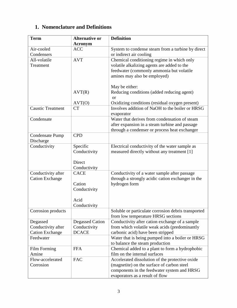
1. Nomenclature and Definitions Term Alternative or
Acronym Definition
Air-cooled Condensers
ACC
System to condense steam from a turbine by direct or indirect air cooling
All-volatile Treatment
AVT AVT(R) AVT(O)
Chemical conditioning regime in which only volatile alkalizing agents are added to the feedwater (commonly ammonia but volatile amines may also be employed) May be either: Reducing conditions (added reducing agent) or Oxidizing conditions (residual oxygen present)
Caustic Treatment CT Involves addition of NaOH to the boiler or HRSG evaporator
Condensate Water that derives from condensation of steam after expansion in a steam turbine and passage through a condenser or process heat exchanger
Condensate Pump Discharge
CPD
Conductivity Specific Conductivity Direct Conductivity
Electrical conductivity of the water sample as measured directly without any treatment [1]
Conductivity after Cation Exchange
CACE Cation Conductivity Acid Conductivity
Conductivity of a water sample after passage through a strongly acidic cation exchanger in the hydrogen form
Corrosion products Soluble or particulate corrosion debris transported from low temperature HRSG sections
Degassed Conductivity after Cation Exchange
Degassed Cation Conductivity DCACE
Conductivity after cation exchange of a sample from which volatile weak acids (predominantly carbonic acid) have been stripped
Feedwater Water that is being pumped into a boiler or HRSG to balance the steam production
Film Forming Amine
FFA Chemical added to a plant to form a hydrophobic film on the internal surfaces
Flow-accelerated Corrosion
FAC Accelerated dissolution of the protective oxide (magnetite) on the surface of carbon steel components in the feedwater system and HRSG evaporators as a result of flow

4
Term Alternative or Acronym
Definition
Heat Recovery Steam Generator
HRSG Boiler system that generates steam using heat transfer from the exhaust gas of a combustion (gas) turbine
Horizontal Gas Path HGP An HRSG with the gas turbine (GT) exhaust flowing horizontally across vertical tubes
HRSG Tube Failure HTF Once-through boiler or HRSG
HRSG that includes at least one evaporator section where water enters and flows in a continuous path leaving the evaporator as all vapor without the aid of a steam drum or recirculating flow
Oxygenated Treatment
OT Combined Water Treatment (CWT)
Feedwater conditioning regime in which alkalizing agents and oxygen are added to the feedwater
Phosphate Treatment
PT Chemical conditioning regime for drum boilers in which alkalinity is achieved by dosing a sodium phosphate compound or blend of compounds to the boiler water
Reaction products Corrosion products developed within HP evaporator deposits
Technical Guidance Document
TGD Cycle chemistry guidance or guidelines freely downloadable from the IAPWS website, http://www.iapws.org/techguide.html
Under-deposit Corrosion
UDC A corrosion mechanism that occurs within (under) thick, porous HP evaporator deposits
Vertical Gas Path VGP An HRSG with the gas turbine exhaust flowing vertically across horizontal tubes

5
2. Introduction: Purpose of Document and How to Use it
IAPWS has previously published six Technical Guidance Documents (TGD) applicable to fossil and combined cycle plants [2-7]. These cover guidance for instrumentation/control [3], volatile treatments (AVT and OT) [4], phosphate and caustic treatments (PT and CT) [5], steam purity [6], corrosion product sampling and monitoring [7], and carryover [2]. Through the use of these documents, optimum cycle chemistry guidance can be developed for combined cycle/HRSG plants. Each TGD contains a number of base cases for the most common combined cycle plant configurations and equipment; importantly, the documents also include a number of customizations that should be made for each combined cycle/HRSG plant. This TGD includes new guidance for the understanding of waterside deposits in the high pressure (HP) HRSG evaporators of combined cycle plants. This is needed because, together with flow-accelerated corrosion (FAC) [8, 9], under-deposit corrosion (UDC) is one of the leading mechanisms of failure and damage in HRSGs [10]. There are three UDC mechanisms: hydrogen damage [11], acid phosphate corrosion [12] and caustic gouging [13]. All three mechanisms require significant deposits on the internal surfaces of the HP evaporator, so understanding how and when these deposits reach a critical level to support the UDC mechanisms is of utmost importance [14], as well as having established criteria of deposit loading above which the HRSG should be chemically cleaned. IAPWS has taken the position in the other TGDs [4, 5] that “high pressure” in the case of UDC refers mostly to pressures above about 7.6 MPa (1100 psi), as UDC is rarely seen in the low pressure (LP) sections of HRSGs. It is recognized that deposits can form in other lower pressure HRSG circuits or coil sections such as the intermediate pressure (IP) and LP Evaporators, and Economizers. These typically can result in other failure mechanisms such as overheating [15]. IAPWS does not have any experience of deposits in these sections leading to UDC failure. Such deposits are generally regarded as an indicator that the chemistry in the HRSG is not optimized according to the IAPWS TGDs. Samples can/should be taken from these sections and subjected to the same analyses as outlined in this TGD for HP evaporator samples, however it is emphasized that this TGD currently only refers to HP evaporator deposits concentrating on those where UDC mechanisms can occur. This is an IAPWS Technical Guidance Document representing the cumulative experience of the IAPWS Power Cycle Chemistry (PCC) Working Group (with representation from 21 countries), and as such should be regarded as an international consensus and guidance for the sampling and analysis of HRSG HP evaporator tubing in deciding whether the current chemistry treatments are optimized and whether the HRSG needs cleaning in the future. This guidance document can form the basis of, but should not restrict, other derivative guidelines around the world from equipment manufacturers and organizations providing guidance on this topic [16]. Experience has indicated that, depending on local requirements, the normal or target values for volatile, phosphate and caustic treatments presented in the Tables of the previous TGDs [4, 5] will provide good reliability and availability if they are customized for each plant depending on the actual conditions of operation, the equipment installed, the materials used in different parts of the cycle, and the condenser cooling media.
6
It is also emphasized that although this TGD provides guidance for the understanding of deposits in HP evaporator tubing of HSRGs, each HRSG manufacturer may provide guidance representing the plant as designed, and these may be slightly different than the operating guidance provided in this document. It should also be noted that this IAPWS Technical Guidance Document does not provide any information on how to chemically clean an HRSG, only on when it needs cleaning. There is sufficient cleaning information in the literature and from specific companies that provide this information and services.
3. Introduction and Importance of HP Evaporator Deposits
3.1 Objectives of this TGD To provide guidance to operators of combined cycle/HRSG plants on:
- Why HRSG HP evaporator deposits are very important in the overall reliability of HRSGs
- Where to sample HP evaporator tubing for analysis of internal deposits - How to analyze HP evaporator internal deposits - How to determine whether the internal deposits are satisfactory for continued
operation without damage due to UDC or need to be removed by chemical cleaning. 3.2 Background to HP Evaporator Deposits and for this TGD The mechanisms that reduce the reliability of HRSGs worldwide have become well established over the last ten years. The leading HRSG Tube Failure (HTF) mechanisms are: flow-accelerated corrosion (FAC), thermal and corrosion fatigue, under-deposit corrosion (UDC) and internal corrosion pitting. All the HRSG components within the temperature range 100–300 °C are susceptible to FAC which involves the single- and two-phase variants [8, 9] predominantly in low temperature (LP, IP and HP) economizers/preheaters and evaporators (tubes, headers, risers and drum components such as belly plates). The same components can also be susceptible to FAC in HRSG designs where the nominal HP evaporator circuit operates for significant periods of time at temperatures below 300 °C (for example, the HP evaporators in older dual-pressure HRSGs, HRSGs where there is only one pressure stage, and high pressure evaporator circuits in plants running for extended periods at low load with sliding pressure operation). The potential for air-cooled condensers (ACCs) to act as a major source of corrosion products should be recognized, particularly at plants where non-optimum feedwater treatment for the ACC is applied together with the lack of a condensate filter [4]. The corrosion products released by the FAC mechanism in these circuits and by corrosion of the non-passivated lower temperature / pressure circuits are transported away from the corrosion site and can eventually reach the HP evaporator and deposit on the internal tubing surfaces. Chemistry guidance for controlling iron transport from ACCs is included in the IAPWS volatile treatments TGD [4].

7
The three UDC mechanisms in HRSGs, hydrogen damage, acid phosphate corrosion, and caustic gouging, occur exclusively in HP evaporator tubing, and all require relatively thick, porous deposits and a chemical (either a contaminant or non-optimized treatment) concentration mechanism within the deposits [10]. UDC damage can occur early in the life of an HRSG due to the inverse relationship between deposit loading / thickness and the severity of the chemical excursion. For hydrogen damage, the concentrating corrodent species is most often chloride, which enters the cycle through condenser leakage (seawater, brackish water or freshwater concentrated within a cooling tower) and via slippage from demineralized makeup water in water treatment plants where ion exchange resins are regenerated with hydrochloric acid [11]. Acid phosphate corrosion relates to a plant using phosphate blends which have sodium-to-phosphate molar ratios below 3 and/or the use of congruent phosphate treatment using one or both of mono- or di-sodium phosphate [12]. Caustic gouging involves the concentration of NaOH that may occur when it is used above the required control level within caustic treatment, with the use of coordinated phosphate with high levels of free hydroxide, with the ingress of NaOH from improper regeneration of ion exchange resins [13], or with condenser leakage (fresh water cooling). Deposition and UDC mechanisms can occur on both vertical and horizontal HRSG HP evaporator tubing. On vertical tubing, the deposition usually concentrates on the internal surface (crown) of the tube facing the gas turbine (GT). It nearly always is heaviest on the leading HP evaporator tube in the circuit as these are the areas of maximum heat flux. Areas of concentration can be the tube circuits adjacent to the side walls or to the gaps between modules due to gas by-passing. The UDC mechanisms can occur in exactly the same areas. On horizontal tubing in vertical gas path HRSGs, both deposition and the UDC mechanisms occur on the ID crown but may occur facing or away from the GT. Damage occurs on the side facing away from the GT when poor circulation rates, steaming or steam blanketing lead to stratification of water and steam and subsequent heavy deposition in a thin band along the top of the tubing corresponding to the steam-water interface during service. When circulation is adequate, the UDC mechanisms occur on the internal crown of the lower tube surface facing the GT. The UDC mechanisms of hydrogen damage and caustic gouging have been well understood for over 40 years [11, 13], and the acid phosphate mechanism since the early 1990s [12]. However, the understanding of how the initiating deposition takes place in HRSG tubing is less well understood, as is the magnitude of deposit necessary for these mechanisms to initiate by concentration within the thick porous deposits. Controlling UDC in HRSGs involves the following chemistry features:
a) controlling corrosion and FAC in the lower temperature sections, b) minimizing the transport of iron corrosion products to the HP evaporator, c) maintaining a low level of deposits within the HP evaporator tubes, d) removing HP evaporator tube samples on a regular basis to determine the
deposition rate, e) chemical cleaning if required, f) controlling contaminant ingress and adding the correct control chemicals, and g) having a fundamental level of instrumentation alarmed in the control room with
suitable chemistry excursion response procedures and operators trained to implement them.
8
To date there have not been any comprehensive studies to characterize and quantify the critical level of deposits (item c) forming in HRSG HP evaporator tubes. The IAPWS Technical Guidance Documents (TGD) define the current optimum cycle chemistry for HRSGs. Application of this chemistry should control FAC in the lower pressure circuits and deposition and UDC in the HP evaporator, and usually involves:
a) Use of only oxidizing treatments in the feedwater/condensate to control single-phase FAC. No reducing agents should be used at any time [4] unless the combined cycle/HRSG is relatively old (1970s) and the cycle contains copper-based feedwater heaters. The oxygen levels need to be high enough to provide surface passivation for the single-phase flow locations [4].
b) Use of an elevated pH in the lower pressure circuits of the HRSG to control two-phase FAC [4]. This can be accomplished by increasing condensate and feedwater ammonia or an amine so that the pH elevates above the range of 9.4–9.6, or by adding tri-sodium phosphate (TSP) or NaOH to the LP and/or IP drums if allowed by the HRSG design, attemperation sources and any inter-pressure connection arrangements [5]. Elevated pH (9.8) operation is particularly important in units with ACC [4].
c) Depending on whether contaminants are, or could be, prevalent in the cycle, add nothing to the HP drum or a minimum amount of only tri-sodium phosphate (TSP) or NaOH [5].
d) Monitor total iron around the cycle with a suggestion that operating within the “Rule of 2 and 5” (< 2 μg/kg in the feedwater and < 5 μg/kg in each of the drums) will provide some indication of minimum risk for both FAC and UDC [7]. Cycling, frequent startups, and improper shutdown / layup protection increase the total iron transported.
f) Fundamental level of cycle chemistry instrumentation [3]. These optimum treatments could change in the future. For instance, the use of film forming products (FFP) may reduce total iron transport and HP evaporator deposition [17]. It will be noticed that avoiding HRSG Tube Failures (HTF), particularly FAC and UDC, and developing the optimized cycle chemistry for HRSGs are intimately related to understanding the formation of deposits in HP evaporators. This is the focus of this IAPWS TGD because insufficient tubes have been sampled worldwide mainly due to the cost of removing samples, the uncertainty as to where to sample, and often to the difficulty of removing the samples from the tightly packed HRSG steam circuits directly in front of the HP evaporator. The previous discussion leads to the need for combined cycle plants to periodically remove HP evaporator tubing to assess the internal deposition [16]. Over the last eight years, a concerted effort has been made to remove and analyze HP evaporator tubes [14] as part of assessment programs for HRSGs [18]. This collection of HRSG HP evaporator deposits now includes tubes from over 100 plants worldwide from HRSGs representing 17 current and past HRSG manufacturers and that have used a wide variety of condensate, feedwater and evaporator treatments within and outside of the IAPWS TGDs. This database of samples and the processes used to analyze them are the basis for this TGD.

9
4. Guidance on Sampling HRSG HP Evaporator Tubing and Analysis
As for all the previous IAPWS TGDs, the uniqueness has been to first delineate base cases and then provide a number of customizations or variants to the base case in a Customization Section. This forces the users / operators to customize the guidance to their specific plants. The same concept has been used in this TGD, where two base cases are considered based on the timing of taking HP evaporator samples for examination.
1. Base Case 1. If the HRSG is not frequently started or fast started and operates with
IAPWS TGD optimum chemistry described in Section 3, and corrosion products are monitored according to the IAPWS TGD [7] and are within the levels suggested, then IAPWS suggests that the first HP evaporator sampling should take place between 20,000 and 25,000 operating hours. This time period could be aligned with the first major GT inspection.
2. Base Case 2. Very often in the combined cycle/HRSG industry, a plant has reached 30,000 hours or considerably longer, and no corrosion product monitoring has been conducted during the operating life, and no HP evaporator samples have been extracted. In this case, the HRSG may be at risk of UDC, and IAPWS suggests sampling at the next suitable outage.
Following the initial tube sampling, the next step is to develop the guidance for subsequent sampling/analysis. The aim should be to link corrosion product monitoring activities and results with the sampling activities and then be able to develop future sampling frequency based on the observed deposition rate.
1. If the Base Case 1 sample shows low levels of deposits (<15 mg/cm2) and no visual indication of any concentration or reaction products within the deposits close to the tube surface (such as illustrated in Figures 3 and 4), and the corrosion products monitored according to the IAPWS TGD [7] are within the suggested levels, then IAPWS suggests that subsequent HP evaporator sampling will not be needed for another 20,000 to 25,000 operating hours. This time period could be aligned with the major GT inspections.
2. If the Base Case 2 sample shows high levels of deposits (>30 mg/cm2), then IAPWS suggests chemical cleaning is needed (according to the IAPWS Deposition Map in Section 5). It is most important following the clean that corrosion products are monitored [7] and that the chemistry is optimized according to the IAPWS TGD to reduce the HP evaporator deposition.
3. It should be understood that the initial and subsequent sampling frequency, the
appropriate time to sample, and the location are also based on previous plant history and experience, particularly any UDC failures. Some of these aspects are discussed in the customization Section 6.
Throughout this TGD, total deposit/oxide loading (mg/cm2) has been used because this indicator is used in many countries of the world as it provides an “average” indicator of total oxide/deposition over an area of the tube. It is recognized that some organizations in

10
some countries use total deposit / oxide thickness (micrometers [µm]), which identifies the deposit / oxide at unique locations on a tube surface. Waterside deposits are generally porous and the porosity is very variable. Correlation between deposit weight per surface area and thickness is therefore very inaccurate. Oxides in superheater and reheater tubes that are formed indigenously by high temperature oxidation in steam are much less porous, so correlations between the two indices are more accurate. For those organizations that prefer to use thickness, it is considered preferable to record values for the maximum and average total thicknesses from both the radiant (facing the GT) and non-radiant crowns (upstream/downstream), usually with emphasis given to the central 90-degree arc which is the usual location of UDC. 4.1 Guidance on Locations for Sampling HRSG HP Evaporator Tubing IAPWS has interfaced with many of the HRSG manufacturers worldwide and also reviewed numerous UDC situations. Based on these, the following primary sample locations are suggested as being representative of where the heaviest deposits form in HRSGs and thus the most representative locations for tube removal and sampling. It is also noted that the large number of deposit loadings, which contributed to the IAPWS Deposit Map in Section 5, were analyzed from tubes removed from these locations.
• For horizontal gas path (HGP) HRSGs, the lead HP evaporator tube (closest to the GT) towards the top of the circuit near to the outlet header (about 1 m down from the header) is the preferred sampling location. Preference should be given to tubes on the extremities of the bundles where gases bypass along the duct, or near the center of the HP evaporator if there is a gap between multiple modules. This is in agreement with the impact of gas by-passing to render the wing tubes in a module more vulnerable to scaling and steaming. Consideration will need to be given if sidewall baffles are installed or not. For units with duct burners, an elevation in line with the duct burner flame could be chosen [16].
• For vertical gas path (VGP) HRSGs, the choice is not always initially as clear. The
first and last tube in the bundle will cover the differences in quality, with preference again for the extremities adjacent to ducting and the gap between modules. Damage occurs on the side facing away from the GT when poor circulation rates, steaming or steam blanketing lead to stratification of water and steam, and subsequent heavy deposition occurs in a thin band along the top of the tubing corresponding to the steam/water interface during service. When circulation is adequate, the heaviest deposition and UDC mechanisms occur on the internal crown of the lower tube surface facing the GT. Also when hydrogen damage or another UDC mechanism occurs, it is often located in the middle of the bundle as well as on leading tubes.
For both types of HRSG, in addition to samples adjacent to the side walls it is also sensible, if possible, to remove tubes deeper in the gas path for comparison purposes. Also, a hot row tube near a liner may be easier to access by cutting through the casing if there is no access to the coil face. The primary sampling locations described above represent a consensus from most of the HRSG manufacturers worldwide, are the basis of the IAPWS Deposit Map in Section 5,

11
and are the most frequently observed locations of UDC. Due to the proximity of the first superheater circuit to the HP evaporator, there is often discussion at the plant level that samples from these locations are difficult if not impossible to extract due to limited access or excessive cost. IAPWS recognizes these factors and suggests that a number of other secondary sampling locations can be used such as the bottom of the lead tube in HGP HRSGs (some hydrogen damage has been observed at this location) and the top or bottom of the lag tube, or even from a bundle further from the GT. It may also be possible to extract a tube sample through the HRSG casing. It needs to be recognized that such secondary locations are not optimal because there is no database of deposits equivalent to Figure 5 for these locations. 4.2 Guidance on Removal of HRSG HP Evaporator Tubing After identifying the sampling location(s), the tube(s) should be photographed and marked using a paint-pen, or similar, prior to removal. The markings should provide the position of the tube in the row (counting from left to right when facing the stack) and in the evaporator depth (first to last row as per gas direction), as well as the gas flow orientation (front or rear with respect to the GT, and upstream/downstream in regards of the water/steam flow). The sample(s) should then be dry cut from the HP evaporator, with the ideal sample length being at least 0.5 m (19 in) to avoid any contamination of the tube waterside over the central portion of the sample by cutting debris. Sometimes, twice the suggested length of tube is removed to provide half of the sample to a chemical cleaning contractor for laboratory analysis and specification of the appropriate cleaning process. Cutting with torches and lubricating saws should not be used to remove tube samples. The ends of the tube section removed should be sealed using plastic caps and/or tape to avoid ingress of foreign material; under no circumstances is packing material or a borescopic type instrument to be inserted into the bore of the extracted tube. However, an opportunity could be taken to inspect the sections upstream and downstream from the sampling position by videoprobe once the sample is removed. A tag should be attached to the tube sample(s) recording information on the station, HRSG identification, vertical height, element/row, tube number and date of sampling. In the event of the tube becoming separated from its tag during transportation, this same information should be provided separately to the receiving laboratory together with a photographic record. Robust packaging should be used in transporting the tube(s) from site to the laboratory; cardboard tubes and wooden packing cases being ideally suited for this purpose. The plant should make sure they have appropriate replacement material for the extracted tube samples. The particular grade of steel tubing used in the HP Evaporator may not be readily available. The replacement tube section does not necessarily need to be finned. 4.3 Analysis for HRSG HP Evaporator Tubing In brief, IAPWS suggests the following four-level assessment methodology for analyzing the tube samples. Details for each are provided in the rest of this section.
• Deposit density to determine the overall loading (mg/cm2, g/ft2). • Optical metallography of cross-sections through the tube, indigenous magnetite and
deposit.

12
• Total thickness of the indigenous magnetite and deposits from the optical metallography of cross-sections through the tube (micrometers).
• Scanning electron microscopy and elemental mapping of cross-sections to determine the distribution of elements and any reaction products within the deposit (see Figures 1-4 in Section 5 as examples). Sometimes it is necessary to use X-ray Diffraction (XRD) to identify the compounds within the deposits.
4.4 Oxide Deposit Weight/Loading Methods There are three widely used methods for determining the specific deposit loading of tube samples from boilers and HRSG evaporators (ASTM D-3483 [19]). With each technique, any fireside deposits are first machined or bead blasted from the tube. If the fins are cleaned by glass bead blasting, care should be taken to ensure that all external deposits and glass bead debris are removed. For finned HRSG tubes, it may be necessary to remove exterior fins to avoid contribution to weight loss from the exterior, particularly if the Solvent method (described below) is used. The deposit loading measurements are performed by longitudinally cutting a six-inch (15 cm) length of the tube section into two coupons representing the hot side of the evaporator tube facing the gas turbine and the cold side of the tube facing the stack. Each side should be photographed and dimensional measurements taken. In each case the deposit weight/loading can be calculated, in which the weight difference prior to and following the removal of internal deposits or the weight of the deposit/oxide is divided by the total surface area of the coupon. The internal deposit loading values recorded should represent the complete removal of the internal deposits and oxides to bare metal so that the value is a combination of indigenous magnetite, deposits, and any reaction products within the deposit; this process should be accomplished with minimal removal of base metal.
• Solvent (Chemical) method: Inhibited hydrochloric acid is used to remove the waterside deposits. The recorded figure for the “oxide/deposit weight per area” is the total loosely adherent material removed prior to solvent removal plus dissolved deposit material (weight of the tube with deposits minus the weight of tube after treatment) divided by the surface area of the tube.
• Glass bead blasting method: The acquired tube sample is weighed and then glass bead blasted to a grey surface appearance and then reweighed. The weight change divided by the surface area of the tube is recorded as the “oxide/deposit weight per area”.
• Mechanical method: This technique is similar to those described above, except that the internal deposits are removed mechanically, typically with a vibrating tool, and weighed. The “oxide/deposit per area” is again calculated by dividing its weight by the surface area of the tube.
All three methods are currently in use worldwide for determining the deposit weight on tubes from HRSG evaporators and fossil boiler waterwalls. However, the method and analytical technique selected substantially impacts the oxide deposit weight results. The solvent method has generally been found to yield larger values (approximately 20% higher) for deposit weight than the mechanical methods. As this method uses inhibited hydrochloric acid, it is similar to chemical cleaning of HRSG HP evaporators and there should be negligible weight loss due to corrosion. It does a better job of cleaning any oxide

13
that may be entrained in the nicks, pores and pits of the rough tube surface, and therefore it gives a more accurate total weight loss. The glass bead blasting technique and results obtained by the mechanical method are comparable to each other. Analysis of the composition of the bulk deposit provides useful supplemental information for evaluating the deposits and for proper planning of a chemical clean. Thus, it is important when assessing the need to chemically clean that an acceptable method is being used and that results are comparable to criteria developed for the method selected. To compare samples from one sampling timeframe to another, the same technique should be used for the analysis.
4.5 Direct Deposit / Oxide Thickness Measurement and Analysis The other three parts of the four-level approach require metallographic preparation of the tube sample for the direct measurement and morphological characterization of the waterside oxides/deposits. The recovered tube length is sectioned axially to expose the waterside surfaces of the respective hot (GT-facing) and cold (stack-facing) sides of the tube with all cutting operations being performed dry. The general and specific condition of the tube bore is then noted with respect to scale uniformity and evidence of any metal loss from the tube substrate. Taking photographs showing the general condition and specific features of interest, such as pitting and scale blistering, from both halves of the sectioned tube sample complements the activity. One of the most important aspects is to record the internal color as illustrated in Figures 1–4 in Section 5, as this provides support for the efficacy of the chemical treatment used in the HRSG. Guided by the visual assessment of the tube bores, micro-sections representative of the general waterside condition are removed from the tube. The tube section or a portion of the tube section is longitudinally split for examination of the internal surface. A 1 inch by 1 inch (25 mm by 25 mm) representative sample is removed from the crown of the hot side (gas turbine facing side) of the tube; similar samples can be removed from areas containing atypical features and/or the cold side crown of the tube. At this stage, external finning can be removed to facilitate easier metallographic mounting. The sample can be coated with a vacuum deposited gold layer to keep the deposit in place and provide delineation between the deposit and the mounting media. Alternatively, the internal surface can be coated with a cold-setting epoxy resin to retain any loose debris present; the inclusion of glass beads in the epoxy mix can significantly reduce shrinkage issues during the curing process. The coated sample is cross-sectioned to obtain a micro-section, which is then mounted and prepared for metallographic examination. A conductive Bakelite type mounting media is a good choice; a cold-setting epoxy resin can also be used. These micro-sections are then mounted before performing metallographic preparation. Non-aqueous sample preparation techniques (dry grinding or non-aqueous lubricants) should be used for deposit composition analysis and elemental mapping as part of the SEM examination; however, wet polishing techniques can often provide a better prepared surface for optical metallographic imaging. This approach provides an appreciation of the scale morphology, characterization of base metal loss if present, constitution (e.g., copper content) and variations in scale thickness, both indigenous and deposited, around the bore circumference, all of which should be

14
recorded, preferably with photographic evidence for subsequent reporting. This is pertinent in the event of incipient UDC being present. This approach also ensures that any water-soluble species, including corrodent species or corrosion reaction products, are retained in the event of conducting elemental analysis using a scanning electron microscope equipped with X-ray analytical tools. Typical examples are included in Figures 1–4 in Section 5. 4.6 Comparison of Deposit Weight Methods and Cross Section / Thickness Measurement Techniques
While both methods can be used to assess deposits on HRSG HP evaporator tubing, the chemical dissolution of the deposit / oxide and subsequent calculation of mass loss utilizes a much larger tube surface area than the thickness measurement method. The overall result from the deposit loading methods will provide an average value over the total surface area and is thus the method that is most often used to evaluate the need for chemical cleaning. However, it will not identify small areas of thick deposit or the nature and porosity of the deposit / oxide, which is the reason why the deposit loading method in combination with metallographic examination provides a more comprehensive assessment. If the solvent solution is analysed post-treatment for its constituents, e.g., phosphate, copper, etc., then a better estimate of the deposit / oxide composition may be obtained. The deposit / oxide thickness measurement is regarded as slightly more subjective, as the sites where thickness is to be measured rely on the objectiveness and experience of the metallurgist or microscopist. Additionally, the nature of this measurement method means that only a small area of the tube surface is examined which may not be solely representative for chemical cleaning assessments. Of course, multiple locations can be analyzed to make this thickness method more representative. Nevertheless, the thickness method enables an indication of the range of oxide thickness present as well as some observations on oxide / deposit morphology, composition and any evidence of incipient degradation to the underlying substrate. It is thus regarded as an important supplementary assessment to the solvent or glass bead blasting techniques. Conversion factors between deposit loading and thickness should be developed in the future so that both indices can be used on an updated Figure 5. The relative merits and limitations of the respective techniques are:
Deposit / Oxide Weight by Solvent and Glass Bead Removal Methods
Deposit / Oxide Thickness by Optical / SEM Examination
Provides a single averaged result for comparison with the IAPWS Map
(Figure 5) in Section 5.
Provides average and maximum thicknesses.
Covers larger surface area and is less susceptible to localized variations in
surface topography.
Data gathered from small surface area. Relies on consistency of deposit
characteristics and morphology. An objective process. Slightly subjective as results depend on
where measurements are taken.

15
Solvent method provides an accurate determination of deposit composition and
speciation.
Same as above. But elemental distribution can be determined by SEM
and elemental mapping. No visual observation of oxide/deposits
possible. Provides detailed visual image of deposit
/ oxide morphology, presence and distribution of non-ferrous material and
pitting (examples are Figures 1-4). Can assist in determining the
effectiveness of a possible chemical clean solvent.
Cannot indicate effectiveness of a cleaning solvent. But can provide an
indication of layering or porosity of the oxide / deposits
The guidance in this table indicates that by using both techniques the information provided will be most useful. The solvent / glass bead deposit removal methods provide the deposit loading results needed to relate to the IAPWS Deposit Map (Section 5), which can be used for determining whether HRSGs need to be cleaned. The metallographic processes can give an indication that a chemical clean is needed if the organization has a thickness criterion. It can also indicate additional information on whether the cycle chemistry in the plant is close to that provided in the IAPWS TGDs or whether it needs to be further optimized.
5. Examples of HP Evaporator Deposits and IAPWS Guidance for Chemical Cleaning
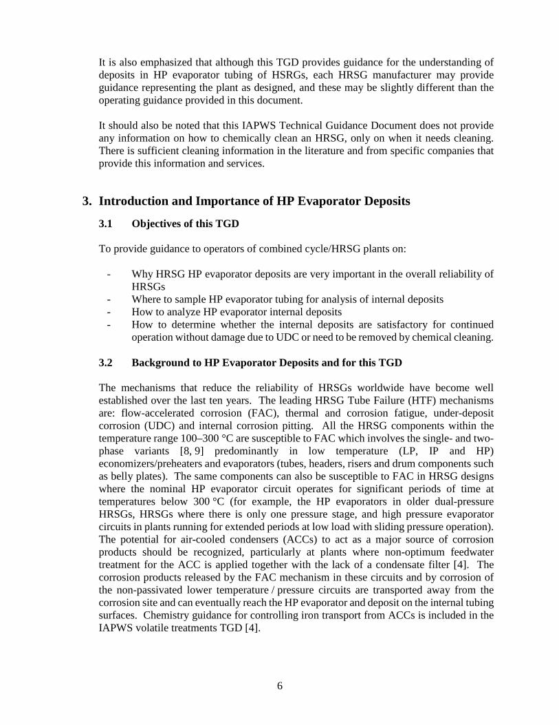
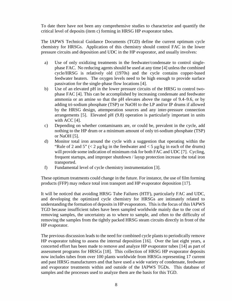
This section is included to show a couple of examples of the analytical procedures delineated in Section 4 and how the accumulation of the information from over a hundred samples of tubes removed from combined cycle plants worldwide have resulted in the IAPWS Deposit Map later in this Section. It should be noted that this IAPWS TGD does not include deposit examples from all combinations of HRSGs examined – only enough to illustrate the analytical processes being suggested. 5.1 Examples of Deposits from HRSGs Operating with Optimum Cycle Chemistry as Defined within the IAPWS TGDs [3-5] HRSG HP evaporator tubes analyzed from units using the current optimum cycle chemistry delineated in Section 3, which includes operating with transported total iron levels [7] within or close to the “Rule of 2 and 5,” always have two important characteristics: an indigenous magnetite protective layer and a thin uniform layer of deposits. Two examples are shown in Figures 1 and 2, where it can be clearly seen that the internal surfaces are red or red/brown, that a thin indigenous magnetite layer is present along the tube surface, and that there is a relatively thin layer of deposits. In Figure 1, the total amount of deposit plus indigenous magnetite is around 11 mg/cm2 (10 g/ft2) after about 16,000 hours of operation. In Figure 2, the total is 7 mg/cm2 (6.5 g/ft2) from another HRSG after a considerably longer operating period (73,000 hours). Elemental mapping confirms that the deposits are essentially iron-based and that there are no concentrations of any compound, corrosion product, or any visible evidence of compounds or species associated with reaction products either within or at the base of the deposit. The indigenous magnetite should always be visible to confirm that no corrosion or incipient UDC is occurring.
16
Figure 1: Deposits formed on an HP Evaporator tube from a HGP triple-pressure HRSG operating with an HP drum pressure of 1800 psi (12.4 MPa) after 16,000 hours. The feedwater treatment was AVT(O) with only ammonia addition at the condensate pump. Only tri-sodium phosphate was added to the HP drum aimed to provide between 2 and 5 ppm phosphate.
Figure 2: Deposits formed on an HP Evaporator tube from a HGP triple-pressure HRSG operating with an HP drum pressure of 1740 psi (12.0 MPa) after 73,000 hours. The feedwater treatment was AVT(O) with only ammonia addition. NaOH was added to the LP drum. Nothing was added to either the IP or HP drums. HP drum pH was typically around 9.6.
17
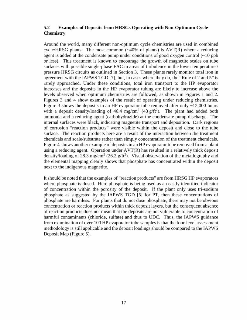
5.2 Examples of Deposits from HRSGs Operating with Non-Optimum Cycle Chemistry Around the world, many different non-optimum cycle chemistries are used in combined cycle/HRSG plants. The most common (~40% of plants) is AVT(R) where a reducing agent is added at the condensate pump under conditions of good oxygen control (~10 ppb or less). This treatment is known to encourage the growth of magnetite scales on tube surfaces with possible single-phase FAC in areas of turbulence in the lower temperature / pressure HRSG circuits as outlined in Section 3. These plants rarely monitor total iron in agreement with the IAPWS TGD [7], but, in cases where they do, the “Rule of 2 and 5” is rarely approached. Under these conditions, total iron transport to the HP evaporator increases and the deposits in the HP evaporator tubing are likely to increase above the levels observed when optimum chemistries are followed, as shown in Figures 1 and 2. Figures 3 and 4 show examples of the result of operating under reducing chemistries. Figure 3 shows the deposits in an HP evaporator tube removed after only ~12,000 hours with a deposit density/loading of 46.4 mg/cm2 (43 g/ft2). The plant had added both ammonia and a reducing agent (carbohydrazide) at the condensate pump discharge. The internal surfaces were black, indicating magnetite transport and deposition. Dark regions of corrosion “reaction products” were visible within the deposit and close to the tube surface. The reaction products here are a result of the interaction between the treatment chemicals and scale/substrate rather than simply concentration of the treatment chemicals. Figure 4 shows another example of deposits in an HP evaporator tube removed from a plant using a reducing agent. Operation under AVT(R) has resulted in a relatively thick deposit density/loading of 28.3 mg/cm2 (26.2 g/ft2). Visual observation of the metallography and the elemental mapping clearly shows that phosphate has concentrated within the deposit next to the indigenous magnetite. It should be noted that the examples of “reaction products” are from HRSG HP evaporators where phosphate is dosed. Here phosphate is being used as an easily identified indicator of concentration within the porosity of the deposit. If the plant only uses tri-sodium phosphate as suggested by the IAPWS TGD [5] for PT, then these concentrations of phosphate are harmless. For plants that do not dose phosphate, there may not be obvious concentration or reaction products within thick deposit layers, but the consequent absence of reaction products does not mean that the deposits are not vulnerable to concentration of harmful contaminants (chloride, sulfate) and thus to UDC. Thus, the IAPWS guidance from examination of over 100 HP evaporator tube samples is that the four-level assessment methodology is still applicable and the deposit loadings should be compared to the IAPWS Deposit Map (Figure 5).

18
Figure 3: Deposits formed on an HP Evaporator tube from a HGP triple-pressure HRSG operating with an HP drum pressure of 1860 psi (12.8 MPa) after 12,000 hours. The deposit density/loading was 46.4 mg/cm2 (43 g/ft2). The feedwater treatment was AVT(R) with ammonia and carbohydrazide added to the feedwater. Tri-sodium phosphate/NaOH was added to the HP drum aimed to provide between 2 and 6 ppm phosphate and a pH of 9.4–9.8. The dark reaction products just above the indigenous magnetite should be noted.
Figure 4: Deposits formed on an HP Evaporator tube from a HGP triple-pressure HRSG operating with an HP drum pressure of 1800 psi (12.4 MPa) after 11,000 hours. The deposit loading is 28.3 mg/cm2 (26.2 g/ft2) and the photographs (elemental maps) for phosphorous and sodium illustrate the reaction products close to the tube surface. The feedwater treatment is AVT(R) with an amine and a reducing agent added to the feedwater. Tri-sodium phosphate and NaOH were added to the HP drum to provide between 1 and 2 ppm phosphate and a pH of 9.4–9.8.

19
5.3 IAPWS Guidance for Chemical Cleaning of HRSG HP Evaporators Examples of deposits from over 100 HRSGs worldwide analyzed as described in the previous parts of this section, and with some examples shown in Figures 1-4, have been plotted to develop the IAPWS Deposit Map, shown in Figure 5. The plants included in the assessment covered a very wide range of HRSGs from 17 HRSG manufacturers operating with HP drum pressures spanning the range 8.9–15.2 MPa (1300–2200 psi) and with deposit loadings up to 136 mg/cm2 (125 g/ft2). The abscissa relates to HP drum pressure of the analyzed HP evaporator tube deposit loadings. It is also noted that in some countries the terms “deposit weight” and “deposit density” are used. All the values of deposit loading within this section and on the Deposit Map were measured using the glass bead blasting method. Some general comments can be made about the three colored cloud regions of Figure 5. The actual colors and shadings do not have any significance and are used to provide descriptive regions and boundaries as follows:
• It should be first noted that the deposit map is only applicable to HRSG HP evaporator pressures above about 7.6 MPa (1100 psi) as discussed in Section 2 relative to UDC mechanisms in HRSGs and the effect of pressure.
• The green cloud represents deposit loading levels from HRSG plants operating with optimum chemistries as currently suggested by the IAPWS TGDs [4, 5] and generally meeting the IAPWS “Rule of 2 and 5” [7] for total iron corrosion products. These generally have deposit loadings below ~12 mg/cm2 (11 g/ft2) and chemical cleaning will not be necessary for these HRSGs. The color of the internal surfaces under these chemistry conditions are generally red/brown, indicative of transported hematite from the lower pressure circuits. Operating times of course might be considered to be an important variable, but current data indicates a broad range from 11,000 to over 80,000 hours of operation. This generally supports similar data from plants operating on the oxidizing treatments, AVT(O), with very low transported total iron corrosion product values when compared to the IAPWS TGD [7]. Importantly, in no case was concentration within the deposit identified or reaction products observed in the deposits near the tube surface. This suggests that concentration reactions of chemical species, such as chloride, within the deposits will not take place when the level of deposition is low, and that the risk therefore for UDC for the HRSG will also be low.
• The yellow cloud generally represents the deposits in the HP evaporator at levels above those in the green cloud and usually represents a move away from the optimum chemistry conditions, such as by the use of reducing agents. This occurs even for units with very low operating hours (< 10,000 hours). The internal surfaces under these chemistry conditions are generally much darker and in most cases black as observed in Figure 3.
• Towards the top of the yellow cloud, and always in the red cloud, there is evidence of concentration within the deposit being identified or reaction products being observed in the deposits near the tube interface. The internal tube surfaces are most often black, indicative of transported magnetite, but this depends on the most recent experience of air in-leakage and the oxygen concentration at the condensate pump discharge. Most significantly, no deposition data for any of these units (those

20
operating with AVT(R)) has been located within the green cloud. Unfortunately, very few of these plants sampled have accurate total iron data to be able to see the elevation above the “Rule of 2 and 5”.
• Clearly as HP evaporator deposits become thicker and exceed about 25 mg/cm2 (20–25 g/ft2) (top of the yellow band and into the red band in Figure 5), they become more porous and thus become more susceptible to concentration mechanisms and corrosion reactions at the base of the deposits next to the tube surface (see Figures 3 and 4). These are the exact concentration processes that initiate UDC and which should be avoided. Thus, if HP deposit loading analyses using the processes in Section 4 indicate levels within and obviously above the red cloud, then the HRSG operator should consider chemical cleaning.
• It must be noted that there are no solid lines between the clouds, indicating that the boundaries are only for general guidance.
• The difference between deposit loadings in HRSGs using the optimum chemistry (defined by the IAPWS TGDs [4, 5]) as compared to the deposit loadings with non-optimum chemistry is very clear. The difference between deposits that do not have concentration or corrosion reaction products and those that do is also very clear with careful metallography as described in Section 4. This new approach of avoiding deposits which have deposit loadings high enough to allow concentration provides the first step in avoiding UDC. The background data can also be used to illustrate how operating with non-optimum chemistries (reducing agents and neutralizing amines and blends) leads to increased transport of total iron across the HRSG and thus to increased HP evaporator deposition. In the future, IAPWS will give consideration to amending this TGD or developing a separate TGD to show the effects of specific chemistry treatments.
• It was mentioned in Section 2 that this TGD will not contain any guidance on chemical cleaning. Readers should be aware that the selection of the right cleaning procedure is not always straightforward, and that a certain amount of caution and pre-testing is advised. The results from the metallurgical analyses of the deposits can be used to identify the chemicals (solvents) that should be used in a chemical cleaning process if the analyses indicate that cleaning is needed.

21
Figure 5: IAPWS Deposit Map for HRSG HP Evaporator tubes. (In some countries deposit loading is referred to as deposit density or deposit weight, and some countries use g/m2. The conversion factor is 1 g/ft2 = 1.08 mg/cm2 = 10.8 g/m2.)
6. Customization of the HP Evaporator Deposit Analysis Procedures and of the Guidance for Chemical Cleaning for HRSG Plants with Different Operating Pressures and other Specific Features Section 4 of this TGD has provided general guidance for two Base Cases that cover the wide majority of the combined cycle/HRSG plants around the world. However, it is emphasized again that this is an IAPWS Technical Guidance Document and that, depending on local requirements, the guidance and analytical processes may need to be adapted and customized for some plants, as there cannot be one set which can be applied to every HRSG worldwide. This customization could be a very important step in determining HP evaporator deposit loading and deriving the need to chemically clean. The emphasis of this section is on operational and cycle chemistry features that could change corrosion processes and transport of corrosion products, and thus deposition on HP evaporator tubing. The most common of these features constitute the topics in Sections 6.1 to 6.7, which relate to the use of non-optimum chemistries not defined by the IAPWS TGD chemistries, not using the IAPWS TGD on corrosion product sampling and analysis [7], and guidance on supplementary inspection of deposits. 6.1 Alternatives to Four-pronged Analytical Approach for Analysis in Section 4
This customization applies to the many organizations and combined cycle / HRSG plants worldwide that do not themselves have the technical capability, access or funds to complete the four-pronged analytical processes described in Section 4.

22
This is most often applicable to the metallurgical examination of HP evaporator tube samples that can provide information on total oxide / deposit thickness and morphology. These processes provide powerful analytical tools that can fully characterize deposits and oxides on HP evaporator tubing, and combined with the solvent / glass bead blasting procedure will provide comprehensive results for operators. In the derivation of the IAPWS Deposit Map and the development of the deposit clouds, the glass bead technique has been used on all the samples. Thus, all samples do not need to be subjected to the full four-pronged analytical approach described in Section 4, and simple deposit loading analysis will suffice to locate the current condition of the HRSG in one of the clouds. It is hoped that, based on this TGD, owners / operators of HRSGs will realize that samples have to be taken and analyzed for deposit loading as a key step in avoiding UDC mechanisms. As discussed in Section 4, metallurgical analysis provides significant additional information in assessing whether or not the chemistry in the plant is optimized, and whether the HRSG needs cleaning. This customization demonstrates that organizations can still use the IAPWS Deposit Map by solely having the deposit loading analyzed to establish the position of their HRSG on the Deposit Map. This allows each organization to know whether their HRSG chemistry is close to optimum or needs improving, and whether the HP evaporator might need cleaning.
6.2 Other Reasons to Chemically Clean HRSGs Although sampling tubes and conducting chemical / metallurgical analyses are clearly the most comprehensive approaches to understanding HP evaporator deposits, they are not the only route to determining the need to chemical clean an HRSG. Consideration should be given to any of these other reasons to chemically clean:
a) Major ingress of cooling water, especially seawater, in the event where all IAPWS TGD parameters in the condensate, feedwater, HP evaporator and high pressure superheater (HPSH) steam were exceeded by large amounts, and particularly when the HP drum / evaporator pH has been depressed below 8.0 and the plant needed to be shut down.
b) Incidents of persistent condenser leakage, severe ingress of contaminants or changes in the occurrence of hideout in the HP evaporator that may initiate tube failures.
c) An occurrence of on-load corrosion damage or UDC that has arisen from the presence of significant waterside deposits, e.g., hydrogen damage or caustic gouging.
d) Serious FAC in lower pressure circuits that could increase the transport of associated corrosion products (total iron) to the HP evaporator.
e) Excessively high levels of total iron corrosion product transport which exceed the IAPWS TGD [7].
f) Excessive use of duct burners in situations where total iron corrosion product transport is high or not measured; including changing from low duct burner use to continuous usage.
g) Extensive re-tubing has been carried out (typically more than 10% of the surface area).

23
h) A major change in operational chemistry is planned. i) Returning a unit to service following extended layup under inadequate
storage conditions. j) Absence of features to mitigate against gas by-passing.
6.3 Alternate Methods for Observing Internal HRSG HP Evaporator Deposits
Many HRSGs have very poor access to remove tube samples at locations delineated in Section 4 because of tight packing of tube modules or because an HP superheater (HPSH) section is located immediately in front of the HP evaporator. Alternative borescopic inspection methods are available to superficially observe the internal deposits. As mentioned previously, sampling tubes and conducting chemical / metallurgical analyses are clearly the most comprehensive approaches to understanding HP evaporator deposits, but borescopic inspection can be used as an initial screening tool. The international consensus is that it is almost impossible to determine the difference from a borescopic surface examination between an HP evaporator with 10 mg/cm2 of deposit and one with 100 mg/cm2. The borescopic process is certainly able to “see” UDC and very heavy deposits in HP evaporator tubes as well as small tubercles that could be indicative of initial UDC or pending tubercle growth, and it has been used for initial observation of single- and two-phase FAC in HRSG lower pressure circuits.
6.4 Comments on Alternate Chemistries to the Optimum IAPWS TGD Treatments The collection of data used to construct the IAPWS Deposit Map has also provided initial information on the effect of a wide range of chemistry treatments. IAPWS is not ready to partition these results until many more samples have been removed and analyzed as a function of the operating chemistry. But it is already very clear that deposit loading results from plants operating with AVT(R), or using reducing agents during shutdown periods on plants that use AVT(O) during operation are always in the yellow cloud or higher and experience higher deposit loadings. It has also been noticed that plants using neutralizing amines and AVT(R) were generally at the top of the yellow cloud or even in the red cloud on Figure 5. Most importantly, there were no deposit loading results from either of these groups of chemistry located in the green cloud showing low deposition. IAPWS is currently developing a series of IAPWS Guidelines on neutralizing amines that might shed some light on these observations and on why the transport of total iron is increased when using a neutralizing amine. There are very few deposit loading results available from plants using film forming products (FFP), which include film forming amines (FFA). IAPWS is currently developing a TGD on FFAs that will provide some of the needed guidance [17]. In general, the IAPWS guidance for plants using chemistries that are not included in the current TGDs [4-7] and for those using FFP in the future is that it is imperative to use the IAPWS Corrosion Product Sampling TGD [7] to determine if the total iron levels are greater or less than those suggested in that document. If the transport levels are higher than suggested, the result could be a higher deposition rate in the HP evaporator and thus the need to chemically clean earlier.

24
6.5 Fast Start or Frequently Started HRSGs
IAPWS recently amended the treatment TGDs [4, 5] to provide guidance on fast start and frequently started HRSGs. These units are known to generate and transport increased levels of corrosion products so the suggested time interval for assessing HP evaporators may need to decrease. If an operator links the requirement for HP evaporator sampling of the HRSG to the gas turbine outage (as suggested as a possibility in Section 4), then a frequently stop / start plant will get to its major outage sooner than a base load plant due to the additional "life hours" consumed by the GT by each start. For each GT start, there are additional "running hours" added on and it is timed to a running hour limit that triggers the outages.
6.6 Units not Pre-Operationally “Acid” Cleaned There are many HRSGs that have not been pre-operationally acid cleaned. These have, however, been pre-operationally water flushed and detergent or alkaline-flushed. The need for a pre-operational acid cleaning depends on a number of factors, one of which is the presence of tube production related oxides, more commonly known as mill scale. During subsequent service, cracks and crevices can form in mill scale that remains adherent as a result of cracking and delamination. This can result in additional sites with the potential for promoting concentration of impurities, from which UDC could develop. If the manufacturing practices do not produce mill scale on tube surfaces, then acid cleaning may not be required. Conversely, if mill scale is produced, then it is generally recommended by the HRSG manufacturers that at least the HRSG HP evaporator circuits are subjected to a full conventional chemical clean in order to prepare the waterside HRSG evaporator internal surfaces to be in the best possible condition for service. For those HRSGs which were not pre-operationally acid cleaned, and mill scale production could have been possible, the presence of residual adherent mill scale is another factor to consider in an assessment of internal deposits and chemical cleaning assessments. In such units, conducting a metallurgical analysis as well as a deposit loading assessment becomes more important. There is the question of whether the internal deposits may be increased on units that were not pre-operationally cleaned because of the remains of mill scale.
6.7 Other Aspects that need Consideration in Understanding HP Evaporator Deposits
There are a number of other combined cycle / HRSG configurations that could be important in determining if the base cases of understanding HP evaporator deposits need to be further customized.
• Units with Once-through HP Evaporators: There is an increasing number of HRSGs with once-through HP evaporator steam generators. It is generally
25
considered that the assessment of the deposits on these units can follow the same processes described in Section 4. It should be noted, however, that there are no deposit loading results from once-through evaporator tubing on Figure 5, but as the once-through units operate at sub-critical pressure it is anticipated that the same criteria can be used.
• Units with Air-cooled Condensers or Air-cooled Heat Exchangers: Increased levels of total iron are often present in these units if the chemistry is not operated in accordance with the IAPWS Volatile TGD [4]. At plants with ACC, the need for HP evaporator chemical cleaning to prevent hydrogen damage is much reduced unless there is a risk of chloride ingress via the demineralized makeup water supply or condensate polishing through the resin regeneration process. When the deposit loading exceeds the recommended criteria (IAPWS Deposit Map) for chemical cleaning, the two other UDC mechanisms are considered possible. Acid phosphate corrosion will only be possible if acid phosphates (mono- or di- sodium phosphate) or unknown proprietary phosphate blends are used. Also there could be a possibility of the plant using incorrect caustic treatment (CT). In these cases, the operator needs to refer to the IAPWS TGD for PT/CT [5]. In terms of HP evaporator deposition, there is also a need to conduct a total-iron monitoring program in accordance with the IAPWS Corrosion Product Sampling TGD [7].
• Units with Aluminum Alloys in the Condenser: Additional testing for aluminum needs to be added to the analyses in Section 4.
7. Bibliography and References
1. IUPAC, Quantities, Units and Symbols in Physical Chemistry, 3rd Edition (RSC Publishing, 2007).
2. IAPWS, TGD1-08, Technical Guidance Document: Procedures for the Measurement of Carryover of Boiler Water into Steam (2008). Available from http://www.iapws.org.
3. IAPWS, TGD2-09(2015), Technical Guidance Document: Instrumentation for monitoring and control of cycle chemistry for the steam-water circuits of fossil fired and combined cycle power plants (Original 2009; Revision 2015). Available from http://www.iapws.org.
4. IAPWS, TGD3-10(2015), Technical Guidance Document: Volatile treatments for the steam-water circuits of fossil and combined cycle/HSRG power plants (Original 2010; Revision 2015). Available from http://www.iapws.org.
5. IAPWS, TGD4-11(2015), Technical Guidance Document: Phosphate and NaOH treatments for the steam - water circuits of drum boilers in fossil and combined cycle / HRSG power plants (Original 2011; Revision 2015). Available from http://www.iapws.org.

26
6. IAPWS, TGD5-13, Technical Guidance Document: Steam Purity for Turbine Operation (2013). Available from http://www.iapws.org.
7. IAPWS, TGD6-13(2014), Technical Guidance Document: Corrosion Product Sampling and Analysis for Fossil and Combined Cycle Plants (2014). Available from http://www.iapws.org.
8. Dooley, R.B., Flow-Accelerated Corrosion in Fossil and Combined Cycle/HRSG Plants, PowerPlant Chemistry 10(2), 68-89 (2008).
9. Dooley, R.B., and Bursik, A., Flow-Accelerated Corrosion, PowerPlant Chemistry 12(12), 738-743 (2010).
10. Dooley, R.B., and Bursik, A., Underdeposit Corrosion, PowerPlant Chemistry 11(12), 760-763 (2009).
11. Dooley, R.B., and Bursik, A., Hydrogen Damage, PowerPlant Chemistry 12(2), 122-127 (2010).
12. Dooley, R.B., and Bursik, A., Acid Phosphate Corrosion, PowerPlant Chemistry, 12(6), 368-372 (2010).
13. Dooley, R.B., and Bursik, A., Caustic Gouging, PowerPlant Chemistry 12(3), 188-192 (2010).
14. Dooley, R.B., and Weiss, W., The Criticality of HRSG HP Evaporator Deposition: Moving Towards an Initial Understanding of the Process, PowerPlant Chemistry 12(4), 196-202 (2010).
15. EPRI, Heat Recovery Steam Generator (HRSG) Chemical Cleaning Case Studies, (2006), 1012756. Available at http://www.epri.com.
16. ASME, CRTD-103 (2014) Consensus on Best Tube Sampling Practices for Boilers & Nonnuclear Steam Generators.
17. IAPWS, Technical Guidance Document: Application of Film Forming Amines in Fossil, Combined Cycle and Biomass Plants (2016). Available from http://www.iapws.org.
18. Dooley, R.B., and Anderson, R., Assessments of HSRGs – Trends in Cycle Chemistry and Thermal Transient Performance, PowerPlant Chemistry 11(3), 132-151 (2009), and in Combined Cycle Journal, First Quarter 2009, 115-130.
19. ASTM D3483-05(2009) Standard Test Methods for Accumulated Deposition in a Steam Generator Tube.