the integrated mode management interface · the integrated mode management interface (immi) is a...
TRANSCRIPT

NASA-CR-202220
IMMI _ -/7 Hutchins
THE INTEGRATED MODE MANAGEMENT INTERFACE
Edwin Hutchins
Department of Cognitive ScienceUniversity of California, San Diego
Final report for grant # NCC 2-591 from the Ames Research Center of
the National Aeronautics and Space Administration in the Aviation Safety/
Automation Program. Everett Palmer served as Technical Monitor.
1 L_
https://ntrs.nasa.gov/search.jsp?R=19960047103 2018-06-28T18:03:58+00:00Z


IMMI Hutchins
The integrated mode management interface
1. Introduction
Mode management is the processes of understanding the character and
consequences of autoflight modes, planning and selecting the engagement,
disengagement and transitions between modes, and anticipating automaticmode transitions made by the autoflight system itself. The state of the art is
represented by the latest designs produced by each of the major airframemanufacturers, the Boeing 747-400, the Boeing 777, the McDonnell Douglas
MD-11, and the Airbus A320/A340 family of airplanes. In these airplanes
autoflight modes are selected by manipulating switches on the control panel.
The state of the autoflight system is displayed on the flight mode
annunciators. The integrated mode management interface (IMMI) is a
graphical interface to autoflight mode management systems for aircraft
equipped with flight management computer systems (FMCS). The interfaceconsists of a vertical mode manager and a lateral mode manager. Autoflight
modes are depicted by icons on a graphical display. Mode selection is
accomplished by touching (or mousing) the appropriate icon. The IMMI
provides flight crews with an integrated interface to autoflight systems for
aircraft equipped with flight management computer systems (FMCS).
The current version is modeled on the Boeing glass-cockpit airplanes
(747-400, 757/767). It runs on the SGI Indigo workstation. A working
prototype of this graphics-based crew interface to the autoflight mode
management tasks of glass cockpit airplanes has been installed in the
Advanced Concepts Flight Simulator of the CSSRF of NASA Ames Research
Center.
This IMMI replaces the devices in FMCS equipped airplanes currently
known as mode control panel (Boeing), flight guidance control panel
(McDonnell Douglas), and flight control unit (Airbus). It also augments the
functions of the flight mode annunciators. All glass cockpit airplanes are
sufficiently similar that the IMMI could be tailored to the mode management
system of any modern cockpit. The IMMI does not replace the functions of the
FMCS control and display unit.
The purpose of the IMMI is to provide flight crews with a sharedmedium in which they can assess the state of the autoflight system, take
control actions on it, reason about its behavior, and communicate with each
other about its behavior. The design is intended to increase mode awareness
and provide a better interface to autoflight mode management.
This report describes the IMMI, the methods that were used in
designing and developing it, and the theory underlying the design and
development processes.
2

IMMI Hutchins
2. Theoretical stance.
Every designed device instantiates a theory about the nature of the
operator and the task(s) to be done with the device. The present generation ofinterfaces is based on a model of cognition in which the person takes in
information, codes it symbolically, and operates on the internal symbolic
representations. Such a model of cognition predicts that operators will be ableto make use of external representations that are already symbolic codes. All
current mode management interfaces represent autoflight modes as text
strings. Many other instruments in the "glass-cockpit" do the same.
The need to provide operators with the right information at the right
time, and to avoid overwhelming the operator with too much information is
widely recognized. This need has led to many efforts to manage information
displays in various clever ways. However, simply controlling whatinformation is presented when is not enough. How information is
represented is also important. In fact, it may be more important than effortsto reduce the "amount" of information presented.
The study of culturally-elaborated, naturally-occurring distributed
cognitive systems leads us to consider how people accomplish cognitive work
by establishing coordination with structure in the environment. This view
puts more emphasis on the role of perception and action in cognition than on
centralized symbolic processing (See Clark, in press). Recent work inembodied and situated cognition question the fundamental status of symbol
processing as a model of internal cognitive processes. In the place of
symbolic processing, we see processes in which internal structure is broughtinto coordination with environmental structure. The theory that is
instantiated in the IMMI is the theory of distributed cognition. (Hutchins,
1995a).
A new understanding of the role of cognitive artifacts has emerged in
the last decade. Rather than amplifiers of abilities, cognitive artifacts are seen
as elements that participate in cognitive functional systems that transcend the
boundaries of the individual. (Cole and Griffin, 1981; Hutchins, 1995a;
Norman, 1993; Hutchins, in prep). In these functional systems, cognitive
work is done via the propagation and transformation of representational
state. Symbolic rules provide one way to transform representational state, but
this is a relatively expensive sort of process for humans. To establish
coordination between text representations of autoflight modes and conceptual
representations of those modes takes considerable effort (Sherry and Polson,
1996).
The analysis of the use of speed bugs in a modern airline cockpit
(Hutchins, 1995b) has lessons for the design of airspeed instruments and theIMMI as a whole. Traditional round-dial speed instruments give the pilot
perceptually salient structure that corresponds to important conceptual states.This is lacking in the existing tapes ( and in existing interfaces in general).
3


IMMI Hutchins
These material structures provide the operator with the perceptual rawmaterials for the construction of coherent conceptual understandings.Conceptually important conditions should be perceptually distinguishablefrom one another. This means more than simply using graphics instead oftext.
Designing perceptual distinctions that mirror conceptual distinctionsaccomplishes several goals at once. First, it puts reasoning into theinteraction with the external world where it canbe accomplished by fastrobust perceptual processesrather than by slow, vulnerable conceptualprocesses.• It makes visualizing the consequencesof mode engagements easyto do. Second,it supports reasoning as an activity undertaken jointly by crewmembers sharing the activity
When we move the boundaries of the unit of analysis out toencompass functional systems that transcend the boundaries of theindividual, we not only find processesat work that we might not havesuspected,but we also find new placesto locate designed activities. It suggestsdesigning crew activities rather than designing just objects or artifacts.
A popular strategy in AI in general and in cockpit automation is to useautomation to build intelligent agents or expert assistants to help humanoperators. This strategy recreatesa number of already difficult problems withcommunication (and intent inferencing. ) A different strategy is to usecomputing power to create worlds where operators get to be smart whileusing simple cognitive processes. An examination of existing highlyculturally elaborated action environments shows how they work to make ussmart. Section 3 below shows how we can use these ideas as design criteria.
In the next section, I will use this theory to interpret the significance of
observed problems.As a final note, it is important to focus on what goes right in current
operations as well as on what goeswrong. The existing aviation system isvery robust and error tolerant (Palmer, et.al, 1994). Many things really do goright in modern mode management. It is as important to understand thesephenomena and to capitalize on the principles underlying them as it is to seewhy things go wrong.
4


IMMI Hutchins
3. Observed problems.
Mode management is a problem. The fact that flight crews are
sometimes surprised by autoflight system behaviors is well documented in
Wiener's (1989) study of the 757 flightdeck. When flight crews ask "What's it
doing now?" and wonder how to make the plane do certain things, there is a
problem. Problems with mode management are also easy to see in ASRS
reports. Vakil, et.al. (1996) surveyed reports for the years 1990-1994 and found
184 reports in which crews reported automation surprises. Palmer, et al.
(1994) in a study of altitude deviations reported to ASRS document several
cases in which flight crew uncertainty about the behavior of glass cockpit
automation led to altitude busts.
Symptoms of this problem show up in a variety of places in the
aviation industry. For example, many Boeing customers who come to Boeing
for training, ask that their crews not be taught the VNAV functions of the
FMCS. These airlines instruct their crews to make all of their altitude
changes in Flight Level Change (FLCH) mode. United Airlines does not teach
VNAV operation in its training center 1. In both cases, the reason given isthat VNAV is too complex to teach. In both cases, it is expected that the
competence required to use this aspect of the system will be acquired "on the
line" as a consequence of learning (and teaching) in actual operations.
Another major carrier (Southwest) has placed metal covers over the VNAV
and LNAV mode select switches on their 737 mode control panels to prevent
crews from using those modes.
Jean Pinet, president of Airbus Industrie subsidiary Aeroformation
describing new A-320 training program called Aircrew Integrated
Management (AIM), recently said,
"We took a prudent approach when we saw the proliferation of flight
modes and configurations on the A320 and other modern aircraft .... We did
not want to teach all of the combinations; we kept a 'classic' approach where
the training emphasis was on those configurations that seem the best adapted
to each of the flight procedures." (Lenorvitz, 1992)
1 I believe that the manufacturers have a special responsibility to provide the
very best training possible. The operators look to the manufacturer as the
source of training concepts as well as hardware. An America West training
captain complained that Amercian West does not provide conceptual training
in the use of the FMCS because none is available from Boeing.


IMMI Hutchins
The authors of the AIM program should probably be congratulated for
their operations-centered approach to training. Still, the proliferation of
modes is perceived as a problem, and the solution taken has often been to
teach only a subset of the full system capabilities. Presumably this is because
the entire system is thought to be too complex for the instructional designers
to describe, too complex for the instructors to teach, too complex for the pilots
to learn, or all of the above.
Autoflight logic is too complex to be easily understood, even,
apparently, by the engineers who created it. The logic diagrams that describethe behavior of the system in all anticipated conditions typically span dozens
of pages. Much of this complexity arises from rarely encountered conditions.
Still, the actual behavior of the autoflight system in operationalcircumstances can be baffling (Wiener, 1989). In spite of this complexity,
pilots should and do develop simplified models of what the autoflight system
is doing.
The decisions to avoid teaching some parts of the autoflight system are
symptoms of serious problems with the new generation of highly automatedaircraft. Granted that vertical navigation involves the constant interaction of
thrust, flight path and speed, there is no need for it to be this difficult. The
engineers have created a system of great utility, but the interface to it is
conceptually so difficult that operators have given up trying to train their
crews to operate and trust instead to the pilots, as a community, to discover
and transmit ways of using it in flight 2.
The difficulties that pilots have with mode management are
understandable given the nature of the current system. This goes for all
major airframe manufacturers. The differences between Boeing and Douglasmode controls is insignificant. Airbus has a different philosophy, but it may
actually be more challenging to the pilot than the American systems becauseeven more is hidden from the pilot in the Airbus airplanes.
3.1. Autoflight modes
An autoflight mode is a means of linking a performance target (speed,
or path) to a control axis (pitch, roll, thrust). It has been said that the flight
management computer system (FMCS) has replaced the autopilot in the
current generation of flightdecks (Robert Dorsett, sci.aviation). This is a
2 Just what it is that pilots are inventing to deal with automated flight modes
that are not taught in schools is a very interesting topic that deserves
systematic study.


IMMI Hutchins
misconception. The autopilot remains as an alternative to the human pilot
as a way of manipulating the control surfaces of the airplane. What has
changed is the way of specifying and computing the targets that autopilot maybe asked to achieve. The FMCS provides new classes of abstractly specified
targets for the Autopilot flight director system (AFDS) which can then beachieved either by the pilot acting on the controls to track flight director cues
or by the autopilot servos acting on the controls.
The introduction of automation is not often driven primarily by
cognitive considerations, but it inevitably has powerful effects on cognition.
Automation on the flightdeck is changing both the cognitive tasks that are
faced by individual crew members and changing the cognitive properties of
the flightdeck itself as a cognitive system.
Although cockpit automation has touched all aspects of flightdeck
operations, it has probably had more impact on flight path management than
on any other aspect. Through the years there has been a continual process of
upgrading and adding new devices and new functions in support of aircraft
flight path control. The innovations have come in waves as technologieshave matured and made new sorts of operations possible. Unfortunately, the
consequence of this process has been the accumulation of a set of poorly
integrated devices and functions for flight path management.
3.2. Flightdeck Automation
Consider a brief history of flightdeck automation beginning with the
Boeing 727.
The 727 flightdeck 3 is a "round-dial" or "steam-gauge" system. The
instrumentation is based on electromechanical gauges. Flight path is
controlled primarily through the flight controls: control column, rudder
pedals, thrust levers, flap handle, trim switches, spoiler lever, landing gearhandle, etc. There is a rudimentary autopilot which is capable of holding an
already established altitude, maintaining a heading, tracking a VOR radial,
and holding an attitude. There is an altitude alerting system, which provides
warnings on approaching or deviating from a selected altitude, but it is not
connected to the autopilot system and the airplane is not capable of capturing
an altitude. Horizontal situation (heading and positional relation to a
specified VOR radial or localizer course) are displayed on a Horizontalsituation indicator. DME (distance measuring equipment) provides
information about distance from station. Considerable cognitive processing is
required to construct and maintain situation awareness in this sort of
flightdeck. The representations that are provided by the instrumentation
3 I use the 727 as a representative of a class of airplanes. The 737
models prior to the -300, and the older DC-9 models prior to the MD-80 are
comparable.
7


IMMI Hutchins
must be coordinated with other representations in the form of air navigation
charts.
The DC-104 represents another step in flightdeck automation. It is still
a "round-dial" flightdeck, but it contains several new features. The autopilot
is much more capable. It can not only hold an altitude or track a VOR radial,
it can capture a specified altitude and capture a radial or a localizer. The
autopilot is capable of controlling pitch to produce a specified target vertical
speed. There is also an autothrottle system which is capable of controlling
engine thrust in two modes: a thrust reference mode in which a particular
thrust parameter (e.g., N1) is tracked, and a speed mode in which thrust is
varied to track an airspeed target. The control of the autopilot and the
autothrottle are brought together on an autopilot panel mounted in the
glareshield. The airspeed, altitude, heading and vertical speed targets to be
provided to the autoflight systems are entered on this panel. Modes of
operation are armed for engagement or selected by button presses and switch
throws on this panel. The selected, armed or engaged modes of flight control
are annunciated on a Flight Mode Annunciator panel. Some of the longer-
range models of the DC-10 were also equipped (retro-fitted?) with RNAV
(inertial navigation) systems that are capable of flying off-airway tracks to
distant navigation fixes specified by latitude and longitude.
The MD-80 added to this a "performance box" which can be used to fly
more fuel efficient climbs, cruises and descents. This Performance
Management System (PMS) is a precursor of the current VNAV functions of
the FMS. The computations of the performance system can be coupled to the
Flight Director and to the autopilot if desired. Inputs to the performance
system are made with a small limited keyboard (digits 0-9 plus characters N, E,
S, W, and/) and PMS data entry and computed data are displayed in a 4 line
24 character per line display. The MD-80 also has coupled autopilot approach
and autolanding capability to Category III minimums.
The Boeing 767/7575 marked another jump in flightdeck automation.
In this airplane, the performance box expanded to become the Flight
Management Computer system. This coupled a comprehensive navigation
data base with autotuning of navigation radios and automatic position
updating. A two-dimensional color lateral navigation display replaced the
HSI 6. CRT displays driven by symbol generators provide great display
4 Early versions of the Boeing 747 and the Mc DonneU Douglas DC-9
have comparable flightdeck designs.
5 The Boeing 737-300, and the McDonnel Douglas MD-88 have
comparable flight deck designs
6 An HSI type display can still be presented by the symbol generators
that drive the computer displays. There are operational reasons for prefering


IMMI Hutchins
plasticity. The inertial reference systems support navigation displays thatshow motion in either track up or heading up modes. They also permitcomputation and display of ground speed and true wind - items that weresimply not possible to compute in earlier technologies.
The plasticity of navigation displays permits the superimposition ofother kinds of information onto the depiction of the aircraft track. Nearbyairports, navigation aids, and weather radar returns can all be superimposedon the depiction of lateral flight path. Information about the vertical aspectofflight path can be added in the form of data blocks attached to waypoint icons.LNAV provides facilities for flying complete complex lateral paths thatconsist of a successionof geographic waypoints. Off airway navigation,complete approach procedures, and autolandings are also supported.Complex vertical profiles can be specified and flown in VNAV modes. The757/767 also introduced additional autothrottle modes. Altitude calloutswere added as part of the newest GPWSsystems.
All of these new facilities increased the capabilities of the aircraftautoflight systems,but also created new systems for the crew to monitor andsupervise.
The present state of the art in flightdeck design is represented by theAirbus A-320, the McDonnell Douglas MD-11 and the Boeing 747-400. Theseairplanes have full EFIS7. Full EFISmeans that the airspeed, altitude andvertical speed instruments are also CRT presentations. This permits soft bugsfor altitude and airspeed aswell asfor heading, decision height andminimum descent altitudes. As an acknowledgment of the importance anddifficulty of keeping track of autoflight modes, the Flight Mode Annunciators(FMA) have been improved, and consolidated.
There is no doubt that these innovations have transformed theactivities of flight crews, changed the cognitive requirements of flight, andchanged the properties of the flight deck asa cognitive system. It is easy tofocus on the shortcomings of the automation, but any evaluation of thistechnology must take full account of the increased functionality and ease ofoperation provided by these systems. In some casesthe automation makespossible things that could simply not be done without it; autoland inzero/zero conditions being perhaps the most striking example. In other cases,crew workload is dramatically reduced; flying a DME arc approach procedureis an example.
Modern flight decks present many alternatives for linking elements ofdescriptions of the aircraft flight path to autoflight systems. One pilot boastedto me that there are six ways to climb or descend the 737-300. The Operations
this old-style display to the map display in some circumstances.
7 All except the standby instruments are now on glass. The Boeing 777may have even the standby instruments on glass.
9

IMMI Hutchins
manual for the MD-88 lists four ways to climb, but on closer inspection onediscovers that there are actually eleven different mode configurationsinvolved in these climb methods.
These alternative methods provide the pilots with functionalflexibility, but the spaceof possible linkages is large and complex. Modechangesoccur at pilot command, but also automatically without pilot actionunder many conditions. Automatic control modes may revert to other modesas a consequenceof pilot action, due to changing flight circumstances, anddue to equipment or signal failure. It is not always apparent which modecombination will best accomplish the desired goals. Modes of operation carrywith them other implications, so that what appears to be a good solution (andmay be at the moment) could become an unsatisfactory solution as flightconditions change. For example, in the Boeing airplanes, the vertical speedmode provides no stall protection in climb. A rate of climb that is perfectlysafe at low altitude may lead to a stall at high altitude.
Even if a pilot knows which mode to select, it is not always clear howto select the desired mode. Some modes will only arm under certaincircumstances and may then only engage when other conditions are met. Inmost cases,the limiting conditions for mode arming and engagement are notrepresented anywhere in the flightdeck system (except in the mind of thepilots if they remember the criteria).
As serious as not being able to engage a desired mode is the inability todisengage an undesired mode. This is sometimes an even more subtleproblem that mode engagement (Sarter & Woods, 1994) Some methods ofengaging one mode may unintentionally lead to the disengagement of othermodes (Palmer, et al, 1994).
Even though autoflight modes are annunciated, it is not clear at alltimes which modes are actually engaged or what the engaged modes implyabout aircraft performance. These problems may be due to the followingfactors: 1) the annunciations are sometimes cryptic (seediscussion of modenames below), 2) the annunciated modes combine with each other incomplex ways; there are modes for thrust, armed captures, roll and pitchguidance, 3) Mode transitions can occur without pilot intervention andsometimes without apparent change in aircraft behavior, 4) the modeannunciations are not prominently displayed, 5) pilots often take the state ofthe MCP or FGCP asa mode indicator (which it is not), 6) some modes havevery complex behaviors, what Vakil, et.al. (1996) call multi-input multi-output (MIMO) controllers.
The complexity of the autoflight systems requires the crew to reason ina complex spaceabout not only the situation of the aircraft and its flightconfiguration, but also about the configuration of the automatic systems.This creates situations in which pilots are unsure what is being done bywhich "intelligent" agents. Pilots are very careful about making clear whichpilot "has the airplane", and usually communicate efficiently about their
10


IMMI Hutchins
intentions. In interaction with sophisticated automation, however, it issometimes not clear to the crew who (or what) has what part of the airplaneand what the automated systems' intentions are. Glass cockpit crewsoccasionally ask aloud, "Why's it doing that?", "What's it doing, now?", "Is itsupposed to do that?" (Wiener, 1989). When unexpected mode behavioroccurs, there is little support in the modern cockpit for determining the causeor communicating about the state of the system.
Most (but, alas, not all) mode selections are made by taking action onthe MCP. The language of execution is button pressesand switch throws onthe MCP. And on the MCP, there is feedback for the flight crew about theactions they have taken. Flow-bars in the switches on the MCP indicate that aselection hasbeen made. For some,but not all, of the switches an illuminatedlight means that the mode can be disengaged by selecting the switch again.The proper evaluation of the consequencesof mode selection actions takenon the MCP cannot be made on the MCP. Instead, evaluation takes place in adifferent language, the language of flight mode annunciation and in anotherplace, on the FMA panel (Douglas) or on the PFD (Boeing).
3.2.1 Failure of integration: the flightdeck tower of babel
The introduction of several waves of automation over the years has
made the modern flightdeck a tower of babel. Flight path information is
expressed in at least ten different identifiable languages: 1. Spoken ATC, 2.Written IFR shorthand, 3. Primary flight control positions, 4. MCP
selections, 5. FMA indications, 6. Primary flight display indications, 7.
FMCS/CDU character strings, 8. Navigation Displays, 9. Published
navigation charts and plates, and 10. The behavior of the aircraft itself.
Some pilots have observed that this list is too short, since the FMS/CDU, the
navigation displays, and navigation charts may each contain a number of
languages themselves. In a typical approach to landing, the crew will
interpret, manipulate, and translate expressions in and among all of these
languages (except perhaps 2).
In some cases, the multi-voicedness of the flightdeck is useful. The
costs of computing some result in a representation that is not well suited to
the computation may be greater than the costs of translating the problem into
another representation and solving the problem there. For example, weather
avoidance planning can be done on the basis of printed descriptions of the
locations of weather fronts, but it is so much easier to do the planning on a
chart that it may be worth plotting the locations of the fronts on a chart before
attempting to formulate a plan for avoiding the weather.
The descriptions of flight path that are supplied to the autoflight
systems always ultimately decompose to heading, altitude, airspeed, and
implicitly, time. The bottom region of Figure 1 shows the basic control loopsof the modern aircraft. These are unlikely to change much in the foreseeable
future. The upper region shows, from the bottom up, the layering of
11


IMMI Hutchins
increasingly complex specifications of flight path that have been introducedover the years. This corresponds to the discussion above of the history offlightdeck automation. The right hand column of the upper section of figure1 lists the media in which the constraints to be satisfied are represented ateach level.
Given the state of the art in technology, there is no need to have thismany representations. What we seenow is a consequenceof a particularhistory of innovation. A considerable reduction in complexity is possiblethrough an integration of these languages into a smaller number of ways torepresent and evaluate flight path information. There is probably no need toeliminate specific functions nor should the ability to revert to simplerdescriptions when they are needed be sacrificed in the interest ofsimplification. The issue concerns the representational media in which thedescriptions are composed and in which the adequacy of the descriptions isevaluated.
12


IMMI Hutchins
Waypt list Waypt Alts, Perf Specwinds
FMCS/MCDU pages
LNAV PATH VNAV PATH VNAV SPD FMCS computed
TOGA
(ground track)
APP
VOR & LOC
TOGA
(+2000 fpm, CMD +10)
GLIDE SLOPE
FLCH
VERT SPD
HDG SEL ALT CAP SPD SEL
HDG HOLD ALT HOLD
FMCS fixed function
Track nav
signal
,. MCP
Target Set
k.Heading A It it ud e Airspeed
2y_
Descriptions of
Flight Path
DirectorAutopilot ...... _',. Flight
tAutopilot Servos
_•,lb
Pilot
vControls
(Yoke, RuddersThrottles, Trirr
Control Surfaces
13

IMMI Hutchins
Figure 1. (Previous page) showing how descriptions of flight path are
linked to the flight controls.
Descriptions of flight path can be linked to the flight controls either by
way of the autopilot servos, or via the flight director and pilot inputs to thecontrols. The modes concerning lateral navigation of the airplane are called
roll modes because they achieve their goals primarily through the control of
the roll attitudes of the airplane. The modes concerning the vertical
navigation of the airplane are called pitch modes because they achieve their
goals primarily through control of the pitch attitudes of the airplane. Themodes concerning the thrust of the engines are called autothrottle modes
because they primarily act through the autothrottle system to control engine
thrust.
In the 747-400, there are 7 roll modes, 9 pitch modes, and 5 autothrottle
modes. Logically 315 mode combinations are possible! Fortunately only
about 60 of these logical possibilities actually occur. That is still a large space
of modes to think about. Is there any way to simplify the conception of the
space of modes and the problems of mode management?
3.3. Operational incidents
The following selection of incidents (most observed from the jumpseat
on actual revenue flights) will serve to illustrate a number of categories of
operational problems with autoflight mode management. Many of these
incidents represent instances of problems that have been identified in other
contexts, training, simulator flights, and in other studies of aviation
automation. Each incident will be analyzed as a small case study. A
theoretical interpretation of the cognitive sources of the incident will be
given. The theoretical interpretations of the problems lead to design goals for
a system in which the observed problems can be expected to occur less
frequently. Furthermore, the theoretical interpretations should support
design goals that will not only fix the observed problem, but other potential
problems as well. (e.g. what are called "metabutton" effects observed in some
lateral navigation events argue for the elimination of metabutton effects in
all contexts of the interface.)
In section 5, actual design decisions based on the design goals are
described. One can then come back to the described incident and ask how the
system with the new design would operate in the circumstances described inthe incident.
These incidents and their theoretical interpretations were also used in
the design of the flight scenarios used in the evaluation of the IMMI
described in section 6 below.
It is widely acknowledged that vertical navigation presents more
difficulties for flight crews than horizontal navigation. (Vakal, et.al., 1996).
14

IMMI Hutchins
Horizontal or lateral navigation is simpler than vertical navigation because it
is governed by a single roll axis, roll, and because it is supported by the lateral
navigation display (moving map). There are, however, still some observedmode management problems in the domain of lateral navigation. We will
begin with a few of these.
3.3.1. Modify RTE, execute, and then...
Climbing out the airplane was given a vector to intercept a
published SID routing. The airplane was then given a vector for
traffic that was not a vector to intercept. Finally the aircraft was
cleared to resume the departure. At that point, the captain set up
the intercept by modifying the RTE-LEGS page of the CDU, but did not
press the NAV button to arm the lateral navigation function. As aresult, the aircraft flew, in heading select mode, through the
departure route by about 2 miles. The captain noticed the deviation
of the airplane symbol from the magenta track on the navigation
display, ND, and brought the airplane around with heading select. He
then selected NAV, which engaged. No mention of a deviation from
course was made by ATC. The captain subsequently complained that
the automatics had failed to capture the route.
This a classic case of Polson calls an "and then" problem (Poison:
cognitive walkthroughs). The modification to the route is made on theMCDU, (and in Boeing airplanes, is executed there). If a mode that uses the
modification is not already engaged, it is then necessary to arm that mode onthe MCP. This additional action is difficult to remember because it is carried
out in a different place from the route modification actions and because theexecution of the modification has the feel of a completion to the route
modification plan. Design goal: Route modification and mode selection
should take place in the same location as a single course of action. The IMMIdoes not address the problem of route creation and modification. A second
design goal is to make the distinctions among modes more perceptuallysalient and conceptually meaningful on the NAV display. This can easily be
done.
3.3.2. Engage LNAV with active waypoint on wingtip
Just prior to top of descent, the aircraft was given a vectorfor traffic. When the captain attempted to re-engage NAV, the
aircraft made an unexpected turn to the right. The captain engaged
heading select and spun the heading bug to the left to reintercept the
FMC route as displayed on the ND. After the airplane was again
established on a heading to intercept the route, the captain selected
15

IMMI Hutchins
NAV and the plane made another unexpected turn. He went back to
heading select. Finally, he was able to get NAV to engage and
continue on course as he wanted it to.
The cause of this unexpected behavior by the autoflight system is that
while being vectored the airplane had almost, but not quite, passed the active
waypoint. With the active waypoint having a relative bearing of less than 90
degrees, it will not transition. The airplane was trying to fly to a waypoint
that was nearly abeam of the plane, thus entering an unexpected steep turn.
This problem has been observed in actual and simulated flights in
many glass cockpit airplanes. It is possible that some crew members consultneither the ND nor the ACT F-PLN or RTE-LEGS pages of the FMS before re-
selecting NAV. For those who do consult the ND, the active waypoint is not
saliently marked on the ND. Down-course waypoints are white, the active
waypoint is magenta. That makes sense because the active route is displayed
in magenta, and for the sake of consistency, all items depicted in magenta areelements of the active route. Unfortunately, there is a conflict here between
consistency and discriminability. That is, the inactive waypoints are
perceptually easier to find on the display than the active waypoints. This isbecause the white symbology contrasts with the magenta route line while the
magenta symbology blends into it. The white symbology also has a bettercontrast with the display background. Design goal: Make the active waypoint
perceptually more salient on the lateral navigation display.
The deeper problem here is that the NAV button on the GCP (or
LNAV button on the MCP) is what Ev Palmer (Palmer, personal
communication) has called a "meta-button." The structure of the button
itself contains no information about the content of the mode that it selects.
The meaning of the button is "fly the lateral route described in that active legs
page beginning with the active waypoint." The route description is availableon the RTE-LEGS page of the CDU (which might not be visible when mode
selections is made, and on which the information is in text form), and in
graphical form on the NAV display (but as noted above, the active waypointis not salient), but this information is not represented in any way on the
glareshield where the mode selection is made. The act of selecting the mode
can proceed to conclusion without the pilot processing any representation ofthe content that will be evoked by the engaged mode. This is what makes
unintended outcomes possible. Design goal: Require the operator to process
the content of the mode in the act of selecting any mode. A simple way to do
this is to have NAV mode selected by touching the active waypoint icon on
the NAV display. This requires a bit more work than pressing the NAV
button on the GCP because the pilot must first find the active waypoint in
order to touch it. This search and touch activity make the spatial relation of
the active waypoint to the airplane apparent to the pilot. This extra work is
part of the work the pilot should always do before engaging the mode in anycase. The wider design implication is that for all modes, the action taken to
16


IMMI Hutchins
select or engage the mode should somehow bring the operator into contactwith easy to process representations of the specific consequencesof engagingthat mode.
3.3.3. Heading bug behind the airplane
This one was observed in a simulator flight rather than in revenue
service.
The departure SID contains a turn of nearly 180 ° early in the
procedure. The heading bug is lined up with the runway for takeoff.
LNAV is engaged after liftoff and the procedure is flown as depicted.
After turning more than 90 °, ATC calls traffic and asks for a turn.
The crew engages heading select, but now finds that the heading bug
is behind the airplane and not visible on the nav display. The
airplane continues its uncontrolled turn until the crew can spin the
bug around in front of the airplane.
The root of the problem here is that the button press that engages
Heading Select mode is a meta-button. Its meaning is roll to capture the
heading indicated by the current position of the heading bug (wherever that
may be). The current position of the heading bug is indicated as a number of
degrees in the window above the heading select knob. This representation
does provide some information, but it is not in a form that is easy to process.
Suppose ATC said turn left 15 ° for traffic. One would have to read one's
current heading, and then subtract 15 ° to get the desired heading. Now,
suppose the desired heading is 320 and the heading window reads 130. which
way should one spin the bug to get it to the desired heading? The act that
engages the mode does not require the crew to process any aspect of the
heading that will be selected. The crew may use the heading window todetermine the current location of the heading bug, but this representation is
not easy to process. Furthermore, the heading bug itself is only visible when
it is ahead of the airplane symbol on the navigation display. When the
heading bug is on a heading that is behind the airplane, the bug itself is
hidden. Many instructors and line pilots emphasize the importance of
establishing a habit of keeping the heading bug in front of the airplane in
order to eliminate this problem.
Design goal: Like the problem with wingtip LNAV, the solution to the
meta-button problem here is to require the crew to process the content of the
mode that will be selected in the act of selecting the mode. In this case, that
can be accomplished by having heading select mode be selected by touching
the heading bug on the NAV display. This implies another design goal,
having the heading bug always be visible on the NAV display. A further goal
is to have the display itself change in some way to indicate that the heading
bug is going behind the airplane.
17

IMMI Hutchins
We now turn to the more complex, and less well supported, task ofvertical mode management.
3.3.4. Unexpected leveloff at crossing restriction
The Peble One departure out of San Diego includes an at-or-below
altitude restriction early in the SID. This restriction protects airspace used by
fighters operating out of Mirimar Naval Air Station. I have observed this
departure from the jumpseat many times. Out of 5 departures I observed in
757s, three crews were surprised by an unexpected leveloff at this altitude
restriction. Other researchers (Palmer, Degani) flying this leg in 757 have also
observed this problem. The following two incidents are typical.
Peble incident 1: The Peble one departure was selected to go
with the company route. The departure clearance was to 14 thousand.
The crew briefed the departure and put 8000 in the altitude window
"just to be safe." After TOGA, the climb was commenced in FLCH
and LNAV. Out of 4,000, the aircraft was cleared unrestricted to
14,000. The crew put 14,000 in the window, and engaged VNAV.
Approaching 8,000', the aircraft began to leveloff. The Captain
said, "Oh, I know what it's doing" and selected FLCH. He then
deleted the restriction from the RTE-LEGS page and reengaged VNAV.
Peble incident 2: The crew carefully briefed the departure, and
talked about the restriction. They put the company route with the
Peble 1 departure in the CDU. After takeoff the aircraft was
cleared unrestricted to 9000'. The airplane leveled at 8000'. It
took quite a while for the crew to figure out why it leveled off. The
FO finally pushed FLCH to resume the climb. By the time they began
to remove the restriction, the waypoint had transitioned.
In these two cases, the MCP window altitude seems to be the most
salient representation of anticipated flight path. The restriction to pass a
waypoint at or below 8000' is visible as text on the RTE LEGS page of the CDU,but is not obvious even if that page is displayed. In each case, the clearance to
climb unrestricted should lead the crew to delete the restriction from the
FMS.
In a third case involving this departure (reported by Palmer, personal
communication b), the crew were required to meet the altitude restriction.
They did so successfully, but while trying to confirm that they had done so,
they failed to continue the climb after the waypoint as expected.
The problem here is that the relevant system state - the representations
of the altitude restriction - are weak and possibly hidden. Sherry and Polson
(1995) discuss this sort of unexpected level-off as an example of the weakness
18

IMMI Hutchins
of current mode annunciation systems. Design goal: provide a graphical
representation of the future vertical trajectory of the airplane. Just as thelateral navigation display makes the lateral path visible, a vertical navigation
display could represent the vertical path. It should be noted that there are
many problems with constructing vertical situation displays.
3.3.5. Unexpected level-off at cruise altitude
The aircraft was climbing out to the west with VNAV, LNAV
and right autopilot engaged. Out of FL240 the aircraft was cleared
to FL350. The captain put 35000 in the MCP altitude window. The
FMS had been programmed for an initial cruise at FL310. (It is not
known why the clearance did not match the programmed cruise
altitude). The airplane was handed off to a new sector at about
FL300. As the Captain began to check in, the airplane began to
capture FL310 so he said, "Callsign 281, leveling at FL310." The
controller replied: "1 thought you were cleared to FL350, Sir." The
captain glanced at the altitude window (he must have immediately
figured out what happened), and said: "Yes, I guess we were, but
we'd like to stay here if the ride has been okay here."
In this case, it is not clear that the captain had well formed expectation
concerning the behavior of the airplane, but he and the FO were surprised
that the airplane had leveled off before reaching the altitude in the MCP
window. The problem here is that there are multiple descriptions of flight
path, these descriptions are not always consistent with one another, andwhich of the descriptions is actually controlling depends on situational
factors. The mismatch between the representation of flight path programmed
into the FMC and the representation on the MCP leaves the behavior of the
airplane ambiguous. The MCP representation occupies a more centrallocation in the cockpit, but in this case, the less accessible FMC representation
is the controlling representation. Again, the difference between what is
programmed into the FMS (not immediately accessible - but operative) and
what is displayed on the MCP (immediately accessible -but not necessarily
operative) led to an altitude awareness problem. These discoordinations are
symptoms of the complexity of operation via the two different interfaces
located in different parts of the cockpit.
Design goal: To have a single representation in which all descriptions
of flight path are displayed in such a way that it is easy to determine which
will be controlling in any situation.
19

IMMI Hutchins
3.3.6. Failure to note FMA change
Navigation error on the Border 3 departure. Just before
reaching the turn at PGY 19 DME cleared direct PGY. FO programs
FMS, Capt goes to heading select. I think he went for a 080 ° heading
(the final inbound course to PGY if the whole SID was flown.) With
the FMS programmed, should have gone back to LNAV. I think the FO
did not know that the capt had selected heading select. So FO
believed LNAV still selected. 080 ° heading brought us over North
Island. Capt noticed then and reselected LNAV.
This should have been easy to see on the annunciators on the PFD, but
I have heard many complaints by crew that they do not use the annunciations
as much as they should. Autoflight instruction packages always stress:
"When you make a change up here (MCP), you've gotta look down here (PFD
annunciations) to make sure you really have what you think you have."
The problem here is that the annunciations are cryptic and not salient. Also,lateral mode status is not indicated on the map display itself. Design goal:
indicate lateral mode status on the map display, and do it is a way that makes
the mode annunciation perceptually salient.
3.3.7. Unanticipated automatic mode transitions
VNAV PTH reverts to VNAV SPD mode without warning in
overspeed descent. Sherry and Polson (1995) also discuss this automationbehavior as a context for crew confusion. Vakil, et.al. (1995) describe three
kinds of mode transitions: commanded mode transitions, immediate
consequences of crew mode selections; uncommanded transitions, usually
invoked by the automation as envelope protection; andautomatic/conditional transitions, such as when an armed mode engages.
Design goal: Indicate impending uncommanded, and automatic/conditional
mode transitions.
3.3.8. Knowing which modes can be engaged when.
On the climb we were given a speed restriction to maintain
250 until further advised. It wasn't until we were out of FL250 that
we got econ speed. I was looking at the captain's climb page and
could see that econ speed was 309 KIAS or Mach .797. I wasn't
exactly sure how to get back to econ speed since we had the speed
intervention showing in the window 250. When the captain asked the
FO to restore the econ speed, the FO reached up and pressed the
VNAV button. VNAV was already engaged though, so this had no
effect. (Note: part of the logic of the system is that modes are
20

LMMI Hutchins
normally only dis-engaged by the selection of another mode.) The
captain pointed to the speed select knob, making a pressing motion.
the FO pressed the knob. The window blanked and the command speed
bug jumped up to the econ speed.
Technically, this is not a mode change. It is instead a change in the
target for the engaged mode. Still, it presents a problem for the crew. There
is nothing to tell the pilot that econ speed target will be restored when one
pushes that knob, or even that the knob is pushable. This is a case of more
hidden system state. Design goal: represent engaged, armed, and selectable
modes and their performance targets (speed, path) explicitly.
This raises the more general issue of knowing which modes can be
selected for engagement at any point in time.
3.3.9. Why SPD is not selectable when in FLCH, VNAV or
TOGA.
At the end of a VNAV-PTH descent, the FO wanted to reduce
speed. He reached up and pressed the SPD button on the MCP.
Nothing happened. He pressed it again, and still nothing happened.
He pressed it five times in all before giving up and selecting
vertical speed (which automatically activated SPD mode).
In this example, it is clear that the FO did not know that the SPD mode
is not available for selection when in FLCH, TOGA, or any VNAV mode. A
pilot could memorize this fact, but there are many other facts just like it.Fortunately, there is a simple conceptual regularity in the system that implies
this constraint. This regularity will be presented below in the discussion of
the conceptual organization of autoflight functions. A better solution wouldbe to base one's knowledge of this constraint on the underlying regularity.
Unfortunately, the existing interface masks the underlying conceptual
regularities that govern the behavior of the autoflight system. Design goal:Present for selection, only those modes that can be engaged or armed from the
current operating mode. Design goal: Associate salient perceptual regularities
in the display with the underlying conceptual regularities that govern the
behavior of the autoflight system.
3.3.10. Mode selection in wrong operational context: Killing the
capture
Palmer (1994) reports a case from a simulated flight in which a pilot
intending to soften a level-off maneuver caused a failure to capture the target
altitude. In some automated airplanes, pilots find the level-off maneuver to
be somewhat abrupt. One way to provide more passenger comfort is to select
21


IMMI Hutchins
V-SPD mode prior to the capture and to reduce the vertical rate at which thetarget altitude is approached. This normally works fine. If however, theselection of V-SPD is made after the altitude capture hasbegun, the selectionof the new mode will "Kill the capture." In the caseobserved by Palmer, thenew mode selection came less than a second late. Since modes are notannunciated in the sameplace where mode selections are made, there is apossibility that the operating context could changebetween the time the pilotdecides on an action and when the pilot takes the action. Design goal: Put themeans of evaluating the current state of the system, making changes to thesystem, and assessingthe consequencesof changesall in the same location.
As long asthe parameters of flight path are specified through the CDU,the autoflight modes that link those parameters to the controls are selectedvia actions on the MCP, the consequencesof mode selection actions areevaluated on the FMAs and the compliance of the airplane with the specifiedparameters is monitored on the PFD and ND, there will be problems likethose observed in these flights. These flightdecks scatter flight path displaysand controls all over the instrument panel.
3.4 Mode Naming
A lexicon for verbally representing the states and guiding one's own
and the attention of the other pilot is needed. How are pilots going to talk
about what they see and what they are doing on this interface? This raises the
issues of mode naming. Currently, the mode naming and the representations
of the modes are a single system. The mode names appear as text in the mode
annunciation. Pilots refer to the modes by their text names or phonetic
variants of them. Because of display space constraints, most text
representations of mode names are contractions of longer words. Sometimes
pilots use the longer words - expanding the contraction, e.g. LvlChg= Level
change. Sometimes they coin a new phonetic token based on the contraction.
e.g., FLCH = flitch. Even within the current system of mode naming it is
possible to make improvements along the lines of the theory presented here.
That is, conceptually similar modes could have conceptually similar names.
Some of this is present in a partial compositional structure of names. For
example, the vertical navigation modes in which performance targets are set
by the FMCS all begin with the character string "VNAV". One can see why
engineers would name modes this way. Grouping modes that are controlled
by the FMCS reflects both the history of the introduction of modes and thenature of the data flow within the autoflight system. However, there are
other ways to group modes. For pilots, the source of the target may not the
most important feature of modes. From an operational perspective, VNAV-
SPD may be more similar to FLCH (both are pitch to target speed modes) than
it is to VNAV-PTH.
The general problem here is that the mode space is multi-dimensional,
and text string annunciations tightly constrain the number of independent
22


IMMIHutchins
features that can be meaningfully distinguished in the representation ofmodes. The hyphenated mode names convey only two dimensions. Thegraphical depictions of the IMMI permit simultaneous representation of awider range of features - up to four dimensions simultaneously. However,regardless of the capabilities of graphic displays, the mode naming issueremains a factor in crew communications and reasoning about modes.Airbus naming conventions may have some advantages because they aremore explicitly compositional. For example, the difference between whatBoeing calls VNAV-SPD climb and FLCH climb is noted in the Airbus systemas the difference between managed speed climb and selectedspeed climb.
3.5 Folk models:
The failure of the current interfaces to provide the crew with the raw
materials necessary to construct coherent models of the conceptual
organization of autoflight, and the failure of most manufacturer and airline
training programs to teach the conceptual structure of autoflight leaves to
pilots themselves the job of trying to come up with conceptual models tounderstand the behavior of the systems they use. Unfortunately, the
regularities that are most important are often masked in the current designs.
Sometimes, these folk models are quite good. In some cases they are
charmingly naive, and on other cases they are probably quite dangerous. Here
is an example of a naive model. Most airlines specify a procedure for
autopilot use in which the autopilot that is used to control the airplaneshould not also be used to drive the flight director of the pilot flying. In
airplanes with three autopilots, the center autopilot is usually engaged. In
two autopilot airplanes, the autopilot on the side opposite the pilot flying is
used. One captain told me that you can't use same autopilot to drive the
servos and to generate the f/d command bars. His folk theory to account for
this fact was a resource limitation argument. He claimed that "the box can't
drive both at once. That's why with 3 autopilots, we normally use center in
command." A better reason is that if an autopilot fails active, you don't want
it sending bad information to both the f/d command bars and to the servos. If
these are on separate boxes, then if the one driving the command bars fails,
the airplane will continue flying fine. If the one driving the servos fails, the
pilot will be able to use the command bars to recover.
The MCP is not completely lacking in conceptual organization. While
explaining to me how the MCP is laid out, one captain seemed to achieve the
insight that N1 and SPD are thrust modes and that FLCH and VNAV are
pitch modes. N1 and SPD are on the left of the speed select knob while FLCHand VNAV are to the right. Unfortunately, the conceptual organization of
the MCP is at best local and inconsistent. Another pilot (B-737-300) told me
that "this stuff up here (top row of buttons on MCP has to do with this (the
MCP). This stuff down here (bottom row of buttons) has to do with this
(FMS). "
23


IMMI Hutchins
This desire on the part of pilots to read conceptual meaning into thespatial layout and the behavior of the MCP and other mode managementdisplays and controls suggestsa final design goal: to build an interface inwhich the physical layout and behavior of the displays and controls mapseasily onto the underlying conceptual regularities of the autoflight system.
24

IMMI Hutchins
4. A conceptual analysis of autoflight modes
If the analysis presented above is correct, then making the concepts that
underlie autoflight operations more explicit in the behavior of the interface
may improve operability and the rate and quality of learning. What are the
underlying conceptual regularities and conceptual distinctions? Some of
these come from the realm of flight in general (e.g. the distinction between
pitching to a speed and pitching to a path) and some are specific to automated
airplanes (e.g. is the performance target set by the crew or computed by the
flight management computer system.)
4.1. Methods for discovering the conceptual basis.
Over the years cognitive anthropology has developed several methods
for discovering conceptual structures. First and foremost among these
methods is participant observation in which the researcher participates in the
normal activities of the people and thereby learns to speak and act like the
people do (Agar, 1980, 1986). Engaging in appropriate talk and action requires
at least partial mastery of the conceptual structures that the natives use to
organize their own behavior. Over the past 7 years, I have become a pilot. I
now hold a commercial pilot's license with multi-engine and instrument
ratings. This, of course, does not mean that I can claim to know the
conceptual structures on the basis of introspection, but it has permitted me to
engage real line pilots in meaningful discussions concerning the problems
they face. I have conducted dozens of interviews with pilots, both in the
cockpit and out. Analysis of discourse and interviews is a second major
technique of cognitive anthropology (Hutchins, 1980, Holland and Quinn,
1984; D'Andrade, 1995).
To construct a knowledge of autoflight systems in state of the art
aircraft, I have completed the ground schools for the Boeing 747-400 and the
Airbus A-320. These ground schools do not qualify me to fly these airplanes,
but they do permit me to observe pilots in flight in a different way. Before I
took the training, I could see what pilots were doing. After the training, I
could see not only what they were doing, but what they could have done but
chose not to do. These courses enhanced my abilities as an observer. I have
logged over 300 hours of jumpseat observations of line operations indomestic and international flights. These observations are the basis of the
observed problems section of this paper. Participation in the training also
gave me access to training materials, operational manuals, pilots, instructors,
and, at Boeing, access to engineers who designed the systems.
A third method for discovering conceptual structure is called
componential analysis (Goodenough, 1957; Romney & D'Andrade, 1961;
Werner & Schoepfle, 1987). The goal of componential analysis is to isolate a
set of underlying distinctions that can account for the system of meanings in a
noun domain. In this case, the names of the autoflight modes constitute a
25


IMMI Hutchins
noun domain. A componential analysis of the mode names reveals the
underlying conceptual distinctions that account for the differences in
meaning among the mode names. A comparative componential analysis
contrasting the underlying distinctions for the Boeing and Airbus mode
naming conventions has been completed 8. The major results of this analysis
will be given below.
400.
4.2. Autoflight modes
The following sections present the autoflight modes for the Boeing 747-
This aircraft was the original target for the IMMI development.
4.2.1. Roll Modes
The roll modes for the 747-400 are given the following names: HDG
SEL (heading select), HDG HOLD (heading hold), LNAV (lateral navigation),
TOGA (takeoff and go-around), LOC (localizer), ROLLOUT, and ATT
(attitude). The conception of roll modes can be simplified considerably by
noting that each mode is no more than a method for computing the
directional target for the airplane. While there are seven roll modes, the
modes fall into two major classes: modes in which the target is the heading
of the airplane, and modes in which the target is the ground track of the
airplane. The heading based roll modes are HDG SEL and HDG HOLD. HDG
SEL turns to the airplane to a selected heading and keeps it on that heading.
HDG HOLD rolls the airplane's wings level and holds the heading that was
achieved when the wings came level.
Further distinctions among modes are made on the basis of the sources
of track information. In LNAV mode, a ground track is computed by the
flight management computer system, based on inputs to the MCDU. This
ground track may be used to do the equivalent of VOR radial tracking,
although it is the ground track defined by the radial, rather than the VOR
signal that is being tracked. LOC and ROLLOUT modes track the localizer
signal of an instrument landing system approach facility. TOGA uses the on-board inertial navigation system to determine the ground track of the
airplane at the onset of TOGA guided flight and uses that ground track as the
target.
Ground track can thus be defined by geographic coordinates (LNAV), by
signals from ground based navigation aids (LOC and ROLLOUT), or by a
momentary sensation of the inertial reference system (TOGA).
8 The details of this method and its results will be reported in detail
elsewhere.
26


IMMI Hutchins
The one remaining roll mode, ATr (attitude) is an infrequently usedreversion mode. It engagesonly when a flight director is turned on in flightafter a period in which neither flight director and none of the autopilots havebeen engagedand the bank angle exceeds5°. Its main function is to provide a
flight director guidance mode that keeps doing what ever the airplane was
doing before the flight director was turned on.
4.2.2. Pitch Modes
The pitch modes are: TO/GA (takeoff and go-around), ALT (altitude),
V/S (vertical speed), VNAV PTH (path), VNAV SPD (speed), VNAV ALT
(altitude), G/S (glide slope), FLARE, and FLCH SPD (flight level change,
speed).
4.2.3. Autothrottle Modes
The autothrottle modes are: THR-REF, THR, HOLD, IDLE, and SPD.
These come in two flavors: speed modes and thrust modes.
4.3. Mode Interactions
Fortunately, the Roll modes are essentially independent of the Pitchand Autothrottle modes. The exceptions are that the toga and rollout roll
modes only occur with certain pitch and autothrottle modes. Unfortunately,
this independence is conceptually masked by the fact that the flight modeannunciator formats of both Boeing and Douglas aircraft display roll mode
between the pitch and autothrottle mode displays. This is probably an
attempt to maintain consistency with the layout of the primary flight displaysin which the ADI and the HI (primary roll instruments) lie between the ASI
(thrust instrument in level flight) and the Altimeter (a pitch instrument in
level flight).
Treating roll modes independently and knowing that there are few
interactions between roll modes and other modes simplifies the mode
management problem considerably.
There are, however, significant interactions between pitch and
autothrottle modes, and it is here that most of the conceptual problems seem
to arise. Segregating the modes into classes and showing a simple set of
relations among the classes may help to simplify the conceptual space.
The rule is that whenever the pitch mode is controlling to a speed
target, the autothrottle mode will be controlling to a thrust target. Whenever
the pitch mode is controlling to a path target, the autothrottle mode will be
27

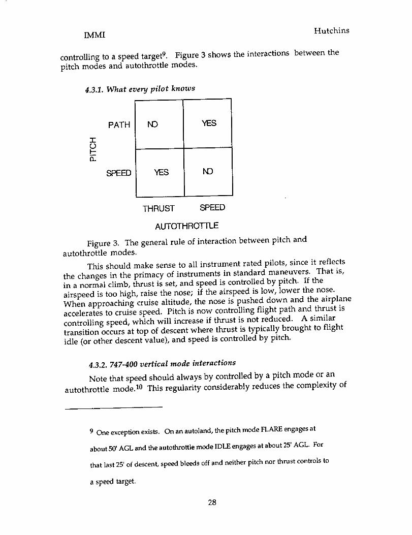
IMMI
controlling to a speed target 9. Figure 3 shows the interactions
pitch modes and autothrottle modes.
Hutchins
between the
4.3.1. What every pilot knows
(.9b-n
PATH
SPEED
N3 YES
YES I,,13
THRUST SPEED
AUTOTHROTII-E
Figure 3. The general rule of interaction between pitch and
autothrottle modes.
This should make sense to all instrument rated pilots, since it reflects
the changes in the primacy of instruments in standard maneuvers. That is,in a normal climb, thrust is set, and speed is controlled by pitch. If the
airspeed is too high, raise the nose; if the airspeed is low, lower the nose.
When approaching cruise altitude, the nose is pushed down and the airplane
accelerates to cruise speed. Pitch is now controlling flight path and thrust is
controlling speed, which will increase if thrust is not reduced. A similartransition occurs at top of descent where thrust is typically brought to flight
idle (or other descent value), and speed is controlled by pitch.
4.3.2. 747-400 vertical mode interactions
Note that speed should always by controlled by a pitch mode or an
autothrottle mode. 10 This regularity considerably reduces the complexity of
9 One exception exists. On an autoland, the pitch mode FLARE engages at
about 50' AGL and the autothrottle mode IDLE engages at about 25' AGL. For
that last 25' of descent, speed bleeds off and neither pitch nor thrust controls to
a speed target.
28

IMMI Hutchins
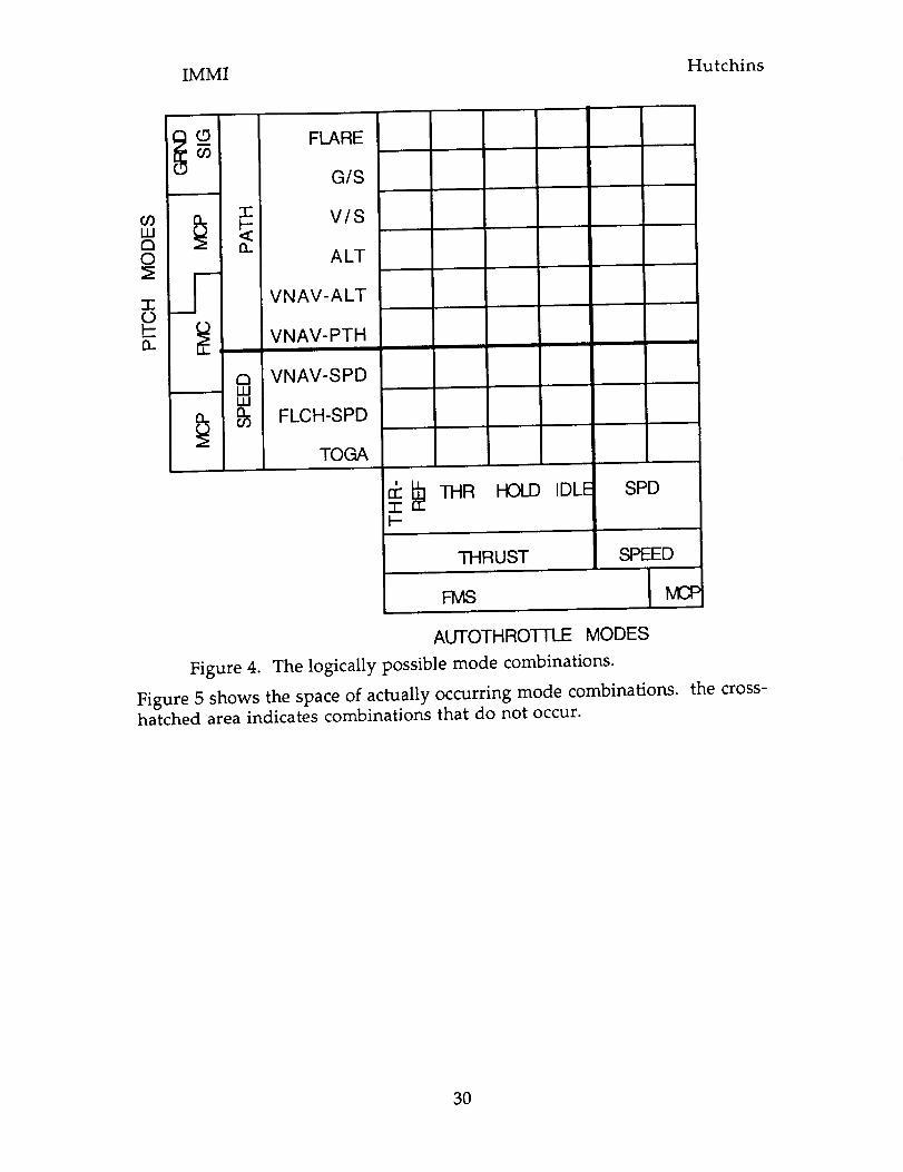
the space of mode combinations. Figure 4 shows the space of possiblecombinations of pitch and autothrottle modes. In this table, the distinctions
among modes are made on the basis of the mode type (pitch or autothrottle),
the controlled parameter (speed or path for pitch modes, speed or thrust for
autothrottle modes), and the source of the target (Mode Control Panel, Flight
Management Computer, or Ground Signal).
10 There is a hidden danger here. It is possible to fly a visual approach in the
747-400 with the autopilot, flight directors, and autothrottles off. If a go
around is required, pushing the go-around buttons will provide go around thrust.
The upward pitching moment caused by the below -wing mounting of the engines
can feel like the TOGA pitch mode acting through the autopilot, even though
the autopilot and pitch modes have not engaged. In this case, the autothrottle
mode controls thrust, but only pilot action with the control column can control
speed. It is possible for a distracted pilot in such a situation to inadvertently
approach a stall condition.
29

IMMI Hutchins
(_ FLAREG/S
09ILlD©
7-0I--13..
-r" V/Sn ALT
J VNAV-ALT
_, VNAV-PTH
VNAV-SPD-- ILl
III
_ FLCH-SPD
I TOGA
_ THR HOLD IDLE"T"I--
THRUST
FMS
SPD
SPEED
I IVLC$
AUTOTH RO3-I-LE MODES
Figure 4. The logically possible mode combinations.
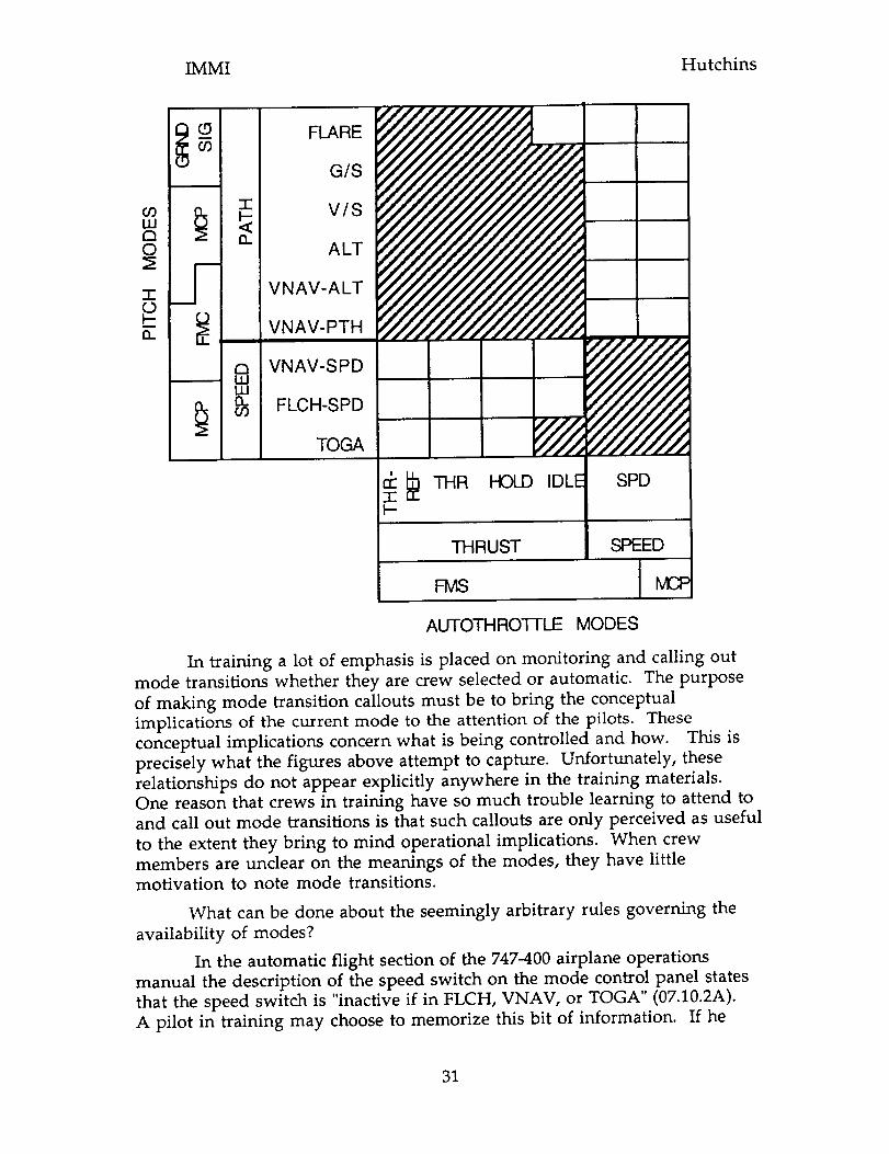
Figure 5 shows the space of actually occurring mode combinations.hatched area indicates combinations that do not occur.
the cross-
3O

IMMI Hutchins
(..9 FLAREO3
G/S
o3 p_ -r V/S
121 _O ALT
T- S VNAV-ALTOI-- VNAV-PTH13..
@ VNAV-SPDnuJ FLCH-SPDO3
TOGA
_ THR HOLD IDLE-i-"I---
SPD
THRUST SPEED
FMS MCF
AUTOTHRO]-FLE MODES
In training a lot of emphasis is placed on monitoring and calling out
mode transitions whether they are crew selected or automatic. The purpose
of making mode transition callouts must be to bring the conceptual
implications of the current mode to the attention of the pilots. These
conceptual implications concern what is being controlled and how. This is
precisely what the figures above attempt to capture. Unfortunately, these
relationships do not appear explicitly anywhere in the training materials.
One reason that crews in training have so much trouble learning to attend to
and call out mode transitions is that such callouts are only perceived as useful
to the extent they bring to mind operational implications. When crew
members are unclear on the meanings of the modes, they have little
motivation to note mode transitions.
What can be done about the seemingly arbitrary rules governing the
availability of modes?
In the automatic flight section of the 747-400 airplane operations
manual the description of the speed switch on the mode control panel states
that the speed switch is "inactive if in FLCH, VNAV, or TOGA" (07.10.2A).
A pilot in training may choose to memorize this bit of information. If he
31

IMMI Hutchins
does not, he is at risk (as reported in section 3.3.9above) of pushing thisbutton while on one of these modes and finding that it does not respond."What's going on?", he might ask. "Why can't I get speed mode?"
The answer is difficult to see in the current system for two reasons,onehaving to do with the design of the mode control panel, the other having todo with the training. The answer to the question is that the speed switchengagesan autothrottle speed mode. FLCH, TO/GA, and VNAV-SPD (pitchmodes) are speed controlling modes. Speedis already being controlled bypitch in thesemodes, so it cannot also be controlled by the autothrottle. Allthe VNAV modes include an automatic speed control function, so SPD modeis not appropriate. But this is hard to seebecause1) the layout of the MCPprovides only implicit hints that the speed switch controls an autothrottlemode rather than a pitch mode (after all, either sort of mode could controlspeed) and 2) the training does not make it clear that autothrottle and pitchmodes have a mutually exclusive relationships with respect to the control ofspeed. If these relationships had been made clear, it would be easy for a pilotreading the manual to know immediately why this switch will be inactivewhen the pitch mode is FLCH, VNAV, or TO/GA. The need to memorizethe fact that SPD is inactive in these modes is eliminated. The behavior ofthe airplane autoflight system becomes meaningful rather than mysterious.
In the description of the IAS/MACH selector, the pilot is told thatwhen the IAS/MACH selector is pushed, the "IAS/MACH window does notblank if SPD, FLCH, or TO/GA mode is active" (07.10.02B). Again, to avoidsurprises in flight, the pilot could either memorize these facts, or understandthe reasonsbehind them. But the underlying conceptions are masked by theorganization of the presentation of information. In this case,no effort hasbeen made to distinguish the autothrottle mode, SPD, from the pitch modes,FLCH and TO/GA. If this had been done, it would be easy to seefrom thediagrams above that these three modes share in common the properties thatthey are modes that control the speed parameter on the basis of a speed targetthat is set on the MCP. The existing instruction and design of the flight deckgive absolutely no explicit representations of the dimensions on which thesethree modes are members of a single conceptual category. If thesedimensions were to be represented to the pilots, it would be obvious why theIAS/MACH window does not blank when the selector knob is pushed whilethese modes are engaged. These are just the modes in which a speed target isalready being set on the MCP. A simple conceptual regularity replaces theneed to memorize what otherwise seemto be unrelated facts.
Similar problems exist in the relationship between the autothrottlemode engaged with the speed switch and the speedmodes engaged by "speedintervention" when the IAS/MACH selector is pushed. The former isexclusively an autothrottle mode. The latter is a "hidden" pitch mode. I sayhidden becausewhen speed intervention is selected on a descent, all theoutward indications are that pitch is controlling path. However, "Duringdescent, when speed intervention is used, the guidance mode essentially
32

IMMI Hutchins
changes to speed on elevator ...." FCTM, p. 3-7. Path is no longer controlled by
the pitch of the airplane. Deviations from path must be controlled with speed
brakes or throttle.
4.4. The conceptual distinctions for vertical navigation.
The componential analysis reveals that the following dimensions and
dimension values are required to make all the distinctions made in vertical
modes for either of the mode naming schemes:
Pitch target type:
Thrust target type:
Target source:
Respect FMC constraints:
Profile shape:
speed, path, vertical speed, attitude
idle, limit, speed
MCP/FCU window, FMC, Nay aid,
Autopilot
Yes, No
Airbus: Level, Up, Down.
Boeing: Constant altitude, ChangingAltitude
Table 4.1. Conceptual distinctions needed to distinguish all modes in
Boeing and Airbus mode naming schemes.
Additional distinctions are needed to actually operate the system.
These include:
Autopilot engagement status:
Mode status
Target priority
Table 4.2. Additional conceptual
engaged, not engaged
engaged, armed, selectable
When there are two targets of the
same type, which one will affect the
flight path? e.g. when window alt and
FMC alt targets disagree
distinctions.
33


IMMI Hutchins
5. The current design
An overview of the IMMI is shown in figure 6. The display consists of
two main areas: a vertical mode manager at the top, and a lateral mode
manager at the bottom.
Figure 6. Overview of the IMMI display. Ready for takeoff. TOGA
pitch and roll engaged, LNAV and VNAV armed.
The lateral mode manager looks and behaves much like the current
generation of lateral navigation displays. However, in accordance with the
design goal to put the means of evaluating the current state of the system,
making changes to the system, and assessing the consequences of changes all
in the same location, the lateral mode manager has been enhanced to
combine the earlier functions of route, data, and weather display with the
new functions of mode annunciation and selection. The lateral mode
manager hardware consists of a lateral situation indicator display and a
heading select knob. Icons on the lateral mode manager show aircraft roll
34


IMMI Hutchins
guidance for heading and lateral path. Icon display state, color, and sizeindicate mode availability, and mode status (engaged, armed, selectable).
Targets values are set by manipulating the hardware select knobs. Themappings of functions from the mode control panel of a Boeing 747-400to theIMMI are shown in appendix 1. The appropriate mode icons appear accordingto the situation of the airplane and the settings of the select knobs. Modes areselectedby touching the icons that represent the desired mode. A completedescription of the controls and indicators on the IMMI display is given inappendix 2.
The vertical mode manager is an all new display which combinesaltitude and speed tapeswith a vertical situation display that depicts thevertical path of the airplane. Mode engagement status is depicted by thepositioning, shape and color of graphical icons. Modes are armed and selectedfor engagement by touching the icon depicting a selectablemode. The verticalmode manager hardware consists of a vertical navigation display, a speedselect knob, an altitude select knob, and a vertical speed selectwheel. Thevertical navigation display contains an airspeed tape, a vertical profile display,an altitude tape, four columns for the display of mode icons. Icons on thevertical mode manager show relationships of aircraft pitch and thrust toairspeed/roach and vertical flight path. Target source (FMCS or crew input)and target value are indicated by the location of the icon with respect toairspeed/mach and altitude tapes.
Autoflight systems' state display and mode selection actions are co-located. In both mode managers, autoflight modes are depicted by icons on aconceptually meaningful graphical display rather than by strings of characters.Target values are set by manipulating hardware knobs.
Although the IMMI includes an airspeed and altitude tapes, it is notintended as a primary flight instrument. Part of the mode management taskis setting targets (speed and path) with respect to other targets, the currentoperating envelope limits, and the current operating parameters. These tapesare provided to make this possible.
5.1. The lateral mode manager
There were three related design goals relating to the lateral mode
management.
1. Make the distinctions among modes more perceptually salient and
conceptually meaningful on the NAV display.
2. Make the active waypoint perceptually more salient on the lateral
navigation display.
3. For all modes, the action taken to select or engage the mode should
somehow bring the operator into contact with easy to process
representations of the specific consequences of engaging that mode.
35


IMMI Hutchins
Figure 6 shows the IMMI display with the aircraft ready for takeoff.
The active waypoint icon is the white circle in front of the airplane labeled
SFO01. It has been increased in size to make it perceptually more salient. It
also always is shown in a color that contrasts with the magenta color of the
FMC computed track line. The active waypoint icon is now a modeannunciator and mode selector. The color of the waypoint icon indicates the
engagement status of the mode. In this case, the white color indicates that
LNAV mode is armed for engagement. When the conditions for engagement
are met (50' of radar altitude) the mode will automatically engage, and the
icon will turn green. Figure 7 shows LNAV engaged with Porte the active
waypoint. When LNAV is selectable, but neither armed or engaged, the icon
appears blue (Figure 12, a&b). In order to engage or arm the mode, the pilot
must find the active waypoint icon and touch it. This makes the spatial
relationships between the airplane, it's current course, and the location of the
active waypoint apparent to the pilot before the mode is engaged. This solves
the "meta-button" problem observed in some engagements of LNAV mode
in the current generation of aircraft.
Figure 7. LNAV engaged, heading bug behind airplane and compass
rose wrapped to keep heading bug visible.
36


IMMI Hutchins
A similar solution has been adopted for the heading selectmode. Theheading selectmode is selectedby touching the heading bug on the NAVdisplay. Just as was the casefor LNAV selection, this makes the spatialrelationship between the airplane's current heading and the selected headingapparent to the pilot before mode engagement. For this to work in allconditions, the heading bug must always be visible on the NAV display. Asthe heading bug moves away from the nose of the airplane, the compass roseon the lateral navigation display expands to always include a wide enough arcto include the heading bug. Figure 7 shows the display with the heading bugnearly behind the airplane. This expansion and contraction of the compassrose satisfies another goal of having the display itself change to indicate thatthe heading bug is going behind the airplane. This additional bit of structurein the display's behavior provides the crew with an additional cue about thelocation of the heading bug.
5.2. The vertical mode manager
Our most general design goal was to build an interface in which the
physical layout and behavior of the displays and controls maps easily onto the
underlying conceptual regularities of the autoflight system. The table below
shows the correspondence of conceptual distinctions underlying the
operation of the vertical component of the autoflight system to perceptual
distinctions in the interface.
Conceptual distinction
Target source: FMS/MCP
Target type: Speed/Path
Control axis: Pitch/Thrust
Mode status:
Engaged/Armed/Selectable/Envelopelimit
Path source: FMS/MCP
Perceptual distinction
Icon location: Between
tapes/Outboard of tapes
Icon location: Adjacent speed tape/
Adjacent altitude tape
Icon shape: Airplane/Engine
Icon color and fill:
Green(solid)/White(solid )/Blue
(outline) / Amber (solid)
Path line color: Magenta/Green
Table 5.1. Correspondence of conceptual distinctions to perceptual
distinctions for vertical mode management.
The vertical path display satisfies the design goals to provide a
graphical representation of the future vertical trajectory of the airplane and to
have a single representation in which all descriptions of flight path are
displayed in such a way that it is easy to determine which will be controlling
in any situation. Figure 8 (Climbing to an engaged altitude below cruise
altitude. The solid green airplane icon on the inboard side of the speed tape
shows that the airplane is climbing in a mode that uses pitch to attain an FMC
specified economy speed target (VNAV-SPD). The solid green engine icon on
37


IMMI Hutchins
the inboard side of the altitude tape shows that the path of the airplane is
controlled by a FMC specified level of engine thrust. The blue outline
airplane icon outside the speed tape shows that a mode in which the airplane
will pitch to an MCP specified speed (FLCH) is available for engagement. The
blue outline airplane icon outside the altitude tape shows that a mode that
will pitch to an MCP specified path (V-SPD) is also available for engagement.
The green horizontal line at FL230 shows that unless a higher altitude is
selected before reaching this altitude, the airplane will level off at this altitude
even though the magenta FMC computed climb path continues up to thecruise altitude of FL330.
Figure 8. Climbing to an engaged altitude target by pitching to FMC
specified Econ speed target.
The extent of the vertical path that is shown depends on the scale
selected on the lateral navigation manager. The vertical path display shows
the same path component as is shown on the lateral navigation manager.
The enroute waypoints are shown along the bottom of the vertical path
display. The "goal-posts" show altitude restrictions specified for the
waypoints. This makes it easy to see if the airplane will meet or violate
38


IMMI Hutchins
altitude restrictions. If the autoflight system predicts that an altitude
restriction will not be met, the goalpost will turn amber.
All and only those modes that can be engaged or armed from the
current operating mode are presented for selection. The display of icons iscontext sensitive so that icons for modes that are not selectable from the
present context are not displayed. Thus, when the airplane levels off at an
intermediate altitude in a climb, no pitch modes are selectable until a new
altitude has been selected. Figure 9 shows the leveloff condition before the
selection of a new target altitude. Figure 7 shows the leveloff after the
selection of a new altitude target, and figure 8 shows the situation after a
climb method has been selected. On the systems currently in use, all mode
select switches are continuously present (as hardware) even though they may
not be selectable. In the IMMI it is easy to see that no vertical modes other
than the currently engaged modes are available for selection.
Figure 9. Level at 10,000'. No other vertical mode icons will appear
until a new altitude target has been set.
Engaged, armed, and selectable modes and their performance targets
(speed, path) are represented explicitly in the color and placement of the
icons. When speed intervention has been selected in any VNAV mode, an
icon indicating return to the FMC computed speed target appears as selectable.
This solves the problem of knowing how to restore the econ-speed target for
VNAV from the speed intervention condition.
39


IMMI Hutchins
Impending uncommanded mode changes are indicated by the engaged
icon turning from solid green to solid amber color before the mode transition.
The most frequently encountered such uncommanded change in normal
operations is the transition from VNAV-PTH descent to VNAV-SPD when
maintaining the path would lead to an overspeed. Figure 10 shows the
VNAV-PTH icon turning amber as the speed approaches Vmax.
Figure 10. Impending uncommanded mode change for envelope
protection. The VNAV-PTH icon turns amber to indicate impending change.
Figure 11. After the uncommanded transition to VNAV-SPD descent.
Notice that the pitch icon has moved from the altitude tape (path) to the
speed tape.
Figure 11 shows the state after the uncommanded change has taken
place. Automatic/conditional mode transitions are not explicitly represented,
but it is always easy to see which mode is coming next. On the vertical path
display, the automatic transition from any climb mode to altitude keeping
mode is shown by the position of the green line. The transition from
40


IMMI Hutchins
localizer armed to engaged on the lateral mode manager (figure 12a and b),
and the transition from glideslope armed to engaged on the vertical are also
easy to anticipate.
Figures 12a &b. The localizer is armed (12a) by touching the localizer
icon. The localizer engages automatically upon localizer capture (12b) and the
icon turns green.
5.3. The airspeed tape
The design goal of associating salient perceptual regularities in the
display with the underlying conceptual regularities extends to the design of
individual components of the displays. The airspeed tape presents an
especially good example. The traditional round-dial airspeed indicator has
some nice cognitive properties (Hutchins, 1995b). The mapping of the
abstract quantity speed onto a fixed extent of space permits pilots to use fast,
robust perceptual processes to do conceptual tasks. Speed bugs partition the
space of speeds into meaningful regions. One of the most important
properties of the airspeed indicator is that its gross physical appearance
changes with speed. This is not true of the current generation of "glass"
airspeed instruments. On these, the gross physical appearance of the display
is the same at all speeds. Pilots often complain that they must read the
number in the box in order to determine their speed. Some have advocated
41


IMMI Hutchins
giving up on airspeed tapes 11. The problem does not lie in the technology,
but in the way it is used. It is possible to build a "glass" tape that has the
cognitive properties found in the round-dial instruments. The speed tape in
the IMMI is an example. The airspeed tape on the IMMI always displays the
entire current operating speed envelope for the airplane. Stall speed is at the
bottom of the tape and Vmo or Mmo is at the top. This speed range is
sensitive to airplane configuration and atmospheric conditions. Contrast this
to the current practice in the 747-400, the A-320, and the MD-11 of showing a
constant 120 knot window around present airspeed.
Figures 13a &b. The airspeed tape showing a slow speed during
approach (13a), and a fast speed in descent (13b).
11 Lovesey, 1992. claims that "tape displays have been introduced into
cockpits at regular intervals (for example: 1925, 1938, 1960s, 1970s). Each time
they are introduced, they are soon found to be inferior to round dials and are
rejected. "
42

IMMI Hutchins
While the present airspeed always appears in the center of the tape inthe current generation tapes, on the IMMI airspeed tape, the present airspeedbox moves to the position on the tape corresponding to the present speed.This means that when the airplane is operating in the slow end of its currentoperating envelope, for example, the airspeed box will be at the bottom of thetape. This movement of the box is a perceptually salient cue for airspeed. Itpermits pilots to judge the speed of the aircraft in functional terms of fast andslow even with the instrument in peripheral vision. Figure 13a and b showthe airspeed tape indicating a low speed on approach and a near overspeedcondition in descent, respectively. Notice that the range of the airspeed scaledepends on the airplane configuration and the atmospheric conditions.
5.4. Conceptual validation:
To ensure that the IMMI could represent all autoflight related actions
and display changes we conducted a careful analysis of a simulated flight. We
identified 102 autoflight related representations and actions in the simulated
flight from PI--IX-LAX. For each event, we mapped out the corresponding
IMMI action or display state.
5.5 New problems introduced by the design.
A small number of new problems are introduced by the IMMI design.
These became most apparent when the IMMI was installed in the Advanced
Concepts Flight Simulator of the CVSRF at NASA Ames. All proposed new
instruments face the problem of cockpit real estate. Where can the device be
placed in the already crowded cockpit. The design of the ACFS includes 5
display screens arrayed in a row across the instrument panel. The IMMI wasinstalled on the center screen. The hardware knobs used to set target values
were installed around the perimeter of the center display screen.
A potentially more serious problem arises from the requirement tohave a touch-screen interface. While it is possible to use touch screens in
aircraft, the designs are limited by two factors. First, the technology of touch
screens is such that there appears to be just enough resolution in the current
generation of techno_,ogy to allow the discrimination of adjacent icons in the
display. It is expectdd that this limitation will be relaxed as the technologymatures. A second limitation concerns the pointing accuracy of an operator,
especially when the airplane may be bouncing in turbulence. The touch
accuracy at arm's length in bumpy conditions is not good, and there is someconcern that a touch interface would become unreliable in turbulence. It is
not known how serious, this problem might actually be. By placing other
fingers on the display frame, it is possible to improve touch accuracy
considerably, even in bumpy conditions.
\
43

IMMI Hutchins
6. Evaluation
The plan for the evaluation of the IMMI has three parts. First, a
comparative cognitive walkthrough for the 747-400 and the IMMI was
performed. Appendix 3 shows sample pages from the analysis. This analysis
led to the production of a set of predictions about the effects of replacing thecurrent interface with an IMMI. Second, the IMMI was installed in the
Advanced Concepts Flight Simulator of the CVSRF at NASA Ames research
center. This required a large software engineering effort because the variables
used by the simulators in the CVSRF are poorly documented and because the
IMMI needed to interface with proprietary code supplied to CVSRF by
airframe manufacturers. Third, a simulated flight scenario was designed to
test the effects of the IMMI compared with the 747-400. Preliminary testing of
the IMMI in the designed scenario was commenced in the summer of 1995. A
comparative study was planned using 747-400 line pilots flying the scenario inboth simulators at the CVSRF. The simulators were taken off-line in the fall
of 1995, and unfortunately, the grant ended before the simulators became
available again.
6.1. IMMI predictions
It is possible to make some predictions regarding the elimination or
reduction of operational errors and the reduction of training time. Here are
five different kinds of predictions about the IMMI.
1. Some errors that have been observed with the current system will be
entirely eliminated because they are made impossible by the new design. For
example, it is not possible with the IMMI to attempt to select a mode that isnot available from the current state of the system. The suppression of icons
depicting modes that cannot be selected in the current context should simplify
the decision rules pilots employ in operating the autoflight system and
should eliminate the now common instances of failed attempts to engage
modes that are not available. This may be operationally important, but it is
not interesting from a theoretical point of view because the prediction does
not make much use of the theory. Perhaps a more interesting case is that one
cannot choose heading select mode without being aware of the current
location of the heading bug. This leads to the prediction that the error of
entering heading select mode while the heading bug is behind the airplane
(producing an undesired turn) will be eliminated.
Note the role of observations of current practices as a baseline against
which we characterize the performance on the new interface.
2. Other classes of error are also expected to occur less frequently. The
unexpected leveloff (e.g. in the Peble 1 departure described in section 3 above)
and other vertical awareness problems should be remedied by the presence of
the vertical path display. Conflicts between performance targets set by crew
44


IMMI Hutchins
and FMCS are explicitly depicted in the graphics of the vertical profile display.This should reduce the frequency of errors due to the autoflight systemtracking a target that the crew is not attending to. This is a bit more interestingfrom the theoretical perspective than the suppression of unselectable modes,but not very much. In this casethe presenceof representations of the rightkind makes the construction of a situation model easier for the pilot. Theconsequenceof the actions are easy to seeaslong as one can interpret thegraphical notation.
3. The frequency of unexpected steep turns to the active waypointwhen rejoining a LNAV route should decrease. This is because the IMMIrequires the pilot to know the position of the active waypoint relative to theairplane before engaging LNAV mode. Putting meaningful content in theaction that engagesthe mode should help fix this problem.
This is the embodiment of a general principle. In the current systemthe internal structure of the actions that selectmodes have only arbitraryrelations to the consequencesof mode selection. In the IMMI, the content ofthe consequencesis built into the selection action. For example, touch theactive waypoint to engage LNAV or touch the heading bug to engage headingselect.
4. The situation with vertical modes is more complex and moreinteresting. With the vertical modes the IMMI employs a theoreticalprinciple that the underlying conceptual regularities in the behavior of thesystem should be reflected in the behavior of the interface itself. This goesback to the Hutchins, Hollan, and Norman (1986)work on directmanipulation interfaces. The basic notion is that the user must create abridge from the structure of a representation to its meaning. We can make iteasy for the user to construct this bridge by providing structure in therepresentation that can be seen as similar to the conceptual structure of thething the representation refers to.
In the IMMI, the conceptually meaningful representation of modesmirrors the underlying regularities of the autoflight system. This shouldreduce the apparent complexity of the autoflight system, thereby promotingsafer, more efficient use of the autoflight system. It should also reduce theamount of training required to prepare pilots to fly the airplane, and improvethe quality of actual flight experience asa context for learning. Thisrepresentation also permits flight crews to link perceptual routines for
parsing the display to the underlying conceptual regularities.
This problem exists at all levels of organization of the system. Thus
the static shapes of the icons should suggest the things they are intended to
represent. But also, the behaviors of the icons should suggest the behaviors
of the things they represent. The IMMI uses space and color to encode
conceptual features of autoflight that are masked in the current interface. For
example, icons depicting FMC targets are inside the tapes - adjacent to the
FMC computed path. Icons depicting pilot specified targets are outside the
45

IMMI Hutchins
tapes. The icons are of only two types: pitch and thrust (distinguished bymeaningful shapes) and they are associatedwith only two kinds of targets(speed and vertical path). The association of performance target with acontrol axis is indicated by the spatial adjacency of the icon(control axis) withone tape or another (performance target).
The prediction from this is that it will be easier for pilots to 1) seeandunderstand what the system is doing. 2) operate the system, 3) learn to use thesystem.
5, Another classof predictions concerns the distribution of placeswhere pilots must attend. MCP, FMA, MCDU, PFD in order to do the job. Co-location of mode state depiction and mode selection apparatus provides forthe composition, execution and evaluation of mode management actions allin the same place. This should reduce the frequency of mode selection errorsdue to crew failure to note flight mode annunciator changes.See (Palmer,1994)for a casein which an altitude capture was killed by a mode selection ina recently changed mode configuration.
All of these predictions have the character of noticing a problem in thecurrent interface, characterizing the situations in terms of a cognitive theory(is it a memory problem, a reasoning problem, an activation error, etc.) andthen exploring design alternatives that, when characterized in terns of thetheory, do not generate the earlier observed errors.
6.2. Flight test scenario
A simulated flight from SFO to LAX was designed to test the IMMI.
The simulated flight includes operational contexts which have been observed
in line operations to lead to various classes of mode management problems.
The ATC script for the scenario is shown in Appendix 4. A description of the
flight, the interventions, and the expected consequences in terms of mode
management are given in Appendix 5.
46

IMMI Hutchins
7. Conclusions
The Integrated Mode Management Interface is a graphical user
interface to the autoflight mode management functions of state-of-the-art
airline cockpits. It is based on the design principle that the perceptual
distinctions available in the appearance and behavior of the interface itself
should mirror the conceptual distinctions made in the structure and function
of the underlying autoflight system.
More work could surely be done on the design of the icons and the
graphics. It may well be that pilots would prefer a different sort of icon set to
represent the distinction between pitch and thrust modes, for example. The
current design also seems visually busy. A cleaner, simpler design with a
lower spatial frequency would probably be an improvement. It may even be
the case that a different conceptual model would better capture the
underlying distinctions that pilots need to make to reason about and control
the autoflight system. Captain Jim Irving has suggested that _the display
should also represent the energy situation of the airplane 12. This would be
especially important in an airplane like the High Speed Civil Transport.
Whatever the refinements that are made, I am confident that the
principle of building an interface that provides a perceptual basis for
conceptual process is correct. The IMMI is an attempt to explore the uses of
that principle in the domain of autoflight mode management.
Acknowledgments:
This research was supported by the National Aeronautics and Space
Administration under grant NCC 2-591. Important guidance was provided by
Ev Palmer, Mike Feary, and Nancy Smith at NASA Ames. Special thanks to
Captain Jim Irving (UAL) for insightful criticism and great ideas at all phases
of the development of the system. Thanks to Peter Polson and Sharon Irving
at University of Colorado for encouragement and criticism. Capt. Alejandro
P6rez Chav6z (Aeromexico), and Captain Joe Hall (USAir) reviewed an early
version of the IMMI and provided useful criticism. The crew of the NASA
Ames CVSRF provided support for the installation of the IMMI in the ACFS.
The members of the Distributed Cognition lab at UCSD turned the design
ideas into a working prototype. Nick Flor, Randy Gobbel, Brian Hazlehurst,
and I did the programming. Christine Halverson assisted with design
decisions and did most of the concept validation with the simulator
videotapes. Mike McCoyd wrote a users manual and supported the analysis
of mode logic. Boeing Commercial Airplane group (Curt Graeber) provided
me with the complete transition training course for the 747-400. Douglas
12 Jim Irving, personal communication, August 1994 and May, 1995.
47


IMMI Hutchins
Aircraft (through the help of William Corwin) allowed me to attend MD-80
ground school. I am grateful to American West Airlines (especially, Beth
Lyall) for the full A-320 ground school.
48


IMMI Hutchins
8. References
Agar, M. (1980) The professional stranger. New York: Academic Press.
Agar, M. (1986) Speaking of ethnography. Beverly Hills: Sage Publications.
Clark, A. (in press) Being There: putting brain, body, and world together
again. Cambridge, MA: MIT Press.
D'Andrade, R. (1995). The development of cognitive anthropology. New
York: Cambridge University Press.
Goodenough, W. 1956. Componential analysis and the study of meaning.
Language, 32: 195-216.
Holland, D. and Quinn, N. (1987). Cultural models in language and thought.
New York: Cambridge University Press.
Hutchins, E. (1980). Culture and Inference. Cambridge, MA: Harvard U. Press.
Hutchins, E. (1995a) Cognition in the Wild. Cambridge, MA: MIT Press.
Hutchins, E. (1995b). How a cockpit remembers its speeds. Cognitive Science,
19:3, 265-288.
Hutchins, E. (in prep) Cognitive Artifacts. in R. Wilson and F. Keil (Eds.) The
MIT Encyclopedia of Cognitive Science. Cambridge, MA: MIT Press.
Hutchins, E., Hollan, J. D., & Norman, D. A. (1985). Direct manipulation
interfaces. Human-Computer Interaction, 1, 311-338.
Lenorovitz, Jeffrey. (1992). "Airbus stresses cockpit management, coordination
in transition training" Aviation Week and Space Technology, Vol 136,
No. 6. Feb. 10, 1992. pp. 29-30
Lovesey, E. (1992). Displays vacillate with fashion. Flight International, 12-18
August, 1992.
Norman, D. (1993) Things that make us Smart. New York: Addison Wesley.
Palmer, E. A., E. L. Hutchins, R. A. Ritter, I. van Cleemput, (1993, October)Altitude deviations: breakdowns of an error tolerant system. NASA
Technical Memorandum 108788. National Aeronautics and Space
Administration, Ames Research Center, Moffett Field, CA.
Palmer, (1994) et al "OOPs it didn't arm." Paper presented at ASA contractors
meeting. NASA Ames, August, 1994.
Polson, P. Cognitive Walkthroughs.
Romney and Dandrade, 1964. Cognitive aspects of English kin terms.
American Anthropologist. 68:3:2 146-170.
49


IMMI Hutchins
Sarter & Woods (1994)Pilot interaction with cockpit automation An
experimental study of pilots' mental awareness of the flight
management system (FMS). The International Journal of Aviation
Psychology. 4(1), 1-28.
Vakil, S. S., Midkiff, A.H., and Hansman, R.J. (1996) Development and
evaluation of an electronic vertical situation display. MIT Aeronautical
systems Lab report ASL-96-2. (June, 1996).
Weiner, Earl. (1989). Human factors of advanced technology ("glass cockpit")
transport aircraft (NASA Contractor Report No 177528). NASA AmesResearch Center.
Werner, O Schoepfle, M, (1987) Systematic Fieldwork. Beverly Hills: SagePublications.
50


Appendix 1

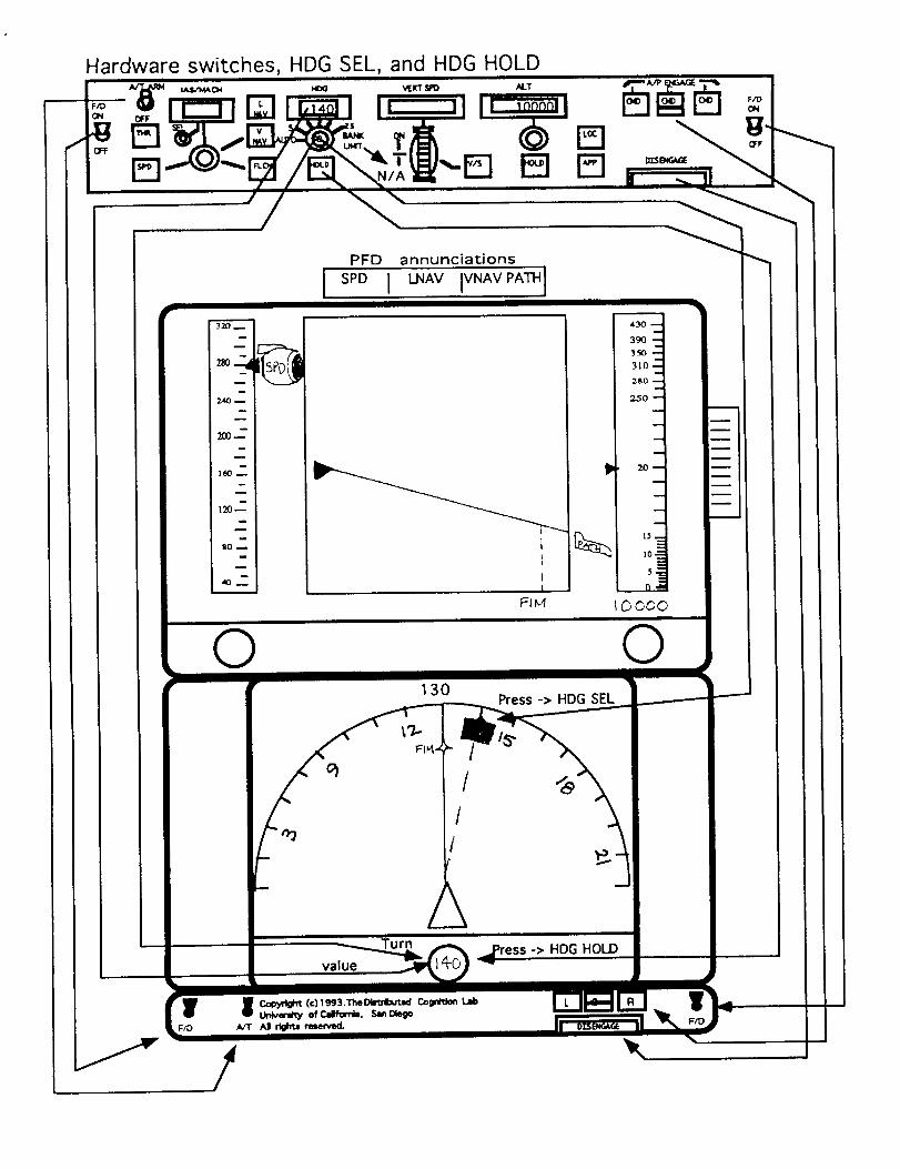
i i E_=a_. _
m i w
w i
24OD I
n im i
m i
200--I
i i
ll_m !
- !
i
l_0_
gOI
/
annunciations
I _v iVNAV_i
130
I/1I
2x
--->__t1il
P
Press -> HDG SEL
F/D
43O --'4,.4
390 --.I
3_,o ---I310 -_
260-,-s
250 "'I
2D =--_
15,__
Z
n,-
0ooo
©
_press -> HDG HOLD


Restriction
N/A
Aw when in
VNAVonG/S. Appearsasblue engine icon in themanual speed column
clearance from ATC
PFD annunciations
SPD j LNAV IVNAVALTI
when iconis green
©180
Iq 000
O
.,el-
F/D F/D

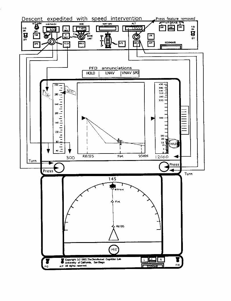
Descent expedited with speed intervention rPress feature removed
D_-et e _l_!-e_m ,,o-,,
Turn
r
_o-,d
24o_-
200--
m
I_o"m
300
Presl_s@
PFD annunciations
1 I L1 I I
P
v
145
/- iX
390 '-"N
31o --
2BO --i
350
300
:250--
ZO_e _
, 1$i
12ooo 41- --
m
m
Turn
II
F/D

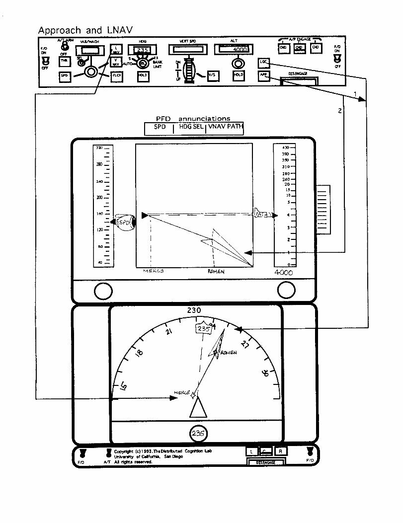
Approach and LNAVi
PFD annunciations
230
F/D F/D


App d 2en ix


1st pass: 6/25/93rev: 7/7/93
fL r
Document: panel standards
date printed:7/7/93
J
TOp Panel - vertical display
a. Speed Tape.
Displays the appropriate range of speeds for the flight's current operation
envelope. (As determined by weight and altitude.)
b. Vertical profile display.
Displays the vertical component of the FMC entered route. Also displays
manual adjustments and overrides.
c. Altitude Tape.
Always displays the complete range of altitudes for the directic_n of cruise.
Includes a sliding virtual window that covers half of the tape in order to
provide greater resolution for the 10000 feet surrounding the current
altitude. See w for a more complete description.
d. leon Column for manual speed changes.
All icons for manually adjusted speeds will appear in this column.
e. leon Column for FMC speed changes.
All icons for either FMC controlled speeds, or FMC speed editing, will
appear in this column.
f. leon Column for FMC altitude changes.
All icons for FMC controlled altitudes will appear in this column. In
general, all thrust-to target altitudes will be here, since the FMC controls
thrust. (But there are exceptions, such as altitude capture or VNAV-
PATH.) Pitch-to targets which are FMC entered altitude restrictions will
also be here, even if a different window altitude target exists. Once the
altitude target in the altitude window is captured however it will appear
in the outside column, g. (see below).
g. leon Column for manual altitude changes.
All icons for manually commanded altitudes will appear in this column,
when captured. Since most altitude targets in the altitude window,
although manually selected, are achieved via the FMC, their icons
appear on the inside of the tape. At capture however their manual
selection is recognized. Vertical speed icons will always go in this
column, since they are completely manually determined. Thrust-to
icons for A/T HOLD in either TO roll or descent will also go here, since


1st pass: 6/'25/93rev: 7/7/93
Document: panel standards
date printed:7/7/93
they indicate that if the pilot manually adjust the throttles the throttles
will remain in place at the manual adjustment.
h. Pitch to target leon.
Engaged icons should be LARGER than armed or selectable icons.
Color: white Condition: armed.
This means that the icon is controlled by some other action, usually via the
FMC. When the appropriate conditions are met the icon will
automatically engage.
Color: blue Condition: selectable
This means that the icon represents an option that can be chosen. Touching
the icon will engage that option if the conditions for engagement are met
(which will usually be the case). Otherwise the icon will go to armed.
(EX. localizer, G/S icons which appear on the lateral and vertical
displays respectively.)
Color: green Condition: engaged
This means that this represents what is currently providing command
guidance.
Shown are a selectable pitch-to-manual speed in the far left column, a
selectable FMC computed pitch-to-ECON speed in the next column and
an engaged pitch-to-path for the captured altitude in the far right
column.
i. Thrust to target icon.
Engaged icons should be LARGER than armed or selectable icons. Note
definitions of the conditions are the same as in h. above.
Color: white Condition: armed.
Color: blue Condition: selectable
Color: green Condition: engaged
Shown are an engaged thrust-to-speed, selected by speed intervention in the
inside left column and an armed thrust-to-path/altitude in the inside
right column.
J. Manual speed window.
Color: blue Condition: selectable
This shows the current speed of the aircraft and is associated with the pitch-
to-speed icon in the manual column. The selectability is actually of the
associated icon.


1stpass:6/25/93rev:7/7/93
Document:panelstandards
dateprinted:7/7/93
Color: green Condition: engaged.
Once the appropriate manual icon is selected that icon and this window
changes to green to show that t.his is the engaged option.
k. FMC edited speed window.
Color: magenta.
The value in this window is always magenta so that it is clear that this is a
target that edits the speed in the FMC. The airplane will follow the
magenta path on the vertical profile display at the specified speed if
possible.
I. Altitude window
Always displays the manually set altitude target, usually the last ATC
cleared altitude.
Color: green. Condition: engaged.
This means that this is the current altitude target being flown to. It is also
represented on the vertical display by a green line, n.
Color: blue Condition: selectable
Moving the knob changes the value in the altitude window and moves a
line on the vertical display which represents the new altitude target.
This line, m., and the number in the window, are both blue. This
corresponds to a selectable pitch icon representing choices of how to
meet that altitude target. When the desired icon is selected then the
icon, the new altitude target in the altitude window, and it's associated
line all turn green.
m. New altitude target.
Color: blue Condition: selectable
Color: green. Condition: engaged.
When a new altitude target is selected, if the previous altitude is captured,
then a dashed blue line appears on the vertical display. As the altitude
knob is adjusted, changing the number in the altitude window, this line
moves to the appropriate spot on the display. The new altitude is
engaged by touching the appropriate icon corresponding to the desired
method of reaching the target altitude. Engaging the icon will change
the line to green for engaged. The line for a previously captured altitude
will disappear.
3


1stpass:6/25/93rev:7/"//93
Document:panelstandards
dateprinted:7/7/93
n. Captured altitude or engaged altitude target.
Color: green Condition: engaged.
See m.
o. Current FMC route - vertical component.
Color: magenta.
Shows the vertical portion of the active route entered in the FMC that the
auto pilot will fly if A/P engaged and VNAV is the active mode. In this
case the start of the path in front of the nose of the aircraft indicates the
top-of-descent.
p. Alternate path
Color: blue. Condition: selectable
Color: green Condition: engaged.
Shows the vertical portion of the manual choice for ascent or descent to a
different altitude when at a captured altitude, IF that path will be
different from the FMC computed path. In this case the diagram
assumes that the descent path associated with the manual pitch-to-speed
icon is different than the FMC computed path. Note that paths
associated with manual speed targets circumvent the FMC path and
therefore any FMC known altitude restrictions.
If the manual pitch-to-speed icon is selected and engaged then this path will
change to green. The FMC computed path will remain in magenta on
the display.
Note: behavior of lines representing paths and altitudes
Magenta paths are always FMC controlled and solid lines.
Captured altitudes are represented by solid green lines. Engaged altitude
targets that have not been reached are represented by dashed green lines.
If this altitude target will cause the aircraft to level off then the portion of
the line that continues from the path will be solid. Eg. on the diagram if
line m became the engaged altitude target then the portion of m near the
letter p would change to a solid line.
Alternate paths, other than FMC computed paths are solid lines shown in
blue when selectable and green when engaged.
q. Crossing restriction.
Color: magenta. Condition: engaged.
Color: amber. Condition: warning.
4


1stpass: 6/'25/93rev: 7/7/93
Document: panel standards
date printed:7/7/93
Direction of arrow indicates "cross' at or above" versus "cross at or below". If
no arrow then it is a "cross at" restriction. Indicated in magenta to show
a part of the FMC route. If one changes to amber it is a warning that the
current performance of the aircraft may not meet that restriction. The
first restriction that may affect the FMC path will have a horizontal
dashed magenta line lining up with the altitude tape. For example, the
FMC path shown here will easily make both restrictions at CZI, but the
restriction to cross ROCKY @ 10000 will force the aircraft to level out, so
there is a dashed magenta line.
r. active waypoint.
Color: green Condition: engaged.
Color: white Condition: armed.
Color: blue Condition: selectable.
Corresponds to the active waypoint on the lateral display. Green and
engaged refers to the engagement of LNAV. If LNAV is not engaged
because HDG-SEL is engaged, then the active waypoint is blue. If LNAV
is not engaged because LNAV is armed before TO, but not engaged then
the active waypoint is white.
Note: Waypoint identifiers are shown below the line delimiting the vertical
display. Waypoint identifiers are assumed to be either 3-letter VOR
identifiers, 5-letter intersection names, lat-long designators or fix/radial
distances (eg. BLH275/075 where BLH is the VOR, 275 is the radial and
075 is the DME distance).
s. inactive waypoint(s)
Color: magenta.
Corresponds to the inactive waypoint(s) showing on the lateral display.
Regardless of whether LNAV is or is not engaged the inactive waypoints
will always show in magenta.
Note: route mismatches on approach
Color: amber. Condition: warning.
If during approach a route in the FMC does not match the displayed glide
slope (G/S) for the runway then the waypoint identifiers will appear in
amber as a warning that the displayed waypoints and their restrictions
are not for the G/S displayed.

1stpass:6/25/93rev:7/7/93
Document:panelstandards
dateprinted:7/7/93
t. Speed knob.
To manually adjust speed.
If the aircraft has captured an altitude and a new altitude target is selected,
then the current speed will appear in the manual speed window and an
associated pitch-to-speed icon will appear in the far left icon column. In
this case moving the knob will adjust the speed, as well as moving the
appropriate icon in the manual column.
If the aircraft has captured an altitude, but no new altitude target is selected,
then touching the speed knob will cause the current speed to appear in
blue in the manual speed window. An associated pitch-to-speed icon
will appear in the far left icon column. Moving will then change the
speed that appears in that window, as well as moving the appropriate
icon in the manual column.
Pushing the knob is required for speed intervention. This will cause the
current speed to appear in magenta in the FMC speed editing window.
An associated pitch-to-speed icon will appear in the FMC speed icon
column. Moving will then change the speed that appears in that
window, as well as moving the appropriate icon in the FMC column.
u. Altitude knob.
The altitude knob is used to manually adjust the altitude target. The current
altitude target always appears until a new altitude target is entered. This
knob changes the value in the window, as well as moves the appropriate
icon in the FMC or manual column, and the altitude target line on the
vertical profile display.
v. Vertical speed wheel
Touching this wheel causes a pitch-to-path icon to appear in the manual
altitude icon column at the current rate of vertical change. Note: here, at
level flight the appropriate icon would show 0 for no rate of vertical
change.
Moving the wheel will change the rate of descent or ascent. The icon will
appear next to the altitude target and the value of vertical rate will alter
inside the icon as the wheel is moved.
w. Altitude resolution window
The nearest 10000 feet to the aircraft are displayed at a higher resolution
than the rest of the altitudes. This virtual window moves with the
6


1stpass:6/25/93rev:7/7/93
Document:panelstandards
dateprinted:7/'//93
aircraft. In the scenarios the window is shifted when the aircraft is in the
middle of the range. Ideally in implementation the window shifts
continuously.
During approach the resolution shifts from a tick mark every 1000 feet to a
tick mark every 500 feet.
x. Aircraft
Color: white. Position on the vertical display indicates the aircraft altitude.
y. Glide Slope
NOT SHOWN-
Glide slope(G/S) symbol as shown on approach plates. When the runway is
entered in the FMC the G/S symbol will appear on the appropriate place
on the route in blue to show that it is selectable.
When touched, the blue icon changes to white to show that the G/S is
armed for capture. When the G/S signal is captured the icon
automatically changes to green to show engaged. When engaged this
signal controls the vertical guidance of the aircraft, so horizontal lines
associated with altitude targets disappear from the display. Note: at G/S
capture the altitude window can be reset to show the missed approach
altitude.
Bottom Panel- Lateral display
a. Heading bug knob.
Moving the knob moves the position of the heading bug in the direction of
movement.
b. Aircraft Indicator.
Color: white. Indicates the aircraft position and direction of flight.
c. FMC route.
Color: white Condition: armed.
Color: magenta. Condition: engaged.
Shows the active route entered in the FMC that the auto pilot will fly if A/P
is engaged and LNAV is the engaged roll mode. Waypoints other than
the active one are in the same color as the route. The extent of the
laterally displayed route corresponds to the extent of the vertically
displayed route.

1stpass:6/25/93rev:7/7/93
Document:panelstandards
dateprinted:7/7/93
d. Active waypoint.
Color: white Condition: armed.
Color: green. Condition: engaged.
Color: blue Condition: selectable
Shows the immediate target waypoint for the FMC. Distinctions between
armed, selectable, and engaged correspond to that described for the
vertical display.
e. Heading bug line.
Color: white, green
Dashed line that extends from the nose of the aircraft indicator to the
current position of the heading bug.
If the heading bug is selected then this line will change to green.
f. Heading bug.
Color: blue Condition: selectable
Color: green. Condition: engaged.
When green the heading bug indicates in HDG-SEL mode. Changing the
bug position will result in changes in aircraft position.
When blue the heading bug shows that HDG-SEL is available and selectable.
In this mode moving the heading bug does not alter the aircraft's course.
g. Current heading/track indicator.
Color: white.
Always indicates the current heading or ground track being flown. Which
one is determined by the display mode the lateral display is in.
h. Compass rose
Color: white
Note: this rose is not an accurate 180 degrees. Rose can be displayed in any
of the legitimate display modes for the lateral display.
i. Ground track indicator.
NOT SHOWN-
Straight green line with arrow at the end where meets the compass rose.
Color: green Appears only during takeoff to indicate the ground track
aircraft is flying for roll guidance during TOGA mode.
J. Localizer
NOT SHOWN-


Istpass:6/25/93rev:7/7/93
Document:panelstandards
dateprinted:7/7/93
Localizer symbol as shown on approach plates. When the runway is
entered in the FMC the localizer symbol will appear on the appropriate
place on the route in blue to show that it is selectable.
When touched, the blue icon changes to white to show that the localizer is
armed for capture. When the localizer signal is captu.red the icon
automatically changes to green to show engaged. When engaged this
signal control the lateral guidance of the aircraft so if the aircraft was
previously in heading select it is not any longer. Note: at localizer
capture the heading bug automatically resets to the localizer inbound
course.
HARDWARE
Duplicates the necessary hardware switches.
a. Flight Director toggle switch
Up is the on position, down is the off position. These switches must be
manually flipped on in order to provide FMC generated flight director
information to the primary flight displays.
b. Auto Throttle toggle switch
Up is the on position, down is the off position. When manually flipped this
turns the auto-throttles (A/T) on and off. A/T can also be disconnected
from buttons on the throttles themselves. When disconnected the
toggle-switch should reset to the off position.
c. Auto Pilot Push buttons.
Pushing these buttons engages the auto pilot (A/P). Each button represents
one of three available A/Ps. Usually the aircraft is flown with the Center
(C) A/P engaged. Engaging the A/P means that the FMC computed
commands are being directed to control surfaces to fly the aircraft,
depending on the engaged modes. When an autopilot is engaged the
button will change to green.
9


Appendix 3


0
0
Z0Z
! ._. 3
0 "_-a ,-_,-4- 0
Cb
-- (D_D -a,4- ridCb Cb_) ce
_. N" _
__.
g =-
_ .._"tO


I-"


_ _._-
o5. g--_,. _ _.
_ _'-_
.p,'_g_
g,
g
N
gg


Oc,
O3¢'Boe
r'_
Lc_
tBo..
o_°0_
3
_>
o0o
"O
O<.O.._B60
(.QCO..
O
c'1-O
O
_)_°
tB
Z_
O.._0
_O
Z_O..
Ocl.
3
_D
O..--°
O.. "_--° ,-_
O <
_0 0_0 C
o 3
r-"o
N
O OO_ D
C
D
up"9
F-O
_D--°N
3O
UD
tO_D
)> >
D _ O
O ?4" _"e-_ r- f-
I'D -_
"* _t cr
_ 23.'-_| --, __.
e4. c_ _0 ¢B 0C _ _O- n)
o"_ Z
C __. ,'-4-
-, g
O_"
r--o
--°N
--°f_0
C
O-
C
0cf_
--°
O
O
00t0
3
3OO__1)


_D_D
0
D"
tD
0
>"1"1
_ 0
1-
0
D
oS_o _°o__ _
.r_ _-_ m o0 _.o -n'_ _ t:r" ,
_.__o• _n co O. "ID! ""i
0 _ _ "I" ' _D0
-0 0
-- 00
Z0ZrT1
o° __,_ _.._,
° _.o_H-
o
,'4" ZIZ
t_ CD
CO "_
¢D _0C_ _"
0 -x
Q. co--. _ 0
r-P
¢D0 -x
_D co
--%
n- m
o
n- m0 O_
o_ _-
0 --
0
_ -_.
--. 0
I°

0
0
3ii
"17c_
"0
0<
Q_
Q_
0
0
3mo
"7
--°
--0
C
{I) __°
0--°
77 0
x
"17 0 0
zz o0 :_
0
oR
,=I=i
o


0e-cI"
0
3ii
m
o-_ <
0 0_
E
E o_
E C)
C¢I O_0
D_D
_0.._"
_ E0 D
Q.
0
¢-t
fD
C)
03I'D
_. "H
D 0c_
o O:N°2 __"
0 _
-r _n


0 __ZC: _ 0
,'t" _ _" "rcD0 _< _ -"
I'D
r'-0 --°
_> • _
"1:3 r'-__ 0 m
Q- _ -,
rD
n _
_ 12r
0 tQ
o
o
_ o_o
:3-" 0
_ 0
...h
0
U')
0
23"
0
rn
c 3:3>23 _
"7"
I
t_mr'-
(._
>
'-'_z
(1) 0 12r
¢-b
('_ i-
0
>>< --
z0
E_
O.c)
0
"7"C_G')
U_m
zOZrn
o= _o_
--" (/) (n0 _ ,-I-
c_
°_o_
_'__g_0
,..i. 0
Z c_.,-, >._" < B
0 __ 5"r- ¢_"0 _
B 5"_ ta
m
(.D
N _
I°


0 _''_.7C CI. CD
"4" _D" -<"0 _ c"3 _ m
o 0
u
0
0
C_°
0
__."13
I'D
¢-'1"
0...%
0
0
0
33Q.
0C
m
co
"17
!
('D
r"Z
<
r-Z
<
0 I"71 _. _
r- "17Zo _-__:; _o
:D'--. ¢'_._--. _ _.
r_ 3 __._0 --- _ _
_r_ 0
_ .._ _ e- CD
_ _ _. ::r" _._3 0_ _. .._ r-_"o o Z_
_o _ <0
n _o _'3LO 0
_ CD
"_ 13-
_<
¢'D
5" _
_'1 _--'_ ..n _
c 3__. 3
0
0
F" "4"Z _
< o
_ I'D Z
!
_ ,_. v_ ' CD
---" _ o" o" -o_0 C_ _. ,-4,
°o_, --9_ _.0 tD _ _
_o_. _. & _ _
I'_ _no°Sb_o
r-
oct-,I-I'D
I'D
o
0-,!
Ri

5"_'_
o_o 5" _"_'_ O- 0-
I[°_ --_ -N"0 _
8 g
cr _
g
gg

0rrl.
rJo3ma
rrl
cDQ_
0_
3
"1"1
,-.$
0<
c"_°
r_CD
c)
0
r.,i-
CD
0
0
N
CD
r__°
c_
0
3
m,
CD
Q.._°
CQ
0_ CD
_30
"11
-rl
!
CDCD
I--0
I--0r)
NCD
0r_
CD
(1)
-rl
_ _ 0
o_ m
_m__.
0 "
o N30
Z0
0
Oct"
_ 0
r-0-"c-_o
_ 0
--,, _-0¸:::3
3_
0t--
r-o
e-
o
o
330 _
0
0

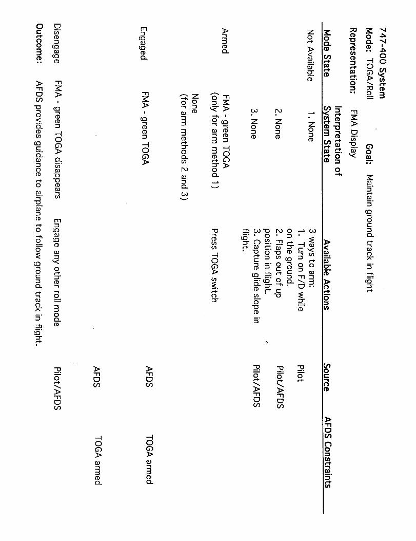
0 C_r-. _.
0 t.O3
3>
C30'3
0_°
0..
tr_
_°
O_
o
r-l-
0
153_°
"0
0
0
0
CO
0C
O_
ox-_°
_.
CO
"I"I
3>!
tO
a)
0d3_>
c_
"0"(D
m
co
cb
_o
0
.-%
0
30O_CD
0
_>"11C_Q_
_>"I"IC_£0
0u")
3("b
I-r'l
(.Q
r_3cl)
i I:_ t'b
o_) "m
('I)
o o 3 _o.. _ 0
IX.) 0
.._a
O0
3>"17C3
..q0
3
(I)
0_
0
3>0')
0
O0 Po
Z 70 0
-_ 00"0 hO 0 -_ O0
_:_'" 0 ' _ •
° _ o°
(I)
:3
"_ -o _-q0 0 0
"_ "7"IC_ C_
o o _ _&
__._'
• _ >
.g
g,
o
_°
_°
"'l
0C
O_
"--h
z:r
O_
o
oon
B_


0e-el.00
3tDin
>"rlc_
"0
0<_°
r_
c0
(Q(-Q_
0CDe-t-
O
0
_°
"D
CD
-1_C_Go
<
CD
e-l-
o_°
CD
"ICO
"1CD
CD<CD
--'Z0r--i-
"1- cD
G')"1"0O.
(/)
<
_°
O-CDm_
cO
el-
m >>
CO _ "<CD O- U_
z0zi-n


OEm.-4.
O
3
"I-%tc_
O_C
E
¢,%
O
O
m°
E
_.
¢--
el)
m
(.Q
G_¢l)
_°
m
x
('D
<
(._
z0
f_
---tr-
0
"1"1
o
o
X
ca
Q_
Z0¢-_
<
[:r
z0-!
x
O
f_
('_ _
0
Z0
('D
'_0
I-
o
m°
_°
r"
0
r'_
(.-
a

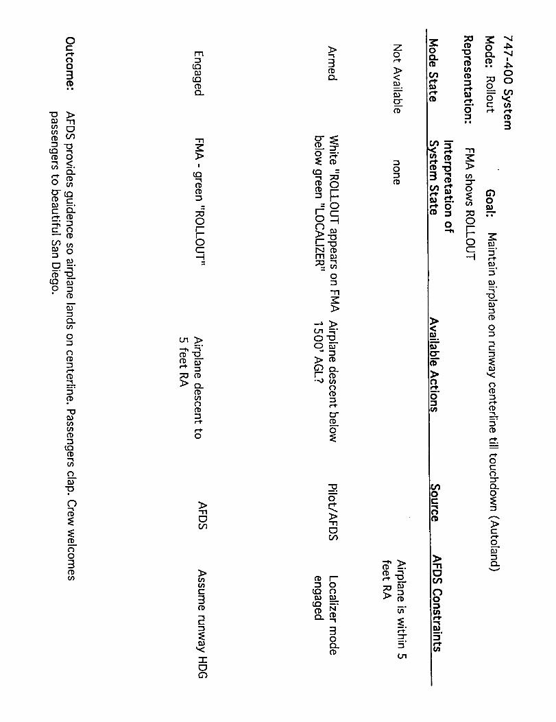
0i-i-I*
0
3ii
I_ "1'1
0'}('b O_-i "0
0
1:1.
0
Er_l'b r-_ _o
(.-- _
E _
_ O
__._"
_ EO _
O.
O
_,
"0
tO
"O
O3
m
_3
'-m
I
Or-"rOC--!
_°
_ E
>o.
O
-rl
>
c-
3
(-
212
>
3
_::rO N-"
m O_ r_ r-
-Or- c0--1t_
r-._N ('_
O
U1 --N"O'_o_
" 23
r'- O
O
"13
O
r0
N
3O
('b
o o _ _
< _ o_°cr ft._- o _
P.
o I__ >= .g
(1) _°
_°
D-
o O•._ r
r-"0c 5"
_°
r-
_°
t :Or'-_ oa _
c-
O_.)
g v
g


dD
4_
4:_
d_

(3C_
W..=a
4_

"el
0
0
<Z><


"el
C_
4_
4_
0
0
r_
"el
o
0_
.£::_
o
0-QcD
o
0_"1
0
,-3
o
mo
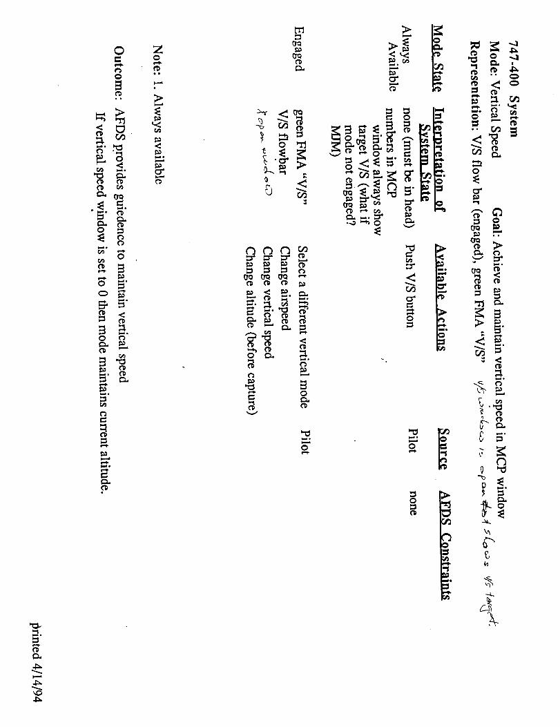
CD
4_
0
0
0
0r_
b.._.o0 +'+
0
CD
N
Z0
ee
>
c_t_
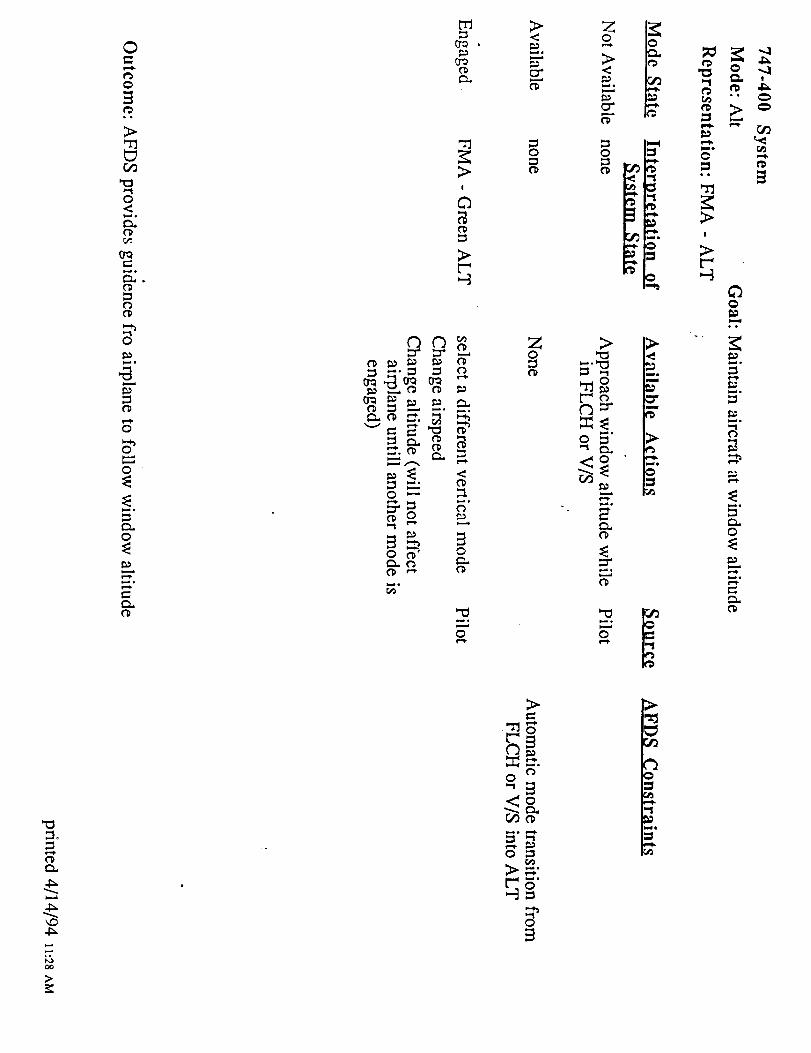
"el
4_
CC,
>
0
0
>
r._
"el,.,.,io
i,,,,i 0
0"_
l,-,,J •
0
l-i,
_3
0
O-
l,-,J •
0
O_
0
0 0
0
>
0
0
_-" 0=
g_
>
?
_o

4_
3_
>
o
o o

4_
4:_

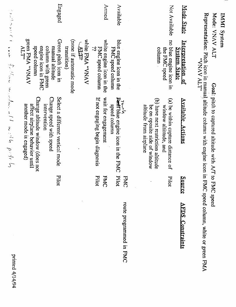
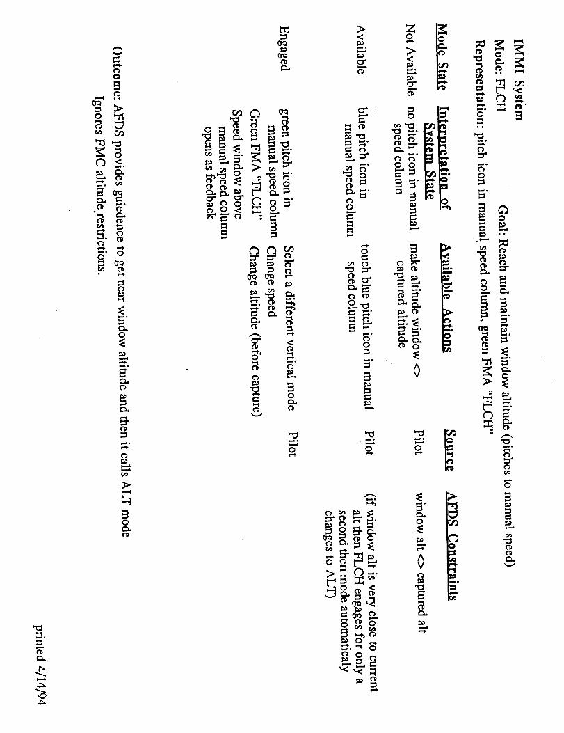
4_
0 0 0
0

0
0
ol
>
O_
p--_o
0
O_
0
0
i,,_o
0
_ ,-_ °o
"" ::r'0 "_ ,-..
_. ,"* 0
mo
mo
0
oo
Cl
t_
>
0
0
00>

O
0
**
o0b.-.
0
_,.d*
0 _
t__" ,..
0
t_
0,,,_.
Z
.o
t_
C_
0
f_
0
?
"0
4_
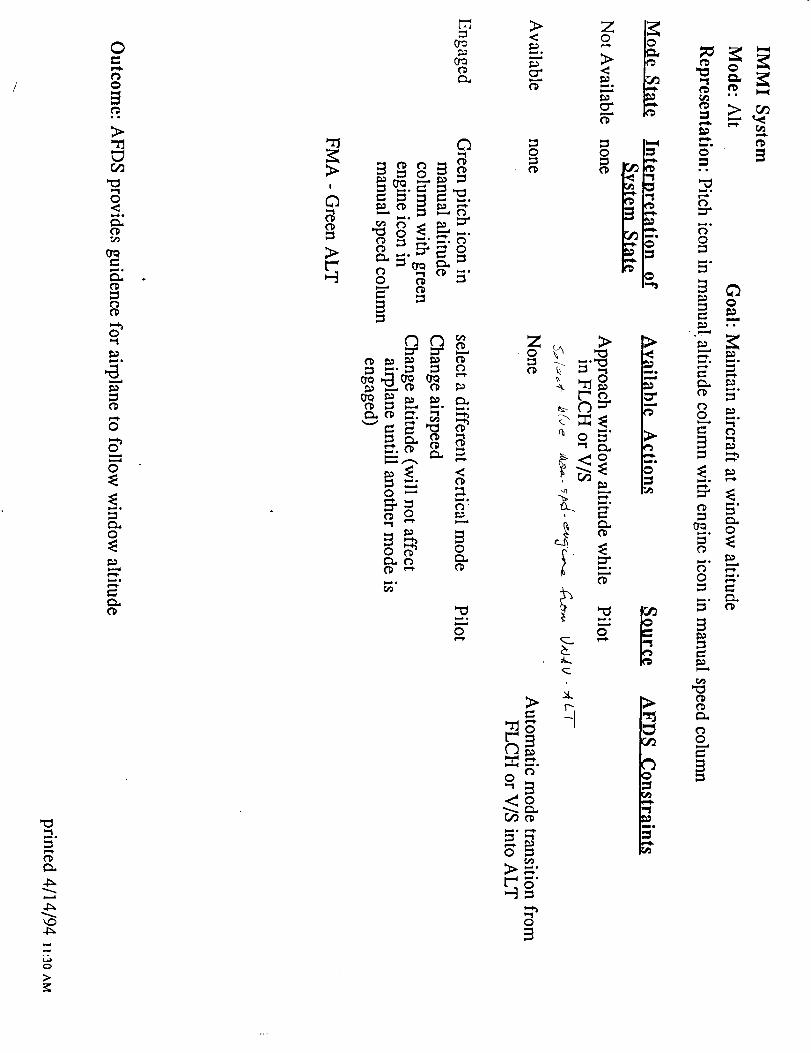
=].
L_C=,
>
0
0
eJ
>.
0
=O,J*
0
0
j,,,,i,
0
I,_lo
o_ o_ _
.,:'._ _ _
0 '-__ -"(_"
o_ o
0
Z >
__
b
0
0
_.0
=a0 _
0
_ 0
_. 0
0

(-_
J_
0
o
oo
>
o
b--_o
o
o o

Appendix 4

May 22,1995Rev
IMMI - SFO to LAX
ATC Script
This is a flight starting at the holding short position of runway01R at the SanFrancisco International Airport. The crew will enter the flightdeck with engines
running. All checklists through the Before Take-off Checklist will have beencompleted. The only preflight tasks to beperformed by the crew will be set up ofthe MCP and loading the FMC. Afterobtaining ATC clearance, they will takeoff
and proceed to the Los Angeleslnternational Airpo, it via a normal routing. There
will be no malfunctions along the way. ,.
IP 1 SFO RWY 01R
N 37.605W 122.381666
HDG 130
Altitude 11ft.
InitialConditions:
GW- 190,000 Ibs.(ACFS) 620,000 Ibs (747)
Fuel- 30,000 Ibs. (ACFS) 100,000 Ibs (747)_ Altimeter- 29.92
•Wind - 0/0
Weather:SFO - Clear, 50 nm vis
Enroute - Clear, 50 nm vis., TURB - Level 4, FL280 thru FL360Level 1 at FL370
s
LAX - r'l,-,,_r _r_ .... ;° CIG1500 OCST 5 FZ TOPS REPTD 3500_,./j,_.e,,_*j I _,./,,./ _llll VI_,',
Airborn IP ,_;
This is a flight starting at approximately 50 nm prior to top of descent fortheSADDE 5 arrival for Los Angeles International Airport. The onlypreflight tasks to
be performed by the crew will b.e set up of the MCP andloading the FMC. After
obtaining ATC clearance, they Will proceed to the-Los Angeles International
Airport viaa normal routing. There will be no malfunctions along the way.
IP2 APPROX 50 nm prior T/D
N 35.750W 120.016666
HDG 130Altitude FL330
Speed/Mach 0.82
InitialConditions:
GW- 190,000 Ibs.Fuel- 30,000 Ibs.
Altimeter- 29.92Wind - CALM
t Page 1SFO-LAX_REV


• ° r .'.
ATC PHRAESOLOGY
(After crew calls for clearance)
SFO CLR: NASA_ 8001 IS CLEAREE) TO THE LAX AIRPORT VIATHE PORTE 9 DEPARTURE, AVE TRANSITION,
FLIGHTPLAN ROUTE. MAINTAIN F-L-2-2_"60(3.0, EXPECT
FL330 10 MINUTES AFTERDEPARTUR'E.DEPARTURE FREQUENCY WILL BE 135.1, SQUAWK
3724.DO NOT EXCEED 250 KNOTS UNTIL ADVISED.
(After the crew calls for takeoff)
SFO TWR: NASA8001, AMEND YOUR CLEARANCE, CROSS PORTE
ABOVE 9000 AND BELOW 11000 FEET. TAXI INTO
POSITION AND HOLD, RWY 1R.
(Give the crew time to enter the alt and take position)
SFO TWR: NASA8001, WIND Calm, CLEARED FOR TAKEOFF
(When the cab leaves 500)
SFO TWR: NASA8001, CONTACT BAY DEPARTURE
BAY DEP:
(After crew calls)
NASA8001 BAY DEPARTURE, RADAR CONTACT.
MAINTAIN 6,000
BAY DEP:
(When cab's heading is 200)
NASA8001, TURN R!GHT TO 230SPACING
LEFT TO 180 FOR
(After 30 seconds)
BAY DEP: NASA8001, TURN _ RIGHTTO xxx, INTERCEPT AND
RESUrE1E THE PORTE 9 DEPARTURE
% D'
(As cab approaches 6_)00 3,500_ _
BAY DEP: NASA8001, CROSS °ODTC A_O° 9el 0 w __ nnn| i i | _ • • | | i _ • • i = ,vvv,
CLIMB UNRESTRICTED AND MAINTAIN 15,000
(As cab approaches 10,000)
BAY DEP: NASA8001, CONTACT OAK CENTER ON 125.45
(After crew calls)
SFO-LAX_REV Page 2


OAK 12L: NASA8001 OAK CENTER, ROG'ER
(As cab approaches 15,000)
OAK 12L:
OAK 12L:
NASA8001, CLIMB AND MAINTAIN FtL2.40, RESUME
NORMAL SPEED
i
(As cab approaches 20,000.) .
NASA8001, CONTACT OAK CENTER ON 133.7
(After crew calls) ,.
OAK 15H: NASA8001 _ ROGER
OAK !5H: HASA£O0!, CLIMB AND MAINTAI'N FL290, EXPEDITE
THROUGH ,EL-2-4G FL250
(At 25,000)
OAK 15H: NASA8001, CLIMB AND MAINTAIN FL370 -TURBULENCE
OAK 15H'
LAX 26H:
(At OAK/LAX border)
NASA8001, CONTACT LAX CENTER ON 124.15
(After crew cails) • !.:,o,i
!:
NASAS001 LAX CENTER F"L370 ROGER
(At .84) ,
Note for the researchers: the ACFS is unable to attain asPeed in excess of Math..8_..55
LAX 26H:
LAX 26H:
YOURDESCENT AT THE $1M 58 DME, AT 280
KNOTS, LAX ALTIMETER29.92
SFO.LAX_REV
NASA8001, CLEARED FOR THE SADDE 5 ARRIVAL.
DESCEND AT PILOT'S DISCRETION, CROSS SIMON AT AND
MAINTAIN 12,000. BEG!N YOURDESCENT AT THE F!M 64 DME,
AT 280 KNOTS, LAX ALTIMETER29.92
-OR-
(Between .82 and'.84) .I" i
NASA8001, CLEARED FOR THE SADDE 5 ARRIVAL.
CROSS SIMON AT AND MAINTAIN f2,000. BEGIN
Page 3


LAX 26H:
• ° :'.°
%},
-OR-
(Below .82)
NASA8001, CLEARED FOR THE SADDE 5 ARRIVAL.CROSS SIMON AT AND MAINTAIN 12,1300. BEGIN
YOURDESCENT AT THE FIM 50 DME, AT 280
KNOTS, LAX ALTIMETER30.01 •
LAX26H:
(When cab approaches 24,000)
o
NASA8001, CONTACT LAX CENTER ON 132.6
LAX 14 L:
(After crew calls)
o.
NASA8001 FLxxx, ROGER
(When cab passes 13,000)
LAX 14L: NASA8001 CONTACT SOCAL APPROACH ON 124.5
(After crew calls)
SOCAL APP: NASA8001 SOCAL APPROACH ROG_. R, CROSS SADDE
AT 250 KNOTS AND BAYST AT 10,000
(When cab passes SADDE)
Note for the researcher: If the crew loads andexecutes the ILS 24R, they will be
unable tO changeto an ILS 25L :._
SOCAL APP: NASA8001, DEPART SMO HEADING 070 EORVECTORS TO THE FINAL APPROACH
COURSE. 8ETM_74_-_ EXPECT ILS 24L- R
APPROACH. IF 25L BEOOMES AVAILABLE,'I WILL OHANGE YOUR
RUNWAY.
(When cab passes BAYST).s
SOCAL APP: NASA8001, REDUCE SPEED TO 200"
(When cab passes SMO)
SOCAL APP: NASA8001, DESCEND AND MAINTAIN 5,000
(When cab passes 6,000)
SOCAL APP: NASA8001 REDUCE SPEED TO 180
SFO-LAX_REV°_
Page 4
-


(When cab ,.,_,_,.v..,v,._.._,-,,',-,',_,'_,,-o.=^_,'P-v_,._.is 1 mi edst.of SAPPI)
SOCAL APP:NASA8001, TURN RIGHT HEADING 160, FOR VECTORS
TO THE FINAL APPROACH ILS _24R. DESCEND
AND MAINTAIN 4,000
(As cab passes 4_,500) '"
SOCAL APP: NASA8001 REDUCE SPEED TO. 170
(When cab approaches final)
SOCAL APP: NASA8001, xx MILES FROM MMMA- ROMEN, TURN RIGHTHEADING 220, MAINTAIN _ 4000 UNTIL ESTABLISHED ON THE
LOCALIZER, CLEARED FOR ILS25L ILS24R APPROACH
(When LOC and G/S have engaged)
SOCAL APP: NASASO01, xxx MILES FROM L/MMA, TURN LEFT HEAD/NG 220VECTOR FOR THE/LS25L LOCAL/ZER, MA/NTA/N 3000 UNTIL
ESTABLISHED, CLEARED FOR THE ILS25L APPROACH.
(When cab is on final)
SOCAL APP: NASA8001, MAINTAIN 170 KNOTS TO LIMMA,
CONTACT LAX TOWER ON 120.95
LAX TWR: NASA8001LAND 25L
LAX TWR:
After crew calls)
LAX TOWER, WIND CALM, CLEARED TO
(When cab approaches taxi speed)
NASA8001 JUST STOP ON THE RUNWAY
SFO-LAX REV
"F.
_°°
Page 5


Appendix 5


SCENARIO
S FO -LAX
SFO..PORTE9.AVE.FIM.FIM6..LAX
FL 330 (note this FL is lower than the final ATCclearance. We are looking for a problem here. )
Departure Clearance
CLDR:
"NASA eight hundred is cleared to the Los Angeles International
Airport as filed, on departure fly heading 281 to the Porte 9
departure cross Porte above niner thousand and at or below one one
thousand, climb and maintain six thousand, expect higher one zero
minutes after departure, do not exceed two hundred fifty knots until
advised, departure frequency will be one twenty one point three,
squawk 3654."
or , if Departure Clearance by ACARS:
**DPTR CLRNC**
FLT 800 SFO - LAX
NASA800 KSFO
/B757/ P1815 RQ330
ZPDR 3654
MAINT 6000 CROSS PORTE
ABOVE 9000 AND BELOW
Ii000 EXP REQ ALT I0 MIN
AFT T/O
GND CTL FREQ 121.8
/DPTR CTL SEE SID
DO NOT EXCEED 250 KTS
UNTIL ADVISED
EXPECT RWY 28L DEPT
KSFO.PORTE9.AVE.FIM.
FIM6..LAX
/747-4/ for the -400
A/C Call for push back clearance
Ground:
"NASA eight hundred, clear to push"
A/C Call for taxi clearance
Ground:
"NASA eight hundred, taxi to runway 28L via the inner and Foxtrot."
[Note: 747-400s are restricted from using taxiway E to or
from taxiway B]
Normal takeoff clearance.
After Takeoff and prior to i000':
"NASA 800 contact departure"
_D


NASA 800 checks in with departure ". ..... "
"NASA 800 Bay departure radar contact"
Radio chatter from other pilots in area ......
We expect the crews to be flying in LNAV and VNAV with A/P engaged
before reaching the first turn point.The SID calls for a i01 dezr_e left turn.
Upon rolling out on the 180 degree heading
"NASA eight hundred, turn left i0 degrees for traffic."
30 seconds later
"NASA eight hundred, resume the Porte 9 departure."
What we expect to see:
MCP: Possible engagement of heading select with the heading bug behind
the airplane.
IMMI: pilot has to find the heading bug in order to engage the mode.
Can't make this mistake on our interface.
Rationale: It's been observed in training and from the jumpseat. It
will be i_©ortant to keep the crew busy looking for traffic while the
airplane is making the turn in LNAV.
...... (set up an unexpected VNAV level-off)
Out of 5000'
"NASA 800 climb unrestricted to one five thousands"
What we expect to see:
MCP: We have now set up the analog of the Peblel departure from SAN.
They will put 15000 in the window, but an at-or-below altitude
restriction remains at PESCA. May see an unexpected level off. It will
be essential to have the performance characteristics worked out so
that the airplane will reach i0000 prior to Porte. Since Porte
normally required at-or-above 9000, this should be assured in a light
747-400.
IMMI: The vertical path display should make the level-off apparent.
...... (hand off to Center)
Out of ii000'
"NASA 800 contact Oakland Center on 125.45"
(clearance higher)
Let them level at FLI50 ,(_
When level at FLI50
"NASA 800 climb and maintain FL290" ' _
........ (set up wingtip LNAV)
after crossing Porte
"NASA 800 turn left 20 degrees for traffic" (to 115)
This has the effect of cutting the Pesca waypoint corner of the route
........................ (wingtip LNAV)
When almost abeam of Pesca
"NASA 800, traffic no factor, resume the Porte 9 departure, thanks for


your help."
What we expect to see:
MCP: Possible engagement of LNAVwith active waypoint abeam. Thisproduces a steep right turn toward Pesca when pilots expect a shallow
left turn to line up with Wages waypoint in front of them.
IMMI: Pilots have to find the active waypoint to engage the mode. It
should be obvious that it's off the end of the wing. _o, they go to
CDU and make the next wpt active, then engage it.
Rationale: MCP LNAV is a "meta-button." It has no content. IMMI's
engagement operation requires the pilot to interacU with the spatial
meaning of the operation.
(hand off to Center 2)
Out of FL210"NASA 800 contact Oakland Center on XXXXXX" (<- need freq)
A/C "Oakland Center NASA 800, out of 220 for 290."
......... -- (Center 2 pick up and expedite climb)
"NASA 800 roger, expedite your climb through FL240."
Features: Speed intervention is not shown as available on either
interface. The (someday) blue speed select button on the IMMI gives a
clue that something is available there. Two problems here. I) Getting
a mode or sub-mode that will control speed. 2) What is the 'best rate
of climb' speed right now?
What we expect to see:
MCP: "how do I find that? 250 ought to be about right." The
right way to do it is to go to the VNAV page in the CDU. Field 6R of
the VNAV page shows Vx. And from school you remeK_er<that you can
get a good approximation of Vy by adding 25 Knots to Vx.
IMMI: If they can get into speed intervention, setting the icon next
to the Vy bug should be easy. ' ,
(resume normal speed, final alt clearance)
out of FL250
"NASA 800
resume normal speed, (if pilots forgot to resume on own)
(or)
climb and maintain FL370
thanks for your help."
(possible unexpected level off at cruise)
Final clearance is higher than initial clearance entered into CDU as
cruise altitude. This is a hidden state in the MCP system.
What we expect to see:J
HCP:
Expect that the pilots may not edit the cruise page in the CDU to
reflect the final ATC clearance_and will be surprised when the
airplane levels prior to the altitude in the MCP. window,+
IMMI:
Expect that the pilots will notice the magenta line levels prior to
the window altitude line and they will edit the CDU to'change cruise
altitude to reflect the final ATC clearance.


:(Descent Clearance_}
"NASA800 cleared for the Runway 24/25 Profile descent"
(Over Speed lose path)During descent a tail wind forces the airplane to use higher andhigher speeds to stay on the path. As the airspeed approaches the topof the operating envelope, the FMCabandons pitching to the path withVNAVPATHand instead pitches to a speed with VNAVSPD.
What we expect to see:
MCP:
(a) scratch pad message "drag required", (b) overspeed warning boxes
on PFD airspeed tape move toward the current airspeed marker, (c)
FMA's change from VNAV PTH to VNAV SPD. The pilots may not notice
these changes and the mode transition.
I]J/JI:
(a) VPD predicted path will diverge from the FMC path at the 4D point
of the expected mode transition, (b) the IMMI current airspeed window
will climb up on the speed tape toward the overspeed warning area, (c)
the pitch to path icon will turn amber, (d) the _itch and engine icons
will swap sides of the IMMI when VNAV PTH changes" to. VNAV SPD, (e) all
the changes above for the MCP will also occur. We expect the pilots
will notice these changes before the mode transition occurs.
More clearances need to be written here for standard descent.
Los Angeles Airport information Sierra, 1650 zulu ....
Somewhere in here
"Expect runway 24R."
East of Santa Monica:
"NASA 800 descend and maintain 5000'"
Over do_-town:
"NASA 800 turn right heading 160 descend and maintain 4000"
Expect to see: use of V/S to make a smoother decent _rom 5000 to 4000.
The IMMI will have the opportunity to show its awkward V/S interface
which may be harder to use than the -400.
Turn inbound
"NASA 800 turn right heading 220 vector to the runway 24R localizer,
cleared for the runway 24R approach." ¢_
mm
The vectors, altitudes, and approach clearance must be given in such a
way that LOC and G/S can engage well outside the outer marker. The
altitude of the glideslope at Merce is 4783 MSL. Joining the localizer
at 4000 will lead to G/S intercept about 6 miles outside of Romen.
Once the aircraft is locked in on 24R,
ATC calls for a runway change. (This works in the Boeing Datalink
study scenario, consult that for details).
"NASA 800, 24R glideslope signal is fluctuating, turn left to heading
220 vector for the Runway 25L localizer, cleared to land, runway 25L."
Expect to see:
BOTH:

Difficulties in disengaging from the LANDconfiguration
MCP:NO indication that TOGAis the only mode available.
IMMI:Information available perceptually that no modes '-..e_cept TOGA- areavailable (no blue on the screen). This should help cgews rememberthat they have to disengage everything to get anbther pitch or rollmode.
On 1 mile final, another aircraft moves onto the runway."NASA800 go around fly the published missed approach.
A/C acknowledge
"NASA 800 contact departure on 124.3"
A/C "Departure, NASA800, missed approach off 25L"
"NASA 800 climb and maintain 3000 proceed to the INISH intersection aspublished hold west on the SEALBEACH251 degree radial, left hand turns."
Release from hold and normal landing on 25L
b-
