the influence of texture on the shape-...
TRANSCRIPT

THE INFLUENCE OF TEXTURE ON THE SHAPE-
MEMORY EFFECT IN POLYCRYSTALS
Y. C. SHU and K. BHATTACHARYA{Division of Engineering and Applied Science, 104-44, California Institute of Technology, Pasadena,
CA 91125, U.S.A.
(Received 29 October 1997; accepted 18 May 1998)
AbstractÐA model is developed to show that texture is a crucial factor in determining the shape-memorye�ect in polycrystals. In particular, it is established that texture is the reason why the strains recoverable inTi±Ni are so much larger than those in Cu-based shape-memory alloys in rolled, extruded and drawn spe-cimens. Further, it is shown that both these materials recover relatively small strains in sputter-depositedthin ®lms due to unfavorable texture. It is found that even the qualitative behavior of combined tension±torsion can critically depend on the texture. The results are in good agreement with experimental obser-vations. Finally, textures are suggested for improved shape-memory e�ect. # 1998 Acta Metallurgica Inc.Published by Elsevier Science Ltd. All rights reserved.
1. INTRODUCTION
Shape-memory e�ect (SME) is a phenomenonwhere deformation su�ered below a critical tem-
perature can be recovered on heating. About 20±30alloys are known to exhibit SME in single crystals.
However, the degree to which they retain theirshape-memory behavior in polycrystals is widely
varied. Some materials have good shape-memorybehavior as single crystals but little or none as poly-crystals, while others display good SME even as
polycrystals. Bhattacharya and Kohn [1] haveargued that crystallographic symmetry is a very im-
portant factor in determining the recoverable strainsin polycrystals: alloys which undergo small change
in symmetry (cubic to tetragonal or trigonal) havevirtually no recoverable strains in polycrystals,
while alloys which undergo large change in sym-metry (cubic to orthorhombic or monoclinic)always recover at least some strain even in polycrys-
tals. While this explains much experimental obser-vation, it fails to make any distinction within the
latter group of alloys. In particular, it is unable toexplain why Ti±Ni is so much better than Cu-based
SMAs (Table 1) since both undergo cubic±monocli-nic transformation and have similar transformation
strains. They speculated on, but did not systemati-cally explore, the role of texture.
Typically, shape-memory materials are preparedby casting followed by hot-working (rolling for
strips or drawing for wires) followed by heat treat-ment. Therefore, it is natural to expect that the
polycrystals are textured and this has been exper-
imentally con®rmed in Ti±Ni rolled sheets [8, 16±
21]; Ti±Ni rods and Ti±Ni±Cu wires [22, 23]; Cu±
Zn±Al rolled sheets [24±26]; and Cu±Zn±Al drawn
wires [27]. Other processing means like rapid
solidi®cation [8, 28±30] and sputtering [31] also
endow the polycrystal with texture.
In this paper, we explore the e�ect of texture on
SME by extending the framework of Bhattacharya
and Kohn [32]. We use ``recoverable strain'' as a
measure of SME and develop a model to estimate it
for a polycrystal with given texture. A geometric
point of view is adopted for brevity. We note that it
is possible to justify this geometric picture using
energy minimization, and we refer interested readers
to Refs [32, 33] for details. We also note that the
strains recoverable by superelasticity or pseudoelas-
ticity are essentially identical to those recoverable
by SME; so our model also provides a means to
evaluate the e�ect of texture on superelasticity.
Using this model, we show that texture is a very im-
portant reason for the di�erence between Ti±Ni
and Cu-based SMAs: the texture that develops
during rolling or drawing is very desirable from the
point of view of SME in Ti±Ni while these textures
are undesirable in Cu-based alloys. We also ®nd
that sputtering textures in both Ti±Ni and Cu-
based shape-memory thin ®lms are not favorable
for large recoverable strain. This is consistent with
experimental observations. Finally, we explore in
some detail the predicted recoverable strains for
various textures in an attempt to recommend tex-
tures for large SME.
Acta mater. Vol. 46, No. 15, pp. 5457±5473, 1998# 1998 Acta Metallurgica Inc.
Published by Elsevier Science Ltd. All rights reservedPrinted in Great Britain
1359-6454/98 $19.00+0.00PII: S1359-6454(98)00184-0
{To whom all correspondence should be addressed.
5457

The source of the SME is a martensitic phase
transformation. This gives rise to microstructure of
martensitic variants below the transformation tem-
perature, and certain deformations are recoverable
because they are accomplished not by slip or the
motion of dislocations but by rearrangement of the
microstructure. In a single crystal, it is relatively
easy to calculate the recoverable strains and we
characterize these using SÐthe set of recoverable
strains in a single crystalÐin Section 2.1. In a poly-
crystal, each grain is constrained by its neighbors as
it tries to deform by rearranging its microstructure.
Therefore, the set PÐthe set of recoverable strains
in a polycrystalÐdescribed in Section 2.2 is rather
di�cult to calculate. Further, its calculation
requires knowledge of the shape and orientation of
each grain which is di�cult to obtain. Finally, even
if we measure the exact texture and solve the pro-
blem for a speci®c specimen, the resulting set is
valid only for that specimen; we have to repeat the
process for each specimen. Therefore, we need an
easily computable, but reasonable estimate of this
set which can use readily measurable and character-
izable information about the texture. This is accom-
plished using boundsÐthe inner or the Taylor
bound Pi and the outer or the Sachs bound PoÐin
Section 2.3. The inner bound is obtained by impos-
ing the same strain on each grain while the outer
bound is obtained by ignoring compatibility
between grains.
We specialize on speci®c loads in Section 3.
Uniaxial tension or compression is considered as an
example of homogeneous loads and combined ten-
sion±torsion as an example of inhomogeneous
loads. We show that under uniaxial loading of
single crystals, our model essentially coincides with
that of Saburi and Nenno [34]. In polycrystals, we
again provide an inner bound and an outer bound
of the recoverable strain. For monoclinic marten-
sites, we also provide an inner estimate.
We believe that the inner bound is in fact a
reasonable estimate of the actual recoverable
strains. An example is provided to justify this in
Section 3.2. Bhattacharya and Kohn [32] as well as
Kohn and Niethammer [35] have derived rigorous
results in dimensionally reduced problems to sup-
port this argument. Therefore, we use the inner
bound, which can be rewritten as a linear program-
ming problem, as our fundamental tool for evaluat-
ing the e�ect of texture.
The outer bound, on the other hand, is often a
large overestimate. In uniaxial tension, the outer
bound is the average of the strain of the most
favorable martensitic variant in each grain. Various
authors [17, 19] have used this as a model for the
recoverable strain and have predicted almost twice
the observed recoverable strain.
We extend these ideas to the behavior of very
thin ®lms in Section 4. Shape-memory materials
have the largest energy output per unit volume per
cycle of known actuator systems [36]. This fact,
together with the enhanced rate of heat transfer in
thin ®lms, makes these alloys ideal for microactua-
tor, micropump and for microelectromechanical
systems (MEMS) applications and this has motiv-
ated many experimental e�orts (see, e.g. Refs [37±
40]). All of these e�orts have concentrated on Ti±
Ni-based alloys and use sputtering to produce
polycrystalline ®lms. However, it is not clear that
Ti±Ni is the ideal material in thin ®lms. It is well
known that microstructure can be signi®cantly
di�erent in thin ®lms as compared to bulk ma-
terials. Recently Bhattacharya and James [41] have
developed a theory of martensitic thin ®lms which
captures this e�ect. We discuss the extension of
this theory to polycrystalline thin ®lms in this
section.
We use our models to explore the e�ect of tex-
ture on recoverable strains in uniaxial tension in
Section 5 and in combined tension±torsion in
Section 6. Recently Zhao and Beyer [20, 21] as
well as other groups [17±19] have measured both
the recoverable strain and the texture of rolled
Ti±Ni and closely related materials. We calculate
the recoverable strains for their observed texture
and compare them with experimental observations
in Section 5.1. Both Ti±Ni and Cu-based alloys,
and, in fact, most SMAs, have a body-centered-
cubic (b.c.c.) superlattice structure in their parent
phases. We calculate recoverable strains for typi-
cal b.c.c. rolling and drawing textures, and also
for textures formed by rapid solidi®cation and
sputtering. Figures 9 and 10 highlight the striking
contrast in SME between Ti±Ni and Cu-based
alloys in rolling textures. The results for various
other textures are shown in Table 5. In Section 6,
we ®nd that even the qualitative behavior of com-
bined tension±torsion can depend on the texture
as shown in Fig. 11. We conclude in Section 7
with a discussion.
Table 1. Experimental observations of the recoverable strains in some Cu-based SMAs and Ti±Ni
SMA Recoverable strain
Single crystals Polycrystals
Cu±Zn±Al 2±9% depending on orientation [2, 3] around 2% in general [4±7], but can be up to 6% in textured ribbons [8, 9]Cu±Al±Ni
Ti±Ni 3±10% depending on orientation [10, 11] 5±8% in drawn wires and rolled sheets [12±15]
SHU and BHATTACHARYA: THE INFLUENCE OF TEXTURE ON SHAPE-MEMORY5458

2. RECOVERABLE STRAIN
2.1. Recoverable strain in a single crystal
Consider a single crystal of austenite and choosethis as the reference con®guration, so the austenitehas stress-free strain e�0� � 0. As it is cooled, it
transforms to martensite. In SMAs, the austenitelattice has cubic symmetry while the martensite lat-tice has smaller symmetry such as tetragonal, trigo-nal, orthorhombic or monoclinic symmetry. This
gives rise to k symmetry-related variants of marten-site. The transformation from the austenite to theith variant of martensite is described by the trans-
formation strain e(i). It can be determined from thechange of symmetry and lattice parameters asshown in Table 2. Schematically, we mark each
transformation strain as a point . in Fig. 1.
When a single crystal is below the transformation
temperature, it can form microstructures by coher-
ently mixing the variants of martensite. It deforms
if it can by rearranging the microstructure. When it
is subsequently heated, each variant reverts to the
austenite and all the strain is recovered. Thus, the
strains that a single crystal can recover are exactly
those that are associated with a microstructure of
martensitic variants. Thus, S, the set of recoverable
strains in a single crystal, is exactly the set of strains
one can make by coherent microstructures of mar-
tensite.
Consider two variants of martensiteÐsay 1 and
2Ðand suppose that these variants are compatible
or twin-related. In other words, assume that the
transformation strains e(1) and e(2) satisfy the com-
patibility condition
Fig. 1. (a) Recoverable strains in a single crystal when all pairs of martensitic variants are compatible.(b) The set of recoverable strains Smono in a single crystal undergoing cubic±monoclinic transform-ation. This nonconvex set Smono is bounded by orthorhombic Sorth and monoclinic Sc
mono estimates.
Table 2. Transformation strains associated with di�erent changes of symmetry. Only e(1) is shown here; the rest e(2), . . . , e(k) can beobtained from e(1) by symmetry by permuting the basis. In Monoclinic-I, the axis of monoclinic symmetry corresponds to h110icubic whilein Monoclinic-II, the axis of monoclinic symmetry corresponds to h100icubic. We choose variant 1 so that d>0 (orthorhombic and mono-
clinic cases) and e>0 (monoclinic case). The compositions of all alloys are given in atomic percentages unless otherwise speci®ed
Symmetry of martensite k Transformationstrain e(1)
Examples Lattice parameters
Tetragonal 3
� a 0 00 a 00 0 b
�Ni±36.8Al [42, 43] a=ÿ 0.0608, b = 0.1302
Trigonal 4
� b a aa b aa a b
�Ti±50.5Ni (R-phase) [44] a= 0.0047, b = 0
g01 Cu±14Al±4Ni (wt%) [45] a = 0.0425, b =ÿ 0.0822, d = 0.0194
Orthorhombic 6
� a d 0d a 00 0 b
�Ti±45Ni±5Cu [46] a = 0.0240, b =ÿ 0.0420, d = 0.0310
Ti±49.8Ni [47, 48] a= 0.0243, b =ÿ 0.0437, d= 0.0580, e= 0.0427Monoclinic-I 12
� a d ed a ee e b
�Ti±45Ni±5Cu [46] a= 0.0232, b =ÿ 0.0410, d= 0.0532, e= 0.0395
Cu±15Zn±17Al [49] a= 0.0483, b =ÿ 0.0907, d= 0.0249, e= 0.0383Monoclinic-II 12
� a� e d 0d aÿ e 00 0 b
�b01 Cu±14Al±4Ni (wt%) [50] a= 0.0442, b =ÿ 0.0822, d = 0.0160, e= 0.06
SHU and BHATTACHARYA: THE INFLUENCE OF TEXTURE ON SHAPE-MEMORY 5459

e�1� ÿ e�2� � 1
2�a n� n a� �1�
for some vectors a and n. Here a n denotes the
matrix with components �a n�ij � ainj. Then, we
can form ®ne twins whose overall strain is the aver-
age of the transformation strains of these two var-
iants. Geometrically, this average strain is a point
on the line connecting these two variants, and by
choosing the appropriate volume fraction we con-
clude that all strains on the line joining e(1) and e(2)
are recoverable. Furthermore, if all the variants are
pair-wise compatible, S is the convex hull of the
transformation strains [51]; i.e.
S ��e : e �
Xki�1
mie�i �, mir0,
Xki�1
mi � 1
�: �2�
This is shown schematically as the shaded set in
Fig. 1(a). The variants are pair-wise compatible in
cubic±tetragonal, cubic±trigonal and cubic±orthor-
hombic transformation and we can obtain S in
these cases.
The transformation strains of monoclinic marten-
sites are not pair-wise compatible and the set of
recoverable strains Smono is not the convex hull of
the transformation strains. This is because there are
some strains that cannot be achieved by coherent
microstructures of the di�erent martensitic variants.
Unfortunately, we do not know the precise set
Smono, so we bound it using ``orthorhombic'' and
``monoclinic'' estimates as shown in Fig. 1(b). Let
Scmono be the convex hull of the monoclinic variants
and let Sorth be the convex hull of a ®ctitious
cubic±orthorhombic transformation obtained by
setting e = 0 in e(1), . . . , e(12). We can show thatSorth �Smono �Sc
mono [1, 32].
Finally, shape-memory alloys are self-accommo-dating: they can undergo the austenite±martensitetransformation with no apparent shape change. In
other words, there is a microstructure of martensiticvariants whose average strain is e(0) or e�0� 2S [52]as also shown in Fig. 1.
Putting all this together, the situation is as fol-lows. At high temperatures, the single crystal is inthe austenite state with overall strain e(0). On cool-
ing it transforms to self-accommodated martensite,also with strain e(0). We can now deform it freely aslong as the strain is in the set S. On subsequentheating, no matter where it is in the set S it reverts
once again to austenite with overall strain e(0) reco-vering all imposed strain. If we deform beyond theset S at low temperature, elastic stresses build up
resisting the deformation, resulting in dislocationmotion or fracture and non-recoverability.
2.2. Recoverable strain in a polycrystal
We now turn to a polycrystal. A polycrystal is anaggregate of a great number of single crystal grains
with di�erent orientations. We describe the textureof a polycrystal by a rotation-valued function R(x).R(x) gives the orientation of the crystal at the point
x relative to some ®xed reference crystal.Suppose we start in the austenite and cool. Each
grain transforms to a self-accommodated state.
Suppose we now impose an overall strain eo, andask if it is recoverable. Once again, it is if it can beaccommodated by a microstructure of martensite ineach grain. However, each grain has its own set of
Fig. 2. (a) Recoverable strains in a polycrystal (made of two grains of equal volume fraction). Eachgrain has its own set of recoverable strains (the two triangles) obtained by a rotation of the basic setS. The polycrystal can recover all strains inside the inner bound Pi, but none outside the outer boundPo. (b) Inner and outer bounds of recoverable strain can be wide apart when S has small dimension
(schematically a line).
SHU and BHATTACHARYA: THE INFLUENCE OF TEXTURE ON SHAPE-MEMORY5460

recoverable strains
S�x� � R�x�SRT�x� �3�which is obtained by the rotation of the basic set Sthrough R(x) as shown in Fig. 2(a). Thus, in orderto accommodate eo, the polycrystal has to ®nd (apossibly inhomogeneous but compatible) strain ®eld
e(x) that satis®es di�erent constraints in di�erentgrains (e�x� 2S�x�) and whose average is eo. Thus,P, the set of recoverable strains in a polycrystal, is
given by
P ��eo : eo �
�Oÿ e�x� dx, e�x� 2 S�x�,
and e�x� a compatible strain field
�: �4�
Above�O � � � � �1=Vol:O�
�O denotes the average
over O. We will estimate this set in Section 2.3. Fornow, we simply note that P is not empty in a
SMA, since it always contains e(0) due to self-ac-commodation.Once again the situation is as described at the
end of Section 2.1 with the set P replacing S.
2.3. Bounds on recoverable strain in a polycrystal
We now estimate the set P using bounds. The
®rst, and what we will ®nd to be the most useful,bound is the inner bound or Taylor bound.Consider an average strain e. Suppose e is recover-able in each grain, i.e. e 2S�x� for ``every'' x 2 O.Then, clearly e is recoverable in the polycrystal ore 2 P. Thus
P � Pi � fe:RT�x�eR�x� 2S for ``every'' x
2 Og: �5�
The set Pi is shown in the shaded region of
Fig. 2(a). Geometrically it is the intersection of theset of recoverable strains of the di�erent grains.The set Pi contains all strains that can be recovered
without the cooperative e�ect of the di�erentgrains. Hence, it is a pessimistic or inner bound.The other bound is the outer bound or Sachs
bound. This bound is obtained by allowing each
grain to deform as it wishes and forgetting aboutthe constraints they impose on each other. Thus
P � Po ��e : e �
�Oÿ e�x� dx, e�x� 2S�x�,
and e�x� not necessarily compatible
�: �6�
The geometric meaning of this set is harder to visu-
alize. Scale the sets S(x) for each grain by its ownvolume fraction. Po is the set of all points that canbe obtained by adding (vectorically) points in all ofthese scaled sets as shown in Fig. 2(a). The set Po
does not account for the constraints between grains;hence, it is an optimistic or outer bound.
It may so happen that the inner and outerbounds are wide apart if S has small dimension.This is dramatically illustrated in Fig. 2(b) where
the set S is shown schematically as a line. In sucha situation, the inner bound reduces to a singlepoint, and we say that the inner bound Pi is trivial.
Bhattacharya and Kohn [32] have argued that theactual set P is also trivial in such a situation, i.e.P � Pi (also see Ref. [53]). In contrast, if S has
high dimension and spans deviatoric strains, the setPi is not trivial. In this case, it is generally not truethat P � Pi. However, we believe that even in thiscase, Pi is often a good estimate of P, i.e. P � Pi.
We will present examples in support of this claim inSection 3.2. Also see the recent work of Kohn andNiethammer [35].
We close this section by recalling the argumentsof Bhattacharya and Kohn [1] on the e�ect of sym-metry. If the change of symmetry is small, such as
cubic±tetragonal or cubic±trigonal transformation,the set S has low dimension; hence Pi is trivial andthe polycrystal has no recoverable strains except for
exceptional textures [Fig. 2(b)]. If, on the otherhand, the change of symmetry is large, such ascubic±orthorhombic and cubic±monoclinic trans-formation, the set S has full dimension. Therefore,
the polycrystal has some recoverable strains irre-spective of texture [Fig. 2(a)].
3. MAXIMUM RECOVERABLE STRAIN IN TENSIONAND TORSION
3.1. Extension or compression
Consider a polycrystalline SMA below the trans-
formation temperature in the self-accommodatedstate. Apply a uniaxial stress s to this specimen inthe x direction. We can show [33] that the maximum
recoverable strain eR is given by
eR � maxe2P�x � ex� if s > 0 �extension�mine2P�x � ex� if s<0 �compression�
�: �7�
The maximum recoverable strain in a single crystalis also given by equation (7) if P is replaced withS. Equation (7) has an interesting geometrical in-
terpretation. The maximum recoverable strain eR isthe maximum projection of the set P (or S) on theloading direction x x. In single crystals, it is clear
from Fig. 1 that the maximum projection of the setS is always equal to the maximum projection ofthe transformation strains e(1), . . . , e(k). Therefore, it
follows that variants coalescence under loading toproduce the most favorable variant in a single crys-tal. Thus, our model coincides with that of Saburi
and Nenno [34] except they use a geometricallynonlinear theory.In polycrystals, we cannot calculate eR since we
do not know P. However, we can bound it as
SHU and BHATTACHARYA: THE INFLUENCE OF TEXTURE ON SHAPE-MEMORY 5461
before using an inner bound eiR and outer bound eoR.For tensile loading
eiR � maxe2Pi�x � ex� and eoR � maxe2Po
�x � ex�: �8�It follows from equations (5)±(7) that eiRReRReoR.The inner bound eiR assumes that every grain under-
goes the same strain and it does not take into
account the cooperative response between grains.
On the other hand, the outer bound eoR assumes
that each grain picks its most favorable variant and
ignores the fact that the constraints from the neigh-
boring grains can suppress the most favorable var-
iant. We believe that the inner bound is a
reasonable estimate of the actual recoverable strain
(see Section 3.2).
Now consider a polycrystal made of N grains
with orientations R1, R2, . . . , RN and volume frac-
tion l1, l2, . . . , lN. We can now write eiR and eoR as
eiR � maxRTj eRj2S 8j�1,...,N�x � ex� �9�
eoR �XNj�1
maxe2S�ljvj � evj � �10�
where vj � RTj x. We can interpret equations (9) and
(10) geometrically as shown in Fig. 2(a): the inner
bound is the maximum projection of the set Pi on
the loading direction while the outer bound is the
average of the maximum projection of each set
RjSRTj on the loading direction weighted by its
volume fraction lj. Note also from Fig. 2(a) that eiRcan be strictly smaller than the smallest recoverable
strain amongst all grains.
We can rewrite equations (9) and (10) as linear
programming problems if S is the convex hull of
stress-free variants. The inner bound
eiR � maxm ji
�Xki�1
x � �m1i R1e�i �RT
1 �x�
�11�
where the maximum is taken over the following
constraints:Xki�1
m jiRje
�i �RTj �
Xki�1
m1i R1e�i �RT
1 for j � 2, . . . , N
Xki�1
m ji � 1, m j
ir 0 for j � 1, . . . , N �12�
and the outer bound
eoR�XNj�1
lj
max
mir0, Ski�1mi�1
x ��Xk
i�1miRje
�i �RTj
�x
!:
�13�
Recall that in the cubic±monoclinic transform-
ation Smono is unknown. Therefore, we cannot
evaluate equation (9). Instead, we use
eiR � maxRTj eRj2Sorth 8j�1,...,N�x � ex� �14�
eeR � maxRTj eRj2Sc
mono 8j�1,...,N�x � ex� �15�
eoR �XNj�1
maxe2Scmono�ljvj � evj � �16�
as the inner bound, inner estimate and outer
bound, respectively. We can rewrite equations (14)±(16) as linear programming problems as before.
3.2. Maximum recoverable strain in a laminatedpolycrystal
We have claimed above that the inner bound pro-
vides a reasonable estimate to the actual recover-able strain. This is justi®ed with an exampleÐapolycrystal with a laminated texture. Laminated
microstructures have been used extensively in thestudy of polycrystals and composite materials sincethe exact e�ective properties can be obtained by sol-
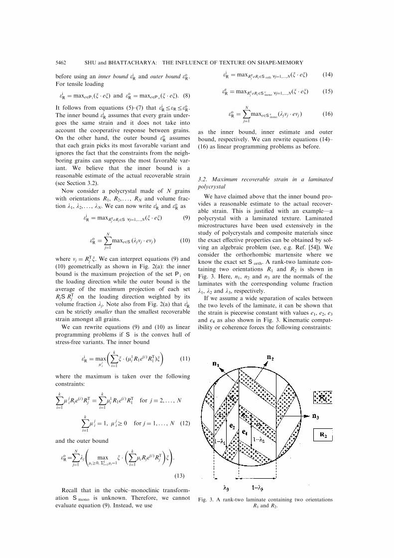
ving an algebraic problem (see, e.g. Ref. [54]). Weconsider the orthorhombic martensite where weknow the exact set Sorth. A rank-two laminate con-taining two orientations R1 and R2 is shown in
Fig. 3. Here, n1, n2 and n3 are the normals of thelaminates with the corresponding volume fractionl1, l2 and l3, respectively.If we assume a wide separation of scales between
the two levels of the laminate, it can be shown thatthe strain is piecewise constant with values e1, e2, e3and e4 as also shown in Fig. 3. Kinematic compat-ibility or coherence forces the following constraints:
Fig. 3. A rank-two laminate containing two orientationsR1 and R2.
SHU and BHATTACHARYA: THE INFLUENCE OF TEXTURE ON SHAPE-MEMORY5462

e1 ÿ e2 � 1
2�n1 m1 �m1 n1�,
e3 ÿ e4 � 1
2�n2 m2 �m2 n2�,
�l1e1 � �1ÿ l1�e2� ÿ �l2e3 � �1ÿ l2�e4�
� 1
2�n3 m3 �m3 n3� �17�
for some vectors m1, m2 and m3 and average strain
is
eave �l3�l1e1 � �1ÿ l1�e2�� �1ÿ l3��l2e3 � �1ÿ l2�e4�: �18�
Moreover, to be recoverable, e1, e2, e3 and e4 must
satisfy
RT1 e1R1, RT
2 e2R2, RT1 e3R1, RT
2 e4R2 2Sorth: �19�
Putting all these in equation (7), we can conclude
that for tensile loading in the x direction, the maxi-
mum recoverable strain is given by
eR � max x � eavex �20�where the maximum is taken over e1, e2, e3 and e4subject to constraints (17) and (18).
Let us consider two examples: Ti±40Ni±10Cu
(B19) and g01 Cu±14Al±4Ni (wt%), both undergoing
cubic±orthorhombic transformation. The texture,
normals and volume fraction of the rank-two lami-
nate are listed in Table 3 and the tensile loading
direction for both cases is x � �cos y,0,sin y�T for
various y. In fact, we will ®nd later that this is
exactly like the rolled sheet subjected to tensile
loading along the rolling plane (see Section 5 and
Fig. 6). Figure 4 shows the inner bound, the outer
bound and the exact value of the maximum reco-
verable strain calculated according to equations (9),
(10) and (20), respectively. We have repeated the
same calculations for di�erent laminates, i.e. for
di�erent normals of n1, n2 and n3. The results are
either the same or closer to the inner bound except
in a very few exceptional situations. We have also
performed the calculations for a rank-three lami-
nate. The results are even closer to the inner bound.
Table 3. Orientation, normals and volume fraction of the rank-two laminates used in the calculation for Ti±40Ni±10Cu (B19) and g01 Cu±
14Al±4Ni (wt%)
SMA Orientation Normals Volume fraction
R1 R2 n1 n2 n3 l1 l2 l3
Ti±40Ni±10Cu 1��2p� 1 ÿ1 01 1 00 0
���2p
�1��6p� ���
3p ÿ ���
3p
0���2p ���
2p ���
2p
ÿ1 ÿ1 2
�1��2p�ÿ1
01
�1��2p� 110
� � 100
�0.5 0.5 0.5
Cu±14Al±4Ni 1��2p� 1 ÿ1 0
0 0���2p
ÿ1 ÿ1 0
�1��6p� ���
3p ÿ ���
3p
01 1 2ÿ ���
2p ÿ ���
2p ���
2p
� � 001
�1��2p� 110
� � 100
�0.5 0.5 0.5
Fig. 4. The inner bound, outer bound and exact value of the maximum recoverable strain for the rank-two laminated polycrystal subjected to uniaxial tension in di�erent directions: (a) Ti±40Ni±10Cu (B19);
(b) g01 Cu±14Al±4Ni (wt%).
SHU and BHATTACHARYA: THE INFLUENCE OF TEXTURE ON SHAPE-MEMORY 5463
It is clear that the constraints between the grains isoverwhelming and hence eR � eiR. Finally, the draw-
back of the outer bound can also be seen especiallyin the case of g
01 Cu±14Al±4Ni (wt%) at the loading
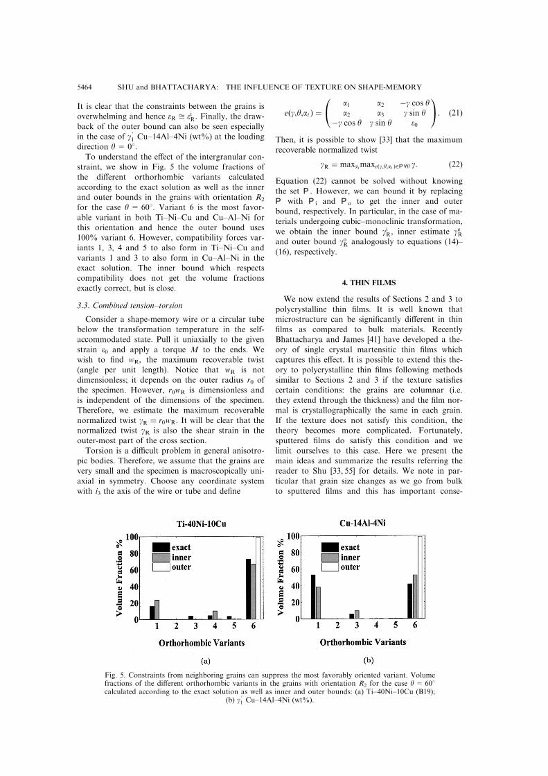
direction y= 08.To understand the e�ect of the intergranular con-
straint, we show in Fig. 5 the volume fractions ofthe di�erent orthorhombic variants calculated
according to the exact solution as well as the innerand outer bounds in the grains with orientation R2
for the case y = 608. Variant 6 is the most favor-
able variant in both Ti±Ni±Cu and Cu±Al±Ni forthis orientation and hence the outer bound uses100% variant 6. However, compatibility forces var-iants 1, 3, 4 and 5 to also form in Ti±Ni±Cu and
variants 1 and 3 to also form in Cu±Al±Ni in theexact solution. The inner bound which respectscompatibility does not get the volume fractions
exactly correct, but is close.
3.3. Combined tension±torsion
Consider a shape-memory wire or a circular tubebelow the transformation temperature in the self-accommodated state. Pull it uniaxially to the given
strain e0 and apply a torque M to the ends. Wewish to ®nd wR, the maximum recoverable twist(angle per unit length). Notice that wR is not
dimensionless; it depends on the outer radius r0 ofthe specimen. However, r0wR is dimensionless andis independent of the dimensions of the specimen.
Therefore, we estimate the maximum recoverablenormalized twist gR � r0wR. It will be clear that thenormalized twist gR is also the shear strain in the
outer-most part of the cross section.Torsion is a di�cult problem in general anisotro-
pic bodies. Therefore, we assume that the grains arevery small and the specimen is macroscopically uni-
axial in symmetry. Choose any coordinate systemwith i3 the axis of the wire or tube and de®ne
e�g,y,ai � �a1 a2 ÿg cos ya2 a3 g sin y
ÿg cos y g sin y e0
0@ 1A: �21�Then, it is possible to show [33] that the maximum
recoverable normalized twist
gR � maxaimaxe�g,y,ai �2P8y g: �22�Equation (22) cannot be solved without knowing
the set P. However, we can bound it by replacingP with Pi and Po to get the inner and outerbound, respectively. In particular, in the case of ma-
terials undergoing cubic±monoclinic transformation,we obtain the inner bound giR, inner estimate geRand outer bound goR analogously to equations (14)±
(16), respectively.
4. THIN FILMS
We now extend the results of Sections 2 and 3 to
polycrystalline thin ®lms. It is well known thatmicrostructure can be signi®cantly di�erent in thin®lms as compared to bulk materials. RecentlyBhattacharya and James [41] have developed a the-
ory of single crystal martensitic thin ®lms whichcaptures this e�ect. It is possible to extend this the-ory to polycrystalline thin ®lms following methods
similar to Sections 2 and 3 if the texture satis®escertain conditions: the grains are columnar (i.e.they extend through the thickness) and the ®lm nor-
mal is crystallographically the same in each grain.If the texture does not satisfy this condition, thetheory becomes more complicated. Fortunately,
sputtered ®lms do satisfy this condition and welimit ourselves to this case. Here we present themain ideas and summarize the results referring thereader to Shu [33, 55] for details. We note in par-
ticular that grain size changes as we go from bulkto sputtered ®lms and this has important conse-
Fig. 5. Constraints from neighboring grains can suppress the most favorably oriented variant. Volumefractions of the di�erent orthorhombic variants in the grains with orientation R2 for the case y= 608calculated according to the exact solution as well as inner and outer bounds: (a) Ti±40Ni±10Cu (B19);
(b) g01 Cu±14Al±4Ni (wt%).
SHU and BHATTACHARYA: THE INFLUENCE OF TEXTURE ON SHAPE-MEMORY5464

quences. This will not be discussed here to keep the
length of this paper manageable, but in a forthcom-
ing paper [55] which addresses in detail the in¯u-
ence of length scales of microstructure, ®lm
thickness and grain size on the limiting behavior of
heterogeneous thin ®lms.
The main di�erence in the microstructure
between bulk materials and thin ®lms can be
explained in terms of kinematics: as the ®lm
becomes very thin, only the in-plane components of
the strain need to be compatible. Consider a ®lm
with normal f and let {f1,f2,f3} be an orthonormal
basis so that f1 and f2 lie in the plane of the ®lm. A
strain ®eld e(x) has to satisfy only
@ 2e11@x 2
2
� @2e22
@x 21
� 2@ 2e12@x 1@x 2
�23�
but not the other ®ve compatibility conditions.
Alternatively, consider an interface G between two
strains e1 and e2. Compatibility in thin ®lms
requires
e1 ÿ e2 � 1
2�a n� n a� � 1
2�c f� f c� �24�
for some vectors a and c, and where n is the normal
to the interface in the plane of the ®lm. Contrast
this with bulk materials where compatibility
requires equation (1) which is equation (24) with
c = 0. The term 12 �c f� f c� represents incom-
patibility in the thickness direction. This can be
overcome by a local strain ®eld or transition layer
whose energy goes to zero with thickness.
Therefore, the compatibility or coherence require-
ment is weakened in thin ®lms and this allows a
variety of deformations like the paper-folding defor-
mations, tunnels and tents, and exact austenite/mar-
tensite interfaces in a single crystal ®lm [41].
As before, we can de®ne the set of recoverable
strains Sf in a single crystal thin ®lm as the set of
average strains of microstructures of martensitic
variants. Since the thin-®lm compatibility or coher-
ence conditions (23) and (24) depend on the ®lm
normal, Sf also depends on it. We can show that
all pairs of monoclinic variants are pair-wise com-
patible for {100} and {110} ®lms in Ti±Ni and
{110} and {111} ®lms in Cu±Zn±Al. Here, {hkl}
denotes the thin ®lm normal f in the cubic basis.
Thus, for these ®lms, S f �S cmono. In contrast, not
all pairs are compatible for {111} ®lms in Ti±Ni
and {100} ®lms in Cu±Zn±Al. In those cases, the
set Sf becomes more complicated [33].
We now turn to polycrystalline thin ®lms. We
assume that the grains are columnar and the ®lm
normal is crystallographically identical in each
grain, R is a rotation about the ®lm normal and is
a function only of the in-plane coordinates.
Further, we assume the following separation of
length scales: ®lm thickness and microstructure are
smaller than the lateral diameter of each grain
which in turn is smaller than the specimen. Then,we can follow the arguments of Sections 2 and 3 to
conclude that the set of recoverable strains in apolycrystalline thin ®lm with normal f is
P f ��he�x�i:e�x� 2 R�x�S fRT�x�
and@ 2e11@x 2
2
� @2e22
@x 21
� 2@ 2e12@x 1@x 2
��25�
where he(x)i denotes the average over the entire®lm. The corresponding inner and outer bounds are
P fi � fhe�x�i:e�x�
2 R�x�S fRT�x�, e11, e12 and e22 are constantsg�26�
P fo � Po: �27�
Finally, when subjected to uniaxial in-plane tension
in the x direction, the inner bound on the maximumrecoverable extension is
eifR � maxe2P f
i�x � ex�: �28�
5. RESULTS FOR UNIAXIAL LOADING
We now evaluate the theoretical bounds on reco-verable strains under uniaxial loading for speci®c
textures. Experimentally observed textures will beused for comparison, and idealized textures for pre-diction. We focus on Ti±Ni and Cu±Zn±Al alloys.The results for other Cu-based SMAs are very simi-
lar to those of Cu±Zn±Al.
5.1. Rolling texture: comparison with experimentalobservations
Zhao and Beyer [20, 21] have recently measuredthe texture and recoverable strain in rolled Ti±Ni±
Cu sheets. After rolling, the specimens were heattreated at a temperature below the recrystallizationtemperature of this alloy. The Cu composition wasaround 5% so that the martensite phase was mono-
clinic similar to Ti±Ni [46, 56]. The observed textureis shown in Fig. 6: 60% of the grains had a{110}h110i orientation in the parent phase while
40% of the grains had a {111}h110i orientation.Here, {hkl}huvwi means that {hkl} planes lie parallelto the rolling plane and huvwi directions lie parallel
to the rolling direction (RD). ND and TD denotethe normal and transverse directions of the rolledsheet. Specimens were cut along di�erent loading
directions (LDs) along the plane of the sheet andthe recoverable strains were measured by the ther-mal cycling tensile test. The experimental results areshown as dark circles . in Fig. 7.
SHU and BHATTACHARYA: THE INFLUENCE OF TEXTURE ON SHAPE-MEMORY 5465

Theoretical bounds computed using
equations (14)±(16) are shown in Fig. 7(a). Here,
the upper dashed line (OB) is the outer bound eoR,the dashed line in the middle (IE) is the inner esti-
mate eeR and the thin continuous line (IB) is the
inner bound eiR. As expected, the experimental ob-
servations of recoverable strains lie close to the
inner estimate and inner bound while the outer
bound is a serious overestimate.
However, the experimental result near the RD
violates the inner bound. There are a variety of
reasons. Among them is the fact that the texture is
not ideal; not all grains have the {111}h110i or
{110}h110i orientation, but contain certain ``wob-
ble'' about the ideal orientation. Therefore, we take
100 grains with the following orientation: 40 grains
are oriented randomly within 58 of {111}h110i while60 grains are oriented randomly within 58 of
{110}h110i. We call this a texture with 58 wobble.
The results are shown in Fig. 7(b). We have also
repeated the calculation using 200 grains with the
same distribution and ®nd the results are essentially
identical. However, if the wobble is taken as 108instead of 58 [18, 57], the inner estimate (IE) and
inner bound (IB) drop about 1% in the vicinity of
RD and remain unchanged near the TD.
We also compare our results with similar exper-
iments of Inoue et al. [18]. First consider their PL-
CR specimens which have a strong {111} ®ber kND. This means the rolling planes are {111} in the
parent phase while the RD is random. Our bounds
calculated with 58 wobble and their experimental
observations are shown in Fig. 8(a). As expected,
the results are almost isotropic in the plane and the
experimental results are close to the inner bound
and the inner estimate. Next, consider their PL-RX
specimens which contain h110i partial ®ber k RD
with peaks at {332}h110i and {111}h110i ac-
companied with a spread towards {110}h110i. Thistexture is similar to that observed by Zhao and
Beyer [20, 21] except that the distribution of the
rolling planes is di�erent. Our bounds calculated
with 58 wobble are compared with their experimen-
tal observations in Fig. 8(b).
The inner bounds and estimates, which we
emphasize do not use any adjustable parameters,
are in general agreement with the observed recover-
able strains: they pick out the level and the trend.
However, they do di�er in one crucial aspect. In
particular, notice in Figs 7 and 8(b) that the inner
bound contains a cusp-like dip around 35 deg. The
main reason, we believe, is the fact that for a mono-
clinic material we use the set Sorth instead of
Smono to calculate the inner bound. The di�erence
between these sets is signi®cant in some isolated
directions; and one such direction corresponds to
the cusp-like dip for these textures. This is indeed a
weakness of our inner bound which uses Sorth, and
calculation of the set Smono still remains a major
outstanding problem. It is to overcome this weak-
Fig. 6. Directions in a rolled sheet and texture observedby Zhao and Beyer.
Fig. 7. Comparison of theory and experiment for the Zhao±Beyer texture. Here, . Expt is the exper-imentally measured recoverable strain. OB, IE and IB mean outer bound eoR, inner estimate eeR and
inner bound eiR, respectively: (a) ideal texture; (b) texture with 58 wobble.
SHU and BHATTACHARYA: THE INFLUENCE OF TEXTURE ON SHAPE-MEMORY5466

ness that we also include the inner estimate. A sig-
ni®cant di�erence between the inner bound and theestimate in some loading direction provides a warn-ing that the inner bound may be too conservative in
this direction.{ A second reason for the deviation isthe fact that we use only the important ®ber com-ponents (with wobble) rather than the exact
measured texture.
5.2. Rolling texture: prediction on ®ber components
Most SMAs including Ti±Ni and Cu±Zn±Alhave a body-centered-cubic (b.c.c.) superlatticestructure in the austenite phase [58]. Common b.c.c.textures are listed in Table 4 [59±62]. We note that
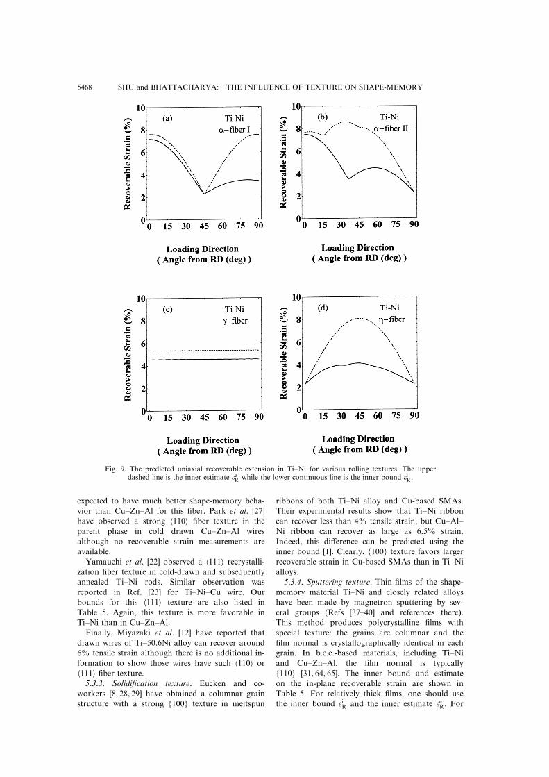
a-®ber II is not common in general, but is observedin SMAs [18, 20, 21].Figure 9 and 10 show the inner bound and esti-
mate for Ti±Ni and Cu±Zn±Al for the di�erent tex-tures listed in Table 4. Comparing these, it is clearthat the recoverable strains are much higher in Ti±
Ni than in Cu±Zn±Al for typical b.c.c. textures.The a-®ber I in Ti±Ni exhibits two peaks in RDand TD of the rolled sheet as shown in Fig. 9(a).
Therefore, this texture is desirable for uniaxial ap-plications since it is easy to extract good specimensfrom a rolled sheet. On the other hand, the g-®berobserved in Ref. [18] exhibits the least anisotropy as
seen in Fig. 9(c). This texture is preferred if therecoverable strain is required in every direction ofthe rolled sheet. In Cu-based SMAs, the shape-
recovery strain while poor in general is expected to
be relatively large for the Z-®ber. Unfortunately,
this ®ber is usually less common. We also note thatfor these alloys, the behavior of a-®ber I can beimproved by restricting the ®ber components from
{001}h110i to {112}h110i: the result is similar tothat of Fig. 10(a) except the peak of the inner esti-mate rises to about 5% around 458. Park and
Bunge [24±26] have observed this texture in a hot-rolled Cu±Zn±Al sheet although no recoverablestrain measurements are available.
5.3. Other textures
5.3.1. Random texture. The inner bound andinner estimate on the maximum recoverable exten-sion for a polycrystal with randomly oriented grainsare shown in Table 5 for Ti±Ni and Cu±Zn±Al.
The behavior of these alloys is quite similar, andrather poor with random texture.5.3.2. Wire drawing texture. Body-centered-cubic
metals and alloys have been shown to developstrong h110i ®ber texture after drawing orextrusion [63]. Assuming equal volume fraction in
all of the ®ber components, the inner bound andestimate of tensile recoverable strain in Ti±Ni andCu±Zn±Al are listed in Table 5. Clearly, Ti±Ni is
Fig. 8. Comparison of theory and experiment for the Inoue±Miwa±Inakazu textures. Here, . Expt isthe measured recoverable strain. OB, IE and IB mean outer bound eoR, inner estimate eeR and innerbound eiR, respectively: (a) PL-CR specimens with {111}huvwi texture; (b) PL-RX specimens with h110i
partial ®ber with components from {111}h110i to {110}h110i.
Table 4. Some common texture ®bers observed in b.c.c. metalsand alloys. The a-®ber II is the characteristic texture of Ti±Ni
with the B2-lattice
Fiber Fiber axis Relevant components associated with the ®ber
a-®ber I h110ikRD {001}h110i±{112}h110i±{111}h110ia-®ber II h110ikRD {111}h110i±{110}h110ig-®ber f111gkND {111}h110i±{111}h112iZ-®ber h100ikRD {001}h100i±{011}h100i
{At the same time, close agreement between the innerbound and estimate (as in Fig. 8(a)) indicates that theseare reliable predictions.
SHU and BHATTACHARYA: THE INFLUENCE OF TEXTURE ON SHAPE-MEMORY 5467
expected to have much better shape-memory beha-vior than Cu±Zn±Al for this ®ber. Park et al. [27]
have observed a strong h110i ®ber texture in the
parent phase in cold drawn Cu±Zn±Al wiresalthough no recoverable strain measurements are
available.
Yamauchi et al. [22] observed a h111i recrystalli-zation ®ber texture in cold-drawn and subsequentlyannealed Ti±Ni rods. Similar observation was
reported in Ref. [23] for Ti±Ni±Cu wire. Our
bounds for this h111i texture are also listed in
Table 5. Again, this texture is more favorable inTi±Ni than in Cu±Zn±Al.
Finally, Miyazaki et al. [12] have reported that
drawn wires of Ti±50.6Ni alloy can recover around
6% tensile strain although there is no additional in-formation to show those wires have such h110i orh111i ®ber texture.5.3.3. Solidi®cation texture. Eucken and co-
workers [8, 28, 29] have obtained a columnar grainstructure with a strong {100} texture in meltspun
ribbons of both Ti±Ni alloy and Cu-based SMAs.Their experimental results show that Ti±Ni ribbon
can recover less than 4% tensile strain, but Cu±Al±
Ni ribbon can recover as large as 6.5% strain.
Indeed, this di�erence can be predicted using theinner bound [1]. Clearly, {100} texture favors larger
recoverable strain in Cu-based SMAs than in Ti±Ni
alloys.5.3.4. Sputtering texture. Thin ®lms of the shape-
memory material Ti±Ni and closely related alloys
have been made by magnetron sputtering by sev-
eral groups (Refs [37±40] and references there).This method produces polycrystalline ®lms with
special texture: the grains are columnar and the
®lm normal is crystallographically identical in each
grain. In b.c.c.-based materials, including Ti±Niand Cu±Zn±Al, the ®lm normal is typically
{110} [31, 64, 65]. The inner bound and estimate
on the in-plane recoverable strain are shown in
Table 5. For relatively thick ®lms, one should usethe inner bound eiR and the inner estimate eeR. For
Fig. 9. The predicted uniaxial recoverable extension in Ti±Ni for various rolling textures. The upperdashed line is the inner estimate eeR while the lower continuous line is the inner bound eiR.
SHU and BHATTACHARYA: THE INFLUENCE OF TEXTURE ON SHAPE-MEMORY5468

very thin ®lms, one should use the inner bound
eifR. It turns out that they are the same for {110}
®lms for both Ti±Ni and Cu±Zn±Al. The predic-
tion is consistent with the experimental obser-
vation: around 2±3.5% recoverable strain in
sputter-deposited Ti±Ni thin ®lms [37, 40]. Thus,
{110} ®lm texture is not a favorable texture in
either Ti±Ni or Cu±Zn±Al.
Table 5 also lists the results for {100}, {111} and
random ®lms. Clearly, for the best shape-memory
Fig. 10. The predicted uniaxial recoverable extension in Cu±Zn±Al for various rolling textures. Theupper dashed line is the inner estimate eeR while the lower continuous line is the inner bound eiR.
Table 5. The predicted uniaxial recoverable extension for various textures. Use eiR and eeR for bulk specimens(wires, sheets, etc.) and thick ®lms and eifR for very thin ®lms
Texture Recoverable strains (%)
Ti±Ni Cu±Zn±Al
eiR eeR eifR eiR eeR eifR
random 2.3 2.3 2.3 1.3 1.7 1.7h110i wire/rod 6.0 7.5 Ð 1.3 1.7 Ðh111i wire/rod 3.9 9.6 Ð 1.7 1.7 Ð{111} ®lm/sheet 4.6 5.3 8.1 1.4 1.9 5.9{100} ®lm/ribbon 2.3 2.3 2.3 4.6 7.1 7.1{110} sputtered ®lm 2.3 2.3 2.3 1.5 1.7 1.7
SHU and BHATTACHARYA: THE INFLUENCE OF TEXTURE ON SHAPE-MEMORY 5469

Fig. 11. The predicted recoverable torsion vs the applied extension in Ti±Ni and Cu±Zn±Al polycrystalswith random texture as well as h110i and h100i ®ber texture. Above torsion means normalized twistor outer radius times the angle of twist. Also, IE and IB are the inner estimate geR and inner bound giR,
respectively.
SHU and BHATTACHARYA: THE INFLUENCE OF TEXTURE ON SHAPE-MEMORY5470

behavior one should try to make {111} Ti±Ni ®lmsor {100} Cu±Zn±Al ®lms.
6. RESULTS FOR COMBINED TENSION±TORSION
We now report the results for combined tension±torsion: ®rst pull the self-accommodated wire (orcircular tube) specimen to the desired strain e0below the transformation temperature, and measurethe twist angle using the thermal cycling test underthe constant torque. Figure 11 shows the results for
a random polycrystal and for a wire or tube withh110i or h100i texture. Notice that the maximumrecoverable normalized twists are relatively small.
Further, the recoverable twist decreases withincreasing imposed recoverable extension in randomand h110i texture while h100i texture shows the
opposite behavior. Sittner et al. [66] have used forcecontrol to study stress-induced pseudoelasticity inCu±Zn±Al±Mn under the combined tension±tor-sion. The maximum recoverable normalized twist is
around 1% in their experiment, and it increaseswith applied tensile loading. Unfortunately they donot provide any information about the texture.
7. DISCUSSION AND CONCLUSION
We have investigated the e�ect of texture onSME. We start with a theoretical framework toquantify recoverable strain and then use inner and
outer bounds to estimate it. We demonstrate withan example that the inner bound (in the case ofcubic to orthorhombic transformation) accounts for
the intergranular constraints and consequently pro-vides a reasonable estimate for the actual recover-able strain while the outer bound ignores theseconstraints and is a large overestimate (also see
Refs [32, 53]). In the case of a cubic±monoclinictransformation, our inner bound becomes conserva-tive (because we replace the unknown set Smono
with the smaller set Sorth); so we supplement theinner bound with an inner estimate. We comparethe predictions of the inner bound and estimate
with the experimental observations of Zhao andBeyer [20, 21] as well as Inoue et al. [18].The inner bound and estimate are quite easy to
calculateÐthey can be written as linear program-
ming problemsÐand incorporate some easily mea-surable information about the texture. Therefore,these are ideal tools to study the e�ect of texture on
SME. We demonstrate this with speci®c calculationsfocused on Ti±Ni and Cu±Zn±Al. Both these alloysundergo cubic±monoclinic transformation, recover
similar strains as single crystals and are predicted torecover similar strains as random polycrystals. Yet,their observed behavior is widely varied. Figures 9
and 10 and Table 5 shed light on the striking con-trast in SME between these two alloys. The follow-ing is a list of our main conclusions andsuggestions.
. In Ti±Ni, the texture that develops during rolling,extrusion and drawing is extremely favorable
from the point of view of large recoverablestrains. In contrast, in Cu±Zn±Al and other Cu-based SMAs the texture that develops during
these processes is rather unfavorable for SME.. In Ti±Ni, the a-®ber I rolling texture has the lar-gest uniaxial recoverable strain in the RD and
TD. Thus, this texture is ideal for applicationswhich require SME in only one direction. On theother hand, the g-®ber rolling texture has rela-
tively large recoverable strains and has little in-plane anisotropy. Hence, this texture is ideal forapplications which require SME in multiple direc-tions.
. In Cu±Zn±Al and other Cu-based SMAs, theSME can be improved in rolled sheets if one canmake either the Z-®ber texture or the a-®berrestricted to {001}h110i±{112}h110i. In the latercase, relatively large recoverable strain is pre-dicted around 458 from the RD.
. {100} solidi®cation texture shows large recover-able strain for Cu-based SMAs but not for Ti±Niribbons.
. Both Ti±Ni-based and Cu-based SMAs recovercomparatively small strains in thin ®lms owing tothe unfavorable {110} or random sputtering tex-ture. Ti±Ni ®lms with {111} texture and Cu-
based SMA ®lms with {100} texture are predictedto have large recoverable strains.
. Typically, the recoverable torsion is quite small.
In wires, rods and tubes with random or h110idrawing texture, the recoverable angle of twistdecreases with increasing applied uniaxial exten-
sion while the behavior is reversed for h100i tex-ture.
We conclude with a few comments.
7.1. Other models
Various authors [17, 19] have used a model thatis equivalent to what we call the outer bound topredict the recoverable strain. This bound ignores
the constraints of neighboring grains which turnout to be very important and consequently, theirpredictions are much larger (often by a factor oftwo) than the observed recoverable strains.
Inoue et al. [18] have used a di�erent model,which they found agreed well with their obser-vations. In the language of this paper, rather than
using the set S for a single crystal, they use only asmall subset of it, the size of which is determinedby a parameter q. They then average over the
grains; in other words they use an outer boundbased on this smaller set. In the examples they con-sider, the underestimate in the single crystal for a
choice q= 0.5 in each grain compensates for theoverestimate inherent in the outer bound, and theyobtain very good agreement with experiment.However, it is unclear whether this choice gives
SHU and BHATTACHARYA: THE INFLUENCE OF TEXTURE ON SHAPE-MEMORY 5471

good results in other situations, especially for di�er-ent materials, textures and multiaxial loading.
7.2. R-phase Ti±Ni
Ti±Ni alloys often transform from the cubic to a
trigonal R-phase before transforming to the mono-clinic martensite [44, 67, 68]. This cubic±trigonaltransformation also displays SME and superelasti-
city. Though the strains are smaller, this transform-ation is often preferable compared to the cubic±monoclinic transformation in view of small hyster-
esis and ease of control [69]. According to the sym-metry arguments of Bhattacharya and Kohn [1], arandom polycrystal of cubic±trigonal material willnot display any SME. However, a polycrystalline
wire with h111i texture has about 0.9% recoverableuniaxial strain. A rolled sheet with g-®ber texturealso has a nontrivial inner bound of about 0.2%
recoverable extension in any rolling plane direction.Many shape-memory wires do possess the h111i tex-ture and once again this prediction is consistent
with observation. Thus, texture produces the goodbehavior in Ti±Ni even in the case of the R-phase.
7.3. Texture formation
Various researchers are conducting experimentsto systematically study the e�ect of texture onSME. Apart from those cited above, we report on
the interesting work of Matsumura et al. [70] onrolled sheets of Fe±Mn±Si alloys. This alloy under-goes a face-centered-cubic (f.c.c.) to hexagonal-
close-packed (h.c.p.) transformation. By extractingspecimens from di�erent parts, Matsumura et al.have found that the surface layer with a shear tex-
ture has a larger SME than the less anisotropicmid-thickness layer. This suggests an opportunity toimprove shape-memory behavior by targetingspecial textures using novel processing techniques.
AcknowledgementsÐWe are grateful for helpful discus-sions with J. Beyer, R. V. Kohn and L. Zhao. This workwas partially supported by grants from Air Force O�ce ofScienti®c Research through F49620-95-1-0109 andNational Science Foundation through CMS-9457573.
REFERENCES
1. Bhattacharya, K. and Kohn, R. V., Acta mater., 1996,44, 529.
2. Otsuka, K., Sakamoto, H. and Shimizu, K., Actametall., 1979, 27, 585.
3. Perin, P., Bourbon, G., Goo, B. C., Charai, A.,Bernardini, J. and Lexcellent, Ch., J. Physique IV,1995, 5(C2), 263.
4. Bohong, J. and Hsu, T. Y., Mater. Sci. Forum, 1990,56-58, 457.
5. Lexcellent, Ch. and Vacher, P., Arch. Mech., 1993, 45,135.
6. Sakamoto, H. and Shimizu, K., Trans. Japan Inst.Metals, 1986, 27, 592.
7. Oishi, K. and Brown, L. C., Metall. Trans., 1971, 2,1971.
8. Eucken, S. and Hirsch, J., Mater. Sci. Forum, 1990,56-58, 487.
9. Donner, P. and Eucken, S., Mater. Sci. Forum, 1990,56-58, 723.
10. Miyazaki, S., Kimura, S., Otsuka, K. and Suzuki, Y.,Scripta metall., 1984, 18, 883.
11. Saburi, T., Yoshida, M. and Nenno, S., Scriptametall., 1984, 18, 363.
12. Miyazaki, S., Otsuka, K. and Suzuki, Y., Scriptametall., 1981, 15, 287.
13. Piao, M., Otsuka, K., Miyazaki, S. and Horikawa, H.,Mater. Trans. JIM, 1993, 34, 919.
14. Saburi, T., Tatsumi, T. and Nenno, S., J. Physique,1982, 43(C4), 261.
15. Lin, H. C. and Wu, S. K., Acta metall., 1994, 42,1623.
16. Li, D. Y., Wu, X. F. and Ko, T., Acta metall., 1990,38, 19.
17. Mulder, J. H., Thoma, P. E. and Beyer, J., Z.Metallk., 1993, 84, 501.
18. Inoue, H., Miwa, N. and Inakazu, N., Acta mater.,1996, 44, 4825.
19. Kitamura, K., Miyazaki, S., Iwai, H. and Kohl, M.,Proc. Int. Conf. on Shape Memory and SuperelasticTechnologies, SMST-97, Paci®c Grove, California,1997, in press.
20. Zhao, L., Ph.D. thesis, University of Twente, TheNetherlands, 1997.
21. Zhao, L. and Beyer, J., 1998, in preparation.22. Yamauchi, K., Nishida, M., Itai, I., Kitamura, K. and
Chiba, A., Mater. Trans. JIM, 1996, 37, 210.23. Willemse, P. F., Koopman, B. J. and Beyer, J., J.
Physique IV, 1991, 1(C4), 329.24. Park, N. J. and Bunge, H. J., Z. Metallk., 1990, 81,
636.25. Park, N. J. and Bunge, H. J., J. Physique IV, 1991,
1(C4), 323.26. Park, N. J. and Bunge, H. J., Mater. Sci. Forum,
1994, 157-162, 563.27. Park, N. J., Wang, C. Q. and Bunge, H. J., Mater.
Sci. Forum, 1994, 157-162, 827.28. Eucken, S., Hirsch, J. and Hornbogen, E., Textures
Microstruct., 1988, 8-9, 415.29. Eucken, S., Donner, P. and Hornbogen, E., Mater.
Sci. Engng, 1988, 98, 469.30. Donner, P., J. Physique IV, 1991, 1(C4), 355.31. Su, Q., Hua, S. Z. and Wuttig, M., J. Alloys Comp.,
1994, 211/212, 460.32. Bhattacharya, K. and Kohn, R. V., Archs Ration.
Mech. Analysis, 1997, 139, 99.33. Shu, Y. C., Ph.D. thesis, California Institute of
Technology, 1998, in preparation.34. Saburi, T. and Nenno, S., in Proc. Int. Conf. on Solid±
Solid Phase Transformations, ed. H. I. Aaronson, D.E. Laughlin, R. F. Sekerka and C. M. Wayman. TheMetall. Soc. AIME, New York, 1981, pp. 1455±1479.
35. Kohn, R. V. and Niethammer, B., 1998, in prep-aration.
36. Krulevitch, P., Lee, A. P., Ramsey, P. B., Trevino, J.C., Hamilton, J. and Northrup, M. A., J.Microelectromech. Syst., 1996, 5, 270.
37. Ishida, A., Takei, A. and Miyazaki, S., Thin SolidFilms, 1993, 228, 210.
38. Miyazaki, S. and Ishida, A., Mater. Trans. JIM, 1994,35, 14.
39. Krulevitch, P., Ramsey, P. B., Makowiecki, D. M.,Lee, A. P., Northrup, M. A. and Johnson, G. C., ThinSolid Films, 1996, 274, 101.
40. Hou, L. and Grummon, D. S., Scripta metall., 1995,33, 989.
41. Bhattacharya, K. and James, R. D., J. Mech. Phys.Solids, 1998, to be published.
42. Chakravorty, S., Ph.D. thesis, University of Illinois atUrbana±Champaign, 1975.
SHU and BHATTACHARYA: THE INFLUENCE OF TEXTURE ON SHAPE-MEMORY5472

43. Saburi, T. and Wayman, C. M., Acta metall., 1979,27, 979.
44. Miyazaki, S., Kimura, S. and Otsuka, K., Phil. Mag.A, 1988, 57, 467.
45. Otsuka, K. and Shimizu, K., Trans. Japan Inst.Metals, 1974, 15, 103.
46. Nam, T. H., Saburi, T., Nakata, Y. and Shimizu, K.,Mater. Trans. JIM, 1990, 31, 1050.
47. Knowles, K. M. and Smith, D. A., Acta metall., 1981,29, 101.
48. Otsuka, K., Sawamura, T. and Shimizu, K., Physicastatus solidi (a), 1971, 5, 457.
49. Chakravorty, S. and Wayman, C. M., Acta metall.,1977, 25, 989.
50. Otsuka, K., Nakamura, T. and Shimizu, K., Trans.Japan Inst. Metals, 1974, 15, 200.
51. Bhattacharya, K., Cont. Mech. Thermodyn., 1993, 5,205.
52. Bhattacharya, K., Archs Ration. Mech. Analysis, 1992,120, 201.
53. Bhattacharya, K., Kohn, R. V. and Shu, Y. C., inProc. of the IUTAM Symposium on TransformationProblems in Composite and Active Materials, ed. Y. A.Bahei-El-Din and G. J. Dvorak, 1997, in press.
54. Milton, G. W., Commun. Pure Appl. Math., 1994, 47,959.
55. Shu, Y. C., Preprint, 1998.56. Saburi, T., Watanabe, Y. and Nenno, S., ISIJ Int.,
1989, 29, 405.
57. Bunge, H. J., Texture Analysis in Materials Science.Butterworth, London, 1982.
58. Miyazaki, S. and Otsuka, K., ISIJ Int., 1989, 29, 353.59. Raabe, D. and LuÈ cke, K., Mater. Sci. Forum, 1994,
157-162, 597.60. von Schlippenbach, U., Emren, F. and LuÈ cke, K.,
Acta metall., 1986, 34, 1289.61. Emren, F., von Schlippenbach, U. and LuÈ cke, K.,
Acta metall., 1986, 34, 2105.62. Mishra, S., DaÈ rmann, C. and LuÈ cke, K., Acta metall.,
1984, 32, 2185.63. Hosford, W. F., The Mechanics of Crystals and
Textured Polycrystals. Oxford University Press, NewYork, 1993.
64. Hoogeveen, R., Moske, M., Geisler, H. and Samwer,K., Thin Solid Films, 1996, 275, 203.
65. Ying, F., Smith, R. W. and Srolovitz, D. J., Appl.Phys. Lett., 1996, 69, 3007.
66. Sittner, P., Hara, Y. and Tokuda, M., Metall. Trans.,1995, 26A, 2923.
67. Miyazaki, S. and Otsuka, K., Metall. Trans., 1986,17A, 53.
68. Miyazaki, S. and Wayman, C. M., Acta metall., 1988,36, 181.
69. Otsuka, K., in Engineering Aspects of Shape MemoryAlloys, ed. T. W. Duerig, K. N. Melton, D. StoÈ ckeland C. M. Wayman. Butterworth±Heinemann,London, 1990, pp. 36±45.
70. Matsumura, O., Furusako, S., Furukawa, T. andOtsuka, H., ISIJ Int., 1996, 36, 1103.
SHU and BHATTACHARYA: THE INFLUENCE OF TEXTURE ON SHAPE-MEMORY 5473