the impact of earth cobalt permanent ... impact of rare earth cobalt permanent magnets on...
TRANSCRIPT

THE IMPACT OF RARE EARTH COBALT PERMANENT MAGNETS ON ELECTROMECHANICAL
DEVICE DESIGN
R.L. Fisher, Inland Motor Specialty Products Division P.A. Studer, Goddard Space Fl ight Center
ABSTRACT
The discovery of rare ear th cobal t magnets has introduced a new class of permanent magnets with energy products several times grea te r than heretofore available. The prospects fo r performance improvements and the miniaturization of electromagnetic devices a r e grea t .
This paper discusses spec i f ic motor designs which employ t h i s revolutionary material with special emphasis on i t s unique propert ies and magnetic f i e l d geometry. Magnetic f i e l d geometry i s an important design consideration s ince the mater ia l derives i t s high energy product from extremely high coercive force whereas f lux density is the parameter which a f f e c t s khe motor torque equation d i r ec t ly . New magnetic c i r c u i t designs a re therefore needed t o cap i t a l i ze on the poten t ia l benefi ts of t h i s material i n conventional torque motors.. The advantages of t h i s mater ia l i n the design of i ron less armature motors and l i nea r actuators are more obvious. I n addition t o performance improvements and power savings, higher r e l i a b i l i t y devices a re a t ta inable .
Both the mechanism and systems engineer should be aware of the new per- formance leve ls which a re current ly becoming avai lable a s a r e s u l t of the r a r e ear th cobal t magnets.
INTRODUCTION
The rapid advance of e lectronics has s to len most of t he headlines i n recent years with regard to miniaturization. exponential improvement i n permanent magnet mater ia ls has a l so been underway. Most large systems a r e composed of both control e lectronics and a var ie ty of electromechanical devices. I n s p i t e of a l l the advances i n microcircuitry, i n the end the desired function generally involves some physical motion o r work t o be done.
It is less w e l l recognized t h a t an
Of the large var ie ty of electromechanical devices which a re u t i l i z e d i n spacecraft and instruments, many employ permanent magnets. The design and u t i l i z a t i o n of these devices a re a f e r t i l e f i e l d f o r s ign i f icant performance improvements a s w e l l as weight and power savings i f ear ly a t ten t ion i s paid t o the design and specif icat ion of mechanisms making f u l l use of these new materials.
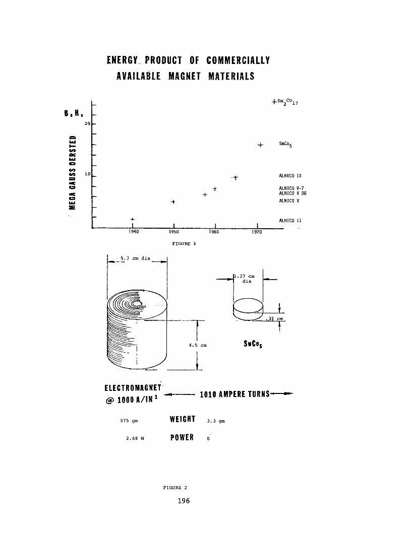
The designer of electromagnetic devices has seen the continued improvements i n the energy products of permanent magnet mater ia ls avai lable . During the 50's new alnico a l loys appeared regular ly year a f t e r year with an even more rapid rise with the development of d i rec t iona l cooling techniques i n the presence of a magnetic f i e l d . For a few years t h i s rapid progress seemed t o have leveled off u n t i l the dramatic discovery of rare ear th cobalt a l loys and the commercial introduction of SmCo5 and more recent ly Sm2Co17 (Fig. 1).
195
https://ntrs.nasa.gov/search.jsp?R=19790014384 2018-05-23T01:10:49+00:00Z
2 0
10
ENERGY ~ R O D U C ~ OF COM AvAlLalgLe ACNET MATERIALS
- - - - -
ALNICO IX
- ALNICO V-7 ALNICO V DG
ALNICO V -
+ - - + ALNICO I1 I I I I
+sm Co 2 17
FIGURE 1
4 . 5 cm
-+ + +
+ SmCo5
SHCO,
E LE CTR 0 MAC N E T @ 1000 A / I N * - 1010 AMPERE TURNS-
5 7 5 gm WEIGHT 3 . 3 gm
2 . 6 8 W POWER 0'
F I G U R E 2
196

This exponential increase i n permanent magnet cha rac t e r i s t i c s has continued t o broaden the range of appl icat ions to which electromagnetic devices can be e f fec t ive ly employed. modern r a r e ear th magnets compared t o an electromagnet.
Figure 2 shows the dramatic s i z e and weight savings of
Rare ear th magnets a r e having a profound impact on the performance of electromechanical devices. Despite the obvious advantage of t h e i r higher energy product ( 6 H max) usually expressed i n mil l ions of gauss oers teds a con- s iderable amount of engineering is required t o make ef fec t ive use of t h e i r po ten t ia l . The fundamental reason f o r t h i s i s t h a t t he improvement is i n t h e coercive force ra ther than f lux density.
Figure 3 shows the magnetic propert ies of the most commonly used alnico magnet mater ia ls and some of the rare ear th mater ia ls . A s can be seen, there is qui te a difference i n the magnetic charac te r i s t ics . I t is not possible to obtain improved motor performance by merely subst i tut ing r a r e ear th magnets i n place of a ln ico magnets. The motor must be designed t o exploi t the character- i s t ics of the par t icu lar magnet material . I f you consider the basic equation f o r the force or torque developed by a motor it i s only the a i r gap f lux densi ty r a the r than the coercive force which has a d i r e c t e f f e c t on the per- formance. The challenge t o the device designer then is t o u t i l i z e t h i s high coercive force most e f fec t ive ly to produce a more e f fec t ive , higher performance, l i gh te r weight, and/or more cos t e f fec t ive mechanism.
Alnico 5-7 - Alnico 5 -
Coercive Force - H - Kilo Oersteds Figure 3 - Typical Magnetic Froperties
197

DEVICES U S I N G WRE EARTH MAGNETS
DC Torque Motors
A DC torque motor is an electromagnetic actuator which can be attached Most torque motors a r e provided a s frameless u n i t s con- d i r e c t l y t o the load.
s i s t i n g of a wound ro to r assembly, a permanent magnet s t a t o r assembly, and a brush r ing assembly. They are usual ly t h i n i n axial length compared w i t h diameter, and have a r e l a t ive ly large bore through the ro tor f o r d i r ec tmoun t iq on the load shaf t . A DC torque motor i s designed to provide the highest torque p rac t i ca l f o r t he s i ze , weight and power avai lable while providing smooth control i n a high response system.
The key t o improved DC torque motor performance is improved permanent magnet mater ia ls . Figures 4 and 5 depic t t he construction of motors with a ln ico magnets and with rare ear th magnets. to-area r a t i o because of the low coercive force. slope f o r an alnico 5-7 magnet w e r e t o f a l l below 18 cgsu, the magnetic f lux would be reduced due t o permanent demagnetization of the magnet. Therefore, much care must be taken i n keepering the s t a t o r assembly during handling and assembly, and to insure t h a t current spikes a re controlled so as not to cause demagnetization.
Alnico magnets need a large length- For example, i f the operating
The a ln ico torquers a r e constructed with two magnets feeding one pole piece i n order t o keep a large length-to-area r a t i o . Anywhere from one-third t o one-half t h e t o t a l magnetic f lux i s l o s t as leakage f lux. assembly must be mounted i n a non-magnetic housing t o prevent the housing from shunting the magnetic f lux.
The s t a t o r
Figure 4
Alnico Magnet Construction
Figure 5
Rare Earth Magnet Construction
198

The rare earth magnets have less induction but a much larger coercive
With this force than the Alnico magnets. Therefore, a much smaller length-to-area ratio is possible, allowing the construction shown in Figure 5. configuration, the housing can be either magnetic or non-magnetic without affecting performance. Only about 10% of the magnetic flux is lost as leak- age flux. Since the permeability of the rare earth materials is very close to that of air, the inductance of the motor is reduced, resulting in lower electrical time constant. Because of the large coercive force a rare earth magnet torquer cannot be demagnetized as the result of overcurrent condi- tions. Keepering is not required for handling.
The advantages of DC torque motors having rare earth magnets are:
1. Greater peak torque capability. 2. In most cases less power required €or a given torque. 3 . No keepering required. 4. Overcurrent will not demagnetize. 5. Less electrical time constant. 6. Fewer stray magnetic fields. 7. Larger air gaps are possible, making rotor-to-stator concentricity
less critical.
Inland torquer QT-1207 with SmCo5 magnets was designed to be a direct replacement for a similar size unit which has Alnico 5-7 magnets. characteristics of the two motors are compared in Table I. Pulse currents were applied to the new design to avoid overheating at the large values of current, and the output torque measured with a torque transducer. At 0.282 Nm (40 oz.in) peak torque (double the peak torque rating), the torque sensitivity was reduced by only 11%. high current pulses.
The
No demagnetization resulted from the
TABLE I
CHARACTER1 ST ICs T- 12 18A QT-1207A UNITS
Magnet material Alnico V-7 SmCog
Peak torque rating 106 141 (18 MGOe)
Power input at 106 mNm 63 46 watts
Motor constant 13.4 15.6 m N m / & z G
Static friction 3.5 4.9 m m
Motor weight 65 65 g
Torque sensitivity 84.7 98.9 mNm/A
DC resistance 40.0 40.0 ohms
Inductance 12 7.9 mH
199

Table I1 compares t h e performance of three Inland torque motors; one with a l n i c o 8 magnets, one wi th SmCo5 magnets (18 MGO,), and one with ( S P P ~ E O ~ rnagnets (26 MGO,). The SmCo5 u n i t develops 29% more torque than t h e a l n i c o u n i t and t h e (SmPr) Cog u n i t 48% more.
TABLE I1
CHARACTERISTICS
Magnet material
Peak torque r a t i n g m
Power input , s t a l l e d w a t t s
Motor cons tan t NnlI4izEF
S t a t i c f r i c t i o n m
Torque s e n s i t i v i t y m/A
DC r e s i s t a n c e O h S
Inductance , mH
T-2405A QT-24 02A
Alnico 8 SmCog
3.39 4.38 (18 MGO,)
285 261
0.20 0.27
0.07 0.11
0,339 0.438
2.85 2.61
5.0 2.7
.._ QT-2403A
( S m r ) Cog (26 MGO,)
5.01
261
0.31
0.11
0.501
2.61
2.7
Ironless Armature Torque Motors
One type of motor of p a r t i c u l a r i n t e r e s t t o t h e aerospace mechanism and instrument designer is t h e i r o n l e s s armature motor. The advantage of t h i s type of motor i s t h e complete e l imina t ion of breakway f r i c t i o n caused by h y s t e r e s i s and cogging due t o t h e i n t e r a c t i o n of d i s c r e t e po le s and slots i n t h e usua l motor lamination, For c e r t a i n app l i ca t ions such as p o s i t i o n con t ro l se rvo loops, t hese non-linear e f f e c t s can r e s u l t i n a fundamental l i m i t a t i o n on achievable prec is ion . I r o n l e s s armature motor cons t ruc t ion e l imina tes a l l h y s t e r e s i s , cogging, and s ta t ic fo rces between r o t o r and s t a t o r . This i s accomplished by combining a l l of t h e "iron" s t r u c t u r e with the permanent magnet assembly and i n s e r t i n g t h e armature conductors i n t o t h e a i r gap. These motors a l s o have an order of magnitude lower armature inductance s i n c e t h e motor windings are e s s e n t i a l l y an air-core wi th in t h e a i r gap. Of necess i ty , l a rge coercive f o r c e is requi red t o produce high f l u x d e n s i t i e s i n an a i r gap l a r g e enough t o accommodate many conductors of adequate cu r ren t car ry ing c a p a b i l i t y . t o t h e advent of rare e a r t h magnets, t h e use of t h i s type of motor w a s genera l ly r e s t r i c t e d t o high performance servos with s t a t iona ry magnet assemblies where the weight of t h e magnet assembly w a s not c r i t i c a l (Fig. 6 ) .
P r i o r
200

MAGNET ASSEMBLIES FOR AIR CORE ARMATURES
ALNICO Gap volume 5 cm3 Weight 1 . 2 5 Kg
3 Gap Volume 1 2 . 3 cm Weight 0.25 Kg
S W c O s
Samarium cobaltmagnets however have made it feas ib l e t o d ra s t i ca l ly reduce the weight of t h e magnet assembly and to r o t a t e the magnet assembly with only the windings s ta t ionary. armature motor is only 20% of the total motor weight.
The non-rotating m a s s of a typi’cal i ron less
The m o s t e f fec t ive use of rare ear th magnets i n t h i s case is t o bring t h e face of t he magnet d i r e c t l y t o the a i r gap with the magnet i t s e l f forming the pole. magnet volume) while supplying f lux across an a i r gap nearly equal t o t h e i r length i n the d i rec t ion of magnetization. adequately sized conductors t o be inser ted i n the gap achieving good power rat ings.
These magnets can operate a t t he i r peak energy product (minimizing
This allows a large number of
201

I n a react ion wheel the magnet assembly can be b u i l t i n t o the wheel near the rim w h e r e i t s mass contr lbutes t o the necessary i n e r t i a leading to a very substant ia l weight reduction. I n other applications the elimination of motor induced disturbances is even more important. with the advent of extremely narrow beam widths f o r communication l inks, the elimination of hysteresis and preferred posi t ion is v i t a l . been applied successfully t o f rac t iona l arc second pointing systems and are being applied t o the Space Sextant. an opt ica l encoder t o develop a microprocessor based programmable stepper* with an order of magnitude grea te r resolut ion than rea l izable with mechanically defined steps. This machine r e t a ins the advantages of fas t s l e w rates and servo damped behavior of a t rue torque motor. a system which behaves exactly as h i s l inear analysis has predicted it should, even around nul l . A multi-axis and a l l - d i g i t a l controller** has more recently been developed which is being integrated with i ron less armature motors for the Spacebore Geodetic Ranging System. This w i l l snap a laser beam from t a rge t t o t a rge t on each orbital pass to de tec t ear th f a u l t motions. The i ronless armature motor f o r t h i s system is shown i n Figure 7.
W3th advances i n sensors, especial ly
These motors have
They have been used i n conjunction with
The servo designer a t l as t has
Figure 7 - I ronless Armature Motor
*Programmable Step Scan, NAS5-24048 **All Dig i ta l Controller, NAS5-24199
202

Linear DC Force Motor
A l i n e a r DC fo rce motor developed r ecen t ly a t Inland is another example of t h e use of rare e a r t h magnets. The magnet assembly is the moving m e m b e r or s l i d e r . Therefore t h e s ize and weight of t h e magnets are important. Inland model FM-1901 develops a fo rce of 245 newtons (55 l b s ) with a s l i d e r weight of only 2.45 Kg (5.4 l b s ) .
The l i n e a r f o r c e motor c o n s i s t s of a s t a t i o n a r y winding assembly and a s l i d e r . The windings are commutated through brushes which are a t tached t o the s l i d e r .
The s l i d e r conta ins four SmCog magnets, t w o on e i t h e r s i d e of t he stator assembly. The t w o sets of magnets are mechanically connected toge ther . The s l i d e r also has brushes for commutation and brushes t o b r ing t h e inpu t power f r o m t h e stator t o t h e s l i d e r .
The s t a t o r conta ins a lamination core , windings, commutator, and t w o power rails. The windings are arranged so t h a t only t h e windings under t h e magnet assembly are energized.
This p a r t i c u l a r model w a s designed f o r a t o t a l t r a v e l of 429mm (16.9 in) . The t r ave l can be modified by changing t h e length of t h e stator assembly without a f f e c t i n g t h e motor performance. The performance parameters are shown i n T a b l e 111.
TABLE I11 LINEAR FORCE MOTOR (FM-1901)
PERFORMANCE CHARACTERISTICS Peak Force (Fp) 245 N (55 IbS) Power Input a t Peak Force @ 25OC 570 w a t t s N o Load Speed @ V p 226 c m / s (89 in / s ) Electrical T i m e Constant 4.6 m s S t a t i c F r i c t i o n 5.6 N (1.25 lb)
Theore t i ca l Max. Accelerat ion Ripple Force (average t o peak) 4.5%
9936 c m / s 2 (326 f t / s 2 )
WINDING PARAMETERS Voltage @ Fp Force S e n s i t i v i t y DC Resis tance @ 25O
29.3 v o l t s (Vp) 12.6 N/A (2.82 I b / A ) 1.5 - + 0.2 ohms
DIMENSIONS STATOR (Winding Assembly) SLIDER (Magnet Assembly) Height 48.3 mm (1.90 i n ) 94.0 mm (3.70 i n ) Width 98.3 mm (3.87 i n ) 118 mm (4.65 i n ) Length 604 mm (23.8 i n ) 175 mm (6.90 i n ) Trave 1 429 mm (16.9 i n ) Weight 14.4 Kg (31.7 l b s ) 2.45 Kg (5.40 lbs)
203

DC Tachometer
Rare ea r th magnets have a l so been u t i l i zed t o good advantage i n DC
The tach is normally connected to a high tachometers, l a rge demagnetizing currents , impedance load. and to have a l o w r ipp le voltage.
Unlike the DC motor, a tachometer does not have t o withstand
The main object ives a r e to provide a high voltage s e n s i t i v i t y
Since r a r e ear th magnets have very low magnetic leakage, it is possible t o reduce the f lux i n the commutation zone, a l s o helps reduce f lux changes due t o reluctance changes with rotat ion. r e s u l t s i n reduced r ipp le voltage.
The high coercive force of the magnets This
Recently a tachometer with alnico magnets w a s redesigned with SmCo5 magnets. A s a r e s u l t , w e obtained a 25 percent increase i n voltage sens i t i v i ty , r i pp le voltage w a s reduced by one th i rd . Additionally it does not require keepers f o r assembly.
MAGNETIC BEARINGS
A s ear ly as 1970 GSFC introduced permanent magnets i n t o magnetic bearings i n order t o minimize power consumption. This ear ly attempt u t i l i zed a pair of cy l indr ica l alnico magnets, each 4 c m i n diameter and 2 cm i n length. The advent of rare ea r th cobal t magnets has made magnetic bearings vas t ly more f eas ib l e f o r space applications on both a power and weight basis . For example, a recent magnetic bearing* used a s ing le 3 cm diameter by .65 cm SmCo5 magnet f o r 3 axis support. The use of permanent magnets i n magnetic bearings permits the establishment of high f lux dens i t i e s i n the a i r gap which i n turn allows the ampere-turn requirement of the control windings t o be grea t ly reduced. The curve i n Fig. 8 shows the force per unit, area produced p lo t ted versus f lux densi ty . Since the force is a function of the square of t he f lux densi ty , s izeable forces would require subs tan t ia l ampere-turns from a pure electro- magnet. The tradeoff between rmmber of turns and high currents both lead t o undesireable e f f ec t s . A high number of turns leads t o poor speed of response and compromises dynamic response while high currents r e s u l t i n power diss ipa- t i o n and thermal problems. Permanent magnets can be u t i l i z e d t o e s t ab l i sh a high f lux densi ty which allows a smaller control s ignal to modulate the ne t force. A desireable by-product i s that the force becomes a l inear function of the control current.
A pa r t i cu la r ly e f fec t ive way of using samarium cobal t is i l l u s t r a t e d by the control lable permanent magnet biased electromagnet i n Fig. 9. A se t of these magnets a t 3 points supported a 1 .5 meter diameter momentum wheel j o in t ly developed f o r t he Goddard Space F l ight Center and Langley Research Center i n 1974. The volume of magnet mater ia l w a s only 2.6 cm3 i n each of these permanent magnet biased electromagnet modules. The angular posit ioning of the magnets afforded f lux focusing and a low reluctance t o control f lux . With the magnet a t a 30 degree angle, the f lux density i n the i ron is t w i c e t h a t of t he permanent magnet and i ts reluctance t o control f l ux i s only half of what it would otherwise have been.
204 *NASA TM78048

FORCE l f l l l l lTlPLlCATlON N BY P.M. BIASING a5 \ u ur 3: 0 l-
Y z L
FZ25.5 ii / i i t.21 -- rAFz3.2
i
P.M. BIASED
E L E C T R O M A G N E T MODULE FIGURE 9
205

Magnetic bearings o f f e r the spacecarft mechanism and instrument designer several new freedoms. without l i fe - l imi t ing r e s t r i c t i o n s of lubr ica t ion i n vacuum and without some of the speed l imit ing f ac to r s which restrict the power densi ty of ro ta t ing devices. The suspension dynamics, including damping, can be e lec t ronica l ly control led, Only one magnetically suspended systm i s knownto be operating i n space. magnetically suspended wheels i n t o communications s a t e l l i t e s and NASA is developing a vernier pointing platform f o r Shut t le based instruments.
Active electromechanical systems can be designed
However, t he European Space Agency is planning to introduce
CONCLUSION
The order of magnitude improvement i n permanent magnet energy products has spawned a whole new generation of electromechanical devices. These span the whole f i e l d from torque motors which a r e used rout inely f o r countless applica- t ions t o special purpose devices and even t o t a l l y new mechanisms. The improvements are dramatic i n terms of power and weight savings but even more s ign i f i can t i n performance.
Aerospace instrument and systems engineers are l i ke ly t o p r o f i t most from these new developments. Y e t the automobile industry, a l s o currently interested i n shaving pounds, w a s w e l l represented a t the las t R.E.-Cobalt magnet workshop. General Motors engineers showed t h a t t o t a l costs could be reduced with the use of advanced and r e l a t ive ly expensive high energy magnets when t h e t o t a l system cost including power supply, s t ruc ture , e t c . was considered.
I t is hoped t h a t t h i s paper w i l l assist the mechanism designer to see some of t he p o s s i b i l i t i e s and challenges of designing with t h i s new material by affording some ins ight i n t o key aspects of some successful designs. A s these developments become mature products a wider knowledge of t h e i r ava i l ab i l i t y and charac te r i s t ics is needed by instrument and spacecraft systems designers.
REFERENCES
1, B. R. Patel, "Mischmetal Rare Earth Magnet Tradeoffs i n Automotive A c c e s - sory Motors," Third Internat ional Workshop on Rare Earth-Cobalt Permanent Magnets, 1978
2. David T. Curry, "Rare-Earth Magnets Power New Actuators," Machine Design, September 7, 1978
3. S. Noodleman, "Application of R a r e Earth Magnets t o D.C. Machines," Second Internat ional Workshop on R a r e Earth-Cobalt Permanent Magnets, 1976
4. P. A. Studer, "New Type Torque Motor," Second Internat ional Workshop on Rare Earth-Cobalt Permanent Magnets, 1976
5. R. J. Parker, "Rare Earth Permanent Magnets - Their Propert ies and Potent ia l Impact on Magnetoelectric Device Technology," Third European Conference on Hard Magnetic Materials, 1974
206