the ieee 1812 trial-use guide for testing pm machines virtual testing developments ·...
TRANSCRIPT

SPARK Introduction | February, 2016 | 1
The IEEE 1812 Trial-Use Guide for Testing PM Machines –
Virtual Testing Developments
Dan M. Ionel, Ph.D., IEEE Fellow [email protected]
CWIEME Berlin, May 10, 2016

SPARK Laboratory
PM Machine Testing | CWIEME Berlin, May 2016 | 2
Dan M. Ionel is Professor of Electrical Engineering and L. Stanley Pigman Chair in Power at University of Kentucky in Lexington, KY. Previously, he held dual appointments in industry, as Chief Engineer with Regal Beloit Corp and before as Chief Scientist with Vestas Wind Turbines, and in academia, as Visiting and Research Professor with University of Wisconsin and Marquette University in Milwaukee, WI. Dr. Ionel has more than 25 years of engineering experience and has designed electric machines and drives with power ratings between 0.002 and 10,000hp. He holds more than 30 patents and has published more than 100 journal and conference papers, including two winners of IEEE best paper awards. Dr. Ionel is an IEEE Fellow, the Chair of the IEEE Power and Energy Society Electric Motor Subcommittee, and the General Chair of the 2017 anniversary edition of the IEEE IEMDC Conference. [email protected]
Dr. Dan M. Ionel

SPARK Laboratory
PM Machine Testing | CWIEME Berlin, May 2016 | 3
SPARK and PEIK at University of Kentucky
• UK enjoys a longstanding tradition in electric machines and drives • Early developments on linear and PM motors, and vector control • Many learned machines using the Nasar and Boldea classic books
• PEIK - Power and Energy Institute of Kentucky, launched with large DOE grant in 2010 • Core faculty in electric power engineering and many others in related fields • Endowment established and inaugural L. Stanley Pigman Chair started in 2015 • On-going research on electric machines and drives, power electronics and systems,
renewable and alternative energy technologies • SPARK and other laboratories • Motor Design Ltd. and ANSYS Inc. strategic partnerships.

SPARK Laboratory
PM Machine Testing | CWIEME Berlin, May 2016 | 4
Outline
• IEEE 1812 “IEEE Trial-Use Guide for Testing Permanent Magnet Machines”
• Status review, based on WG reports and published Guide
• WG Past Chair, Dr. H. Karmaker; MSC Chair, Dr. Dan M. Ionel
• Special thanks to Dr. Karmaker for his contributions to the first section of this presentation
•Developments for equivalent circuit parameters and losses • PE converter controls
• DQ inductances
• Separation of losses
•Related developments - “Virtual testing” • High fidelity models and reduced order models
• Hardware in the Loop (HIL) and Real Time Digital Simulation (RTDS).

SPARK Laboratory
PM Machine Testing | CWIEME Berlin, May 2016 | 5
Outline
• IEEE 1812 “IEEE Trial-Use Guide for Testing Permanent Magnet Machines”
• Status review, based on WG reports and published Guide
• WG Past Chair, Dr. H. Karmaker; MSC Chair, Dr. Dan M. Ionel
• Special thanks to Dr. Karmaker for his contributions to the first section of this presentation
•Developments for equivalent circuit parameters and losses • PE converter controls
• DQ inductances
• Separation of losses
•Related developments - “Virtual testing” • High fidelity models and reduced order models
• Hardware in the Loop (HIL) and Real Time Digital Simulation (RTDS).

SPARK Laboratory
PM Machine Testing | CWIEME Berlin, May 2016 | 6
IEEE 1812 Purpose
•There are many differences in testing the performance characteristics of PM and non-PM machines
• In PM machines, excitation cannot be turned off and controlled similar to electrically excited machines
•There is no known guide or standard for testing PM machines.
SPARK Laboratory
PM Machine Testing | CWIEME Berlin, May 2016 | 7
IEEE 1812 Scope (1/2)
The scope of the Guide as approved by the IEEE Standards Board is as follows:
•The guide contains instructions for conducting tests to determine the performance characteristics and parameters of permanent magnet (PM) machines
•The tests may be applied to both motors and generators
•This guide covers only general test methods characteristic to PM machines
•The test methods should be applicable to the PM machines of different sizes and configurations
•… continued ...

SPARK Laboratory
PM Machine Testing | CWIEME Berlin, May 2016 | 8
IEEE 1812 Scope (2/2)
The scope of the Guide as approved by the IEEE Standards Board is as follows:
•… continued …
•The guide shall not cover all possible tests or tests of a research nature
•The tests covered by other applicable standards are not covered in this guide
•This “trial-use” guide shall not be interpreted as requiring any specific test in a given transaction or implying any guarantee as to the specific performance indices or operating conditions.
SPARK Laboratory
PM Machine Testing | CWIEME Berlin, May 2016 | 9
Working Group (WG) for IEEE 1812
•A new IEEE Power and Energy Society (PES) WG was formed by the Motor Subcommittee (MSC) of the Electric Machinery Technical Committee (EMC) in July 2009
• Original WG Chair, now WG Past Chair, Dr. Haran Karmaker
• Current MSC Chair, Dr. Dan M. Ionel
•The proposed project was approved for a trial-use guide in December 2009 by IEEE Standards Board with the expiration date of December 31, 2013
•The IEEE Industry Applications Society started to co-sponsors the project in May 2011
•The IEEE 1812 Trial-Use Guide was approved in Dec 2014
•The final WG comprised 23 members, 16 being from industry.

SPARK Laboratory
PM Machine Testing | CWIEME Berlin, May 2016 | 10
IEEE Working Group

SPARK Laboratory
PM Machine Testing | CWIEME Berlin, May 2016 | 11
IEEE 1812 Overview
•WG 1812 followed the structure of the most current edition of IEEE 115-2009 “IEEE Guide for Test Procedures for Synchronous Machines: Part I – Acceptance and Performance Testing ; Part II – Test Procedures and Parameter Determination for Dynamic Analysis” to prepare the new draft for the guide
•Following the IEEE 115 structure, IEEE 1812 was drafted for
•Part I – Test Procedures
•Part II – Machine Characteristics
• According to the IEEE style guide, the first two clauses are:
•Clause 1 – Overview
•Clause 2 – Normative References
•The guide consists of a total of six (6) clauses.

SPARK Laboratory
PM Machine Testing | CWIEME Berlin, May 2016 | 12
IEEE 1812 Overview (Contd.)
•Clause 3 - Condition and integrity tests, i.e. resistance measurement, phase sequence, insulation resistance, dielectric and partial discharge, polarity for magnets, shaft and bearing currents, over-speed tests, resistance to demagnetization, acoustic noise, vibration
•Clause 4 - Steady-state tests, i.e. open-circuit (back emf, losses, and cogging torque), short-circuit, load, thermal performance
•Clause 5 - Transient tests, i.e. retardation (or coast-down), sudden short-circuit (three phase and two phase)
•Clause 6 - Machine operating characteristics, i.e. stator voltage waveform, losses and efficiency, thermal capability, torque ripple.

SPARK Laboratory
PM Machine Testing | CWIEME Berlin, May 2016 | 13
Example – Dynamic Cogging Torque Measurement

SPARK Laboratory
PM Machine Testing | CWIEME Berlin, May 2016 | 14
Example – Static Cogging Torque Measurement

SPARK Laboratory
PM Machine Testing | CWIEME Berlin, May 2016 | 15
Example – Torque Ripple Measurement at Load

SPARK Laboratory
PM Machine Testing | CWIEME Berlin, May 2016 | 16
Example – Typical Torque Ripple Waveform

SPARK Laboratory
PM Machine Testing | CWIEME Berlin, May 2016 | 17
Example – Short Circuit Testing

SPARK Laboratory
PM Machine Testing | CWIEME Berlin, May 2016 | 18
Example – Back-to-back Load Test

SPARK Laboratory
PM Machine Testing | CWIEME Berlin, May 2016 | 19
Example – Thermal Characteristics of PM Materials

SPARK Laboratory
PM Machine Testing | CWIEME Berlin, May 2016 | 20
Example – Open Circuit Core Loss Characteristic

SPARK Laboratory
PM Machine Testing | CWIEME Berlin, May 2016 | 21
Example – Friction & Windage Loss Characteristic

SPARK Laboratory
PM Machine Testing | CWIEME Berlin, May 2016 | 22
Example - Loss Separation
Friction and windage loss • The PM rotor is replaced with a non-magnetized equivalent rotor (rotor with
PMs yet to be magnetized
• This test relies on the knowledge of the combined moment of inertia of the test machine and the drive motor
• The friction and windage loss is determined as a function of speed, if inertia and rate of change of speed are known.

SPARK Laboratory
PM Machine Testing | CWIEME Berlin, May 2016 | 23
Example – Performance Curves of PM Generator

SPARK Laboratory
PM Machine Testing | CWIEME Berlin, May 2016 | 24
IEEE 1812 Current Status
•The standard has been published as a trial-use guide on December 10, 2014 valid for 2 years
• Without a PAR to continue its revision for a full-use guide, the standard will expire in 2016
•A new initiative to form a working group is now under way with support from the Electric Machines Committees within IEEE Power and Energy and Industry Applications Societies
•Contact Dan M. Ionel, PhD, FIEEE, Professor and L. Stanley Pigman Chair in Power
Director, SPARK Laboratory – University of Kentucky
Chair, IEEE Power and Energy Society – Electric Motor Subcommittee

SPARK Laboratory
PM Machine Testing | CWIEME Berlin, May 2016 | 25
IEEE 1812 Simulation Implementation - Inductance
Isc= 𝑉𝑜𝑐
3𝑋𝑠

SPARK Laboratory
PM Machine Testing | CWIEME Berlin, May 2016 | 26
Motor-CAD Example Study for Inductance Calculation
Nissan Leaf IPM
Voc 215.15 V
Xs 0.31 Ohm
f 200 Hz
LS 0.25 mH
•Short circuit test values are tabulated
•The test could be used to determine a value of Ld
•The field distribution under motor normal operation is different to the one at short-circuit.

SPARK Laboratory
PM Machine Testing | CWIEME Berlin, May 2016 | 27
Example IEEE 1812 Simulation Implementation – Heath Run
SPARK Laboratory
PM Machine Testing | CWIEME Berlin, May 2016 | 28
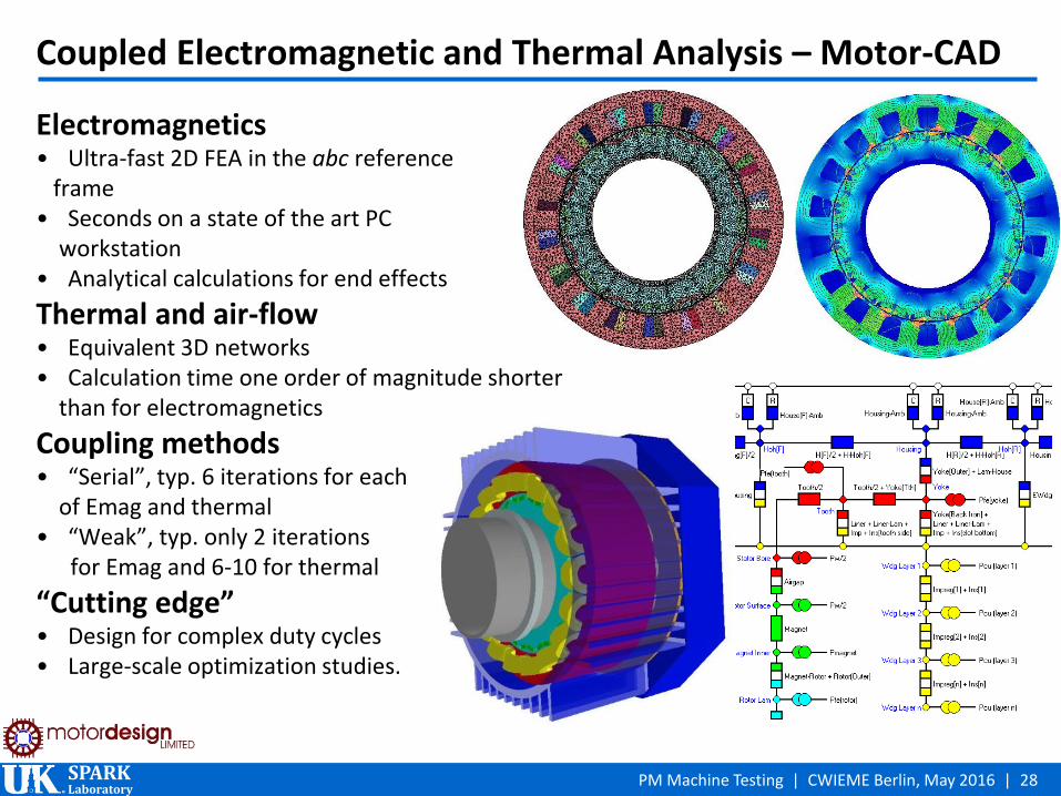
Coupled Electromagnetic and Thermal Analysis – Motor-CAD
Electromagnetics • Ultra-fast 2D FEA in the abc reference frame • Seconds on a state of the art PC workstation • Analytical calculations for end effects
Thermal and air-flow • Equivalent 3D networks • Calculation time one order of magnitude shorter than for electromagnetics
Coupling methods • “Serial”, typ. 6 iterations for each of Emag and thermal • “Weak”, typ. only 2 iterations for Emag and 6-10 for thermal
“Cutting edge” • Design for complex duty cycles • Large-scale optimization studies.

SPARK Laboratory
PM Machine Testing | CWIEME Berlin, May 2016 | 29
Outline
• IEEE 1812 “IEEE Trial-Use Guide for Testing Permanent Magnet Machines”
• Status review, based on WG reports and published Guide
• WG Past Chair, Dr. H. Karmaker; MSC Chair, Dr. Dan M. Ionel
• Special thanks to Dr. Karmaker for his contributions to the first section of this presentation
•Developments for equivalent circuit parameters and losses • PE converter controls
• DQ inductances
• Separation of losses
•Related developments - “Virtual testing” • High fidelity models and reduced order models
• Hardware in the Loop (HIL) and Real Time Digital Simulation (RTDS).

SPARK Laboratory
PM Machine Testing | CWIEME Berlin, May 2016 | 30
Example Parameters for Power Electronic Drives (VFD)
Source: YASKAWA ELECTRIC TOEP C710606 47C YASKAWA AC Drive – V1000 Quick Start Guide
Parameters required
Motor rated capacity
Motor rated current
No. of poles
Stator resistance
d-axis inductance
q-axis inductance
Back emf constant
Mandatory parameters
Optional parameters
Rated motor voltage Motor pole pair number
Rated motor current Torque constant
Rated motor power Rated magnetization/short circuit current
Rated motor speed Max. speed
Rated motor frequency
Pole position information
Optimum load angle
Moment of inertia
Resistance
Stator inductance
D-axis inductance
Reluctance torque constant
Source: SIEMENS SINAMIX S120 Function Manual 07/2007

SPARK Laboratory
PM Machine Testing | CWIEME Berlin, May 2016 | 31
Developments Considered for Inductance Measurement
•Drafted during the original development of IEEE 1812 for d and q axes measurement
•Not incorporated in the released version.

SPARK Laboratory
PM Machine Testing | CWIEME Berlin, May 2016 | 32
Equivalent Circuits for PM Machines
•Ld and Lq are functions of current components
•Cross coupling between the d and q axes is present, in principle
•Conventional equivalent circuits of PM machines do not include core losses.
Phasor diagram
d axis equivalent circuit
q axis equivalent circuit
ωλ q
Vd
LdRid
ωλ d
Vq
LqRiq

SPARK Laboratory
PM Machine Testing | CWIEME Berlin, May 2016 | 33
Inductance Measurement at Standstill
• Variable voltage supply and locked rotor at different positions
• Inductance determined as:
• 𝑅 = 𝑃
𝐼2 , 𝒁 =𝑽
𝑰 , |𝑋| = |𝑍|2 − |𝑅|2
• 𝐿𝑙𝑙=𝑋
2𝜋𝑓
• Max associated with Lq and min with Ld.

SPARK Laboratory
PM Machine Testing | CWIEME Berlin, May 2016 | 34
Alternative Methods for dq Inductance Measurements
• Standstill inductance measurements with sinusoidal or PWM voltages
• Procedure to align using the B and C phases
• Measurements using A phase
• Measurements under actual running conditions
• No load; motor driven at constant speed; Iq = 0; Id is varied; load angle is considered 0; determine Ld
• Full load; Lq; Id = 0; load angle = power factor angle; determine Lq
Alignment along d axis Alignment along q axis
Source: H. B. Ertan and İ Şahin, "Evaluation of inductance measurement methods for PM machines," International
Conference on Electrical Machines (ICEM), 2012 XXth, Marseille, 2012, pp. 1672-1678.

SPARK Laboratory
PM Machine Testing | CWIEME Berlin, May 2016 | 35
Non-linearity of Flux Linkages and Cross Coupling Effects
Flux linkages for a dq model considering saturation and cross coupling:
•Ψdd(id) – d-axis flux linkage due to d-axis current
•Ψdq(iq) – d-axis flux linkage due to q-axis current.
Source: D. M. Ionel, M. J. Balchin, J. F. Eastham and E. Demeter, "Finite element analysis of brushless DC motors for flux weakening operation“, IEEE Transactions on Magnetics, vol. 32, no. 5, pp. 5040-5042, Sep 1996.

SPARK Laboratory
PM Machine Testing | CWIEME Berlin, May 2016 | 36
Non-linearity of Flux Linkages and Cross Coupling Effects
• d –axis flux linkage:
• The PM flux:
• Both Ψdd(id) and Ψdq(iq) include contributions from the PM flux, which is subtracted, yielding two possible models:
Source: D. M. Ionel, J. F. Eastham, E. Demeter, M. J. Balchin, D.Stoia and C. Apetrei, “Different Rotor Configurations for BLDC Motors Operating in Flux Weakening Mode" in International Conference on Electric Machines, 1996

SPARK Laboratory
PM Machine Testing | CWIEME Berlin, May 2016 | 37
Non-linearity of Flux Linkages and Inductances
•Run FEA with Id = 0 and non-zero Iq and calculate the three phase flux linkages. The PM flux is obtained as:
•Run FEA with both Id and Iq non zero, and three phase flux linkages are calculated. Ld and Lq are obtained as:
Source: Peng Zang, “A Novel Design Optimization of a Fault-Tolerant AC Permanent Magnet Machine-Drive System”, PhD Dissertation, Marquette University, 2013.

SPARK Laboratory
PM Machine Testing | CWIEME Berlin, May 2016 | 38
Separation of Losses
Determination of β provides information about the different loss components of loss.
Loss at the test points
Coefficients
Source: G. Heins, D. M. Ionel, D. Patterson, S. Stretz and M. Thiele, "Combined Experimental and Numerical Method for Loss Separation in Permanent-Magnet Brushless Machines," in IEEE Transactions on Industry Applications, vol. 52, no. 2, pp. 1405-1412, March-April 2016.
Residuals

SPARK Laboratory
PM Machine Testing | CWIEME Berlin, May 2016 | 39
Separation of Losses
Philosophy – loss components have different relationships with current and speed, based on which the separation (segregation) can be performed.
Source: G. Heins, D. M. Ionel, D. Patterson, S. Stretz and M. Thiele, "Combined Experimental and Numerical Method for Loss Separation in Permanent-Magnet Brushless Machines," in IEEE Transactions on Industry Applications, vol. 52, no. 2, pp. 1405-1412, March-April 2016.

SPARK Laboratory
PM Machine Testing | CWIEME Berlin, May 2016 | 40
Outline
• IEEE 1812 “IEEE Trial-Use Guide for Testing Permanent Magnet Machines”
• Status review, based on WG reports and published Guide
• WG Past Chair, Dr. H. Karmaker; MSC Chair, Dr. Dan M. Ionel
• Special thanks to Dr. Karmaker for his contributions to the first section of this presentation
•Developments for equivalent circuit parameters and losses • PE converter controls
• DQ inductances
• Separation of losses
•Related developments - “Virtual testing” • High fidelity models and reduced order models
• Hardware in the Loop (HIL) and Real Time Digital Simulation (RTDS).

SPARK Laboratory
PM Machine Testing | CWIEME Berlin, May 2016 | 41
HIL Principles
• Real time machine model (and power electronics) for real time digital (RTDS) / hardware in the loop (HIL) simulator
• Reduced order machine models minimize the requirements for computational resources
• The controller physically exists; other combinations are also possible.

SPARK Laboratory
PM Machine Testing | CWIEME Berlin, May 2016 | 42
RTDS – Real Time Digital Simulator
• IEC 61850 communication standard for electrical substation automation systems
•GOOSE (Generic Object Oriented Substation Event) and SMV (Sampled Measured Values).
Source: RTDS Technical Documentation, 2016.

SPARK Laboratory
PM Machine Testing | CWIEME Berlin, May 2016 | 43
Example HIL from RTDS
Source: RTDS Technical Documentation: State of Electric Machine Models and their Applications in RTDS Real-Time Digital Simulator, 2016.

SPARK Laboratory
PM Machine Testing | CWIEME Berlin, May 2016 | 44
RTDS Model for PMSM
• Model based on the model for synchronous machine
• Saturation, core loss, harmonics due to back emf are neglected
Source: RTDS technical documentation VSC Permanent Magnet Synchronous Machine (PMSM), 2016

SPARK Laboratory
PM Machine Testing | CWIEME Berlin, May 2016 | 45
RTDS Input Parameters for PM Synchronous Machine
•Other parameters – initial conditions – initial rotor speed
•Voltages, currents, torque can be monitored
Mechanical parameters Electrical parameters
Source: RTDS technical documentation VSC Permanent Magnet Synchronous Machine (PMSM), 2016.

SPARK Laboratory
PM Machine Testing | CWIEME Berlin, May 2016 | 46
Simulink/Matlab Real Time
• Simscape blocks can be employed
• Input parameters for PM machine: Ld, Lq, moment of inertia, number of poles, voltage, back emf constant, rated current.
M otor M odel
Source: http://www.mathworks.com/products/simulink-real-time/
SPARK Laboratory
PM Machine Testing | CWIEME Berlin, May 2016 | 47
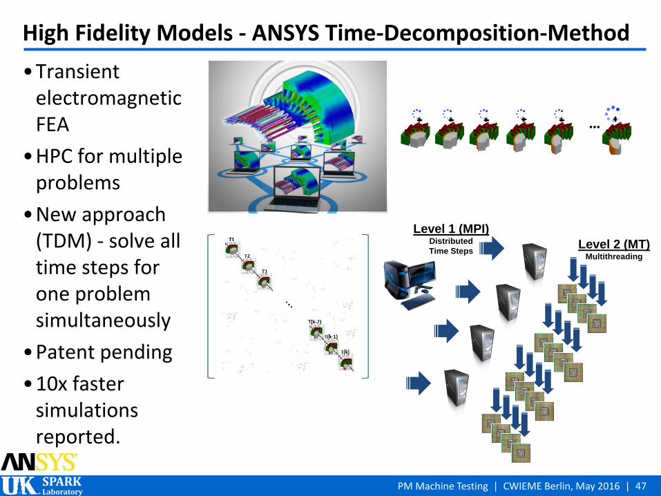
High Fidelity Models - ANSYS Time-Decomposition-Method
•Transient electromagnetic FEA
•HPC for multiple problems
•New approach (TDM) - solve all time steps for one problem simultaneously
•Patent pending
•10x faster simulations reported.
Level 1 (MPI) Distributed
Time Steps Level 2 (MT)
Multithreading
t0 t1 t2 t3 t4 tn …

SPARK Laboratory
PM Machine Testing | CWIEME Berlin, May 2016 | 48
Reduced Order Models for HIL Controls
• Systematic FEA to calculate a look-up table, e.g. phase flux linkage vs. rotor position and current
• Inputs
• currents
• rotor position
• Outputs
• flux linkages
• torque
• Lossless model example.
Source: ANSYS technical documentation on ECE Model Creation and Applications, 2015.
Current [A] 𝜃𝑖 [deg]
Flux Linkage [Wb]

SPARK Laboratory
PM Machine Testing | CWIEME Berlin, May 2016 | 49
Models Including Core (Iron) Losses
Specific core losses components in an IPM over the entire torque speed range;
estimated by FEA
Source: R. Wrobel, P. H. Mellor, M. Popescu and D. A. Staton, "Power Loss Analysis in Thermal Design of Permanent-Magnet Machines—A Review," in IEEE Transactions on Industry Applications, vol. 52, no. 2, pp. 1359-1368, March-April 2016.
SPARK Laboratory
PM Machine Testing | CWIEME Berlin, May 2016 | 50
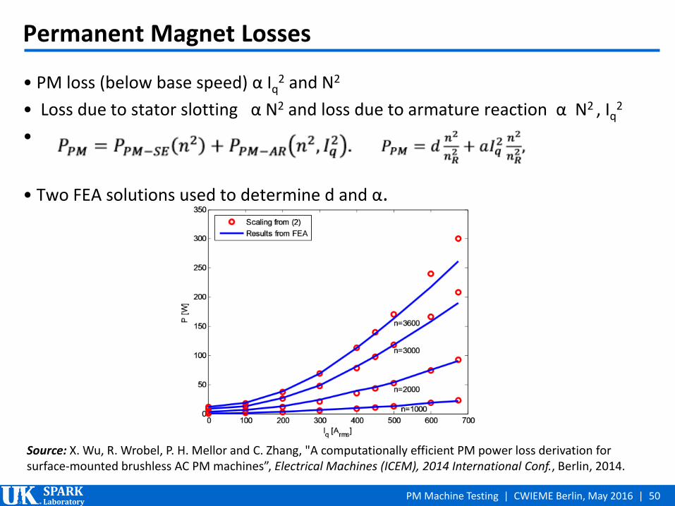
Permanent Magnet Losses
• PM loss (below base speed) α Iq2 and N2
• Loss due to stator slotting α N2 and loss due to armature reaction α N2 , Iq2
•
• Two FEA solutions used to determine d and α.
Source: X. Wu, R. Wrobel, P. H. Mellor and C. Zhang, "A computationally efficient PM power loss derivation for surface-mounted brushless AC PM machines”, Electrical Machines (ICEM), 2014 International Conf., Berlin, 2014.

SPARK Laboratory
PM Machine Testing | CWIEME Berlin, May 2016 | 51
AC Conductor Power Losses
• A function of frequency and temperature and given as
where Pdc – DC power loss, PaceffE – power loss due to AC excitation of the windings and PaceffR – winding power loss due to rotation of the rotor
• Assumption of uniform average loss distribution may yield incorrect temperature distribution.
Temperature distribution calculated from detailed loss model (left) and averaged loss model (right).
Source: R. Wrobel, P. H. Mellor, M. Popescu and D. A. Staton, "Power Loss Analysis in Thermal Design of Permanent-Magnet Machines—A Review," in IEEE Transactions on Industry Applications, vol. 52, no. 2, pp. 1359-1368, March-April 2016.

SPARK Laboratory
PM Machine Testing | CWIEME Berlin, May 2016 | 52
Coupled Model in Motor-CAD and Motor-LAB
•Electromagnetic FE analysis, including losses
•Thermal calculations with equivalent circuit networks
•Steady state, transient, and complex duty cycles.
Motor-LAB
Motor-CAD EMag
Motor-CAD Therm
Source: MDL technical documentation Modelling the Nissan LEAF Electric Motor, 2015.

SPARK Laboratory
PM Machine Testing | CWIEME Berlin, May 2016 | 53
Reduced Node Thermal Model
• Very useful for complex (full) system simulation… provided satisfactory accuracy • Matrix reduction method to calculate a smaller R-C network that gives same
transient thermal response • Keep enough nodes to give good indication of temperatures across entire model • Full model of 65 nodes versus 7 nodes in reduced model • Accuracy within 1% and 7 times reduction in computational time.
Source: MDL technical documentation Modelling the Nissan LEAF Electric Motor, 2015.

SPARK Laboratory
PM Machine Testing | CWIEME Berlin, May 2016 | 54
Summary and Acknowledgments
•IEEE 1812 “Trial-Use Guide for Testing Permanent Magnet Machines” is now available for use
•On-going IEEE Working Group activities focus on developments for
• Equivalent circuit parameters measurements
• Separation of losses
•Other related topics include
• High fidelity models and reduced order models
• Hardware in the Loop (HIL) and Real Time Digital Simulation (RTDS)
•Special thanks to Drs. Haran Karmaker and Vandana Rallabandi for their contributions in the preparation of this presentation
•The continued support of our group’s academic research by Motor Design Ltd. and ANSYS, Inc. is gratefully acknowledged.
SPARK Laboratory
PM Machine Testing | CWIEME Berlin, May 2016 | 55
Main References
• IEEE 1812 Trial-Use Guide for Testing Permanent Magnet Machines, Dec. 2014. • H. B. Ertan and İ Şahin, "Evaluation of inductance measurement methods for PM machines,"
Electrical Machines (ICEM), 2012 XXth International Conference on, Marseille, 2012, pp. 1672-1678. • D. M. Ionel, M. J. Balchin, J. F. Eastham and E. Demeter, "Finite element analysis of brushless DC
motors for flux weakening operation," in IEEE Transactions on Magnetics, vol. 32, no. 5, pp. 5040-5042, Sep 1996.
• D. M. Ionel, J. F. Eastham, E. Demeter, M. J. Balchin, D.Stoia and C. Apetrei, “Different Rotor Configurations for BLDC Motors Operating in Flux Weakening Mode“, in International Conference on Electric Machines, 1996.
• Peng Zhang, “A Novel Design Optimization of a Fault-Tolerant AC Permanent Magnet Machine-Drive System”, PhD Dissertation, 2013.
• G. Heins, D. M. Ionel, D. Patterson, S. Stretz and M. Thiele, "Combined Experimental and Numerical Method for Loss Separation in Permanent-Magnet Brushless Machines," in IEEE Transactions on Industry Applications, vol. 52, no. 2, pp. 1405-1412, March-April 2016.
• R. Wrobel, P. H. Mellor, M. Popescu and D. A. Staton, "Power Loss Analysis in Thermal Design of Permanent-Magnet Machines—A Review," in IEEE Transactions on Industry Applications, vol. 52, no. 2, pp. 1359-1368, March-April 2016.
• X. Wu, R. Wrobel, P. H. Mellor and C. Zhang, "A computationally efficient PM power loss derivation for surface-mounted brushless AC PM machines," Electrical Machines (ICEM), 2014 International Conference on, Berlin, 2014, pp. 17-23.
• ANSYS technical documentation on ECE Model Creation and Applications, 2015. • RTDS technical documentation: State of Electric Machine Models and Their Applications in RTDS
Real-Time Digital Simulator, 2016.

SPARK Laboratory
PM Machine Testing | CWIEME Berlin, May 2016 | 56
Invitation for Participation
• IEEE 1812 Test Guide WG • In-person formal meetings at IEEE PES Jul 2016 and IEEE IEMDC May 2017
• Update planned for Coil and Winding Expo, Chicago, Oct 2016
•“Virtual testing” initiative • Forum for discussion and collaboration
• SPARK Lab at University of Kentucky serves as main sponsor
• Current supporters include ANSYS and Motor Design Ltd. with others, such as RTDS, Toshiba expressing interest
• Inaugural in-person meeting proposed for the Coil and Winding Expo in Chicago, IL in October 2016
•Contact Dan M. Ionel, PhD, FIEEE, Professor and L. Stanley Pigman Chair in Power
Director, SPARK Laboratory – University of Kentucky
Chair, IEEE Power and Energy Society – Electric Motor Subcommittee