the great hall of the trajan markets throughout the centuries · the great hall of thetrajan...
TRANSCRIPT

Structural Analysis of Historic Construction – D’Ayala & Fodde (eds)© 2008 Taylor & Francis Group, London, ISBN 978-0-415-46872-5
The great hall of the Trajan Markets throughout the centuries
L. Ungaro & M. VittiOffice for Trajan’s Markets Museum and Imperial Forum, Rome, Italy
E. SperanzaArchitect, Rome, Italy
ABSTRACT: The paper illustrates ongoing research on the great hall of the Trajan Markets in Rome, led bythe Office of the Trajan Markets Museum. The research has been conducted during the restoration and seismicupgrading of the monuments.
The first part of the work is devoted to a description of structural layout and archaeological evidences,allowing some reconstructive hypothesis in different periods of the life of the monument. Among these, theroman configuration is examined under the point of view of its mechanical behaviour, using the method offunicular polygons. The analysis is carried out in static conditions and simulating the historical earthquakeswhich the monument (in its original configuration) undergone.
The paper discusses the structural safety margin of the Roman vault in relation to the mechanical effectivenessof different structural elements, and finally some conclusions are drawn on the present state of the Vault.
1 THE GREAT HALL OF TRAJAN’SMARKETS
1.1 Introduction to the Monument
The Great Hall of the Trajan’s Markets is one of themost impressive monuments of the Imperial Periodstill standing in the very heart of Rome.
Its architectural and structural layout, likewisethe one of the whole Complex of the Markets, isattributed to Apollodoro from Damascus, architectdirectly charged by Trajan Emperor to carry out theambitious and monumental project of Trajan Forum.
The architectonic and structural layout of the Hall isinnovative for the construction technique of the period.Previous researches on similar typological schemes inthe roman architecture carried out by several authors(Giovannoni 1913, Bianchini 1991, Lancaster 2000,Vitti 2007) have stressed the presence of signifi-cant innovations compared to other monuments of theperiod.
1.2 The Great Hall today: architectonic andstructural layout
The Great Hall is featured by a planimetric rectan-gular shape. A monumental concrete vault, spatiallyarticulated through six consecutive cross vaults, cov-ers a double-height space; the space between the pillarsis covered by barrel volts. Along both sides of the
Hall is a system of “tabernae” placed on two storeys,structurally shared by thick concrete walls.
The Vault is supported, at the second storey, by iso-lated pillars, and connected to the rest of the structureby slender arches (Figure 1, left).
The choice of materials used in the constructionprocess was made on the basis of the structural func-tion of each element as well as of the relative strengthrequired for each of them.
The seven pillars on both side of the hall are builtup using two different techniques: the lower part isrealised by two travertine ashlars blocks measuring75 × 90 × 150 cm (2,5 × 3 × 5 roman feet).
The superior block was originally shaped as a cor-bel outstanding inward the vault. At present only onecorbel is left of the original system, and this is placedon the south facade wall (Figure 1, right).
The masonry portion over the travertine blocks ismade up of roman concrete, with external red brick-work leaf, starting from a horizontal layer of bipedaleselements (59 cm, two roman feet).
The barrel vaults between pillar and pillar arerealised in concrete with different assortment fromspringing to the keystone: haunches are mainly madeup of brick fragments, while at the crown they arereplaced by lighter tuff fragments. The concrete ofthe central part of the vault is made of grey mor-tar with black aggregates and yellow tuff, used ascoementa.
1509

Figure 1. Left: view of the vault of the Great Hall. Right:south-west pillar with travertine corbel.
Figure 2. Left: sketch by Marciana Library. Right: 3dreconstruction by M. Bianchini (2003).
The original thickness of the vault to the key-stone was of 30 cm and the flat extrados was usedas terrace with an articulated waterproofing system(Ungaro-Vitti 2001).
1.3 The Great Hall through the centuries
The original layout of the Roman vault can be recon-structed through archaeological data and, most of all,through old paintings and sketches as those by GiulioRomano (Lapidazione di S. Stefano 1520–1546), Sal-lustio Peruzzi (Florence, Uffizi Museum XVIth cen-tury), and one more preserved in the Marciana Library(XVIth) (Figure 2, left).
Indications and evidences provided by this researchtype, critically analysed and put side by side, enableto formulate the hypothesis according to which thesix cross vaults into which the main vault is shared,were originally divided by transversal ribs made ofsesquipedales (45 cm), shaped as round arches andspringing by the travertine corbels (Bianchini-Vitti2003) (Figure 2, right). Apart from these, the otherelements of the vault, existing in the roman period, arestill preserved.
The Medieval period is little documented underan archaeological point of view. It is reasonable to
Figure 3. The Great Hall in 1929 during restoration works.
suppose that the Great Hall did not undergo any sig-nificant work until the Renaissance; since the spacewas continuously used.
At the end of the XVIth century, the Complex wasturned into a Convent (Santa Caterina from Siena) andheavy alterations to the structure were carried out bythe Santa Caterina’s nuns, in order to adapt the spaceto their needs. The space of the Great Hall was dividedin two storeys by a horizontal structure at the level oflateral corridor.
Moreover in order to use the above space, the traver-tine corbels were all cut off, except from those includedin the south facade.
Heavy removals of material were made in proximityof pillars (up to a height of 1, 50 m from pillar basis),so as to reshape the vault intrados.
Transversal arch-ribs were also removed. In orderto obtain a covered space, the lateral corridors weresheltered by thin cross vaults between the contrastarches.
In this period, a rough round opening (more likelyopened in a previous phase), was reshaped with aregular circular array of bricks.
In 1926 the Great Hall underwent new importantworks. Under the scientific direction of Corrado Ricci,the second floor and the lateral cross vaults in the sidecorridors were demolished and the circular openingwalled up (Ricci 1929). Further strengthening works,regrettably little documented, were also carried outto bring back the structure to its “supposed” Romanconfiguration (Figure 3).
Longitudinal (north-south) metallic ties wereplaced at vault springing, anchoring the edge barrelvaults to the structures behind. Similarly, another cou-ple of ties were inserted in a new thick concrete layerabove the roman pavement, in order to anchor the northfaçade to the rest of the monument.
In addition to this the pillars were also tied throughmetallic rings, so as to contain the worsening of a crackpattern, even visible from pictures of the period.
1510

Massive repairs, even with bricks or rough material,were carried out on cracks at intrados of the vault, par-ticularly to the longitudinal one, interesting the entirelength of the hall.
In 2000 the cracked pillars were strengthened, oncehaving removed the metallic rings.The works providedthe insertion of a consistent number of stainless bars,inclined through the pillar width.
The restoration started in 2004 and recently con-cluded, was carried out to improve the seismic perfor-mance of the monument, following the classificationof Rome as seismic prone area in 2003.
Metallic ties were placed at all levels of the lateraltabernae, and the vault was tied by a system of hor-izontal bars, inserted in the vault thickness just overthe crown level, with extremities anchored to the con-trast arches. The longitudinal stiffness of the vault wasalso increased by a couple of crossed iron bars, in thespaces between contrast arches.
A more accurate description of these works isprovided in a parallel work by Croci et al., in theProceedings of this same Congress.
1.4 Archaeological evidences of structuralperformance
To sum up the structural elements characterising theroman configuration, can be listed ad follows:
• Ashlars blocks at pillar basis with corbels inward-outstanding the vault;
• Transversal arch ribs, at vault intrados aligned withlateral pillars (at present lost);
• Contrast side arches connecting the vault to thelateral structures (tabernae).
Beyond these, some more aspects concerning thesupport structures require to be introduced in order tohave a clearer view of the structural layout.
In particular it deserves to be mentioned the pres-ence of clamp marks, systematically placed on threesides of each pillar (two on each lateral side, one onthe external face), through travertine blocks joints.
The clamps measures, (reconstructed by the visiblemarks) were 28–33 cm high and 13 cm width.
Figure 7, right, shows the picture of a pillar with thedrawings of its three elevations. The clamps signs areclearly visible.
So far we do not know the material by which clampswere made, if iron or wood. It can also be supposedthe presence of a metallic ring tie, keeping together theclamps on each pillar.
However it can be made the hypothesis accordingto which clamps would have been placed followingthe pillar construction. If different, they would havebeen inserted in the inner core of travertine blocks,rather than on their external faces. The clamps werereasonably placed with a structural (static or seismic)
Figure 4. Left: Elevation of three sides of a pillar, with vis-ible clamps and damage pattern. Right: View of the samepillar.
Figure 5. Survey of crack pattern observed at vault intrados.
purpose, and their feasible function is examined anddiscussed in the following paragraphs dedicated to themechanical performance of the vault.
1.5 Damage and crack pattern observed
The structural damage involving the vault is certainlyrather old, as it was documented since 1930 works,and this was the cause of specific strengthens thenimplemented.
During recent restoration works (2004), the vaultstructure was analysed in detail and the crack pat-tern observed, once removed a thick plaster of 1930,carefully documented by photographs and surveys.
Extensive damage was documented on the vaultintrados (Figure 5). The most important crack, filledup during 1929–1930 works, is longitudinal (North-South) at crown, involving the whole length of thevault.
Similar cracks were also present at the intradoscrown of lateral barrel vaults, with damage intensi-fication on those towards the north façade. The crackpattern involves also pillars, both on travertine blocksand on superior concrete portion. The cracks are ver-tical, and placed on the longer sides of the pillars andparticularly on the internal edge. Diffused cracks arealso present in the upper zone where the original vaultshape was cut off (Figure 4, left).
2 THE MECHANICAL BEHAVIOUR
2.1 Method of analysis
Parallel research work similarly aimed, included in theproceedings of this same Conference, analyse the vault
1511

Figure 6. Minimum thickness arch and funicular polygonclosest to the axis line.
of the Great Hall using Finite Elements, conceptu-ally based on the elastic theory of materials (Crociet al., 2008). An alternative criterion, pursued in thispaper, is the analysis through the static theory appliedto masonry arches.
The arch mechanical safety is defined, according toa geometrical approach, through the funicular poly-gon whose construction was early developed by A.Mery (1840). A three pin arch is the static determinatescheme for drawing the thrust line, as well as writingequilibrium equations. The arch stability is guaranteedonly when the thrust line is always contained withinthe arch thickness.
In addition to this, among the possible infinite poly-gons which can be found out along the arch ring, it ispossible to identify the real one assumed by the arch,as formulated by J. Heyman 1982 (Heyman 1982).
This is identified as the one closest to the axis lineof the arch. The ideal arch with intrados and extradosboth tangent to this polygon, is defined as minimumthickness arch (Figure 6).
In order to maintain all joints of the arch always incompression, Heyman’s middle third rule, requires forthe arch equilibrium that the line of pressure, or thrustline, is always internal to the third middle of each jointwidth.
Beyond this, two more thrust lines can be defined,which represent the two extreme configurations of thefunicular polygon. The minimum thrust line is associ-ated with a polygon passing at extrados at the crownand at the intrados, at haunches. When the pillars arenot strong enough for containing the thrust, the wholestructure onsets on to a failure mechanism of rigidbodies (Figure 7, a). This limit configuration of thepolygon is typically the one assumed in presence ofslender pillars. Conversely the maximum thrust line isassociated with a polygon passing at intrados at crown,and at abutments at extrados (Figure 7, b). This poly-gon is more often the one assumed in presence of high
Figure 7. Failure mechanisms associated with minimum(a) and maximum (b) thrusts. The hinges position dependson geometric characteristics and on load applied to the arch.
lateral thrusts, or even in presence of a metallic tiesplaced at abutments.
The calculation of the funicular polygon accordingto the above approach was translated into a computerprogram in 1997 by one of the authors (Ceradini,Sguerri, Speranza 1997) and then applied to the ashlarsvaults of the historic Sassi of Matera, within a researchwork for the Code of Practice of the same town, leadedby A.Giuffrè (1997).
The capability of the program is that it can calculate(even in presence of a seismic action) any type of arch,of any geometry, which can be shared in a real (or ideal)number of n elements (and n + 1 joints).
Once the weights and acting loads have been cal-culated, the program computes the Resultants (Rx1,3and Ry1,3) at abutments, through equilibrium equa-tions of a three pin arch. The position of the three pins(m1,m2,m3) among the n + 1 joints is arbitrary, and isgoverned by a specific coefficient ξ, for each of thethree hinges.
Finally, further segments of the polygon, startingfrom the left side hinge, are calculated as far as thelast joint of the arch.
The safety factor of the arch is defined as:
Where smin is given by:
and emax and emin are the maximum and minim eccen-tricities of the thrust line under calculation (Figure 6).
The program is interactive with the user, so that hecan decide the joints where to locate the three hinges,and their position along each joint.
Once optimized the safety factor, through an iter-ative process the of the arch, and hence univocallyidentified the funicular polygon, the program providesthe calculation of stresses along the joints and checksthat the ratio between lateral (Ti) and normal (Ni)
1512

Figure 8. Vault span taken in exam in the model.
forces acting on each joint, does not overcome thefriction coefficient f :
Stresses on each joint are finally calculated assuminga material with no tensile strength.
2.2 The model of the Great Hall
Following a similar approach pursued for analysingthe Basilica of Maxentius, leaded by Giavarini et al.(2005) the static of the cross vault of theTrajan Marketshas been analysed using the method above introduced,having preliminarily defined the geometric and staticmodel.
A central span of the vault has been taken in exam,realized by a central arch ring with side pillars, (90 cmwidth), four orthogonal mid-barrel vaults and twolateral mid cross-vaults (Figure 8).
The central arch aligned with side pillars has beenassumed as the main structural system conveying thevertical loads and thrusts of the adjacent vault portionsto the ground.
The main arch has been modelled by virtual joints,while those really existing at pillars have been mod-elled by reproducing their exact position: at partitionbetween concrete and travertine blocks, and betweenthe two travertine blocks (Figure 9).
Two geometric configurations at extrados have beenassumed in the analysis for the main arch, so as totake in exam the presence and the absence of thetransversal rib documented in the roman configura-tion, introduced in §1.3. Figure 9 shows the modelrelative to the roman layout, without transversal rib.
Moreover, travertine corbels are present at archspringing and these are joined with the travertineashlars block of the pillars.
The difference of material between supports (traver-tine) and vault (concrete) has been modelled in theanalysis by associating different specific weights(24 KN/mc and 15 KN/mc respectively).
Figure 9. Geometric model of the main arch relative to theroman configuration, without transversal rib.
Figure 10. Virtual arches forming the lateral cross vaults.
A distributed load has been applied to the extradosof the vault (6 KN/mq) so as to take in consideration thepresence of the waterproofing layer (§1.2), brickworkpavement and an additional overload.
Similarly to the above approach, a geometric modelhas been developed for the orthogonal barrel vault,divided by 13 virtual joints, with same distributed loadassumed for the main arch. The assumed thickness atkeystone (smaller than in the present situation) for theroman configuration is 0.83 m.
According to the same criterion, the cross vault hasbeen divided into virtual arches in both directions x,y, geometrically defined by progressively lower spansof the main and lateral barrel vaults (Figure 10).
In a first step of the analysis, these structural ele-ments have been analysed independently from eachother, so as to obtain the vertical resultant Ry1 and Ry3at springing, and the horizontal thrusts (Rx1 and Rx3).
The funicular polygons found out for the orthogonalbarrel vault (y dir) is sketched in Figure 11, left.
For the cross vault, independent polygons have beencalculated for each of the ideal arches illustrated inFigure 10.
The resultants obtained for each of them have beenapplied to the diagonal arch of the same vault. Fig-ure 11, right, highlights the funicular polygons of thediagonal arch, relative to minimum arch width andminimum thickness conditions.
When analysing the stability of each of the aboveelements independently from each other (barrel vaultsand cross vault) and from supports conditions, thesafety coefficient (associated with minimum thicknesspolygons), are considerably high: greater than 10 for
1513
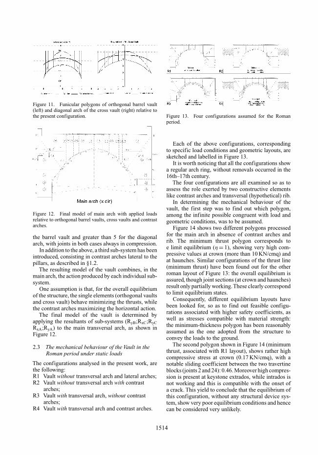
Figure 11. Funicular polygons of orthogonal barrel vault(left) and diagonal arch of the cross vault (right) relative tothe present configuration.
Figure 12. Final model of main arch with applied loadsrelative to orthogonal barrel vaults, cross vaults and contrastarches.
the barrel vault and greater than 5 for the diagonalarch, with joints in both cases always in compression.
In addition to the above, a third sub-system has beenintroduced, consisting in contrast arches lateral to thepillars, as described in §1.2.
The resulting model of the vault combines, in themain arch, the action produced by each individual sub-system.
One assumption is that, for the overall equilibriumof the structure, the single elements (orthogonal vaultsand cross vault) behave minimizing the thrusts, whilethe contrast arches maximizing the horizontal action.
The final model of the vault is determined byapplying the resultants of sub-systems (RyB;RxC;RyCRxA;RyA) to the main transversal arch, as shown inFigure 12.
2.3 The mechanical behaviour of the Vault in theRoman period under static loads
The configurations analysed in the present work, arethe following:R1 Vault without transversal arch and lateral arches;R2 Vault without transversal arch with contrast
arches;R3 Vault with transversal arch, without contrast
arches;R4 Vault with transversal arch and contrast arches.
Figure 13. Four configurations assumed for the Romanperiod.
Each of the above configurations, correspondingto specific load conditions and geometric layouts, aresketched and labelled in Figure 13.
It is worth noticing that all the configurations showa regular arch ring, without removals occurred in the16th–17th century.
The four configurations are all examined so as toassess the role exerted by two constructive elementslike contrast arches and transversal (hypothetical) rib.
In determining the mechanical behaviour of thevault, the first step was to find out which polygon,among the infinite possible congruent with load andgeometric conditions, was to be assumed.
Figure 14 shows two different polygons processedfor the main arch in absence of contrast arches andrib. The minimum thrust polygon corresponds toe limit equilibrium (η = 1), showing very high com-pressive values at crown (more than 10 KN/cmq) andat haunches. Similar configurations of the thrust line(minimum thrust) have been found out for the otherroman layout of Figure 13: the overall equilibrium isassured, though joint sections (at crown and haunches)result only partially working.These clearly correspondto limit equilibrium states.
Consequently, different equilibrium layouts havebeen looked for, so as to find out feasible configu-rations associated with higher safety coefficients, aswell as stresses compatible with material strength:the minimum-thickness polygon has been reasonablyassumed as the one adopted from the structure toconvey the loads to the ground.
The second polygon shown in Figure 14 (minimumthrust, associated with R1 layout), shows rather highcompressive stress at crown (0.17 KN/cmq), with anotable sliding coefficient between the two travertineblocks (joints 2 and 24): 0.46. Moreover high compres-sion is present at keystone extrados, while intrados isnot working and this is compatible with the onset ofa crack. This yield to conclude that the equilibrium ofthis configuration, without any structural device sys-tem, show very poor equilibrium conditions and hencecan be considered very unlikely.
1514
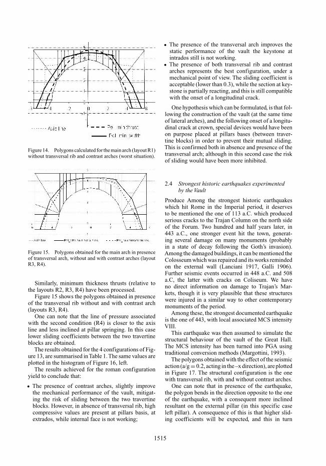
Figure 14. Polygons calculated for the main arch (layout R1)without transversal rib and contrast arches (worst situation).
Figure 15. Polygons obtained for the main arch in presenceof transversal arch, without and with contrast arches (layoutR3, R4).
Similarly, minimum thickness thrusts (relative tothe layouts R2, R3, R4) have been processed.
Figure 15 shows the polygons obtained in presenceof the transversal rib without and with contrast arch(layouts R3, R4).
One can note that the line of pressure associatedwith the second condition (R4) is closer to the axisline and less inclined at pillar springing. In this caselower sliding coefficients between the two travertineblocks are obtained.
The results obtained for the 4 configurations of Fig-ure 13, are summarised in Table 1. The same values areplotted in the histogram of Figure 16, left.
The results achieved for the roman configurationyield to conclude that:
• The presence of contrast arches, slightly improvethe mechanical performance of the vault, mitigat-ing the risk of sliding between the two travertineblocks. However, in absence of transversal rib, highcompressive values are present at pillars basis, atextrados, while internal face is not working;
• The presence of the transversal arch improves thestatic performance of the vault the keystone atintrados still is not working.
• The presence of both transversal rib and contrastarches represents the best configuration, under amechanical point of view. The sliding coefficient isacceptable (lower than 0.3), while the section at key-stone is partially reacting, and this is still compatiblewith the onset of a longitudinal crack.
One hypothesis which can be formulated, is that fol-lowing the construction of the vault (at the same timeof lateral arches), and the following onset of a longitu-dinal crack at crown, special devices would have beenon purpose placed at pillars bases (between traver-tine blocks) in order to prevent their mutual sliding.This is confirmed both in absence and presence of thetransversal arch; although in this second case the riskof sliding would have been more inhibited.
2.4 Strongest historic earthquakes experimentedby the Vault
Produce Among the strongest historic earthquakeswhich hit Rome in the Imperial period, it deservesto be mentioned the one of 113 a.C. which producedserious cracks to the Trajan Column on the north sideof the Forum. Two hundred and half years later, in443 a.C., one stronger event hit the town, generat-ing several damage on many monuments (probablyin a state of decay following the Goth’s invasion).Among the damaged buildings, it can be mentioned theColosseum which was repaired and its works remindedon the external wall (Lanciani 1917, Galli 1906).Further seismic events occurred in 448 a.C. and 508a.C, the latter with cracks on Coliseum. We haveno direct information on damage to Trajan’s Mar-kets, though it is very plausible that these structureswere injured in a similar way to other contemporarymonuments of the period.
Among these, the strongest documented earthquakeis the one of 443, with local associated MCS intensityVIII.
This earthquake was then assumed to simulate thestructural behaviour of the vault of the Great Hall.The MCS intensity has been turned into PGA usingtraditional conversion methods (Margottini, 1993).
The polygons obtained with the effect of the seismicaction (a/g = 0.2, acting in the –x direction), are plottedin Figure 17. The structural configuration is the onewith transversal rib, with and without contrast arches.
One can note that in presence of the earthquake,the polygon bends in the direction opposite to the oneof the earthquake, with a consequent more inclinedresultant on the external pillar (in this specific caseleft pillar). A consequence of this is that higher slid-ing coefficients will be expected, and this in turn
1515

Table 1. Results obtained for the 4 Roman configurations.
Roman arch
MaxHinges position Sliding compression Parzialized(ξ) η coefficient (KN/cmq) joints
R1 without transversal arch; 0,8;0.8;0.8 1,62 0,45 0,17 all upperwithout lateral arches part
R2 without transversal arch; 0.65; 0.55; 0.65 1,88 0,35 0,10 severalwith lateral arches joints
R3 with transversal arch; 0,73;0.7;0.73 2,16 0,40 0,09 crownwithout lateral arches
R4 with transversal arch; 0,6;0.67;06 2,72 0,29 0,06 crownwithout lateral arches
Figure 16. Left: histogram of h, sliding coefficient andcompressive stresses obtained for the 4 different configu-rations of the roman vault. Right: Histogram comparing thesafety coefficients obtained for the 4 configuration of thevault, under static and seismic loads.
Figure 17. Polygons obtained in presence of transversalrib, without and with contrast arches, with seismic actiona/g = −0.2.
determines higher risk of sliding between travertineblocks.
The results obtained in presence of earthquake, forthe 4 different configurations examined under staticloads, are shown inTable 2. Figure 16 (right) compares
the safety coefficients obtained for the 4 layouts of thevault under static and seismic loads.
Similarly to the static case, one can note that pass-ing from the former to the latter configuration, thesafety coefficients (η) of the vault tends to increase.However the first configuration is very close to alimit equilibrium (η = 1.09). Conversely, when thetwo structural elements are both present, the safetycoefficient becomes equal to 2.
The sliding coefficients show in all cases valuesconsiderably high, particularly in layouts 1 and 3 (0.59and 0.52 respectively). This yields to conclude thatthe earthquake severity experimented in 443 a.C.,might have onset an initial sliding mechanism betweentravertine blocks. In addition to this the joints betweenthese blocks are only partially working in compression.The eccentricities varies from (0.58 m of the first caseto 0.51 m of the last), so that a pillar portion, facing theinternal side of the vault, is not working. This mighthave produced the vertical cracks cutting the blocks(which can be observed still now) and the consequentcollapse of the travertine corbels.
3 CONCLUSIONS
The results achieved help to focus some crucial pointof the vault in its original configuration, as well as toformulate some hypothesis.
• The presence of contrast arches improves thebehaviour of the vault both under static and seis-mic loads. However their contribution in this caseis more relevant.
• Similarly, the transversal arch, if really conceived inthe original layout of the vault, helps the mechanicalperformance of the structure.
• The presence of anti-sliding devices on purposeplaced between the travertine blocks might have two
1516

Table 2. Results obtained for the 4 Roman configurations under the effect of a seismic action.
MaxHinges position Sliding compression Parzialized(ξ) η coefficient (KN/cmq) joints
Rs1 without transversal arch; 0,9;0,4;0,4 1,09 0,59 0,36 hauncheswithout lateral arches and pillar
basesRs2 without transversal arch; 0,8;0,27;0,4 1,56 0,47 0,19 haunches
with lateral arches and pillarbases
Rs3 with transversal arch; 0,79;0,5;0,32 1,63 0,52 0,12 hauncheswithout lateral arches and pillar
basesRs4 with transversal arch; 0,75;0,36;0,4 2,00 0,44 0,11 haunches
without lateral arches and pillarbases
order of purposes: they might have been placed fol-lowing the construction, once the longitudinal crackat crown became visible, in order to prevent thesliding mechanism. Conversely, following a seismicevent (more likely the one of 443 a.C.) once somevery small displacement between travertine blockscame to the light.
• The action of the earthquake was the possible causeproducing the (still visible) vertical cracks, cuttingthe travertine corbels.
The works realised in the structures in the last 20years, particularly those of 1996, have completelychanged the mechanical behaviour of the structure.In particular, the insertion of metallic bars, within theconcrete core of pillars as well as between travertineblocks, has definitively impeded any sliding likeli-hood, with the drawback of having locally modifiedthe masonry stiffness, and its possibility of adjustmentto external solicitations.
Further analysis of the vault taking in exam the alter-ations to the structure following the roman period areat present in progress, in order to compare the differentsafety margins from its construction until today.
REFERENCES
Boschi E., Guidoboni E., Ferrari G., Valensise G., GasperiniP. 1997. Catalogo dei forti terremoti storici in Italia dal461a.C al 1990. vol.2. (ING-SGA). Bologna, Italy. p.644.
Bianchini M. 1991. I Mercati di Traiano. In Bollettino diArcheologia del Ministero dei Beni Culturali e Ambientali(8) Marzo-Aprile 1991:102–121.
Bianchini M., Vitti M. 2003. Il Complesso dei Mercati diTraiano alla luce dei recenti restauri e delle indagini arche-ologiche. La fronte della Grande Aula e il suo sistemascalare. In Bullettino della Commissione ArcheologicaComunale di Roma (CIV), 2003: 285–306.
Ceradini V., Speranza E., Sgherri L., La Statica delle Volte,1997. In: Codice di Pratica per la conservazione deisassi di Matera, edited byA.Giuffrè, C.Carocci, La BauttaEditions, Bari.
Croci G., Viskovic A., Bozzetti A., Ungaro L., Vitti M. 2008.The Trajan Markets and their Great Hall – The Conser-vation Problems and the Structural Intervention for theImprovement of the Seismic Safety. In SAHC .
Galli I. 1906. I Terremoti nel Lazio. In: Stab. Tip. “PioStracca” (eds), Velletri.
Giavarini et. Al. 2005. La Basilica di Massenzio. Il mon-umento, i materiali, la stabilità, C. Giavarini (ed.),Roma.
Giovannoni G. 1913. Prototipi di archi rampanti incostruzioni romane. In Annali della Soc.Ingegneria edArchitettura italiana. N.10.
Heyman J. 1982. The masonry arch., Ellis Horwood, Chirch-ester.
Lancaster L. 2000. Building Trajan’s Markets 2: the Costruc-tion Process. In American Journal of Archaeology (104,4)2000: 755–785.
Lanciani R. 1917. Segni dei Terremoti negli edifizi di Romaantica. In Bullettino della Commissione ArcheologicaComunale, Rome.
Margottini C., Molin D., Serva L. 1993. Earthquake intensityvs peak ground acceleration in Italy (unpublished ms).
Mery E. Sur l’equilibre des voutes en berceau. InAnnales desPontes et Chausses, 1840.
Ricci C. 1929. Il Mercato di Traiano. RomaUngaro L., Vitti M. 2001. Sulle pavimentazioni dei Mercati
di Traiano. In Atti del’VIII Colloquio dell’AssociazioneItaliana per lo Studio e la Conservazione del Mosaico(21–23 febbraio 2001) F. Guidobaldi & A. Paribeni (eds),Ravenna: 393–414.
Ungaro L, Vitti M. 2007. I Mercati di Traiano affrontano ilnuovo millennio. Forma Urbis (XII, n. 2) febbraio 2007:4–15.
Vitti M. 2007. The Sequence of Buildings. In L. Ungaro (ed),The Museum of the Imperial Forums in Trajan’s Market,Milan: 53–59.
1517