the future of motion centric machine automation€¦ · the future of motion centric machine...
TRANSCRIPT

The future of motion centricmachine automation
PacDrive 3Faster time to market for your machinery
2
automationsolutions with PacDrive 3

3
Complete Solutions from Schneider Electric .....................................................Page 04Complete Solutions with PacDrive 3 .........................................................................Page 06Groundbreaking Systems Engineering ...................................................................Page 08PacDrive in Action ................................................................................................................Page 12Energy Savings ......................................................................................................................Page 16Technology ..............................................................................................................................Page 18Application Software ..........................................................................................................Page 20Tools ............................................................................................................................................Page 24Electronic Help Documentation ..................................................................................Page 38Controls .....................................................................................................................................Page 40Functional Safety .................................................................................................................Page 44I/O Communication ............................................................................................................Page 46Servo Drives, Multiaxis solutions..................................................................................Page 48Integrated Servo Drives ....................................................................................................Page 52Servo Drives, Stand-alone solutions .........................................................................Page 54Servo Motors ..........................................................................................................................Page 56 Robotics Solutions ..............................................................................................................Page 60HMI ...............................................................................................................................................Page 66Field Bus Devices .................................................................................................................Page 68Electrical Components .....................................................................................................Page 72PacDrive 3 and the Competition ................................................................................Page 74
Table of Contents:

4
System SoftwareSystem SoftwareSystem Software
System Software System SoftwareSystem Software
System Software
Remote IO
sercos
Complete Solutions from Schneider Electric
A global partner for the entire factorySchneider Electric is one of the world’s few globally active companies offering a full range of products and solutions for energy distribution and management, building automation and installations, and industrial automation. More than 100,000 employees in over 100 countries, 207 production facilities worldwide, and more than 16,000 sales offices form the backbone of a comprehensive network that can provide expert assistance on-site and on everything related to automation, factory equipment, and plant engineering.
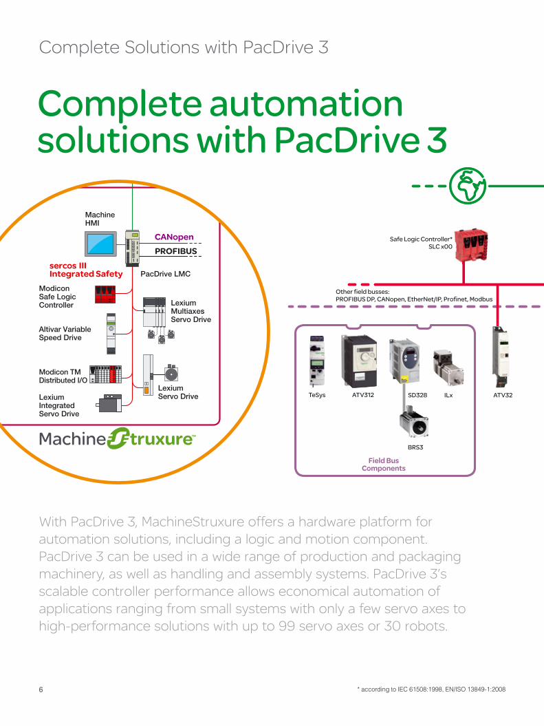
Fully integrated portfolio of solutions:PlantStruxure and MachineStruxure allow the scalable automation of processing systems, individual production machines, and entire production lines;PacDrive 3 (within circle) is the logic motion control solution for MachineStruxure

5
HMI controllers> Compact
Motion controllers> Performance
Drive controllers> Efficient
With its PlantStruxure and MachineStruxure auto-mation architectures, Schneider Electric has con-solidated its comprehensive product portfolio for industrial automation into a single, fully integrated solution. Everything originates from a single source and works together smoothly: Scalable control technology forms the foundation for fl exible auto-mation of both individual machines and processing systems. This solution is supplemented by a wide range of electrical equipment, featuring products that enhance individual solutions at different levels, from an entire factory to a single production line or an individual machine.
Schneider Electric also supplies solutions for the vertical integration of production processes: SCADA and MES solutions by Schneider Electric create a seamless connection between production fl oor and management systems. As a powerful, PC-based control and monitoring system, the
scalable Vijeo Citect SCADA software is suitable for a wide range of needs, from small companies to large corporations with highly complex processes and demanding availability requirements. Additional software systems enhance the range of solutions available for processes at different levels of the factory.
Schneider Electric offers a number of products and solutions for power distribution and conversion, for both primary and secondary distribution, including wiring and cabling technology and switchgear technology for supplying electrical power to ma-chines and production systems. Schneider Electric also focuses its efforts in the areas of energy management and metering technology, and has its own subsidiary for building automation and safety technology.
Complete Solutions from Schneider Electric >>
Different controllers, one software:SoMachine is your engineering workbench for Flexible Machine Control
The goal of shortening development times in machinery and plant engineering was the driving force behind the creation of Flexible Machine Control. The term Flexible Machine Control refers to a concept that consolidates the various mutually supplementing control plat-forms in MachineStruxure under the umbrella of a single software solution. The entire range of controllers, from simple drive-based control-
lers to high-performance motion controllers, can be programmed and put into operation with a single engineering workbench. This concept re-quires no new tools or training: It allows users to perform engineering tasks in the same familiar, comfortable software environment, regardless of the respective control platform. Comprehensive software libraries with tested Application Func-tion Blocks provide the needed support.
Flexible Machine Control
Logic controllers> Flexibility
sercos
6
Safe Logic Controller*SLC x00
Other field busses:PROFIBUS DP, CANopen, EtherNet/IP, Profinet, Modbus
Field BusComponents
BRS3
ILx ATV32TeSys ATV312 SD328
With PacDrive 3, MachineStruxure offers a hardware platform for automation solutions, including a logic and motion component. PacDrive 3 can be used in a wide range of production and packaging machinery, as well as handling and assembly systems. PacDrive 3’s scalable controller performance allows economical automation of applications ranging from small systems with only a few servo axes to high-performance solutions with up to 99 servo axes or 30 robots.
Complete Solutions with PacDrive 3
* according to IEC 61508:1998, EN/ISO 13849-1:2008
Complete automation solutions with PacDrive 3
SH
7
Ethernet, TCP/IP, OPC, FTP, HTTP, SMS, SMTP
Magelis HMI
LMC 101C, 201C, 300C, 400C, 600CLogic Motion Controllers
IT/COM
Logic Motion
LXM 62 Multiaxes Servo Drives + Power Supply + ILM 62 CM
ILM 62SH Torque Motor
LinearMotor
Ethernet, TCP/IP, OPC, FTP, HTTP, SMS, SMTP
sercos III + Integrated Safety*
SoMachineMotion
Motion
IT/COMIT/COM
Logic Motion
TM7Remote I/O
TM7Remote I/O
TM5 I/O
Distribution Box
Mechatronic Components
MAX R
P4
D2
SH
Stand-aloneServo Drives
LXM 52
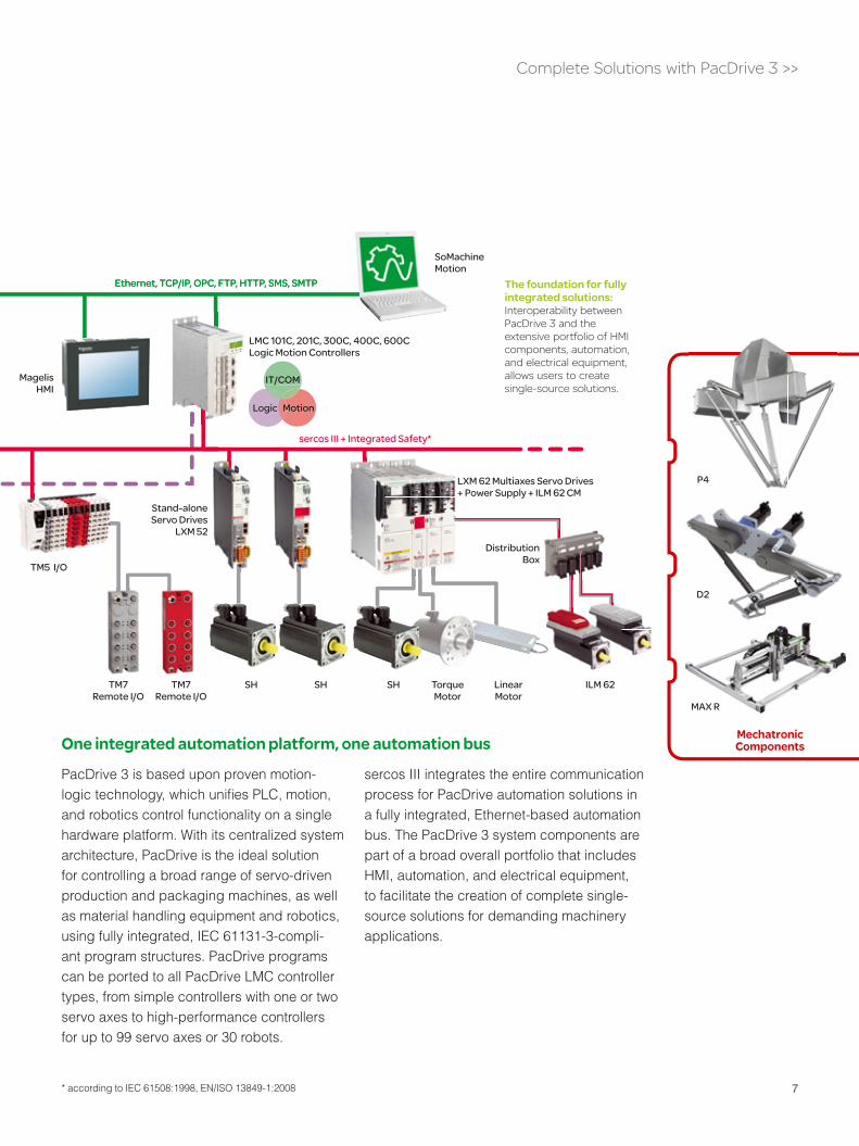
PacDrive 3 is based upon proven motion-logic technology, which unifi es PLC, motion, and robotics control functionality on a single hardware platform. With its centralized system architecture, PacDrive is the ideal solution for controlling a broad range of servo-driven production and packaging machines, as well as material handling equipment and robotics, using fully integrated, IEC 61131-3-compli-ant program structures. PacDrive programs can be ported to all PacDrive LMC controller types, from simple controllers with one or two servo axes to high-performance controllers for up to 99 servo axes or 30 robots.
sercos III integrates the entire communication process for PacDrive automation solutions in a fully integrated, Ethernet-based automation bus. The PacDrive 3 system components are part of a broad overall portfolio that includes HMI, automation, and electrical equipment, to facilitate the creation of complete single-source solutions for demanding machinery applications.
Complete Solutions with PacDrive 3 >>
The foundation for fully integrated solutions:Interoperability between PacDrive 3 and the extensive portfolio of HMI components, automation, and electrical equipment, allows users to create single-source solutions.
* according to IEC 61508:1998, EN/ISO 13849-1:2008
One integrated automation platform, one automation bus

8
The basis for sustainable automation solutionsFor years, PacDrive has pursued a technological approach designed to consistently reduce hardware and software complexity. Our consistent objective has been to hold the line against rising engineering costs for design, installation, and commissioning. PacDrive 3 opens up new possibilities for achieving this goal, and also introduces new technological approaches for long-term viability.
Groundbreaking Systems Engineering

9
Groundbreaking Systems Engineering >>
Better performance with increased scalability
Fully integrated Ethernet-based communication
PacDrive 3 provides a wide range of scal-able performance for synchronized multiaxis motion, PLC functionality, and robotic control on a single hardware platform, for both highly complex and simple machine confi gurations. Performance in the upper end of the range is suffi cient for up to 99 servo axes or 30 robots. At the lower end of the performance range, new controllers for a maximum of 4 or 8 servo axes are designed for more economical au-tomation of simple machines. This approach delivers fully integrated control technology for both simple and highly complex applications!
With the addition of sercos III, Schneider Elec-tric has created the fi rst fully Ethernet-based communication solution for PacDrive applica-tions, enabling communication with both drives and fi eld devices. sercos III also smoothes the way for the integration of safety automation*. sercos III is a true standard, it does not rely upon a specifi c manufacturer, and it is one of the most powerful Ethernet-based communica-tion solutions currently on the market.
* according to IEC 61508:1998, EN/ISO 13849-1:2008

10
Groundbreaking Systems Engineering >>
Flexible Drive Design
An innovative drive design allowsfl exible drive architectures: A multiaxis system, in which single and dual-axis servo drives are connected to a shared power supply, reduces costs and space require-ments in systems with more than four servo axes. Pluggable interconnects and a
quick-connect front-side bus also reduce installation costs.
For compact applications with a small number of servo axes, the newly developed stand-alone servo drives offer a more cost-effi cient approach to automation.

11
The latest programming standards
EPAS, SoMachine Motion’s central software development tool, is based upon CoDeSys V3 and offers the groundbreaking potential of object-oriented programming.
Groundbreaking Systems Engineering >>
One engineering tool, one project
SoMachine Motion is the new software devel-opment environment for the entire engineering process, including commissioning of PacDrive 3 and diagnostics. SoMachine Motion includes tools for motion design and drivetrain design (ECAM), program development (EPAS with ETEST, Vijeo Designer), diagnostics, and data handling (assistants) in a single package. A Safety Editor has also been integrated into SoMachine Motion for safety automation* software development. EDESIGN is the center-piece for a new type of graphic structuring of machine functions to further simplify software engineering.
* according to IEC 61508:1998, EN/ISO 13849-1:2008
12
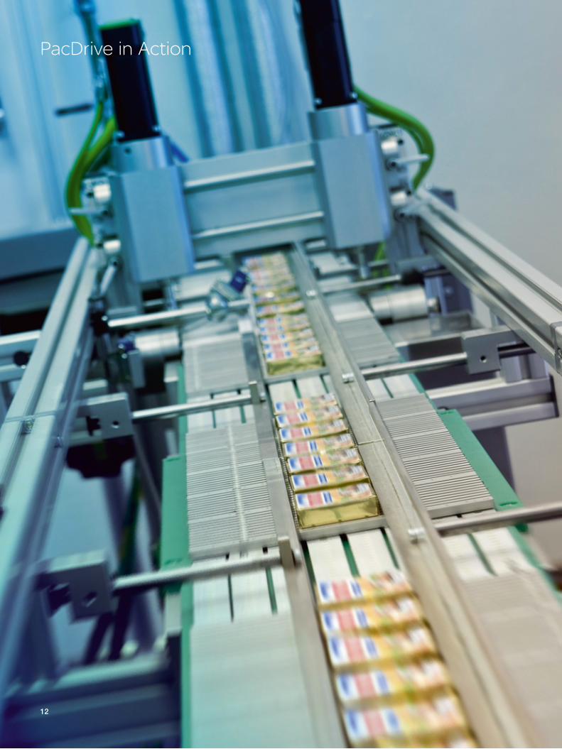
PacDrive in Action

13
READY
Proven technology
Compliance with OMAC and Weihenstephan Standard
PacDrive is a tested technology based upon internationally accepted open IT standards that conform with IEC, and has demonstrated its capabilities extensively since its introduction in 1998. More than 55.000 machines worldwide have already been automated with PacDrive! Schneider Electric is also a familiar name around the world, with a reputation for long-term reliability.
For international manufacturers of consumer goods products, the OMAC User Group’s PackML state machine plays an important role in integrating production and packaging machinery for production lines. The creators of PacDrive were active participants in OMAC from the very beginning, and integrated the
OMAC guidelines into PacDrive. The Weihen-stephan standard is also becoming increasingly important in the beverage industry, making production data available to management systems. PacDrive provides software Function Blocks for implementing this standard.
PacDrive in Action >>
International AcceptanceIn the consumer goods, durable goods, and capital goods industries, the machine buyers are the primary decision-makers when it comes to the automation systems for their production and packaging machinery. PacDrive has an excellent reputation among many European and international companies – for good reasons.

14
PacDrive in Action >>
At a glance: LEDs and system messages displayed in plaintext often provide crucial information about error locations.
High availability thanks to effective diagnostic tools
Plug-and-play technology for fast component replacement
Equipment availability depends to a large extent on how quickly operators can localize malfunctions and eliminate errors. PacDrive controllers provide basic diagnostic information in plaintext on the integrated display. A free diagnostic tool is also available for PacDrive users, both machine build-ers and operators. Any improper operation can
be traced, regardless of the individual machine‘s diagnostic capabilities. The diagnostic tool contains almost the same functionalities as the programming and commissioning tool for engineering, without the risk of unintended changes to the machine program.
The ability to easily replace the electronic components responsible for improper opera-tion is just as important as a rapid diagnosis of the improper operation itself. PacDrive users can quickly change out servo drives or servo motors with plug-and-play technology. Param-eterization of the replacement components via laptop or software installation is unnecessary. The centralized PacDrive controller detects the replacement components or motors by their electronic name plates, and confi gures them automatically. There is also no need to activate switches for the sercos or IP address. The con-troller performs a fi rmware check and updateswhen the equipment is replaced.
Simple servo drive configuration: Less mechanical effort, no parameterization – the centralized controller automatically configures servo drive and motors by using their electronic name plates

15
PacDrive in Action >>
Standards instead of proprietary control technology: IEC 61131-3-compliant programming languages are familiar to technical personnel, thus reducing the need for time-con-suming training sessions in proprietary programming solutions
Faster training thanks to standardized programming
Remote maintenance options
Consumer goods manufacturers are very enthusiastic about the fully integrated IEC 61131-3-compliant program structure in machines automated with PacDrive. These companies generally have personnel who are familiar with IEC programming, and can handle retooling of lines or machine adjustments internally. The proprietary, manufacturer-specifi c programming con-cepts so common in robot-assisted machine
designs, on the other hand, demand intensive training.A training program for PacDrive 3 is avail-able, as well as a migration seminar for the changeover from PacDrive M to PacDrive 3. The new PacDrive 3 training program will include training modules on programming, commissioning, and service, as well as me-chatronic design and robotics.
Remote maintenance reduces travel costs and increases availability by accelerating response times. PacDrive provides the interfaces and/or protocols needed for remote maintenance via
the Internet, modem, and mobile telephony. Schneider Electric provides advice and support to machine users and machine builders for inte-gration of the most practical options – worldwide.

16
Energy Savings
Energy efficiency – the selling point with a future! The consumer goods industry places a high premium on energy-efficient manufacturing systems: Lower energy use reduces machinery lifecycle costs, ashigher energy prices are becoming an increasinglyimportant factor. Another factor not to be underestimated in the competition for market share, particularly in the consumer sector, is to be seen as a “green“ company. Environmental consciousness is increasingly important to consumers. Develop an energy-efficient production and packaging system, and you too can benefit from a greener image – Schneider Electric makes it easy for you with PacDrive.

17
Energy Savings >>
Efficient motor technology
DC bus sharing and energy recovery
Automation without control cabinets
Energy-optimized motion design
Save energy with the “intelligent line shaft“
Servo technology is one of the most effi cient ways of transforming electrical energy intokinetic energy. Among industrial electrical motors, the high effi ciency of servo motorsmakes statutory minimum effi ciency levels su-perfl uous. This is particularly true for PacDrive servo motors: Whether you are using standard servos or servos with an integrated servo drive, all of our motors deliver high effi ciency and low inertial loads.
DC bus sharing among servo drives is astandard feature for PacDrive 3 LXM 62. Thanks to the front-side quick-connect no additional installation effort is required to connect to the bus. DC bus sharing is particularly well suited for packaging machines with servo drives that do not all need power at the same time. The generous storage capacity in these servo drives and their power supplies optimizes the use of the energy produced during a process.
Like other electronic components, servo drives in the control cabinet generate heat. If theresulting heat exceeds permissible levels, then the control cabinet needs to be cooled. Energy is used to dissipate energy! ILM servo motors with integrated drive electronics, on the other hand, require only a shared power supply in the control cabinet. This lowers heat in the control cabinet and reduces the need for climate control.
Just as in skiing, technically optimized motion sequences require less power, put less stresson joints, and can be executed with less energy. Good tools create the basis for energy-optimized motion design, which reduces the need for braking energy. These tools offer various motion rules for simulating different approaches. Or they can use blending functions to create ideal pick-and-place paths for robots. PacDrive-Tools can do it!
When machine speeds increase, some indi-vidual axis movements exceed their set energy consumption limits. This circumstance can’t be changed if the system uses an electronic line shaft that rigidly synchronizes all of the axes with the master. The alternative “intelligent line shaft,” however, offers a new approach: Here the vir-tual master can activate a speed profi le over the course of a machine cycle, increasing speed only for portions of the motion profi le that do not involve critical changes in energy consumption. The speed of the critical individual axis movements, however, is increased only up to a predefi ned limit.

18
Logic motion control – the basis for standardized solutions For more than a decade, a central element in PacDrive has been the integration of motion, PLC, and IT functionalities in an automation platform. This allows the creation of fully integrated software structures that enable modular machine designs and help to reduce engineering times.
Centralized controllers for all machine functions
PacDrive’s digital system architecture is based upon the concept of a centralized controller. Using an IEC 61131-3-compliant machine program, a single processor performs all control functions, from Cartesian and robotic motion to temperature regulation and machine logic. All of the system functions run through the centralized controller, from the human-machine interface to motion and device bus communication, line synchronization, and vertical integration.
Basis for simulation and plug-and-play
The centralized controller generates the motion data for all servo axes in the system. It also centrally stores relevant system data and equipment-specifi c parameters. This centralized approach offers signifi cant ben-efi ts: Moves can be tested and simulated in the controller without having to connect real drives. The controller supports reliable communication with every servo axis,including process data and motor status, which can be analyzed for different purposes. Servo motors and drives can also be automatically confi gured based upon electronic ‘name plates.’ The controller recognizes the motors and drives, and can send the centrally stored parameters to each device for easy commissioning or replacement. Confi guration of individual drives is a thing of the past.
Technology

19
Scalable – from basic to high performanceRegardless of whether a system involves one machine or an entire production line, a single controller can control up to 99 servo axes or up to 30 robots. Even less complex architectures can be automated economically: The scal-able controller hardware also offers a solution for applications with 4 or 8 axes. It can even be used as a pure-play PLC or a data con-centrator to acquire production data from a packaging line. Users can synchronize up to 40 controllers in real time – a fully integrated solution for entire production lines.
A foundation for fully integrated software designsOne of the major advantages of centralized controller designs is a unifi ed software development environment, with one program-ming tool to implement the functionalities. There is no need for additional tools, some of which might be proprietary. One tool, one programming standard, one software structure: This is the key to the groundbreaking approach of modular engineering, in which mechatronic functions are mapped on reusable software modules. To counter the trend toward rising engineering hours, pretested software libraries minimize programming time and ease the way for FDA validation based upon cGMP/GAMP and CFR 21 Part 11.
Technology >>
sercos automation bus
IT
MotionPLC
Motorcontrol
loops
Motorcontrol
loops
Motorcontrol
loops
Setpoint positionControl info
Service data
Centralized machine controller
Distributedservo drives
Current position Status info Service Data
ERP Data
Real-time line synchronization
991 2
Ethernet

20
Application Software
The hardware design has to be correct, of course, but it‘s the software that really makes a solution work! Companies often spend a great deal more on software than on hardware, and this trend is on the rise. The PacDrive software concept provides a clear response to this development: Machine functions that have been mapped in standardized software modules and collected in software libraries serve as tested, off-the-shelf software to shorten development times and increase engineering quality. A universal program structure also paves the way for modular, reusable machine programs.
Solutions to counter rising engineering costs

21
advanced
EM(Equipment module)
AFB
System Functions
= AFB + Op-Mode + Diagn. + Error handling
(Application Function Block)
conventional
User program
AFB
System Functions
(Application Function Block)
User program
PacDriveProgram Structure
Conventional Programming Advanced Programming
Application Software >>
PacDrive portion of the pre-programmed application
User portion of thepre-programmed application
The PacDrive software concept offers two ways to counter rising engineering costs: Programs can be programmed either in the conventional way, using Application Function Blocks (AFBs), or by using PacDrive’s predefi ned program structure and Equipment Modules (EMs): The latter option further reduces programming work for the user. The program structure also creates standardized modular software to improve the reusability of machine modules.
Two possible paths to a single destination
Significant reduction in programming times Higher software quality
with documented and well-tested software Easier program
validation IEC 61131-3
compliant AFBs
Conventional programming with Function Blocks
PacDrive software libraries consist of Function Blocks (AFBs - Application Function Blocks), which map a variety of motion, PLC, visualization, and IT functionalities in pre-programmed software objects. These range from uni-versal AFBs for generating axis movements in positioning and movement functions to temperature regulation operations. The libraries also contain Function Blocks that can be parameterized for complete mechatronic functional units, such as robots, rolling and unrolling functions, fl ying shear, or fi lm sealing units.
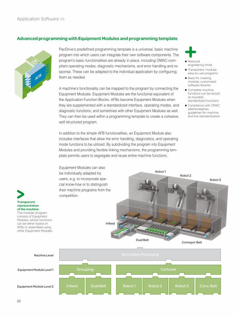
22
Infeed
Dual BeltConveyor Belt
Robot 1Robot 2
Robot 3
Infeed Dual Belt Robot 1 Robot 2 Robot 3 Conv. Belt
Grouping
Secondary Packaging
Cartoner
Machine Level
Equipment Module Level 1
Equipment Module Level 2
Reduced engineering times Transparent, modular,
easy-to-use programs Basis for creating
modular, customized software libraries Complete machine
functions can be stored as reusable, standardized functions Compliance with OMAC
Weihenstephan guidelines for machine and line standardization
Advanced programming with Equipment Modules and programming template
Application Software >>
PacDrive‘s predefi ned programming template is a universal, basic machine program into which users can integrate their own software components. The program’s basic functionalities are already in place, including OMAC-com-pliant operating modes, diagnostic mechanisms, and error handling and re-sponse. These can be adapted to the individual application by confi guringthem as needed.
A machine‘s functionality can be mapped to the program by connecting the Equipment Modules. Equipment Modules are the functional equivalent of the Application Function Blocks. AFBs become Equipment Modules when they are supplemented with a standardized interface, operating modes, and diagnostic functions, and sometimes with other Equipment Modules as well. They can then be used within a programming template to create a cohesive, well structured program.
In addition to the simple AFB functionalities, an Equipment Module also includes interfaces that allow the error handling, diagnostics, and operating mode functions to be utilized. By subdividing the program into Equipment Modules and providing fl exible linking mechanisms, the programming tem-plate permits users to segregate and reuse entire machine functions.
Equipment Modules can also be individually adapted by users, e.g. to incorporate spe-cial know-how or to distinguish their machine programs from the competition.
Transparent representation of the machine: The modular program consists of Equipment Modules, whose functions can be either based on AFBs or assembled using other Equipment Modules.

23
Identical functions available as AFBs or Equipment Modules
The software functions available for PacDrive have been created as AFBs pluscorresponding Equipment Modules.
The libraries contain most of the functionalities needed for forming, fi lling, and sealing machines, dosers, cartoners, labelers, pick-and-place applications, and end-of-line packaging machines. They also offer a variety of mechatronic functions typically used in production machinery and in handling, assembly, and sorting systems.
The AFBs and EMs are documented and have been well-tested in practical use, a basic requirement for high software quality, short engineering times, and rapid commissioning. This also makes certifi -cation of machines and software much easier.
Application Software >>
An overview of the most important PacDrive libraries, with examples showing the scope of function. The software functions are available as either AFBs or Equip-ment Modules
Extensive Function Block libraries, including PLCopen Enhanced software
quality thanks to off- the-shelf software (FDA, cGMP, 21CFR Part 11)
Application Library Included Application Function Blocks (examples)
Individual machine PD_Template.Lib Function Blocks for operating mode management, control of state changes, exception handling, error reaction, or predefi ned commissioning screens
PLC Function Blocks PacDrive.Lib Standard PLC functions such as bit or conversion functions, shift register for LREAL values with access functions, etc.
FieldbusDevices.Lib Field bus diagnostic function blocks, Function Blocks for motor protection switches or frequency converter, etc.
System.Lib Event-driven adjustments of any number of cam switch groups
Motion Function Blocks PacDriveLibModules.Lib Universal axis AFB for homing, positioning, curve functionality, jogging, etc.
PacDrive.Lib Safety*/Hardware, e.g. Power on and power off of axes with monitoring functions, etc.
PacDrive.Lib Axis and encoder positions, homing, positioning (automatic and manual), virtual master axis control, minimization of mechanical wear and tear, increase of machine speed,
and reduction of energy usage with the ´Intelligent Line Shaft,́ etc.
Cam disk handling PacDrive.Lib Processing from table or modifi cation of cam disk profi les on the fl y, cold or warm start functions, etc.
Mathematical functions PacDrive.Lib Matrix operations, vector and polynomial functions or functions for toggle transformations, etc.
Technology functions PacDrive.Lib and others PID controller, registration mark control, winding and unwinding with and without dancer, sealing, etc.
Torque handling System.Lib Speed-dependent torque limit (e.g. for bottle sealing equipment), etc.
Robotics Robotic.Lib Automatic path planning, path generation and optimization, transformation to different kinematics, belt tracking, synchronization of robots, etc.
Infeed MultiBelt.lib/-Module.lib Control of dual-belt and multi-belt mechanisms for product grouping and infeed
Infeed SmartInfeed.lib/-Module.lib Control of serial conveyor belts as infeed lines, product detection, management, and transfer, synchronization of conveyor belts, etc..
Standardization ISA.Lib, Weihenstephan.Lib Weihenstephan Standard, OMAC PackML FDA
HMI application Vijeo Designer Vector graphics for design, open source software, functions for machine operation, including recipe handling, sample screens, simulation/teleservice,
also via Web servers, etc.
Machine Pilot programming SoMachine Motion Universally adaptable sample programming template
* according to IEC 61508:1998, EN/ISO 13849-1:2008

24
24
Tools
Actively shaping the modern engineering process Machinery is becoming increasingly complex, leading to similar growth in the quantity of software and data. To keep pace with this trend, engineers will have to rethink their project processes and adopt new approaches. SoMachine Motion is the engineering workbench for PacDrive 3 applications. With SoMachine Motion, you can help actively shape the current transfor-mation in engineering.

25
Tools >>
Engineering Workbench The SoMachine Motion workbench consoli-dates in a single package the tools needed for the entire lifecycle of a PacDrive 3 solution: Tools for program development, HMI applica-tions, motion design, drivetrain design, and data handling provide all of the functionalities needed for engineering and commissioning. Users can use the integrated help system when creating programs, and the workbench’s inte-grated documentation can answer questions about PacDrive 3 hardware components.
A powerful diagnostic tool permits rapid analy-sis of detected problems during production.
No need for folders full of CDs or optional tools: The necessary tools are available once SoMachine Motion is installed on the user‘s Windows PC. Selected individual tools can be installed for servicing or other purposes that require only part of the program‘s total function-ality. For example, installation can be limited to diagnostic functions for servicing purposes.
SoMachine Motion: A workbench with tools for all aspects of the engineering process and for service during live operation
Intuitive user interface:The tools are structured based upon area of use (upper left), and dedicated icons allow users to orient themselves easily within the program

26
Tools >>
One project, multiple participants: A central database and a powerful multiuser design will enable future users to have simultaneous access to software projects down to the Function Block level
Object-oriented programming: EPAS, the programming tool for SoMachine Motion, is based upon CoDeSys V3
Continuity preserves value
In addition to these new tools, SoMachine Mo-tion also includes the proven PacDrive M tools. Projects created for PacDrive M in EPAS-4 can be converted for editing in SoMachine Motion, and can be ported to PacDrive 3. The idea of confronting rising engineering costs by producing modular, reusable software con-tinues in the next generation of PacDrive.
Project conversion: Software projects created with EPAS-4 can be converted for SoMachine Motion
Open standards create trust
SoMachine Motion can be used to create IEC 61131-3-compliant programs. SoMachine Motion’s central software development tool is based upon CoDeSys V3, thus offering the op-tion of either traditional or object-oriented pro-gramming. Object-oriented programming has been the de facto standard in embedded and PC software development for years, and has also been a central focus of technical instruc-tion at universities.
Team A
Team (...) Team C
Team BProject data
Project file – central data pool
Multiuser design with a central databaseSoMachine Motion stores all project data in a central database (project fi le). These data are universally available for all of the tools in the workbench. This central storage of project data forms the basis for SoMachine Motion’s soon-to-be-released multiuser design: An entire
team can then work concurrently on the same software project, with simultaneous access to AFBs (Application Function Blocks) and motion profi les. This reduces unwieldy version manage-ment processes and coordination tasks that can unnecessarily slow down teamwork.
27
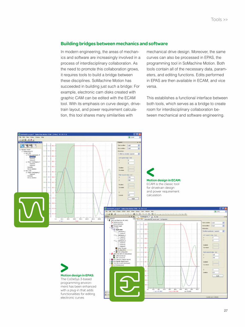
Building bridges between mechanics and softwareIn modern engineering, the areas of mechan-ics and software are increasingly involved in a process of interdisciplinary collaboration. As the need to promote this collaboration grows, it requires tools to build a bridge between these disciplines. SoMachine Motion has succeeded in building just such a bridge: For example, electronic cam disks created with graphic CAM can be edited with the ECAM tool. With its emphasis on curve design, drive-train layout, and power requirement calcula-tion, this tool shares many similarities with
mechanical drive design. Moreover, the same curves can also be processed in EPAS, the programming tool in SoMachine Motion. Both tools contain all of the necessary data, param-eters, and editing functions. Edits performed in EPAS are then available in ECAM, and vice versa.
This establishes a functional interface between both tools, which serves as a bridge to create room for interdisciplinary collaboration be-tween mechanical and software engineering.
Tools >>
Motion design in ECAM:ECAM is the classic tool for drivetrain design and power requirement calculation
Motion design in EPAS: The CoDeSys 3-based programming environ-ment has been enhanced with a plug-in that adds functionalities for editing electronic curves

28
With its combination of comprehensive functionality and proven software tools, theEPAS Automation Toolkit is a powerful programming tool for PacDrive applications.EPAS can be run from SoMachine Motion, and its interface has the look and feel of typicalWindows applications. Easy navigation between editors and within the libraries provides for ease of use and transparencywhen creating and simulating programs andcommissioning with EPAS.
EPAS functionality covers the engineering process: With the integrated confi guration editor, a few entries are suffi cient to confi gure, parame-terize, modify, or expand the solution’s hardware components and fi eld buses. EPAS’s customiz-able HMI offers assistance when developing, testing, and simulating the controller application. Preprogrammed screens are already avail-able for the commissioning process. Machine programs can be simulated onscreen in EPAS without real drives.
EPASUniform programming and parameterization
Trace Function: The integrated oscilloscope in EPAS permits simultaneous plotting and display of multiple PLC and motion signals, as well as mixed PLC and motion signals with millisecond resolution
Configuration editor: Hardware components and field buses (PROFIBUS DP, CANopen, sercos III, ...) can be configured and parameterized in the editor
Tools >>

29
Ladder Diagram
Instruction List
Structured Text
Continuous Function Chart
Function Block
Sequential Function Chart
Tools >>
System check of device configuration: The nodes in the sercos interface can be scanned, resulting in a display with status information on each node
An eight-channel software oscilloscope integrat-ed into EPAS permits simultaneous plotting of up to eight PLC and motion variables (including mixed variables). During commissioning, the tool’s message logger makes it easy to track down the source of system and user diagnosis messages.
EPAS can be used for all types of the PacDrive 3 controller. Conversion of projects from one controller type to another is unnecessary, which means that programs can be downloaded to different controllers.
Uniform programming and parameterization Program simulation
without real axes Hardware configuration
and parameterization without the need for additional editors Visualization tool with
preprogrammed commissioning and service screens Simultaneous trace
plotting of PLC and motion signals (software oscilloscope) Diagnostic functions,
including message logger IEC 61131-3 editors CoDeSys V3-based
Programming in compli-ance with IEC 61131-3: EPAS includes editors and debuggers for all six stan-dard IEC languages
30
Tools >>
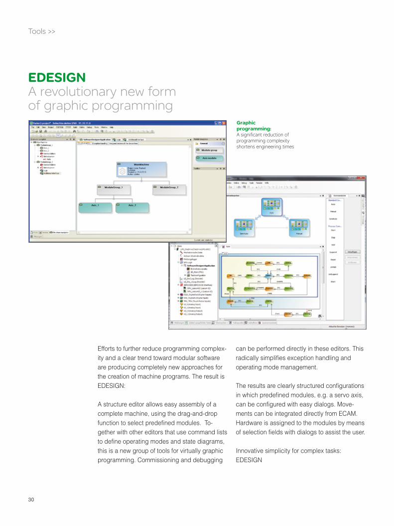
Efforts to further reduce programming complex-ity and a clear trend toward modular software are producing completely new approaches for the creation of machine programs. The result is EDESIGN:
A structure editor allows easy assembly of a complete machine, using the drag-and-drop function to select predefi ned modules. To-gether with other editors that use command lists to defi ne operating modes and state diagrams, this is a new group of tools for virtually graphic programming. Commissioning and debugging
can be performed directly in these editors. This radically simplifi es exception handling and operating mode management.
The results are clearly structured confi gurations in which predefi ned modules, e.g. a servo axis, can be confi gured with easy dialogs. Move-ments can be integrated directly from ECAM. Hardware is assigned to the modules by means of selection fi elds with dialogs to assist the user.
Innovative simplicity for complex tasks: EDESIGN
EDESIGNA revolutionary new form of graphic programming
Graphic programming:A significant reduction of programming complexity shortens engineering times

31
Tools >>
PacDrive 3 libraries have AFBs (Application Function Blocks) that can be parameterized for a variety of mechatronic, mathematical, and technical process functions. The ability to create programs based upon years of proven and documented off-the-shelf software not only saves time, but also signifi cantly improves software quality. SoMachine Motion ETESTtool can also be used to develop and execute
system tests of modular machine programs: By using test routines that automatically test isolated software modules within a program, software problems can be identifi ed even at an early phase of the project. Such module tests are increasingly recognized as a valuable contribution to software validation. SoMachine Motion uses ETEST for this valuable function.
ETESTQuality – A matter of design
Early detection of software problems: ETEST is the tool for creating and performing automated software tests

32
Tools >>
The integration of safety automation into stan-dard automation is one of the most important user requirements. PacDrive 3 is currently being prepared to meet these requirements. SoMachine Motion includes an editor for safety automation. Thus the creation of IEC 61131-3-compliant programs for PacDrive
safety controllers is as integral to the work-bench as the parameterization of system component safety functions. In addition to the program editor, the tool also has a confi gura-tion editor that can be used to parameterize components such as I/O components or servo drives that are integrated into the safety solution.
SoSafeSafety Editor* & Configurator for safe automation
IEC 61131-3-Editor: The programming lan-guages Function Block Diagram (FBD) and Ladder Diagram (LD) can be used to develop the program code
* according to IEC 61508:1998, EN/ISO 13849-1:2008

33
Tools >>
ECAM is a single tool that can be used to design a complete system, from mechanics and motion design to calculation of system power requirements. To streamline the engineering process, ECAM includes a library of predefi ned standard mechanical drive confi gurations, simplifi ed motion design with a graphical motion profi le editor, and standard motion profi les.
This makes ECAM a functional tool for me-chanical engineers in designing and selecting motors, gears, and power components. Tools for calculating power requirements and deter-mining the energy available from the DC bus also pave the way for energy-effi cient machine designs.
A seamless, bidirectional interface allows curve data and mechanical parameters to be automa-tically provided to EPAS. Data can be adapted in EPAS and are then immediately available again in ECAM – a bridge between mechanics and software.
Graphical motion design:By cascading editor windows, users can place movement patterns in chronological relationship to one another
Drivetrain design: Predefined applications offer adaptability for typical power transmission con-figurations
Motion design with virtual or real master axes Use of multisegment
profiles, such as VDI 2143 profiles or fifth order polynomials Import of cam tables via
Excel tables Database for servo
motor/drive and gear reduction sizing and selection Predefined applications
such as general loading condition, belt drive, spindle drive, rack-and-pinion drive, and crank drive
ECAMMotion and drivetrain design

34
Tools >>
Vijeo Designer can be used to confi gure all Magelis touchscreen panels, from the small-est 3.8“ panel up to complex HMI applications for the 19“ panels. The tool set also includes the ARTI protocol driver so that users can access runtime system variables via the browser. The tool’s graphical editor provides a number of ready-made elements for custom-izing HMI interfaces. In addition, a graphics library has more than 4,000 predefi ned vector
graphics. The integrated recipe maintenance program can manage 256 recipes with 1,024 ingredients in up to 32 recipe groups. Users can perform periodic or event-driven pro-cessing of Java-based procedures to auto-mate operations such as switching screens, performing mathematical and logical calcu-lations, and making automatic changes in variables. The alarm management system is designed for up to 9,999 alarms.
Open-source software included: A suggested schematic diagram is easy to modify, simplifies the learning process for Vijeo Designer, and produces fast results
One tool for all panels Predefined functions
and graphic elements provide design support Fast solutions with
open-source sample program ARTI driver for browsing
control variables without an OPC server
Vijeo DesignerCustomized design of HMI interfaces
Vijeo Designer:A large number of predefined elements, graphics libraries, recipe and alarm management functions, and an easy-to-modify suggested schematic make HMI development fast and easy.

35
Tools >>
The Controller Assistant stores data and fi les on the fl ash drive and creates a copy on the user’s PC. If necessary, this copy can be used to restore the program to its original status. The tool’s functions also include the creation of CompactFlash cards for PacDrive control-lers (including bootable cards). These cards include the VxWorks operating system and fi rmware.
The Controller Assistant supports fi rmware to be exchanged between PacDrive controllers via Ethernet. If a user wants to check a network for existing PacDrive controllers, the Controller Assistant can identify connected controllers and display their identifying data.
The Drives Assistant allows the maintenance and exchange of fi rmware on sercos nodes. Servo drives, bus interfaces, and even TM5 I/O modules can be easily supplied with new fi rmware from a central location. The integrated management of fi rmware versions optimizes their storage and retrieval.
Support tools make it easier for PacDrive users to handle program and fi rmware data and to per-form program version management.
Tools for data management
Controller AssistantDrives Assistant
Data management: Tools make it easier to transfer and handle program and firmware data. The screenshot shows the Controller Assistant

36
EPAS integrates comprehensive diagnostic functionalities. EPAS is not always available, however, if a machine breaks down during production. This is why PacDrive Diagnostics was developed specifi cally for use by ma-chine operators for servicing purposes. This tool offers a full range of diagnostic functions, runs independently of EPAS, and is available
at no cost to PacDrive users. It can be used without any programming knowledge, since the intuitive program interface allows users to quickly collect the necessary servicing data. Diagnostic information can be displayed upon demand, stored, or forwarded directly to techni-cal support. The tool can be used regardless of the fi rmware version.
Simple tool for collecting service-related system data No EPAS required Firmware-independent System map of servo
drive data (drives, message loggers, cam switch group, etc.) Intuitive user interface
Tools >>
DiagnosticsMaintenance without EPAS
System check: Diagnostics can be used to check the hardware and software versions of the servo drive components on the PC
Diagnosis of machine malfunctions: Diagnostics can be used to perform comprehensive system diagnostics even without programmingknowledge. The screenshot shows a check of the PLC configuration.

38
Electronic Help Documentation
Complete online documentation
Guided Tours – Help for beginners, including an interactive demo project Keyword search in the
documentation via the Index function Search for topics using
content directories Extensive
documentation of library functions
Even with intuitive tool interfaces, sometimes you need help, from your first steps with SoMachine Motion to routine project work. Experience has shown that support is most useful when it is available right on the screen. In SoMachine Motion, ´Guided Tours´ familiarize users with the tools, while electronic documentation on tool and library functions make printed manuals unnecessary.
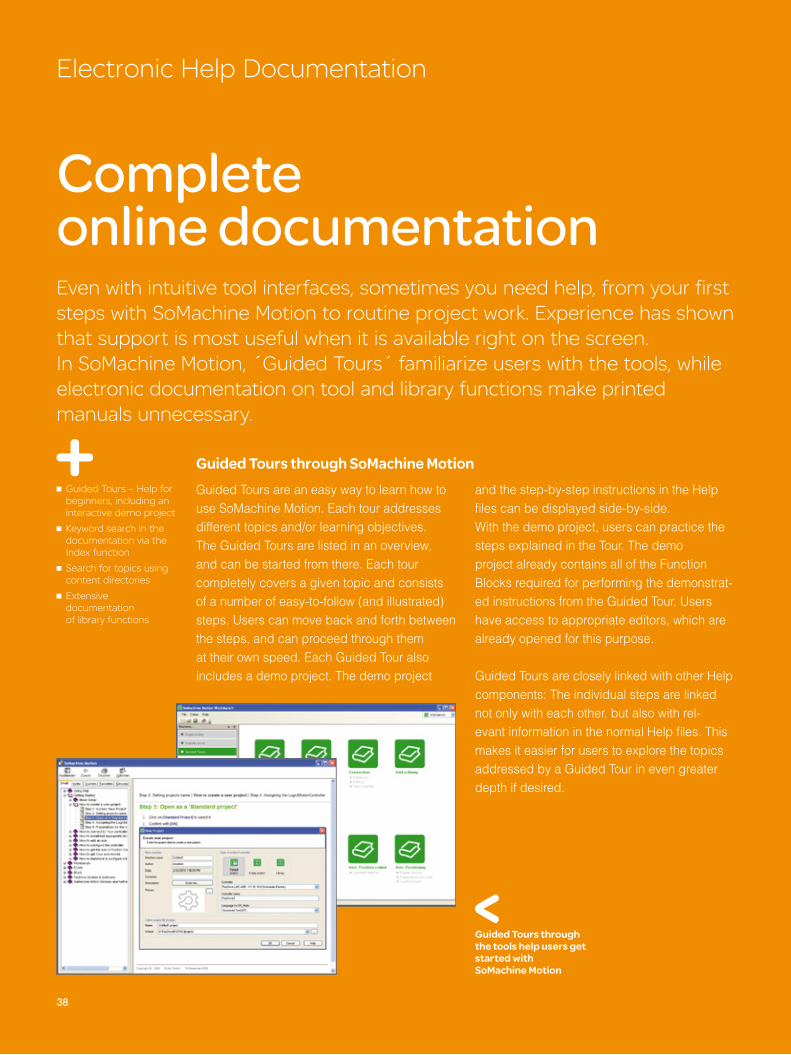
Guided Tours through SoMachine MotionGuided Tours are an easy way to learn how to use SoMachine Motion. Each tour addresses different topics and/or learning objectives. The Guided Tours are listed in an overview, and can be started from there. Each tour completely covers a given topic and consists of a number of easy-to-follow (and illustrated) steps. Users can move back and forth between the steps, and can proceed through themat their own speed. Each Guided Tour alsoincludes a demo project. The demo project
and the step-by-step instructions in the Help fi les can be displayed side-by-side. With the demo project, users can practice the steps explained in the Tour. The demo project already contains all of the Function Blocks required for performing the demonstrat-ed instructions from the Guided Tour. Users have access to appropriate editors, which are already opened for this purpose.
Guided Tours are closely linked with other Help components: The individual steps are linked not only with each other, but also with rel-evant information in the normal Help fi les. This makes it easier for users to explore the topics addressed by a Guided Tour in even greater depth if desired.
Guided Tours through the tools help users get started with SoMachine Motion

39
Electronic Help Documentation >>
Electronic Documentation – the paperless manual
The tools, particularly EPAS and ECAM, offer comprehensive documentation for users.This wide array of systematically recorded information, which can be accessed by keyword search, provides comprehensive technical background information and instructions on using the tool. The unlimited availability of the ‘E-Documentation’ makes it unnecessary to keep a hardcopy manual next to the keyboard.
The SoMachine Motion tools are largely intuitive in their operation. The Help function for each tool provides answers to more detailed questions on operation, or on the technical and mathematical background of the available functions. As with typical Windows applica-tions, the Help function can be started with the click of a mouse.
The EPAS E-Documentation offers two ways to access information: A table of contents lists the topics contained in the E-Documentation. Users can also use the Index to search alpha-betically for available topics. A search algo-rithm limits the content that is displayed.
On-screen documentation is also available for library Function Blocks. The technical back-ground, scope of functions, parameterization, and integration of each function are described in detail. Integrated hyperlinks in the explana-tions let users jump to other sections of the documentation for more detailed explanations of specifi c terms.
Search via the Index: The terms related to a particular topic are listed in alphabetical order; the input field for keywords is shown above the list
Documentation of library Function Blocks: The image shows the table of contents and one page from the library Function Block for implementing wrapping mechanisms with and without a dancer
Search in content directories:
Calling up help information in EPAS
40
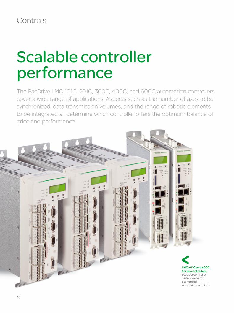
Scalable controller performance The PacDrive LMC 101C, 201C, 300C, 400C, and 600C automation controllers cover a wide range of applications. Aspects such as the number of axes to be synchronized, data transmission volumes, and the range of robotic elements to be integrated all determine which controller offers the optimum balance of price and performance.
Controls
LMC x01C und x00C Series controllers: Scalable controllerperformance for economical automation solutions.
41
A single platform for all controller functionalities
LMC x01C and x00C controllers provide scal-able performance for synchronizing up to 99 servo axes (at 1 msec network update rate for 99 axes), and for up to 255 virtual axes. In addition to motion functionality, all controllers combine an integrated PLC, HMI interfaces, and IT functionalities on a single hardware platform. They are software-compatible, since each of these controllers has identical Schneider Electric Logic Motion Runtime soft-ware. Users can program up to 4096 dynamic electronic cam disks operating in parallel. The program can switch between electronic cam disks during operation. Control can be distributed across a number of continuous, periodic, or event-driven user tasks.
Each controller has two integrated cam switch groups, each with 32 cam disks. The system can allocate up to 254 cams. Up to 32 different positioning or encoder signals can be as-signed to each of the two cam switch groups. Cam signals can be sent to a memory cell or to a digital output.
Depending upon the controller type, memory can be up to 512 MB DDR2 RAM, or 128 or 256 KB NV RAM, with additional compact Flash memory of 128 MB or more. The memory card can be changed out without removing the enclosure, as can the battery. An alphanumeric display shows diagnostic data. The controllers include an integrated eight-channel software oscilloscope and a message logger for diagnostics. All controller types are CE and cULus certifi ed.
A scalable controller platform One runtime software All controllers are
software-compatible Ethernet-based, fully
integrated automation bus Can control up to 99
real axes and another 255 virtual axes Up to 254 sercos III
nodes 1 msec network
update rate for 99 axes Up to 4096 electronic
cam disks can be switched during operation 5 µsec for 1000 bit
instructions Integrated plaintext
display for system messages Integrated software
oscilloscope and message logger
Controls >>
Integrated I/O – externally expandable
The PacDrive LMC x00C controllers can already use integrated, digital and analog I/Os to communicate with a variety of sensors and actuators directly, without being redirected through fi eld busses. Controllers include both standard and high-speed I/Os (touch probes) that allow signifi cantly faster responses to events (such as motion-relevant signals) re-corded by sensors. External I/Os can also be added.
The PacDrive LMC x01C controllers are equipped with digital I/Os. Terminals in the TM5-/TM7-I/O system can also be connected without a bus coupler by means of a TM5 bus interface. This permits lean, cost-effective I/O solutions, so long as there is no basic need for a fi eld bus to connect fi eld devices.
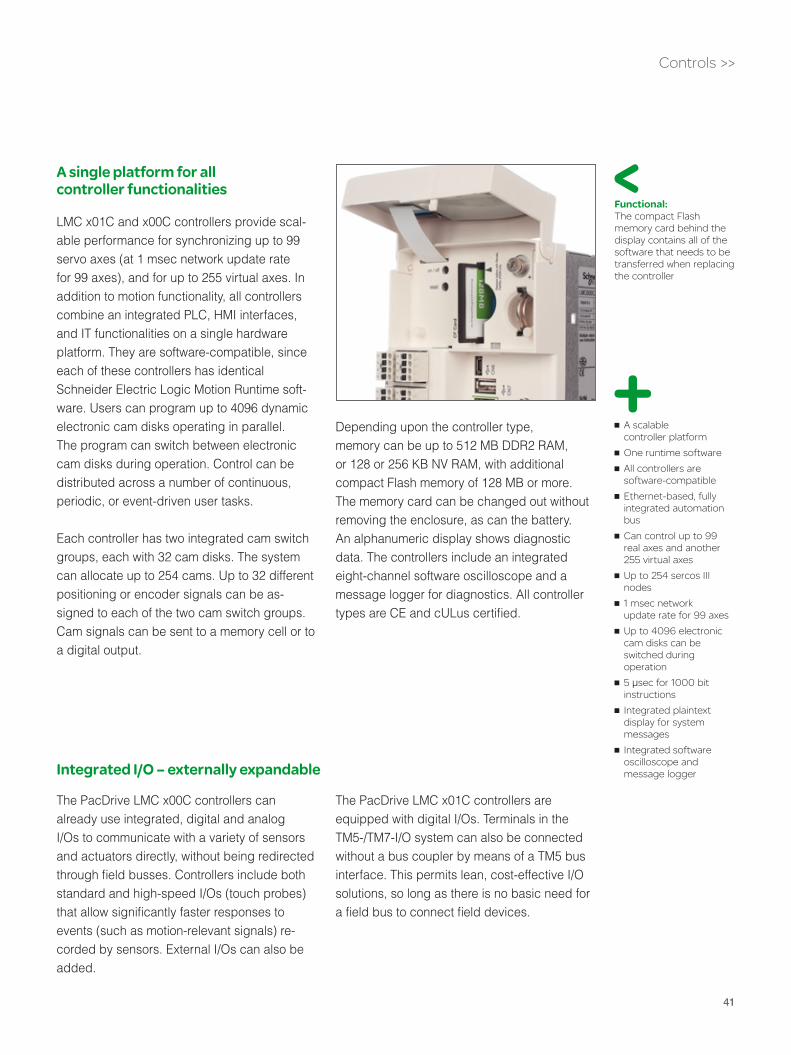
Functional: The compact Flash memory card behind the display contains all of the software that needs to be transferred when replacing the controller
42
Controls >>
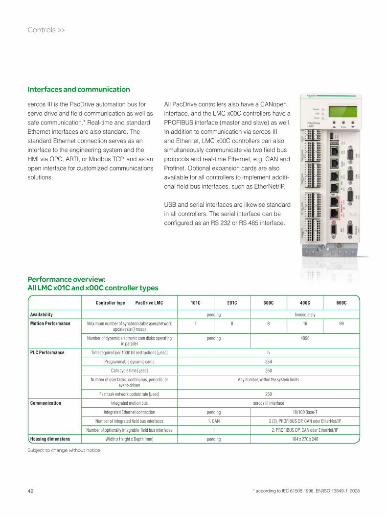
Controller type PacDrive LMC 101C 201C 300C 400C 600C
Availability pending Immediately
Motion Performance Maximum number of synchronizable axes/network update rate (1msec)
4 8 8 16 99
Number of dynamic electronic cam disks operating in parallel
pending 4096
PLC Performance Time required per 1000 bit instructions [µsec] 5
Programmable dynamic cams 254
Cam cycle time [µsec] 250
Number of user tasks, continuous, periodic, or event-driven
Any number, within the system limits
Fast task network update rate [µsec] 250
Communication Integrated motion bus sercos III interface
Integrated Ethernet connection pending 10/100 Base-T
Number of integrated fi eld bus interfaces 1, CAN 2 (3), PROFIBUS DP, CAN oder EtherNet/IP
Number of optionally integrable fi eld bus interfaces 1 2, PROFIBUS DP, CAN oder EtherNet/IP
Housing dimensions Width x Height x Depth [mm] pending 104 x 270 x 240
Performance overview: All LMC x01C and x00C controller types
Subject to change without notice
Interfaces and communication
All PacDrive controllers also have a CANopen interface, and the LMC x00C controllers have aPROFIBUS interface (master and slave) as well.In addition to communication via sercos III and Ethernet, LMC x00C controllers can also simultaneously communicate via two fi eld bus protocols and real-time Ethernet, e.g. CAN and Profi net. Optional expansion cards are also available for all controllers to implement additi-onal fi eld bus interfaces, such as EtherNet/IP.
USB and serial interfaces are likewise standard in all controllers. The serial interface can be confi gured as an RS 232 or RS 485 interface.
sercos III is the PacDrive automation bus for servo drive and fi eld communication as well as safe communication.* Real-time and standard Ethernet interfaces are also standard. The standard Ethernet connection serves as an interface to the engineering system and the HMI via OPC, ARTI, or Modbus TCP, and as an open interface for customized communications solutions.
* according to IEC 61508:1998, EN/ISO 13849-1: 2008

43
Cat5e Baudrate: 100 Mbit/sCycle time: 1 ms ... 4 ms
Vendor-neutral Powerful
Universal
With IEC 61491, sercos established itself as the worldwide communication standard for auto-mation. sercos III uses industrial Ethernet for its transmission physics. More than 50 controller manufacturers and 30 drive manufacturers worldwide support the standard.
Greater bandwidth makes sercos III even faster than sercos II. This allows a network update rate of 1 msec for up to 99 drives. An innova-tive synchronization procedure makes sercos III even more precise than before.
The use of standardized profi les for drive technology, I/O, and communication between controllers (C2C) is increasing the range of possible applications for sercos III. For the fi rst time, sercos can be used as a fully integrated Ethernet-based solution for drive and fi eld bus
communications, including communications in safety automation*. sercos III also permits parallel transmission of standardized or propri-etary IP protocols over a non-real-time channel.
Controls >>
sercos III Automation Bussercos III is the universal automation bus for PacDrive 3: Drive-based communication, I/O communication, and safe communication* can be implemented with the same medium.
Bidirectional full-duplex Ethernet communication Media redundancy to
reduce failure probability Simpler, more
cost-effective design No hubs or switches CAT5e cable is
generally sufficient Complete setup via
software, including assignment of bus addresses
* according to IEC 61508:1998, EN/ISO 13849-1: 2008
44
Safety functions* for the entire machineIn PacDrive 3, standard communication and safe communication* merge into one: sercos III is the shared basis for communication. Components for safety* signal acquisition and safety* dialogue (Page 72) can also be inte-grated into the safety solution* using safe I/O components (Page 46).
Functional Safety
* according to IEC 61508:1998, EN/ISO 13849-1: 2008

45
Ethernet, TCP/IP, OPC, FTP, HTTP, SMS, SMTP
sercos III + Integrated Safety*
Magelis HMI
LMC 101C, 201C, 300C, 400C, 600CLogic Motion Controllers
Other field busses:PROFIBUS DP, CANopen, EtherNet/IP, Profinet , Modbus
IT/COM
Logic Motion
TM7Remote I/O
TM7Remote I/O
TM5 I/O
LXM 62 Multiaxes Servo Drives + Power Supply + ILM 62 CM
Stand-aloneServo DrivesLXM 52
SH
Ethernet, TCP/IP, OPC, FTP, HTTP, SMS, SMTP
sercos III + Integrated Safety*
Magelis HMI
Safe Logic Controller*SLC x00
Motion
IT/COMIT/COM
Logic Motion
ILM 62SH Torque Motor
LinearMotor
Distribution Box
A safety protocol via sercos III enables the complete integration of safe communication into standard communication, without the need for additional dedicated cabling or a safety bus. Safety signals from data acquisition or dialog devices are connected through safety terminals or remote I/Os. A safety controller on the sercos III ring permits programming of the safety functions. Both standard safety functions and safety functions enhanced in accordance with PLCOpen Safety defi nitions can be imple-mented with the integrated solution.
SoMachine Motion Workbench is a program-ming tool for the engineering functions. In addition to the program editor, it also contains tools to set the safety device parameters for functional safety components (drives, I/O components, etc.). The Safe Logic Controller can be programmed directly via the PacDrive controller, which functions as a gateway.
Other classic designs based upon hardwired safety components can of course also be implemented. Please consult with our experts to determine which Preventa products are right for you.
Fully integrated safety solution Reduced installation
costs, no more dedi- cated cabling Integrated Workbench
tool for safety software in IEC 61131-3
Functional Safety >>
* according to IEC 61508:1998, EN/ISO 13849-1: 2008

46
LMC 101C, 201C, 300C, 400C, 600CLogic Motion Controllers
TM5/sercosdistributed I/O island
TM5/...remote I/O island
TM7 IP67 Remote I/O
TM7 IP67 Remote I/O
TM5/...remote I/O island
TM5/...remote I/O island ... up to 25 remote I/O islands
sercos III + Integrated Safety*
IT/COM
Logic Motion
TM5 Bus ... 100m ...≥ 100m ...≥ 100m ...≥ 100m ...≥ ... up to 2500 m
Safe Logic Controller*SLC x00
Flexible and modularThe TM5 I/O system is a modular design for creating distributed I/O solutions on the sercos III automation bus. I/O networks can be built with both line and ring topologies.
One terminal block can include up to 250 individual modules. The basic unit of each I/O island is the sercos III interface, which is plugged into a bus base module together with the fi rst terminal. Additional I/O modules can be snapped to this unit. Each of these modules consists of three basic components: bus base, function unit, and one of the various terminal blocks. The benefi ts of this design include
rapid assembly and a reduced need for spare parts. Functional units that incorporate digital/analog I/Os, mixed-function units, and power supplies are available.
The TM5 system provides additional fl exibility with the option to connect additional remote terminal blocks to a terminal block via the TM5 I/O bus at distances of up to 100 m, using transmitter and receiver units. Up to 25 of these remote I/O units can be connected serially to a terminal block via the TM5 bus. In extreme cases, the range can be extended up to 2.5 km for a distributed I/O solution!
Flexible I/O design: The TM5 I/O bus can connect up to 25 additional remote units to each I/O island, and can bridge a distance of up to 100 m between two remote units.
Rapid I/O communication via sercosThe new sercos III bus interface for the Schneider Electric universal TM5 I/O system lets you create I/O solutions for rapid communication. The TM5 product line offers a variety of products for an individualized approach to designing your I/O solution on the sercos III automation bus.
I/O communication
* according to IEC 61508:1998, EN/ISO 13849-1: 2008

47
Standardized and fastExpandable with IP67 technology or safety terminals*
Communication in the TM5 system corre-sponds to that of sercos III I/O-Profi l V1.1.2. In addition to consolidation of drive and I/O communication on a shared, Ethernet-based medium, the primary advantage of I/O com-munication via sercos is its high transmission speed. With network update rates of up to 1 ms, the system can satisfy even demanding response time requirements.
The TM5 technology in IP 20 provides the necessary basis for connecting the soon-to-be-released, highly compact TM7 modules to a sercos automation bus, and expands the ability of I/O systems to operate under harsh environmental conditions. Safe communica-tion* versions of both TM5 and TM7 modules are available, with special coloring to clearly differentiate them from standard technology. Standard and safe I/O modules can be mixed.
I/O islands in IP67: The TM5 bus can be used to connect TM7 modules in both standard and safe* designs
I/O communication >>
Up to 30 % time savings for assembly, cabling, and commissioning Compact technology,
small footprint Decentralized I/O islands
via TM5 bus TM7 modules for IP67 TM5 and TM7 modules
both available for safe communication*
* according to IEC 61508:1998, EN/ISO 13849-1: 2008
Plug together and snap in: Components can be combined to create both the basis unit with the sercos III interface as well as all additional functional modules, including safety modules*

48
sercos III + Integrated Safety*
CabinetStand-alone Axes
Pos & Speed
CabinetMulti Axes
Pos & Speed
IntegratedMulti Axes
Pos & Speed
Servo drives for flexible configuration of drive architectures The Lexium servo drive design focuses on cost-sensitive areas: Growing control cabinet space requirements and increased mounting and cabling costs are factors that demand new ideas. The modular servo drives of the LXM 62 Series and the integrated ILM 62 drives provide new ways to reduce space requirements for the servo drive solution in the control cabinet and lower costs, particularly for multiaxis applications. Stand-alone drives with an integrated power supply will soon be available for servo drive solutions with self-contained single axes. These drives will also be supplemented with integrated stand-alone drives, as in the multiaxis design.
Flexibleservo drive design:Control-cabinet-basedstand-alone or multiaxisservo drives are supple-mented with integrated variants
Servo Drives, Multiaxis Solutions
* according to IEC 61508:1998, EN/ISO 13849-1: 2008

49
Servo Drives, Multiaxis Solutions >>
The fully digital servo drives of the Lexium LXM 62 series are modular, consisting of single drives (1 axis) and double drives (2 axes) of equal size, as well as power supplies with differing output. All of the single and double drives in a group use a shared power supply. Multiple groups are possible, with the number of axes being limited by the type of controller used.
Lexium LXM 62 lets users implement cost-effective compact multiaxis solutions.The double drives in particular offer signifi cant advantages.
All LXM 62 components offer easy handling and installation, startup, and replacement: The rapid, front side-connection to the power supply automatically includes integration into the DC bus as well. The motor and encoder cables exit at the bottom of the unit, leaving room for easy access at the front of the device.
Integrated design: Power supply and two drive modules, which are only half as wide
Lexium LXM 62 Universal servo drives for multiaxis solutions

50
Motor/encoder cables exit at the bottom of the unit:
Leaves room at the front of the device for rapid
assembly/disassembly of LXM-62 components
Type: LXM 62 DU60A DD15A DD27A DD45A DxxxA DU60B DD15B DD27B
Availability Immediately pending Immediately
Number of synchronizable axes 1 2
Continuous current Aeff (4kHz) 2 5 9 22 50 2 x 2 2 x 5 2 x 9
Peak current Aeff 6 15 27 45 100 2 x 6 2 x 15 2 x 27
Supply voltage [V] Min. 250 V DC, max. 700 V DC
Supply frequency [Hz] 48 ... 62
Control voltage [V] DC 24 V (-20% / +25%)
Inter-faces
Motion bus sercos III
Encoder Hiperface (more available soon)
Inverter Enable 1 input 2 inputs
Digit. inputs 2 2 x 2
Digit. inputs or TP 2 2 x 2
Digit. inputs or outputs 2 2 x 2
Housing dimensions DxWxH [mm] 270 x 44 x 310 270 x 89 x 310 270 x 44 x 310
Protection rating IP 20
Excess voltage category KIII, T2 (DIN VDE 0110)
Excess voltage resistance –
Degree of radio interference –
Certifi cations CE, ULus
Connection to DC bus, 24 V power supply,
and ground wire: Move the slide to the left,
tighten the screws, and it’s done
Fast connection to sercos: Single and double drives are integrated into the sercos ring with short cable bridges.
Technical Data / Servo Drives
Servo Drives, Multiaxis Solutions >>
Subject to change without notice

51
Technical Data / Power Supplies
Type: LXM 62 PD84A Pxxxx
Availability Immediately pending
Continuous current (A) 42 120
Peak current (A) 84 179
Continuous output [kW] 25 67
Peak output [kW] 50 100
Supply voltage [V] 3AC208V (- 10%)…3AC480V (+8%)
Control voltage [V] DC24V (-15% .. +25%)
DC bus voltage [V] DC250V .. DC700V
sercos III interface integrated
Bleeder integrated Recovery planned
EMC-Filter integrated external
Housing dimensions DxWxH [mm]
270 x 89 x 310 270 x tbd x 310
Protection rating IP 20 IP 20
Excess voltage category KIII, T2 (DIN VDE 0110) –
Excess voltage resistance – –
Degree of radio interference – –
Certifi cations CE, ULus
Another innovation is that all servo drives are coupled to the DC bus and to the power supply: No backplane connections are re-quired, and the modules can be coupled to the adjacent module with a front-side quick-con-nect with stop screws in less than two minutes. When the connection is made, LEDs signal proper power supply with the 24 V control voltage. The design functions without any ad-ditional effort, even when drives are taken out and reinstalled from a continuously connected series of devices. LXM 62 Series servo drives
can be used with all PacDrive System motors, both rotary and linear. All servo drives have an electronic name plate. Upon fi rst use or ex-change of the device, it is identifi ed by the cen-tralized controller and confi gured based upon the specifi ed parameters. The servo drives themselves in turn detect connected motors by their name plates. LXM 62 servo drives can be integrated into safety automation designs (in accordance with IEC 61508:1998 SIL2, EN/ISO 13849-1:2008 PL d) by using the Inverter En-able input (or two in the case of double drives).
Less space required in the control cabinet Minimal assembly/
installation time Tool-free motor
connection Optimized feedback
loops minimize contouring errors Safety input Inverter
Enable (pursuant to IEC 61508:1998, EN/ISO 13849-1:2008) for each axis Automatic motor
detection Software-compatible
with integrated servo drives ILM and with stand-alone servo drives
Subject to change without notice
Servo Drives, Multiaxis Solutions >>

52
Multiaxis design requires up to 90 % less control cabinet space Different dimensions,
with peak torques of up to 55 Nm Can be combined with
single and double drives to a shared power supply 70% shorter cable
lengths 90% less wiring required
in the control cabinet 50% less cable
installation required on the machine frame
Integrated Servo Drives
Lexium ILM 62Multiaxis design for consistent modular machine building
Quick interconnects and hybrid cables for signal and power level, automatic network confi guration, and diagnostic functions: The Lexium ILM 62 servo modules with inte-grated drive electronics, which will be released soon, are the technological successors to the iSH servo modules, and offer more than just compact drives. The drive and network solution together form a true plug-and-play solution for modularity in mechanics, electronics, and software.
Servo modules move servo drives out of the control cabinet and into the fi eld. Based upon experiences with iSH technology, this reduces wiring and cabling requirements in the control cabinet by up to 90 %. The only components that remain in the control cabinet are the Pac-Drive controller, the shared power supply for 40 or more servo modules, and the CM (con-nection module). The CM feeds power to the ILM 62 servo modules from the same power supplies as the LXM62. The components, which have compatible dimensions, allow the assignment of ILM servo modules to groups with different safety functions*, for example.
* according to IEC 61508:1998, EN/ISO 13849-1: 2008

53
Integrated Servo Drives >>
Smaller control cabinets: With intelligent servo
modules, the servo drives are mounted in
the machine frame, leaving only the
controller and the shared power supply in the
control cabinet
ILM servo modules use a fl exible approach to cabling, consisting of pre-terminated hybrid cables and distribution boxes. The networkitself is confi gured as a plug-and-play solution. Compared to conventional servo solutions, this reduces the required cabling by up to 70%, and the labor required for installing the servo solution in the machine frame is reduced by approximately 50 %.
ILM servo modules are the key element in modular machine design. They permit modular design of mechanics, software, and even elec-tronics. This makes ILM servo modules an ideal solution for machines with a variety of optional mechatronic modules. Aside from any ad-ditional power supply units required, any later addition of modules to a machine requires no changes in the control cabinet.
ILM servo modules are planned in fl ange sizes of 70, 100, and 140 mm. A 55 mm fl ange will be available later. They will therefore completely cover a holding torque range of 1.1 to 12.5 Nm and/or a peak torque of 3.5 to 55 Nm. The models are software-compatible with one another and with LXM 62 and LXM 52 Series servo drives. Additional options include the integration of a holding brake, a feathered key groove, and a multi-turn encoder with elec-tronic name plate. The addition of a shaft seal can increase the protection rating from IP40 to IP65.
Peak torques of 3.5 to 55 Nm
54
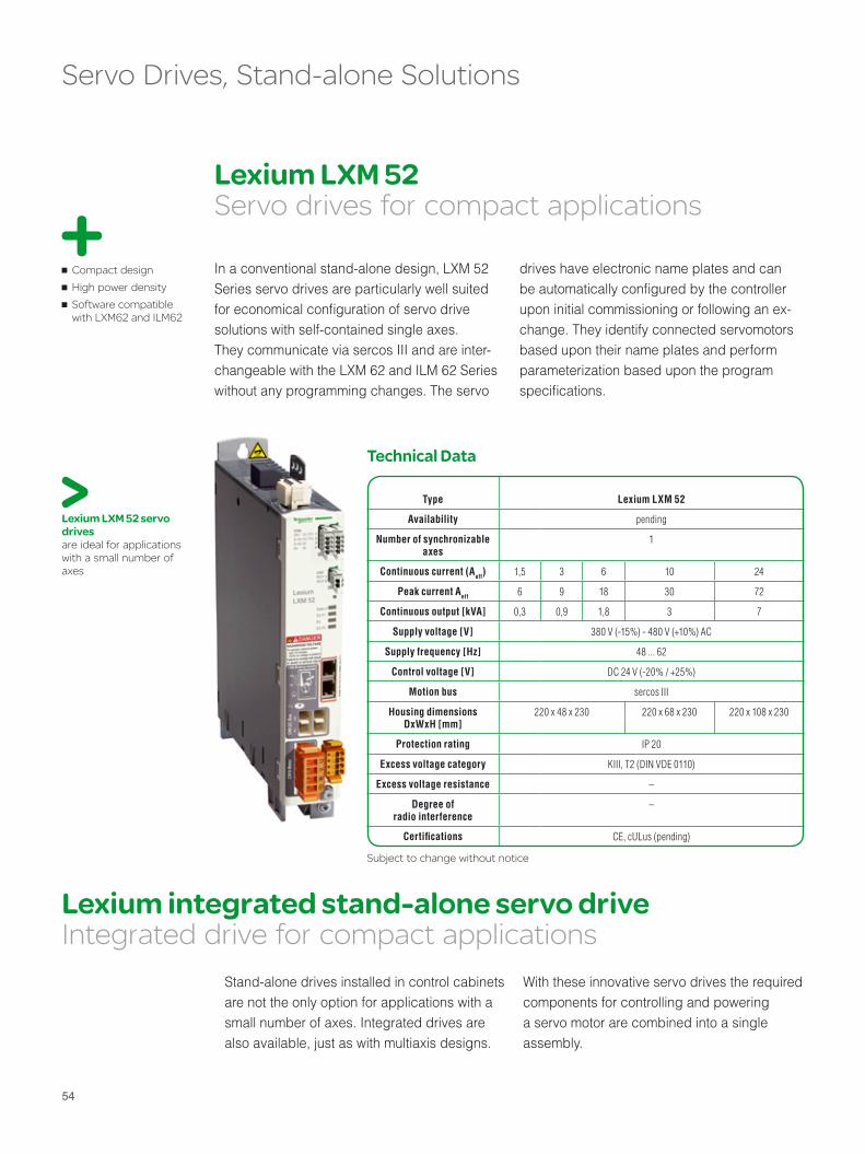
Lexium LXM 52 Servo drives for compact applications
Lexium integrated stand-alone servo drive Integrated drive for compact applications
Type Lexium LXM 52
Availability pending
Number of synchronizable axes
1
Continuous current (Aeff) 1,5 3 6 10 24
Peak current Aeff 6 9 18 30 72
Continuous output [kVA] 0,3 0,9 1,8 3 7
Supply voltage [V] 380 V (-15%) - 480 V (+10%) AC
Supply frequency [Hz] 48 ... 62
Control voltage [V] DC 24 V (-20% / +25%)
Motion bus sercos III
Housing dimensions DxWxH [mm]
220 x 48 x 230 220 x 68 x 230 220 x 108 x 230
Protection rating IP 20
Excess voltage category KIII, T2 (DIN VDE 0110)
Excess voltage resistance –
Degree of radio interference
–
Certifi cations CE, cULus (pending)
Technical Data
Subject to change without notice
Compact design High power density Software compatible
with LXM62 and ILM62
Servo Drives, Stand-alone Solutions
Lexium LXM 52 servo drives are ideal for applications with a small number of axes
In a conventional stand-alone design, LXM 52 Series servo drives are particularly well suited for economical confi guration of servo drive solutions with self-contained single axes. They communicate via sercos III and are inter-changeable with the LXM 62 and ILM 62 Series without any programming changes. The servo
Stand-alone drives installed in control cabinets are not the only option for applications with a small number of axes. Integrated drives are also available, just as with multiaxis designs.
With these innovative servo drives the required components for controlling and powering a servo motor are combined into a single assembly.
drives have electronic name plates and can be automatically confi gured by the controller upon initial commissioning or following an ex-change. They identify connected servomotorsbased upon their name plates and perform parameterization based upon the program specifi cations.


Rotary and linear servo motors Modern, high-speed production machines require highly dynamic, precise AC servo motors with a wide range. Brushless, overload-protected servo motors with high resolution encoders as well as torque and linear motors offer solutions for a variety of applications. All of the servo motor types shown below can be operated by Lexium LXM 52 and LXM 62 servo drives, and thus integrated into synchronized multiaxis systems on the sercos interface.
Servo Motors
56
Low inertia rotor: Lexium SH Series AC motors meet the highest performance requirements
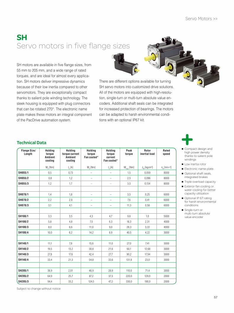
57
Compact design and high power density thanks to salient pole windings Low inertia rotor Electronic name plate Optional shaft seals,
integrated brakes Triple overload capacity Exterior fan cooling or
water cooling for better capacity utilization Optional IP 67 rating
for harsh environmental conditions Single-turn or
multi-turn absolute value encoder
SH motors are available in fi ve fl ange sizes, from 55 mm to 205 mm, and a wide range of rated torques, and are ideal for almost every applica-tion. SH motors deliver impressive dynamics because of their low inertia compared to other servomotors. They are exceptionally compact thanks to salient pole winding technology. The sleek housing is equipped with plug connectors that can be rotated 270°. The electronic name plate makes these motors an integral component of the PacDrive automation system.
There are different options available for turning SH servo motors into customized drive solutions. All of the motors are equipped with high-resolu-tion, single-turn or multi-turn absolute value en-coders. Additional shaft seals can be integrated for increased protection of bearings. The motors can be adapted to harsh environmental condi-tions with an optional IP67 kit.
Servo Motors >>
Technical Data
Subject to change without notice
Flange Size/Length
Holdingtorque
Ambientcooling
M0 [Nm]
Holdingtorque current
Ambientcooling
I0 [A]
Holdingtorque
Fan cooled*
M0 [Nm]
Holdingtorquecurrent
Fan cooled*
I0 [A]
Peak torque
Mmax [Nm]
Rotor inertial load
JM [kgcm²]
Rated speed
nN [min-1]
SH055/1 0,5 0,73 – – 1,5 0,059 8000
SH055/2 0,8 1,2 – – 2,5 0,096 8000
SH055/3 1,2 1,7 – – 3,5 0,134 8000
SH070/1 1,4 1,8 – – 3,5 0,25 6000
SH070/2 2,2 2,9 – – 7,6 0,41 6000
SH070/3 3,1 4,1 – – 11,3 0,58 6000
SH100/1 3,3 3,5 4,3 4,7 9,6 1,0 5000
SH100/2 5,8 4,8 7,5 6,3 18,3 2,31 4000
SH100/3 8,0 6,6 11,0 9,0 28,3 3,22 4000
SH100/4 10,0 6,2 14,2 8,9 40,5 4,22 3000
SH140/1 11,1 7,8 15,6 11,0 27,0 7,41 3000
SH140/2 19,5 13,2 30,8 21,6 60,1 12,68 3000
SH140/3 27,8 17,6 42,4 27,7 90,2 17,94 3000
SH140/4 33,4 21,3 54,8 33,6 131,9 23,0 3000
SH205/1 36,9 2,01 46,9 28,9 110,0 71,4 3000
SH205/2 64,9 25,7 87,2 37,3 220,0 129,0 2000
SH205/3 94,4 33,2 124,5 47,2 330,0 190,0 2000
SHServo motors in five flange sizes

58
Direct drivesHigh precision with minimal wear
Highly dynamic drives Linear drives reduce
wear and tear Direct drives generally
deliver high precision Engineering support
available upon request for drive selection and application
Servo Motors >>
In contrast to conventional drive solutions, rotary and linear direct drives generate torque precisely where it is needed in the machine. The absence of detours through gears or belts allows the generation of signifi cant torque. It also reduces the space requirements for drive components, and eliminates parts that may be subject to mechanical wear and tear. Benefi ts include less maintenance and greater reliability. Because of its superior dynamics when compared with other drive solutions, direct drive technology offers improved machine performance in many cases.
PacDrive can be used to integrate rotary and linear direct drives into synchronized multiaxis systems. Both motor types can be operated with standard Lexium LXM 52 and Lexium LXM 62Series servo drives. The benefi ts of these motors can be utilized even with high-speed machines having demanding synchronization requirements.
In contrast to standard servos, both direct drive models generally require more precise tuning and/or adaptation to a specifi c application. We therefore recommend that customers consult with our expert teams of application engineers and motor specialists when selecting suitable motor types.
If necessary, we can even provide assistance on integrating the motors into your application. This helps reduce risks when getting started with direct drive technology.
Direct drive technology for PacDrive:
Lexium servo drives can operate a wide range of
linear and torque motors

59

60
Integrated RoboticsThe integration of robotics into the machine control solution is one of the outstanding aspects of the PacDrive automation system. On the software side, the integration of robots is made simpler by an IEC-compliant library with Equipment Modules (EMs) and Application Function Blocks (AFBs) for motion programming and transformationto all commonly used kinematics. Thanks to the availability of complete robot arm mechanics, development of customer-specific kinematics or integration of third-party products is no longer necessary. This permits even faster creation of robot-enabled machine designs.
Robotics Solutions

61
Cartoner
Robot
Grouping
Dual BeltInfeed Conveyor Belt
In/Out
Robot Robot
IT/COM
Logic Motion
Ethernet, TCP/IP, OPC, FTP, HTTP, SMS, SMTP
LMC x00CLogic Motion Controller
sercos III + Integrated Safety
SoMachineMotion
Safe Logic Controller*SLC x00
Robotics Solutions >>
The PacDrive system supports an almost unlimited variety of kinematic confi gurations, allowing robotics to become an integral part of a machine‘s automation architecture. High-performance PacDrive controllers are capable of synchronizing up to 99 axes in a real-time multiaxis system. From the controller perspective, therefore, a robot is reduced to a motion con-trol system with a corresponding number of servo axes, which can operate under demanding real-time conditions. In this way, the controller can manage one or more robots in addition to other machine functions within an IEC 61131-3-compliant program.
Integral automation architecture
Easy software integration thanks to AFB and EM libraries
Transformation modules for PacDrive and standard kinematics
The integration of robots into the PacDrive automation solution software drastically reduces the number of complex software algorithms. The robots are mapped onto a software module, which is then inserted into modular, IEC-61131-3-compliant program structures, just as with other mechatronic machine modules. This structure is based upon library Function Blocks that are parameterized by the user or “fed“ with motion data in the form of a program or a table. Once the motion paths have been defi ned, parameters can be specifi ed in order to limit the acceleration forces that act on the trans-ported product. The option to specify blending parameters provides further potential for optimizing the motion paths. The controller performs all of the other functions, including actuation of the robot axes, based upon library Function Blocks.
In the PacDrive robotics solution, motion program-ming and its transformation to robot kinematics are separate processes. This means that the robot kinematics can be selected independently of the generated motion program. Regardless of whether the project uses standard kinematics de-veloped by the customer or third-party suppliers, or PacDrive mechanics (Delta-2, Delta-3, gantry, and portal kinematics are currently available), the appropriate transformation module adapts the selected solution to the motion program.
In principle, the available transformation mod-ules can be used to adapt all typical 2 to 6-axis systems.
One controller can control machines and multiple robots Software integration
using Function Block library Integrated IEC
61131-3-compliant software, no additional programming tools Easy access to process
parameters One HMI concept for
machines and robots Transformation modules
for popular robotic kinematics such as Gantry, Scara, Portal, Articulated, Delta
* according to IEC 61508:1998, EN/ISO 13849-1: 2008
Integration of robots in the automation architecture:Depending upon the number of axes, kinematics, speed, and other requirements, one PacDrive LMC 600 C controller, for example, can control between six and 30 robots, each with three axes

62
Delta 2 Delta 3
Gantry Portal
Scara
Robotics Solutions >>
In addition to transformation modules mapped to these kinematics, a universal transforma-tion module is also available for custom-designed or third-party kinematics to allow various robots to be controlled with Pac-Drive controllers
Motion transformation: Appropriate transforma-tion modules incorporate all typical kinematics into the controller software, whether it involves PacDrive robotics or customized kinematics
Articulated

63
* up to a maximum of 3.5 kg with reduced acceleration ** including rotational axis in the R version
Type P4s-F / P4s-R P4i-F / P4i-R
Load capacity 1,5 [kg]*
Max. speed 10 [m/sec]
Max. acceleration at 1kg 100 [m/sec2]
Max. acceleration at 1.5kg 75 [m/sec2]
Number of axes 3 (4**)
Repeatable position accuracy +/- 0,1 [mm]
Work envelope height 225 / 350 [mm]
Work envelope diameter 1200 / 750 [mm]
Work envelope rotation* Unlimited
Protection rating IP 65 –
Subject to change without notice
Robotics Solutions >>
The P4 delta3 robot, featuring full stainless steel construction, is designed for pick & place applications. The software includes a prepro-grammed interface for integration of the most commonly encountered vision solution. The P4 can be equipped with an optional rotational axis (P4s-R). The P4 robot arm is driven by conventional motors with cabinet-mounted servo drives (P4s-F or P4s-R) or by intelligent servo modules with integrated control electron-ics (P4i-F or P4i-R). Thanks to their IP 65 rated washdown confi guration, the P4s-F and the P4s-R are also suitable for hygienic environ-ments. The P4 is also available in an ISO 14644-1-certifi ed Class 6 cleanroom design.
Everything fi ts together: Robot mechanics, servo systems, and the robotics library provide a ready-to-use solution. In addition, complete packages, including engineering, can accelerate the integration of robotics into an application.
PacDrive P4 Complete robotics packages for Delta 3kinematics
P4 delta-3 robot kinematics: With standard motors, available in washdown configuration up to IP 65

64
The modular linear motion system consists of basic elements and complete solutions for a variety of 1, 2, and 3 dimensional motion tasks. Thanks to its modular structure, the elements can be confi gured as needed. The length and stroke of each axis system is individually determined.
Portal axes in various sizes, with timing belt drive or spindle drive as desired, can move loads of up to 100 kg. The structural elements of these linear tables are extremely rigid, and the overall assembly has very compact dimen-sions. Cantilever axes with round rods or a profi le design are particularly well suited for limited spaces. Thanks to the fi xed motor and moving body of the axis, cantilever axes can move fl exibly into the work envelope.
Double-axis systems move loads with great fl exibility and speed across distances of up to 5 1/2 meters. They also serve as a basis for complete solutions involving multidimensional motion tasks.
The MAX P linear positioner, a combination of double-axis system and cantilever axis, moves up to 50 kg with a high level of precision.
The MAX R portal robot with two servo axes and the MAX R 3 with three servo axes are the top-of-the-line designs for the modular linear motion system. A rotational axis can also be integrated as an option.
For variants with up to fi ve axes, PacDrive of-fers pre-programmed or adaptable transforma-tion modules to integrate robotic solutions into a machine’s program structure.
Linear Motion Single and multiaxis systems for linear motion
Portal axes: Left: PAS S (spindle drive), center: PAS B (timing belt drive), and right: TAS linear table
MAX P linear positioner: The combination of double axis system and cantilever axes can be mounted both above and below the workspace
Cantilever axes: Left: CAS (round rod axis), right: CAS 4x (profile axis)
MAX H two-axis system: Designed for positioning over long distances
Robotics Solutions >>

65
Technical Data
Mechanics packages available for linear axes up to three-axis portal Compatible
components Support and service
from a single source for the entire automation solution Complete package of
mechanics and engineering support available upon request
Robotics Solutions >>
Portal robot MAX R2 or R3: This robot is used for applications mounted over the work envelope as either an x-y or an x-y-z unit, depending upon requirements.
Subject to change without notice
Single-axis systems
PAS B PAS S TAS CAS
Portal axis Portal axis Linear table Cantilever Telescoping axis
Design Profi le Round rod Profi le
max. load [kg] 100 100 150 50 18 35
max. stroke [mm] 5500 3000 1500 1200 500 2400
Positioning speed [m/s] 8 1,25 1 5 2 5
Guides Roller bearings/ball bearings
Ball bearings Recirculating ball bearings
Roller bearings/Recir-culating ball bearings
Recirculating ball bearings
Roller bearings/Recir-culating ball bearings
Version – – – Profi le Round rod Profi le
Drive element Timing belt Spindle Spindle Timing belt Timing belt
Double-axis and Multi-axis systems
MAX H MAX S MAX P MAX D MAX R2 MAX R3
Double-axis system Linear positioner Portal robot
Axes 1 1 2 2/2 2 3
max. load [kg] 250 300 50 2/5 137 50
max. stroke in x [mm] 5500 5500 5500 300/700 5500 5500
max. stroke in y [mm] – – – – 1500 1500
max. stroke in z [mm] – – 1200 150/300 – 1200

66
Operator interfaces with display panels from 3.8” to 19” The variety of product shapes offered by the Magelis program with its Small and Advanced Panels opens up a wide range of HMI design possibilities. An ARTI driver simplifies the engineering phase for integrating PacDrive 3 solutions by providing direct access to the runtime system variables.
The right size for the right display: Magelis HMI panels allow users to create custom-ized solutions with less engineering time
HMI

67
Ethernet, TCP/IP
Magelis HMI
Vijeo Designer
LMC 101C, 201C, 300C, 400C, 600CLogic Motion Controllers
IT/COM
Logic Motion
Hardware variety
Touchpanels, keyboard entry devices Detachable solutions
and handheld devices Different operating
systems Optimal integration into
PacDrive 3 solutions with ARTI drivers
Vijeo Designer confi guration software can be used to uniformly implement Magelis-based HMI solutions. An ARTI protocol driver reduces engineering time by building a bridge directly from the confi guration tools to the controller
application. This provides direct access to run-time system variables, which can then be easily browsed using the confi guration tool. The oth-erwise typical additional defi nition of variables for the HMI application is no longer required.
Efficient Engineering
Depending upon the model, Magelis HMI systems are available in display sizes ranging from 3.8” to 19”. Different hardware features open up possibilities for individual applications: Touchscreen panels with VxWorks, Windows XP, or XP embedded are available for standard operating systems. Solutions with separate display monitors and their associated hardware or handheld devices offer still more alterna-tives. Flexible confi gurations with application memory and/or memory cards for fl exible mem-ory expansion as well as a variety of interfaces make it easy to integrate display panels into your applications.
Direct access: An ARTI protocol driver is the basis for high-speed communications between the HMI panel and the con-troller, with access to the runtime system variables
Easy connection: Magelis HMI display panels include most popular interfaces
HMI >>

68
Field Bus Devices
Automation components on the field busAs an alternative to integrated Ethernet-based communication, PacDrive 3 also offers dual-track designs with conventional field buses. In this case, sercos III is the bus for communication with the servo drives. Field devices can be integrated into the automation solution via CAN, PROFIBUS DP, or other field bus standards. Positioning solutions, variable frequency drives, and motor protection components communicating via field bus supplement the automation solution to meet specific application needs. With PROFIBUS, CANopen and DeviceNet connections, the range of products covers all customary IP 20 and IP 67 rated I/O configurations.

69
Field Bus Devices >>
40% less wiring required 25% less cabling
required Flexibility thanks to three
possible motor technologies Can be used with
popular field buses Simple installation and
commissioning Integrated safety*
thanks to safety* function Safe Torque off (STO)
pursuant to IEC/EN 61800-5-2
The Lexium line of integrated drives combines the motor, positioning control, power electronics, fi eld bus, and the “Safe Torque Off*” safety* function in a single assembly. Three variants are available:
The Lexium ILA, with a servo motor, delivers a high degree of dynamics. It generates high torque even during acceleration. Different winding types are available for application-specifi c requirements.
The Lexium ILE, with an electronically commutated motor, offers a high degree of fl exibility. The 3-phase synchronous electronically commutated brushless DC motor has a high holding torque of up to 8 Nm (with spur gear drive), often eliminating the need for a holding brake. The integrated electronics communicate absolute position to the automation controller.
The Lexium ILS, with a step motor, is the most precise of the three. The 3-phase step motor generates high torque at low speeds. This often eliminates the need for a gear reduction, permitting space saving direct drive solutions. The Lexium ILS is the solution for high resolu-tion positioning with good synchronization. Commissioning involves little effort – the user merely needs to adjust the power supply.
All integrated Lexium drives can communicate via CAN, EtherNet/IP, or Profi bus DP.
Lexium ILxIntegrated Positioning Drives
Technical Data
Motor
Speed range [rpm] (direct
drive)
[1/min]
Continuous torque
(direct drive)
[Nm]
Peak torque
(direct drive)
[Nm]
Encoder Holding brake
Optional gearing
ILA servo motor drive < 7500 < 0,26 < 1,62 High-resolution encoder (16384 increments)
Yes Planetary gear unit (Gear ratios from 3:1 to 40:1)
ILE EC motor drive < 5000 < 0,24 < 0,80 Hall sensors No Cylindrical and planetary gear unit (Gear ratios from 18:1 to
115:1)
ILS step motor drive < 2000 < 6 < 6 With or without index pulse encoder (optional)
Yes Planetary gear unit (Gear ratios from 3:1 to 8:1)
Subject to change without notice
Lexium integrated drives: Three variants with three different motors
* according to IEC 61508:1998, EN/ISO 13849-1: 2008

70
Technical Data
Altivar type
ATV 312 ATV 32 ATV 71
Power range in kW(50…60 Hz power supply)
Single-phase 200…240 V 0,18…2,2 0,18…2,2 0,37…5,5
3-phase 200…240 V 0,18…15 0,18…15 0,37…75
3-phase 380…480 V – – 0,75…1300
3-phase 380…500 V 0,37…15 0,37…15 –
3-phase 525…600 V 0,75…15 – –
3-phase 500…690 V – – 2,2…2000
Output frequency in Hz – 0,5…500 0,1…599 1…1600 Hz to 37 kW, 1…500 Hz from 45...500 kW
Short-term overload moment in % of the rated motor moment
for 2 s 200 200 220
for 60 s 170 170 170
Subject to change without notice
Wide performance range Integrates easily into
PacDrive solutions CANopen integrated,
additional field bus options available for ATV 71 and 32
Field Bus Devices >>
The Altivar family of variable frequency drives offers the right drive speed controller for different applications. Like the ATV 32, the Altivar 312 is appropriate for simple machines with a power range of up to 15 kW. For more complex machines with higher performance, the Altivar 71 with its power range of 0.37 to 1300 kW is the right solution.
The Altivar 312, 32, and 71 series are well suited for areas such as packaging, transporta-tion, conveyors, positioning systems, or textile machines. This makes them ideal for PacDrive automation solutions. Time-saving Function Blocks for integrating these frequency drives are provided in the PacDrive software library.
All models can communicate via Modbus or CANopen, and all can be connected to Profi bus, Ethernet IP, and DeviceNet through integrated communication cards. Versions with connection via sercos III are pending.
Altivar: Variable frequency drives for both simple and com-plex machines; pictured are the ATV 312, 32, and 71 models
Altivar 312/32/71 Variable frequency drives

71* according to IEC 61508:1998, EN/ISO 13849-1: 2008
Plug-and-play without encoder systems and commissioning software. Excellent
synchronization High torque even at
low rotational speeds Integrated safety
functionality (STO)*
Field Bus Devices >>
Lexium SD328 step motor drives: Compact plug-and-play solutions with minimal space requirements in the control cabinet
The Lexium SD328 step motor drive is a powerful positioning solution for communication via Profi bus, CAN, and CANopen. The different variants are designed for holding torques of 1.7 to 19.7 Nm. The safety function “Safe Torque Off” (STO pursuant to IEC 61800-5-2) is already inte-grated in the device. Drives are available for up to 6.8 A. The SD328 is suitable for a power supply with 1~115 VAC and 230 VAC (50/60 Hz). A power fi lter is integrated, and the current is reduced automatically at zero speed. The SD328 can also be equipped with motion monitoring on request.
Lexium SD328Step motors on the field bus
Technical Data
3-phase step motor
Type
Step motor drive 115 V/230 V
Type
Holding torque at zero speed
[Nm]
Maximum torque
[Nm]
Maximum speed (RPM)
[1/min]
BRS368Wx
SD328 x U25 (2,5 A)
1,7 1,5 2000
BRS397Wx 2,3 2,0 2000
BRS39AWx 4,5 4,0 2000
BRS39BWx 6,8 6,0 2000
BRS3ACWxSD328 x U68 (6,8 A)
13,5 12,0 2000
BRS3ADWx 19,7 16,5 2000
Subject to change without notice
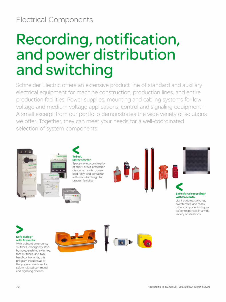
72
Recording, notification, and power distribution and switchingSchneider Electric offers an extensive product line of standard and auxiliary electrical equipment for machine construction, production lines, and entire production facilities: Power supplies, mounting and cabling systems for low voltage and medium voltage applications, control and signaling equipment – A small excerpt from our portfolio demonstrates the wide variety of solutions we offer. Together, they can meet your needs for a well-coordinated selection of system components.
Electrical Components
TeSysU Motor starter:Space-saving combination of short-circuit protection disconnect switch, over-load relay, and contactor, with modular design for greater flexibility
Safe signal recording* with Preventa:Light curtains, switches, switch mats, and many other components trigger safety responses in a wide variety of situations
Safe dialog* with Preventa:With pullcord emergency switches, emergency stop buttons, enabling switches, foot switches, and two-hand control units, this program includes all of the popular solutions for safety-related command and signaling devices
* according to IEC 61508:1998, EN/ISO 13849-1: 2008

7373
Electrical Components >>
Altistart 01 and 48: Soft starters for AC induction motors and three-phase AC induction motors for 0.18 to 630 kW, ideal for use in combina-tion with Altivar ATV 312 and ATV 71 frequency converters
GV3 motorstarter and protector:Triggers at motor currents of 9 to 65 A, with thermo-magnetic or magnetic triggers if needed
Harmony control and signaling devices: Signaling technology as well as a series of lighted and unlighted pushbuttons, switches, and much more
Control cabinets and enclosures: Wide range of sizes, materials, and installation accessories
OsiSense - Recording systems and sensors:A complete range of sensors – optoelectronic, inductive, or ultrasound recording as well as positioning switches – for most industrial automation applications
OsiSense XG:Open and extremely compact RFID system for all popular ISO data media based on the 13.56 MHz standard

74
PacDrive 3 and the Competition
Compare for yourselfThe complexity of power automation systems and the number of individual factors involved often make it difficult to directly compare one system with another. Use our checklist to decide for yourself which of the strengths offered by PacDrive are important for you, and compare these with what our competitors offer.

75
User benefi t PacDrive 3
International assistance available
International assistance is standard at Schneider Electric, one of the world’s largest suppliers of automation technology and electrical equipment.
Complete solutions from a single source
Complete automation solutions, electrical equipment, installation, mechatronics, SCADA and MES systems
Support 24/7 Help line
Open standards Programming design is IEC 61131-3 compliant, IEC standards for fi eld bus communication, international IT standards for vertical integration or remote maintenance
Sustainability PC Intel platform, long-term availability of controllers, drives, and motors
Universal controller functionality of the hardware platform
PLC, motion, and IT functionality, no additional and/or proprietary controller hardware required for the complete machine (incl. robotics)
Scalability Up to 99 servo drives, software can be ported between platforms
Ethernet-based automation bus sercos III, manufacturer-neutral and IEC standard
Diagnostic functionalities Up to motor shaft thanks to electronic name plates in motors and drives, message loggers, software oscilloscope for simultaneous display of PLC and motion variables
Simulation Programs can be tested without real axes by using centralized controller architecture
Flexible design of servo drive architectures
Stand-alone servo drives, multiaxis system with single/double drives and shared power supply, servo drives with integrated controllers to be released soon
Broad range of servo motors High-performance standard motors, torque motors, and linear drives for a wide range of torque
Safety design* Standard solution available, integrated solution with safety PLC*, safe communication and safe I/Os* via sercos III to be released soon
Rapid installation and commissioning
Plug-and-play technology thanks to electronic name plates in servo system components, hot-plugging of components on motion bus, extensive use of plug connectors
Remote maintenance Remote maintenance via IP connection and diagnostic tools
Integrated tool design Complete workbench with tools for the entire engineering process, for functional safety*, commissioning and diagnosis, central database, and multiuser design for simultaneous work on projects
Tool for motion design Graphic motion design, drivetrain design, and power supply analysis in a single tool, VDI motion rules available
Machine diagnostics Software tool diagnostics integrated into SoMachine Motion Workbench, can also be used separately from Workbench (available free of charge)
Support of modular machine designs Programming tools completely designed for modular program structures, standardized software structures with optional use of the PacDrive programming template (Machine Pilot)
Function Blocks for creating the machine program
PacDrive Libraries with AFBs for basic motion, PLC, cam disk, and technology functions, mathematical functions, torque handling, dual-belt and multi-belt mechanisms, infeed, HMI applications, simulation and testing (ETest), etc.
Function Blocks for program standardization
PacDrive Libraries with AFBs for ANSI/ISA S88 Technical Report (OMAC/PackML), Weihenstephan standard, and FDA, as well as operating mode, error and error response management, process control, predefi ned commissioning screens
Function Blocks at the machine/machine module level
Operating modes, error and error reaction management, process control, predefi ned commissioning resources in the HMI
Hardware and software integration of robotics in machines
Robots are controlled by the machine‘s centralized PacDrive Controller, no additional controller hardware. Software integration with IEC 61131-3-compliant library Function Blocks for path generation, path optimization,transformation to all popular kinematics, as well as synchronization with conveyor belts, products, and other robots
Robots Complete robotics kinematics packages are available, including drives, electronics, and software
* according to IEC 61508:1998, EN/ISO 13849-1: 2008
PacDrive 3 and the Competition >>

Head Offi ce35, rue Joseph MonierF-92500 Rueil-MalmaisonFrance
VM08
141-
001
| 110
4-EN
The information provided in this documentation contains general descriptions and/or technical charac-teristics of the performance of the products contained herein. This documentation is not intended as a substitute for and is not to be used for determining suitability or reliability of these products for specifi c user applications. It is the duty of any such user or integrator to perform the appropriate and complete risk analysis, evaluation and testing of the products with respect to the relevant specifi c application or use thereof. Neither Schneider Electric nor any of its affi liates or subsidiaries shall be responsible or liable for misuse of the information contained herein.
Schneider Electric Industries SAS www.schneider-electric.com
April 2011