the future of fpga interconnect guy lemieux the university of british columbia tuesday, december 8,...
Post on 21-Dec-2015
214 views
TRANSCRIPT
The Future of FPGA Interconnect
Guy LemieuxThe University of British Columbia
Tuesday, December 8, 2009FPT 2009 Workshop
Getting the LUT-heads to work…
2
Layman’s viewpoint
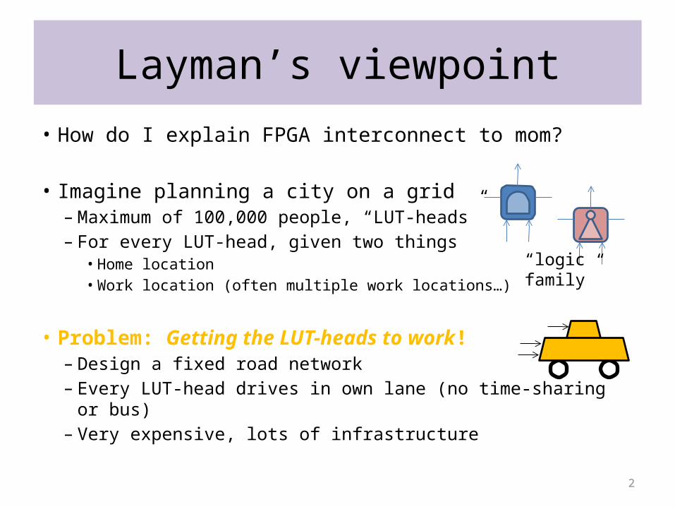
• How do I explain FPGA interconnect to mom?
• Imagine planning a city on a grid– Maximum of 100,000 people, “LUT-heads”– For every LUT-head, given two things
• Home location• Work location (often multiple work locations…)
• Problem: Getting the LUT-heads to work!– Design a fixed road network– Every LUT-head drives in own lane (no time-sharing or bus)– Very expensive, lots of infrastructure
“logicfamily”
3
Layman’s viewpoint (2)
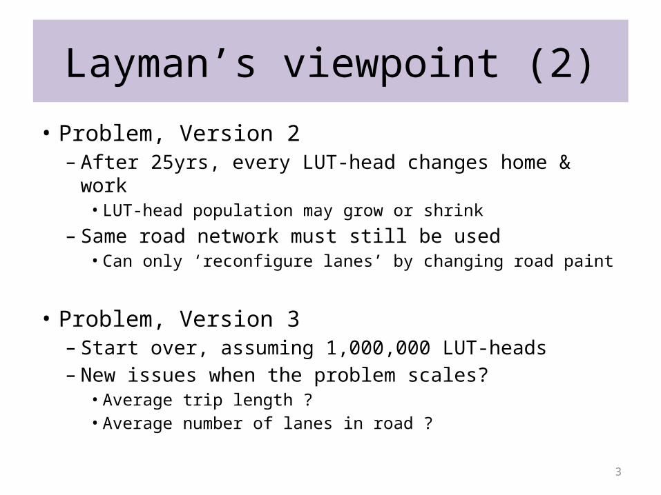
• Problem, Version 2– After 25yrs, every LUT-head changes home & work
• LUT-head population may grow or shrink
– Same road network must still be used• Can only ‘reconfigure lanes’ by changing road paint
• Problem, Version 3– Start over, assuming 1,000,000 LUT-heads– New issues when the problem scales?
• Average trip length ?• Average number of lanes in road ?
4
Overview
• What’s in FPGA interconnect?– Review of typical design
• What are the main application areas?– Driving the future of interconnect design
• What are the interconnect metrics?– Pushing the envelope, then becoming practical
• Open research problems?– Driving the future of interconnect design
5
Overview
• What’s in FPGA interconnect?– Review of typical design
• What are the main application areas?– Driving the future of interconnect design
• What are the interconnect metrics?– Pushing the envelope, then becoming practical
• Open research problems?– Driving the future of interconnect design
6
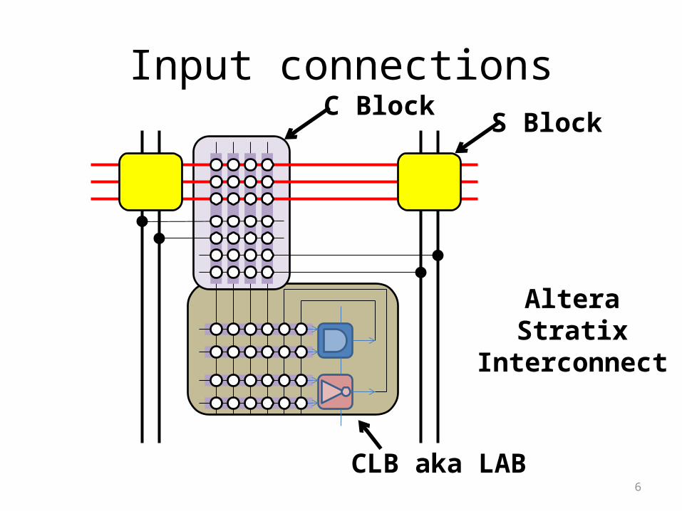
Input connectionsS Block
C Block
AlteraStratix
Interconnect
CLB aka LAB

7
Input connectionsIIB: input interconnect block
AlteraStratix
Interconnect
8
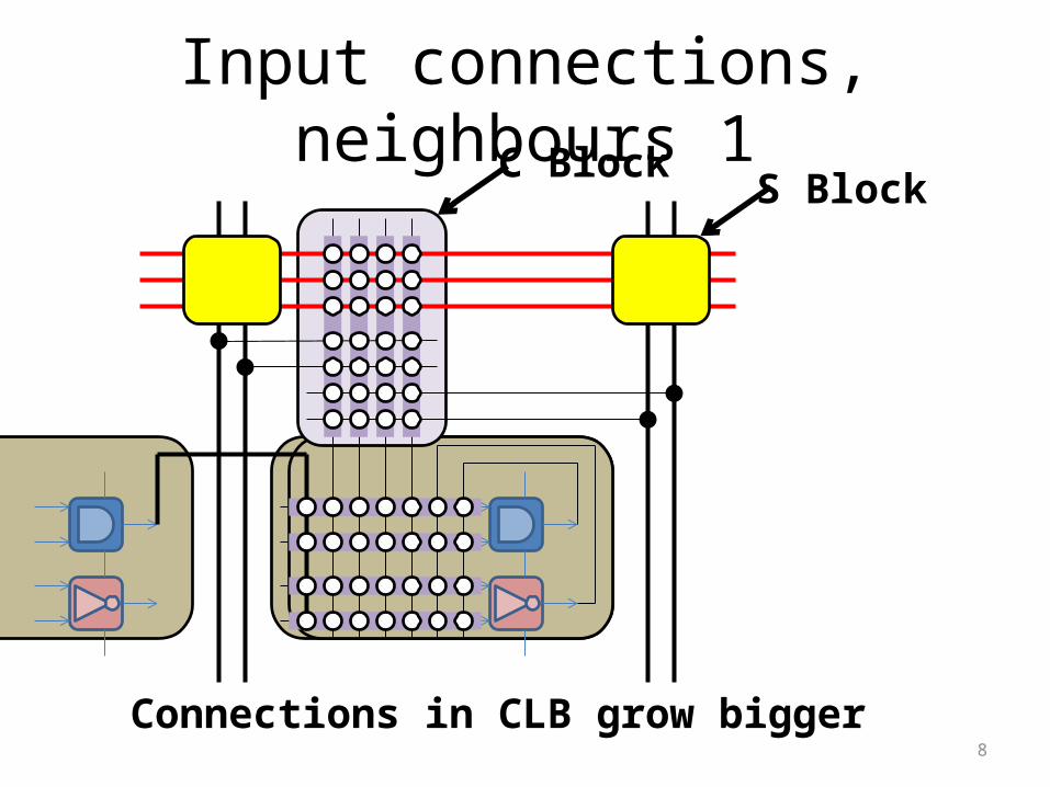
Input connections, neighbours 1S Block
C Block
Connections in CLB grow bigger
9
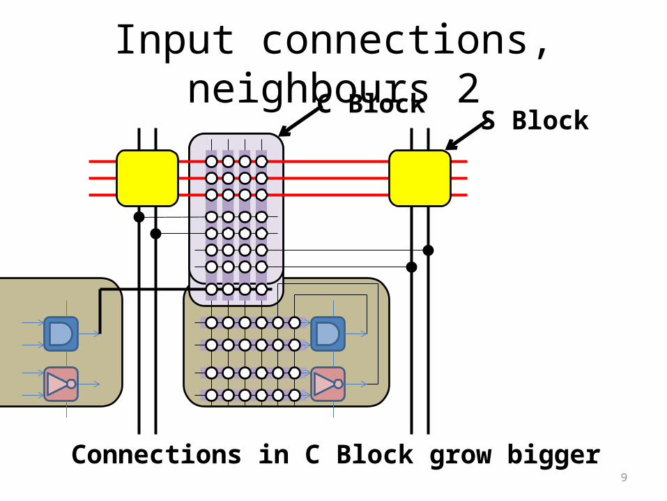
Input connections, neighbours 2S Block
C Block
Connections in C Block grow bigger
10
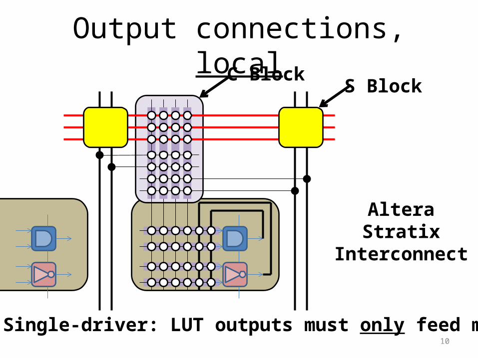
Output connections, localS Block
C Block
AlteraStratix
Interconnect
Single-driver: LUT outputs must only feed muxes
11
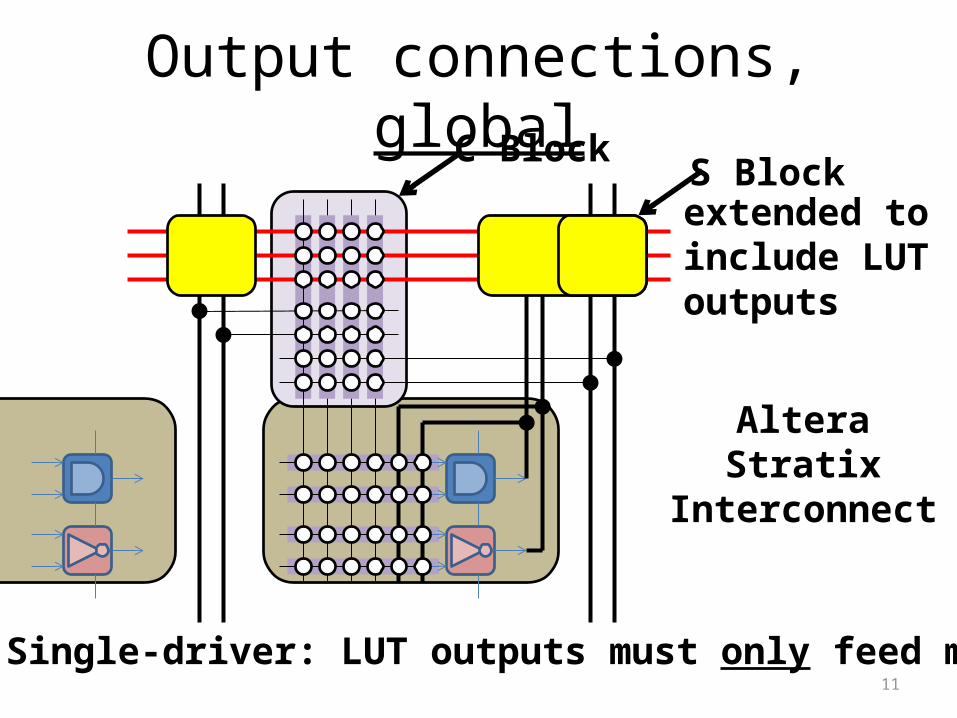
Output connections, globalS Block
C Block
AlteraStratix
Interconnect
Single-driver: LUT outputs must only feed muxes
extended toinclude LUToutputs
12
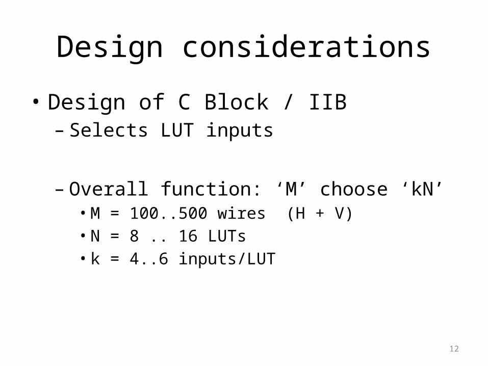
Design considerations
• Design of C Block / IIB– Selects LUT inputs
– Overall function: ‘M’ choose ‘kN’• M = 100..500 wires (H + V)• N = 8 .. 16 LUTs• k = 4..6 inputs/LUT
13
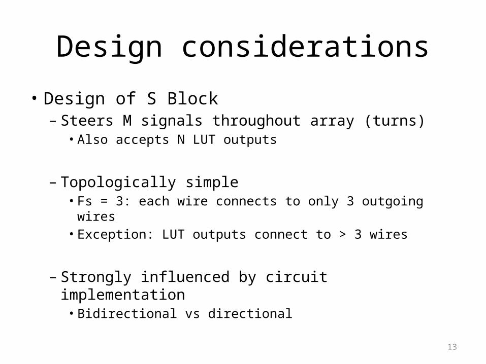
Design considerations
• Design of S Block– Steers M signals throughout array (turns)• Also accepts N LUT outputs
– Topologically simple• Fs = 3: each wire connects to only 3 outgoing wires• Exception: LUT outputs connect to > 3 wires
– Strongly influenced by circuit implementation• Bidirectional vs directional
Bidirectional vs. Directional Wiring
bidir/dir == S Block Design+
single-driver == C Block Design
16
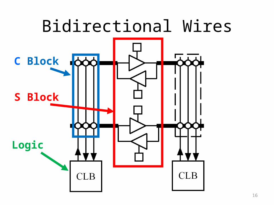
Bidirectional Wires
Logic
C Block
S Block

17
Bidirectional WiresProblem
Half of tristatebuffers leftunused
Buffers +input muxesdominateinterconnect area

18
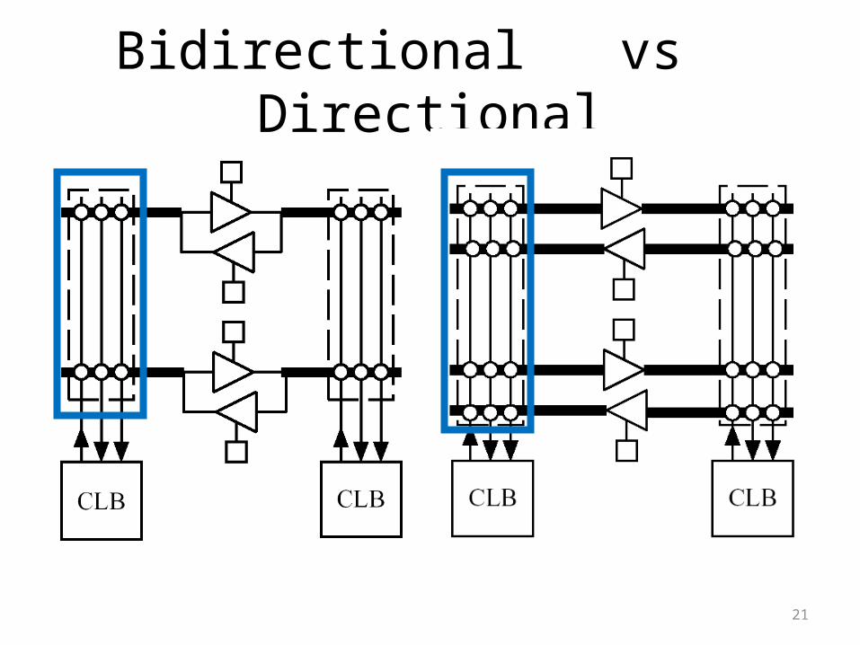
Bidirectional vs Directional
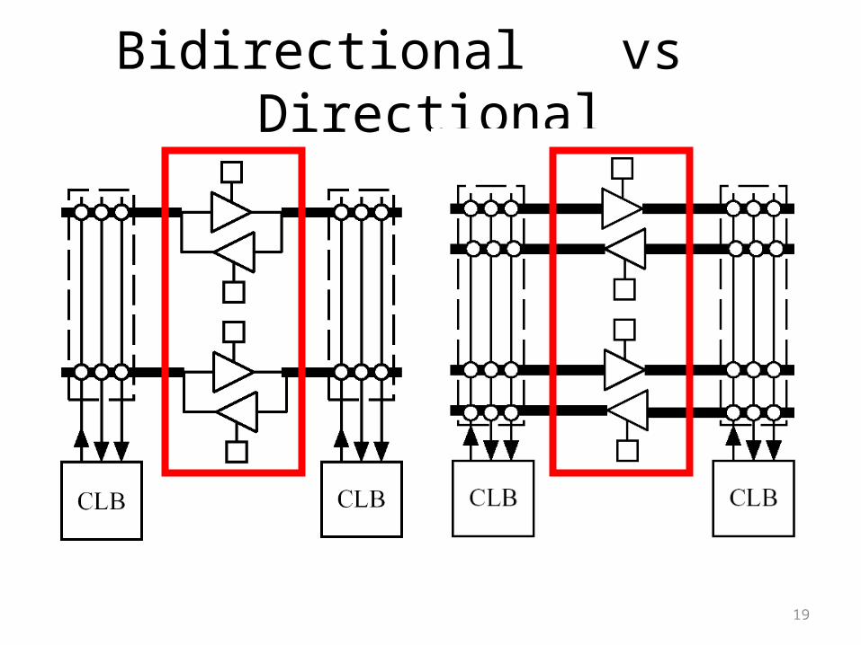
19
Bidirectional vs Directional
20
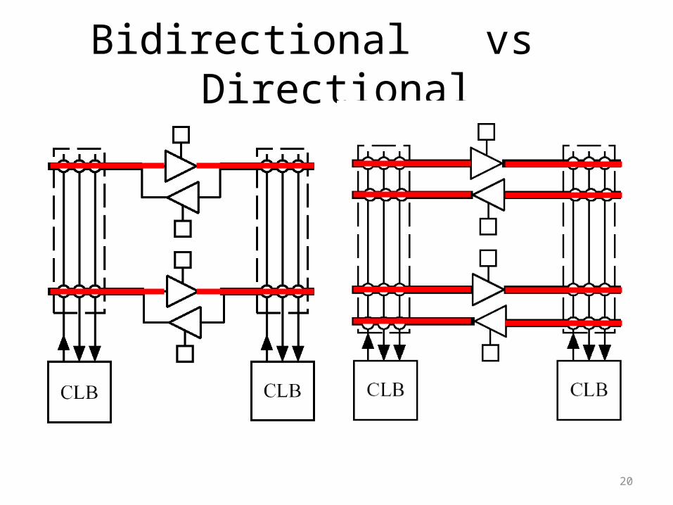
Bidirectional vs Directional
21
Bidirectional vs Directional
22
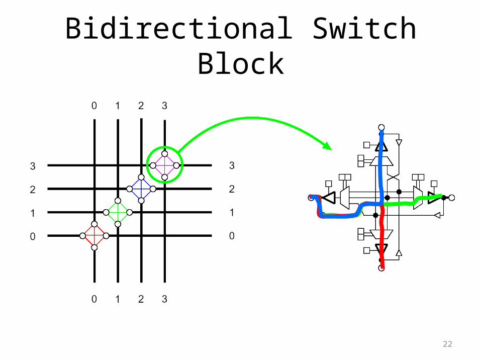
Bidirectional Switch Block
23
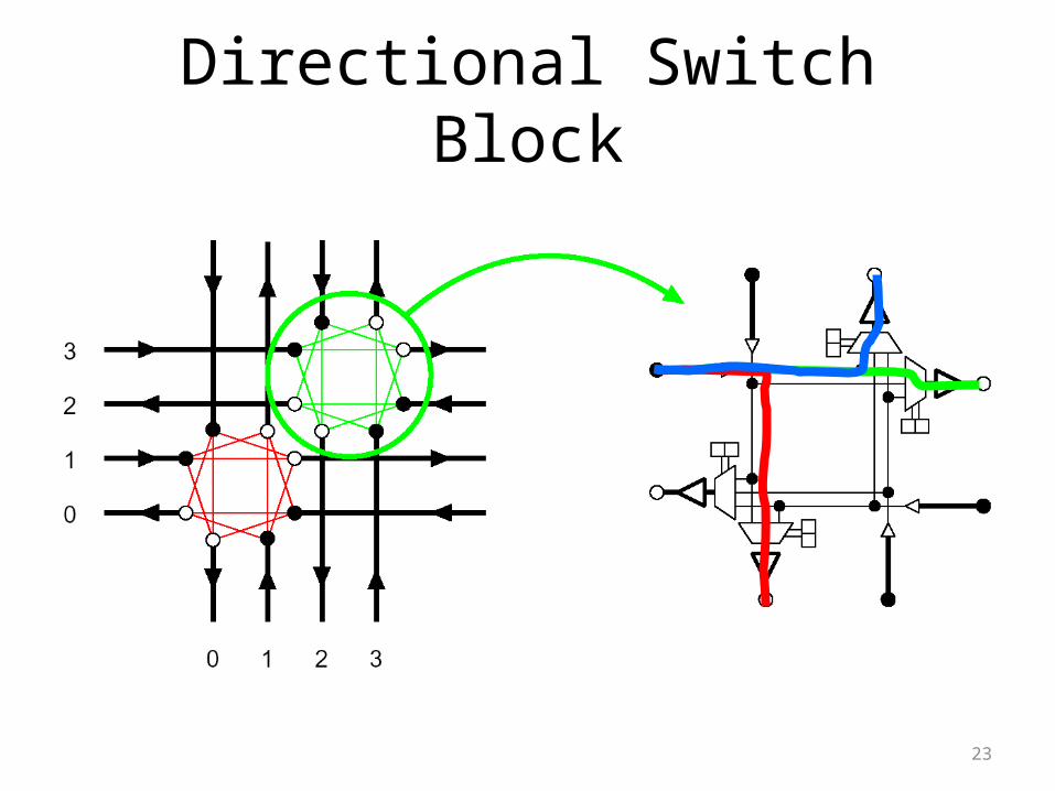
Directional Switch Block

24
Bidirectional vs Directional
Switch Element
Same quantity and type of
circuit elements, twice the wiring
Switch Block
Directional half as many
Switch Elements
25
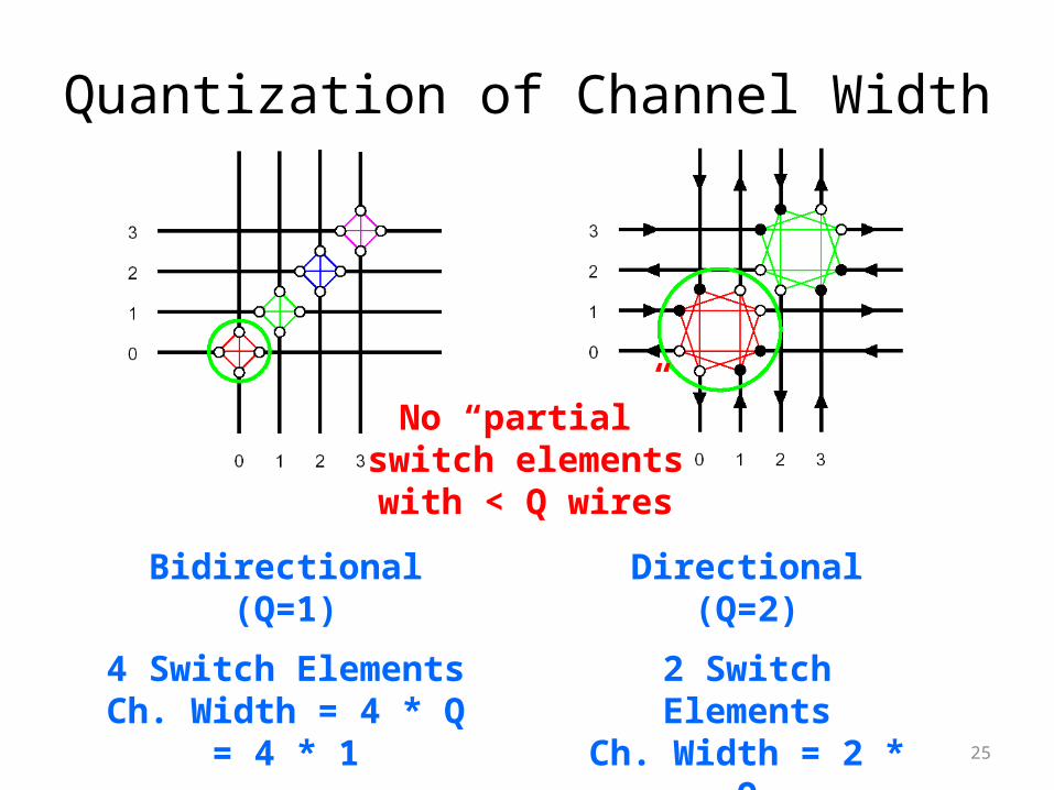
Quantization of Channel Width
Bidirectional (Q=1)
4 Switch ElementsCh. Width = 4 * Q
= 4 * 1
Directional (Q=2)
2 Switch ElementsCh. Width = 2 * Q
= 2 * 2
No “partial”switch elementswith < Q wires
26
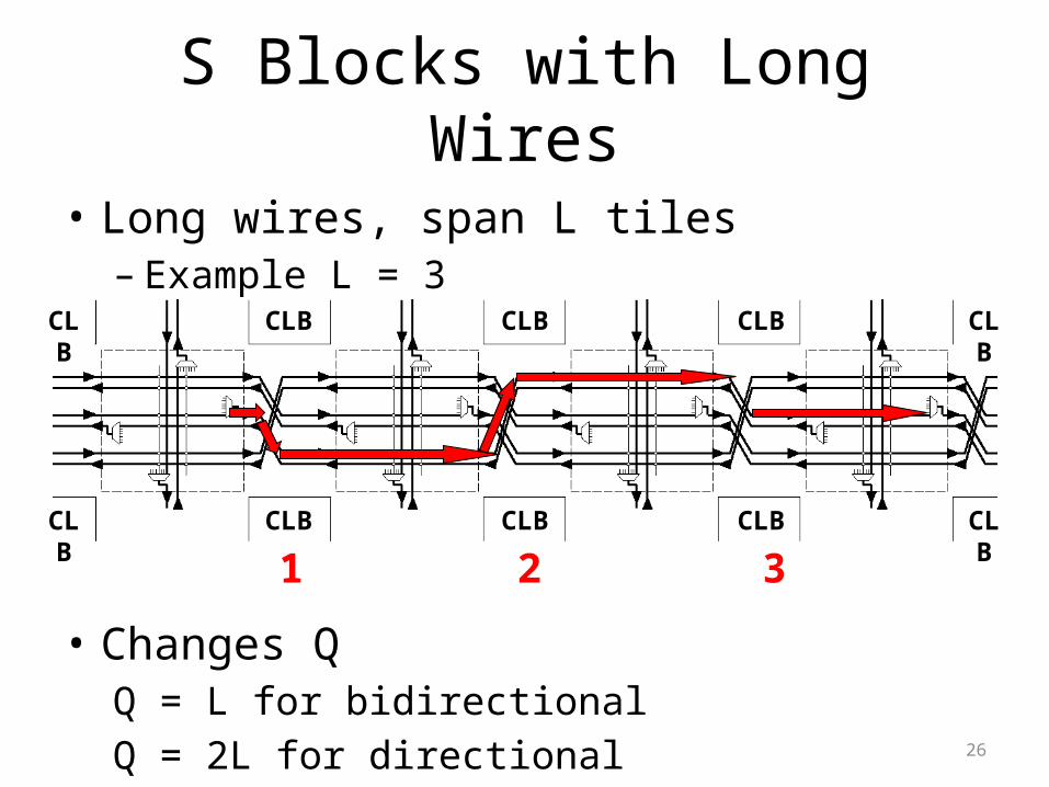
S Blocks with Long Wires
• Long wires, span L tiles– Example L = 3
• Changes QQ = L for bidirectionalQ = 2L for directional
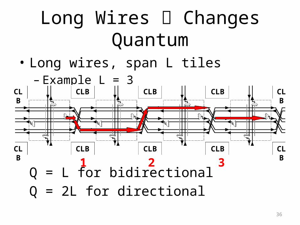
1 2 3
CLB CLBCLB
CLB CLB CLB
CLB
CLB
CLB
CLB

27
Building up Long WiresStart with One Switch Element
Wire ends for straight connections.
CLB
CLB
CLB
CLB
28
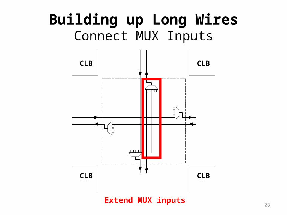
Building up Long WiresConnect MUX Inputs
Extend MUX inputs
CLB
CLB
CLB
CLB
29
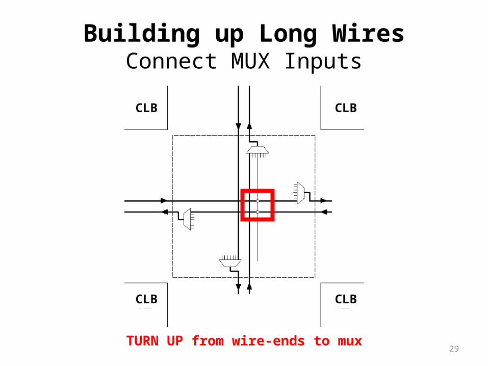
Building up Long WiresConnect MUX Inputs
TURN UP from wire-ends to mux
CLB
CLB
CLB
CLB

30
Building up Long WiresConnect MUX Inputs
TURN DOWN from wire-ends to mux
CLB
CLB
CLB
CLB

31
Building up Long WiresAdd +2 More Wires (4 total)
Add LONG WIRES, turning UP and DOWN.
CLB
CLB
CLB
CLB
32
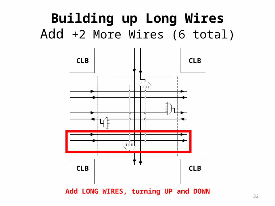
Building up Long WiresAdd +2 More Wires (6 total)
Add LONG WIRES, turning UP and DOWN
CLB
CLB
CLB
CLB
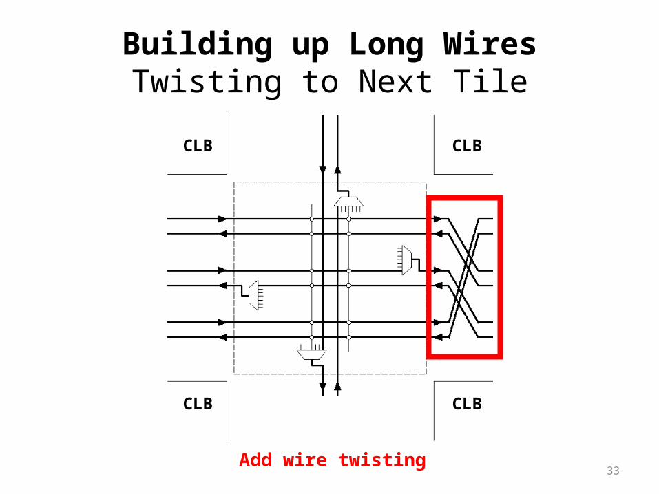
33
Building up Long WiresTwisting to Next Tile
Add wire twisting
CLB
CLB
CLB
CLB

34
CLB
CLB
CLB
CLB
Full S Block with Long WiresUsing One L=3 Switch Element (Q = 2L = 6)
35
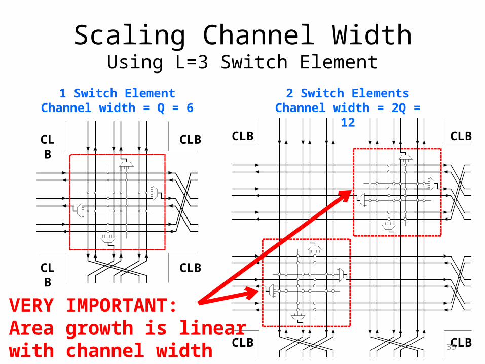
Scaling Channel WidthUsing L=3 Switch Element
CLB
CLB
CLB
CLB
CLB
CLB
CLB
CLB
2 Switch ElementsChannel width = 2Q = 12
1 Switch ElementChannel width = Q = 6
VERY IMPORTANT:Area growth is linearwith channel width
36
Long Wires Changes Quantum
• Long wires, span L tiles– Example L = 3
Q = L for bidirectionalQ = 2L for directional
1 2 3
CLB CLBCLB
CLB CLB CLB
CLB
CLB
CLB
CLB

37
Multi-driver WiringLogic outputs use tristate buffers (C Block)
Directional &multi-driverwiring
C BlockS BlockS Block
CLB
38
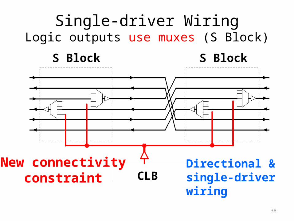
Single-driver WiringLogic outputs use muxes (S Block)
Directional &single-driverwiring
New connectivityconstraint
S BlockS Block
CLB
39
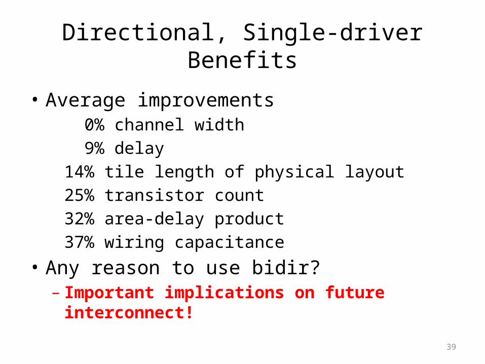
Directional, Single-driver Benefits
• Average improvements 0% channel width 9% delay14% tile length of physical layout25% transistor count 32% area-delay product37% wiring capacitance
• Any reason to use bidir?– Important implications on future interconnect!
40
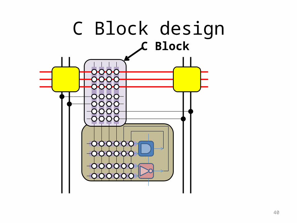
C Block designC Block
41
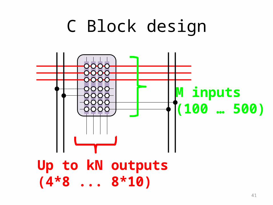
C Block design
M inputs(100 … 500)
Up to kN outputs(4*8 ... 8*10)
42
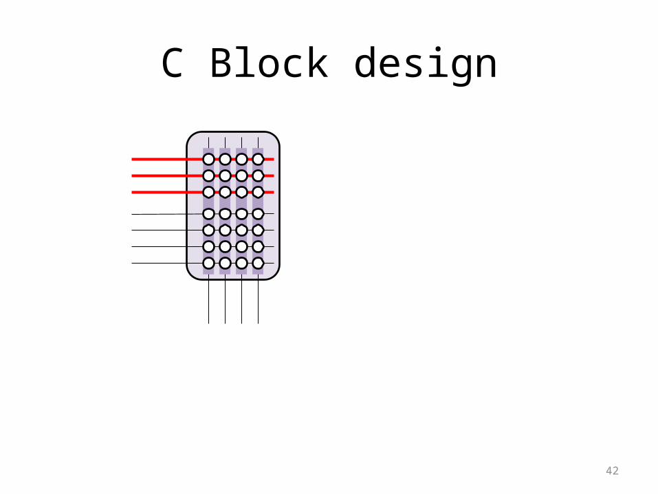
C Block design

43
C Block design
• Sparse crossbar• Similar # switchpoints– On inputs– On outputs
• Spread out pattern– Two columns have
maximum Hamming distance (most # of different switch points)
– True for all pairs of columns
44
Overview
• What’s in FPGA interconnect?– Review of typical design
• What are the main application areas?– Driving the future of interconnect design
• What are the interconnect metrics?– Pushing the envelope, then becoming practical
• Open research problems?– Driving the future of interconnect design
45
What are the main application areas?
• What are FPGAs used for?– A long long time ago… small glue logic
• Modern…– Internet routers (table lookups, multiplexing)– Embedded systems design (NIOS II, MicroBlaze)– Cell phone basestations (communications DSP)– HDTV sets / set-top boxes (video/image DSP)
• Future?
46
Application drivers
• What we know– FPGAs increasingly more powerful, constant cost– ASIC design costs escalating wildly• Most ASICs use older technology (0.18/0.13mm)• Increasingly, ASICs implemented as FPGAs instead
– FPGAs only in low-volume• E.g., being designed-out of HDTV sets
• Extrapolate to find new emerging markets …
47
Application drivers (2)
• Extrapolating…– Industrial/scientific instruments: low volume, high margin
• Medical sensing, imaging (ultrasound, PET, …)• Electronics test & measurement (router tester, …)• Physics (neutrino detection, …)
– Computation: mixed volume, mixed margin• Computer system simulation (RAMP, …)• Molecular dynamics, financial modeling, seismic / oil & gas
– Portable/handheld: mixed volume, mixed margin• Consumer• Industrial/Medical
48
Application drivers (3)
• Problems with FPGAs– Expensive for high-volume markets
• Need cost-reduction strategy
– Insufficient capacity• Could just wait for Moore’s Law to catch up• Capture emerging markets early: ultra-capacity FPGA
– Hard to program• Particularly important when used for computation• Domain-specific languages help
– Power– Slow

49
Overview
• What’s in FPGA interconnect?– Review of typical design
• What are the main application areas?– Driving the future of interconnect design
• What are the interconnect metrics?– Pushing the envelope, then becoming practical
• Open research problems?– Driving the future of interconnect design
50
Interconnect metrics
• Typical– Area– Delay (latency)– Power
• Obscure, but important!– Co$t– Bandwidth– Programmability/Ease of use– Reliability/Integrity– Flexibility/Runtime reconfigurability

51
Pushing the envelope
• Research is about discovery, ideas, exploration– Also evaluation, limit studies, potential uses
• One general research strategy– Pick a metric– Push the envelope• How far did you get?
– Back off until practical– Re-integrate with reality
52
Pushing the envelope (2)
• Example: Area– Cyclone/Spartan are low-cost (low-area) FPGAs
• Push area to the limits?– Reduce every routing buffer to 1x inverter– Extensive use of pass transistor switches– Reduce connectivity, force sparse logic– Bit-serial logic + routing for datapath
• How small can we get?– Is this practical? Is there a market? Is it cost-effective? – Increased parallelism? Prototype future FPGA designs now?
53
Pushing the envelope (3)
• Example: Bandwidth– Virtex/Stratix are high-performance FPGAs
• Push bandwidth to the limits?– E.g., pipeline every routing wire / switch– Use registers or wave-pipeline
• How much throughput can we get?– Wave-pipelining ~5Gbps in 65nm [FPGA2009]– Is this practical? Is there a market?
54
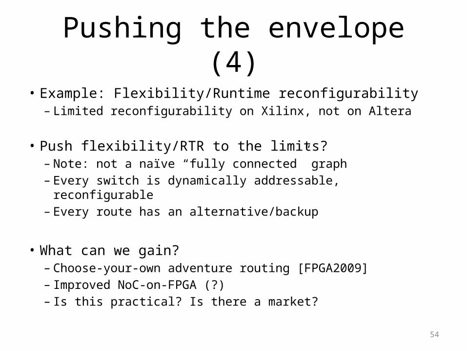
Pushing the envelope (4)
• Example: Flexibility/Runtime reconfigurability– Limited reconfigurability on Xilinx, not on Altera
• Push flexibility/RTR to the limits?– Note: not a naïve “fully connected” graph– Every switch is dynamically addressable, reconfigurable– Every route has an alternative/backup
• What can we gain?– Choose-your-own adventure routing [FPGA2009]– Improved NoC-on-FPGA (?)– Is this practical? Is there a market?
55
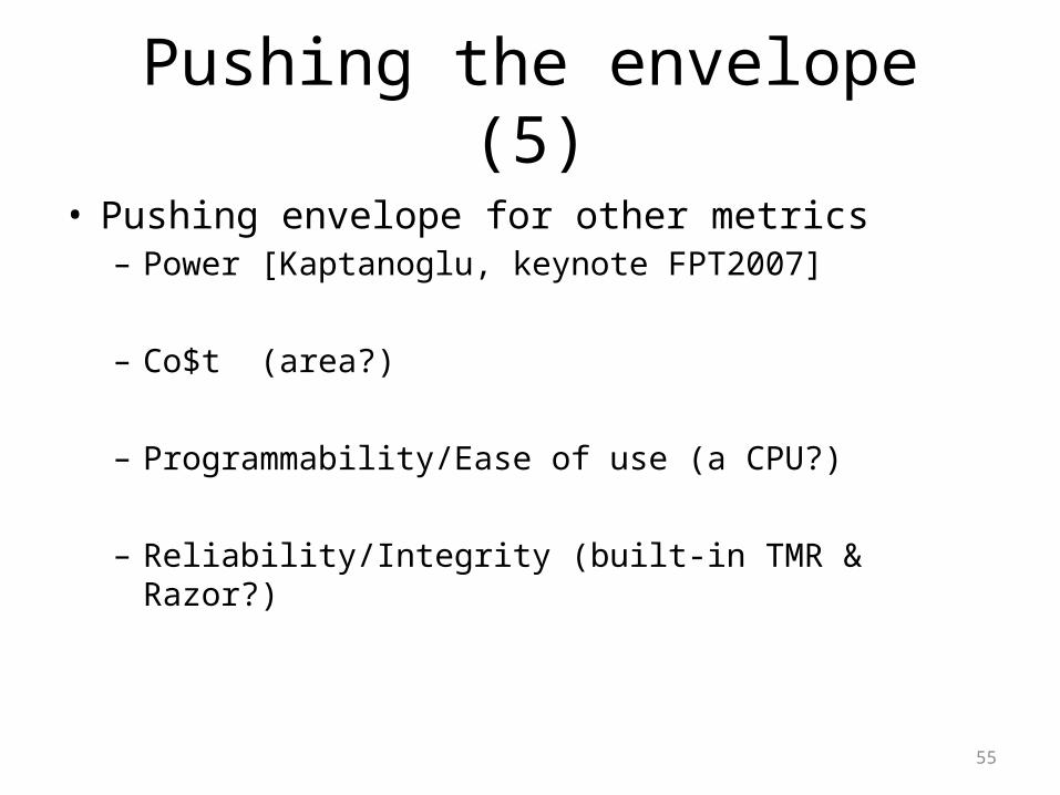
Pushing the envelope (5)
• Pushing envelope for other metrics– Power [Kaptanoglu, keynote FPT2007]
– Co$t (area?)
– Programmability/Ease of use (a CPU?)
– Reliability/Integrity (built-in TMR & Razor?)
56
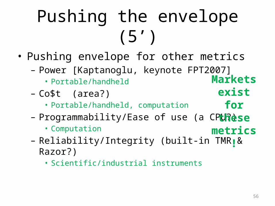
Pushing the envelope (5’)
• Pushing envelope for other metrics– Power [Kaptanoglu, keynote FPT2007]
• Portable/handheld
– Co$t (area?)• Portable/handheld, computation
– Programmability/Ease of use (a CPU?)• Computation
– Reliability/Integrity (built-in TMR & Razor?) • Scientific/industrial instruments
Markets exist for
these metrics!
57
Overview
• What’s in FPGA interconnect?– Review of typical design
• What are the main application areas?– Driving the future of interconnect design
• What are the interconnect metrics?– Pushing the envelope, then becoming practical
• Open research problems?– Driving the future of interconnect design
58
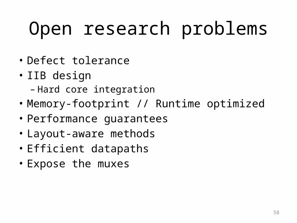
Open research problems
• Defect tolerance• IIB design– Hard core integration
• Memory-footprint // Runtime optimized• Performance guarantees• Layout-aware methods• Efficient datapaths• Expose the muxes• Low-latency, area-efficient repeaters/switches
59
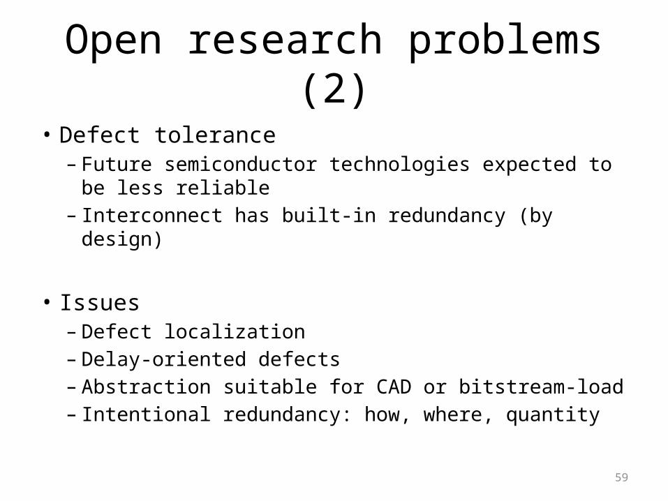
Open research problems (2)
• Defect tolerance– Future semiconductor technologies expected to be less
reliable– Interconnect has built-in redundancy (by design)
• Issues– Defect localization– Delay-oriented defects– Abstraction suitable for CAD or bitstream-load– Intentional redundancy: how, where, quantity
60
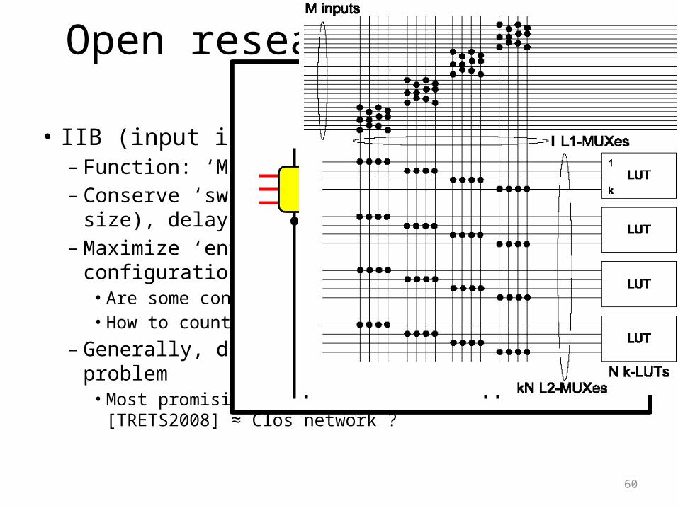
Open research problems (3)
• IIB (input interconnect block) design– Function: ‘M’ choose ‘kN’– Conserve ‘switchpoints’, area (# muxes, mux size),
delay (levels)– Maximize ‘entropy’ == # of unique functional
configurations• Are some configurations more important than others?• How to count # of configurations?
– Generally, difficult topological design problem• Most promising ‘type 3’ IIB
[TRETS2008] ≈ Clos network ?
IIB: input interconnect block
M inputs
kN outputs

61
Open research problems (4)
• Hard core integration– Heterogeneous instance of IIB design problem
• Issues– Each hard core has different # inputs, # outputs
• Complicates uniformity
– Some have large # inputs, outputs• Creates congestion ‘pinch points’• Need to design for ‘worst case’ routability
– Would prefer ‘average case’
62
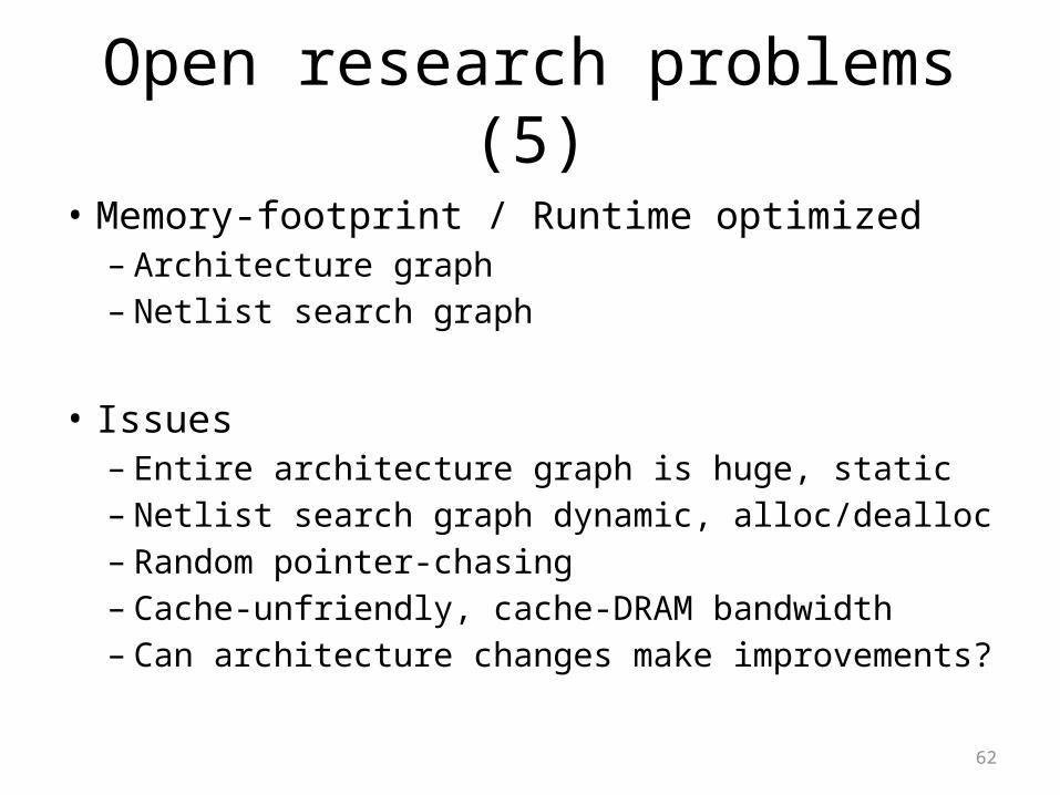
Open research problems (5)
• Memory-footprint / Runtime optimized– Architecture graph– Netlist search graph
• Issues– Entire architecture graph is huge, static– Netlist search graph dynamic, alloc/dealloc– Random pointer-chasing– Cache-unfriendly, cache-DRAM bandwidth– Can architecture changes make improvements?

63
Open research problems (6)
• Performance guarantees– FPGA routers work well, nobody complains• Thank you, PathFinder [McMurchie & Ebeling]
• Issues– Not guaranteed to find a solution (no detection!)• Want ‘Just (unoptimally) route it!’ algorithm
– No performance bounds on metrics• Within X% tracks, Y% delay from minimum
64
Open research problems (7)
• Layout-aware methods– Altera, Xilinx know how to lay out interconnect– 10+ levels of metal, metal-over-switches, integration
of switches and logic• Issues– Arbitrary ‘topology’ graphs not practical to build– “One size fits all” FPGA diminishing
• “Application-specific” FPGA likely to arrive
– Automated layout, automated circuit design tools• Aware of FPGA architecture / structure
65
Open research problems (8)
• Efficient datapaths– Multi-bit connections; same source, same sink– Datapath connections coherent, seemingly simple– Very common in computation designs
• Issues– No successful datapath circuit-switched architecture
• Dedicated datapath interconnect only 5-10% smaller• Abandon circuit switching? power
– How wide? 4b, 8b, 32b?– How to build?
66
Open research problems (9)
• Expose the muxes (1)– LUTs terrible for implementing multiplexers
• 2 x 4LUTs = 1 x 6LUT = 4:1 mux• Imagine 54b barrel shifter (IEEE double-precision)• 1 CLB ≈ 8 x 6LUTs ≈ 2 x 16:1 muxes
– Interconnect is full of muxes• 1 CLB ≈ 60 x 16:1 muxes
• Issues– How to ‘expose’ interconnect muxes to users?– Put routing mux select bits under user control– How to guarantee signal ordering?
67
Open research problems (9’)
• Expose the muxes (2)– Many systems use lots of 32b muxes• NIOS, MicroBlaze, NoC, Compute engines
– Can we use fast run-time reconfiguration instead of building muxes?
• Issues– How to expose programming bits to user?– How to enumerate & pre-p&r all configurations?
68
Summary
• Interconnect design is fun and challenging• Many ‘practical’ of issues solved– Lots of ‘academically interesting’ problems remain– Can still ‘push the envelope’
• Promising open problems• Final thoughts…– Circuit design ↔ Topology ↔ Layout CAD– Architectural models (C block, S block) restrictive

69
EOF

70