the formwork experts. floor props eco 15 - doka · ing with the doka product or system that it...
TRANSCRIPT
© b
y D
oka
Gm
bH, A
-330
0 Am
stet
ten
999807702 07/2017en-GB
-
The Formwork Experts.
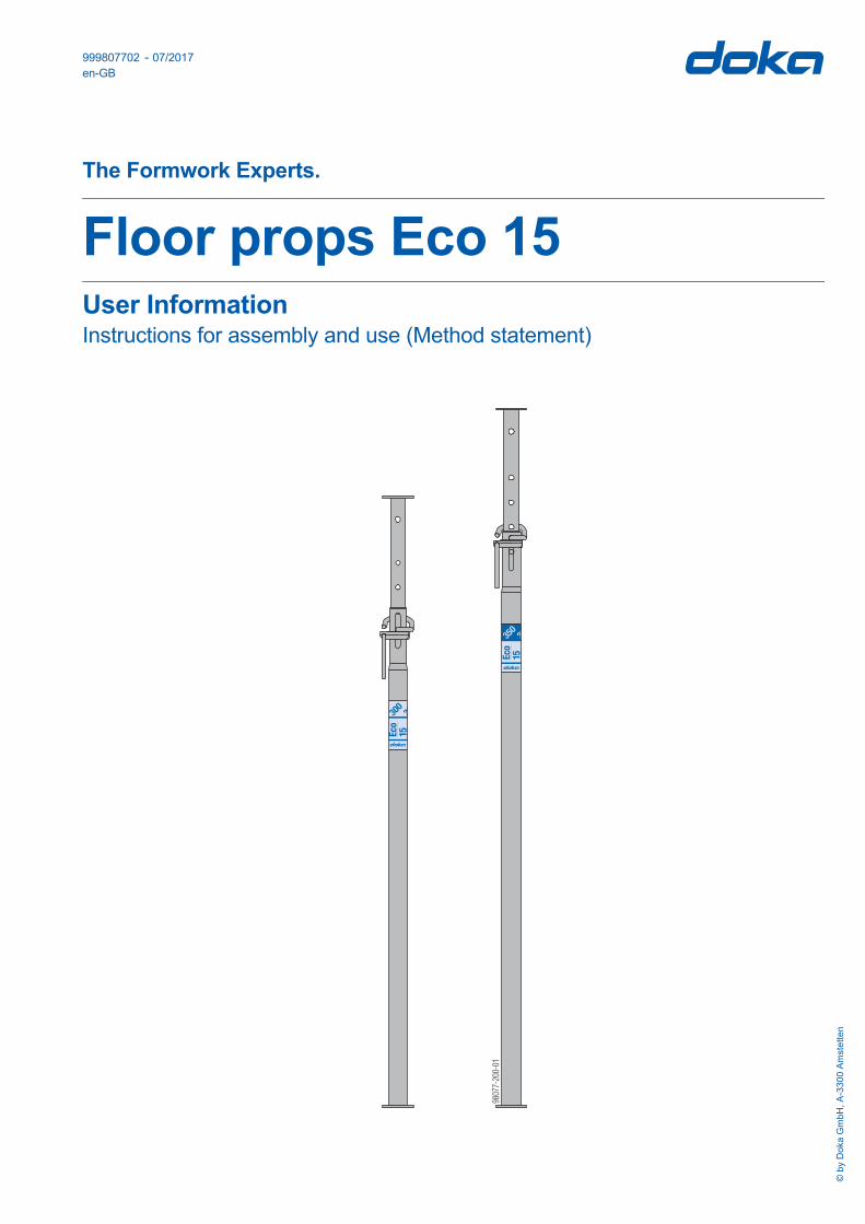
Floor props Eco 15User InformationInstructions for assembly and use (Method statement)© by Doka GmbH, A-3300 Amstetten
9
-2
0 -0
180
770

2 999807702 - 07/2017
User Information Floor props Eco 15
Elementary safety warnings
User target groups
▪ This booklet is aimed at all persons who will be work-ing with the Doka product or system that it describes. It contains information on the standard design for setting up this system, and on correct, compliant uti-lisation of the system.
▪ All persons working with the product described herein must be familiar with the contents of this booklet and with all the safety instructions it contains.
▪ Persons who are incapable of reading and under-standing this booklet, or who can do so only with dif-ficulty, must be instructed and trained by the cus-tomer.
▪ The customer is to ensure that the information mate-rials provided by Doka (e.g. User Information book-lets, Instructions for Assembly and Use, Operating Instruction manuals, plans etc.) are up to date and available to all users, and that they have been made aware of them and have easy access to them at the usage location.
▪ In the relevant technical documentation and form-work utilisation plans, Doka shows the workplace safety precautions that are necessary in order to use the Doka products safely in the usage situations shown. In all cases, users are obliged to ensure compliance with national laws, standards and regulations throughout the entire project and to take appropriate additional or alternative workplace safety precau-tions where necessary.
Hazard assessment
▪ The customer is responsible for drawing up, docu-menting, implementing and continually updating a hazard assessment at every job-site. This booklet serves as the basis for the site-specific hazard assessment, and for the instructions given to users on how to prepare and utilise the system. It does not substitute for these, however.
Remarks on this booklet
▪ This booklet can also be used as a generic method statement or incorporated with a site-specific method statement.
▪ Many of the illustrations in this booklet show the situation during formwork assembly and are therefore not always complete from the safety point of view.Any safety accessories not shown in these illustra-tions must still be used by the customer, in accord-ance with the applicable rules and regulations.
▪ Further safety instructions, especially warnings, will be found in the individual sections of this booklet!
Planning
▪ Provide safe workplaces for those using the form-work (e.g. for when it is being erected/dismantled, modified or repositioned etc). It must be possible to get to and from these workplaces via safe access routes!
▪ If you are considering any deviation from the details and instructions given in this booklet, or any application which goes beyond those described in the booklet, then revised static cal-culations must be produced for checking, as well as supplementary assembly instructions.
Regulations; industrial safety
▪ All laws, Standards, industrial safety regulations and other safety rules applying to the utilisation of our products in the country and/or region in which you are operating must be observed at all times.
▪ If a person or object falls against, or into, the side-guard component and/or any of its accessories, the component affected may only continue in use after it has been inspected and passed by an expert.

User Information Floor props Eco 15
3999807702 - 07/2017
Rules applying during all phases of the assignment
▪ Der Kunde muss sicherstellen, dass der Auf- und Abbau, das Umsetzen sowie die bestimmungs-gemäße Verwendung des Produktes gemäß den jeweils geltenden Gesetzen, Normen und Vorschrif-ten von fachlich geeigneten Personen geleitet und beaufsichtigt wird. Die Handlungsfähigkeit dieser Personen darf nicht durch Alkohol, Medikamente oder Drogen beein-trächtigt sein.
▪ Doka-Produkte sind technische Arbeitsmittel, die nur für gewerbliche Nutzung gemäß den jeweiligen Doka-Anwenderinformationen oder sonstigen von Doka verfassten technischen Dokumentationen zu gebrauchen sind.
▪ Die Standsicherheit und Tragfähigkeit sämtlicher Bauteile und Einheiten ist in jeder Bauphase sicher-zustellen!
▪ Auskragungen, Ausgleiche, etc. dürfen erst betreten werden, wenn entsprechende Maßnahmen zur Standsicherheit getroffen wurden (z.B.: durch Abspannungen).
▪ Die funktionstechnischen Anleitungen, Sicherheit-shinweise und Lastangaben sind genau zu beachten und einzuhalten. Die Nichteinhaltung kann Unfälle und schwere Gesundheitsschäden (Lebensgefahr) sowie erhebliche Sachschäden verursachen.
▪ Feuerquellen sind im Bereich der Schalung nicht zulässig. Heizgeräte sind nur bei sachkundiger Anwendung im entsprechenden Abstand zur Scha-lung erlaubt.
▪ Die Arbeiten sind an die Wetterbedingungen anzu-passen (z.B. Rutschgefahr). Bei extremen Wetter-bedingungen sind vorausschauende Maßnahmen zur Sicherung des Gerätes bzw. umliegender Bere-iche sowie zum Schutz der Arbeitnehmer zu treffen.
▪ Alle Verbindungen sind regelmäßig auf Sitz und Funktion zu überprüfen. Insbesondere sind Schraub- und Keilverbindungen, abhängig von den Bauabläufen und besonders nach außergewöhnlichen Ereignissen (z.B. nach Sturm), zu prüfen und gegebenenfalls nachzuziehen.
▪ Das Schweißen und Erhitzen von Doka-Produkten, insbesondere von Anker-, Aufhänge-, Verbindungs- und Gussteilen etc., ist strengstens verboten.Schweißen bewirkt bei den Werkstoffen dieser Bau-teile eine gravierende Gefügeveränderung. Diese führt zu einem dramatischen Bruchlastabfall, der ein hohes Sicherheitsrisiko darstellt.Das Ablängen von Ankerstäben mit Metalltrenn-scheiben ist zulässig (Wärmeeinbringung nur am Stabende), jedoch ist darauf zu achten, dass der Funkenflug keine anderen Ankerstäbe erhitzt und damit beschädigt.Es dürfen nur jene Artikel geschweißt werden, auf die in den Doka-Unterlagen ausdrücklich hingewi-esen wird.
Assembly
▪ The equipment/system must be inspected by the customer before use, to ensure that it is in suitable condition. Steps must be taken to rule out the use of any components that are damaged, deformed, or weakened due to wear, corrosion or rot.
▪ Combining our formwork systems with those of other manufacturers could be dangerous, risking damage to both health and property. If you intend to combine different systems, please contact Doka for advice first.
▪ The equipment/system must be assembled and erected in accordance with the applicable laws, Standards and rules by suitably skilled personnel of the customer's, having regard to any and all required safety inspections.
▪ It is not permitted to modify Doka products; any such modifications constitute a safety risk.
Closing the formwork
▪ Doka products and systems must be set up so that all loads acting upon them are safely transferred!
Pouring
▪ Do not exceed the permitted fresh-concrete pres-sures. Over-high pouring rates overload the form-work, cause greater deflection and risk breakage.
Stripping out the formwork
▪ Do not strip out the formwork until the concrete has reached sufficient strength and the person in charge has given the order for the formwork to be stripped out!
▪ When stripping out the formwork, never use the crane to break concrete cohesion. Use suitable tools such as timber wedges, special pry-bars or system features such as Framax stripping corners.
▪ When stripping out the formwork, do not endanger the stability of any part of the structure, or of any scaffolding, platforms or formwork that is still in place!

4 999807702 - 07/2017
User Information Floor props Eco 15
Transporting, stacking and storing
▪ Observe all regulations applying to the handling of formwork and scaffolding. In addition, the Doka slinging means must be used - this is a mandatory requirement.
▪ Remove any loose parts or fix them in place so that they cannot be dislodged or fall free!
▪ All components must be stored safely, following all the special Doka instructions given in the relevant sections of this booklet!
Maintenance
▪ Only original Doka components may be used as spare parts. Repairs may only be carried out by the manufacturer or authorised facilities.
Miscellaneous
The weights as stated are averages for new material; actual weights can differ, depending on material toler-ances. Dirt accretions, moisture saturation, etc. can also affect weight.We reserve the right to make alterations in the interests of technical progress.
Symbols used
The following symbols are used in this booklet:
NOTICEFailure to observe this may lead to malfunc-tion or damage.
CAUTION / WARNING / DANGERFailure to observe this may lead to material damage, and to injury to health which may range up to the severe or even life-threaten-ing.
InstructionThis symbol indicates that actions need to be taken by the user.
Sight-checkIndicates that you need to do a sight-check to make sure that necessary actions have been carried out.
TipPoints out useful practical tips.
ReferenceRefers to other documents and materials.

User Information Floor props Eco 15
5999807702 - 07/2017
Product descriptionDoka floor props Eco are extendable floor props made of steel. They are designed for use as vertical props for temporary structures.
The main features: ▪ High load-bearing capacity
- see the section headed 'Permitted carrying capacity'
▪ Quick connection: Head adapters of various types can be attached in a crane-handling-safe manner with the spring-locked connecting pin
▪ Drop-out latch: For safety reasons, Doka props have latches to pre-vent the inner tube sliding out of the outer tube.
▪ the special geometry of the thread, which makes the prop easier to release even when it is under high load
▪ When the prop is pushed in all the way, it still leaves a clear 10 cm gap so that the operator's hands are not trapped.
▪ galvanised, long-life constructional design
Practical examples
Dokaflex 15
Temporary reshores
A HeadplateB Inner tubeC Fastening clampD Adjusting nutE Toggle leverF Rating labelG Outer tubeH Baseplate
WARNING➤ It is not permitted to use the Floor prop
extension 0.50m.
A
B
CD
E
H
F
G
Follow the directions in the "Dokaflex 15" User Information booklet!
A Formwork sheetB Doka beam H20C Lowering head H20 or 4-way head H20
98060-201-01
9795-203-01
A
9795 3 3-20 -0
C
BB
6 999807702 - 07/2017
User Information Floor props Eco 15
Instructions for assembly and use (Method statement)
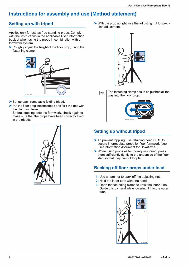
Setting up with tripod
Applies only for use as free-standing props. Comply with the instructions in the applicable User Information booklet when using the props in combination with a formwork system.➤Roughly adjust the height of the floor prop, using the
fastening clamp.
➤Set up each removable folding tripod.➤Put the floor prop into the tripod and fix it in place with
the clamping lever. Before stepping onto the formwork, check again to make sure that the props have been correctly fixed in the tripods.
➤With the prop upright, use the adjusting nut for preci-sion adjustment.
Setting up without tripod
➤To prevent toppling, use retaining head DF15 to secure intermediate props for floor formwork (see user information document for Dokaflex 15).
➤When using props as temporary reshoring, press them sufficiently tightly to the underside of the floor slab so that they cannot topple.
Backing off floor props under load
1) Use a hammer to back off the adjusting nut.2) Hold the inner tube with one hand.3) Open the fastening clamp to unfix the inner tube.
Guide this by hand while lowering it into the outer tube.
9720-006
9720-000
The fastening clamp has to be pushed all the way into the floor prop.
9720-006
98017-202-01
9720-006
1
2
3
User Information Floor props Eco 15
7999807702 - 07/2017
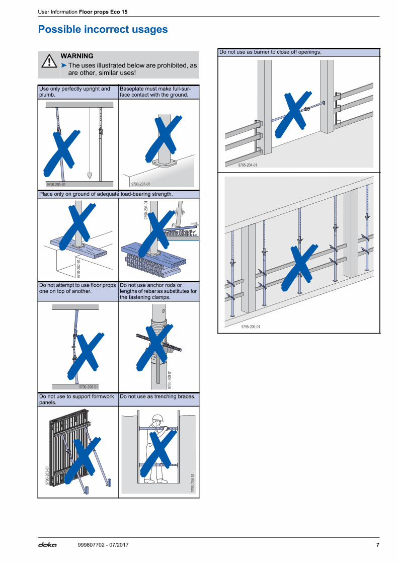
Possible incorrect usages
WARNING➤The uses illustrated below are prohibited, as
are other, similar uses!
Use only perfectly upright and plumb.
Baseplate must make full-sur-face contact with the ground.
Place only on ground of adequate load-bearing strength.
Do not attempt to use floor props one on top of another.
Do not use anchor rods or lengths of rebar as substitutes for the fastening clamps.
Do not use to support formwork panels.
Do not use as trenching braces.
9790-205-01 9790-207-01
9790
-202
-01
9790
-201
-01
9790-206-01 9790
-200
-01
9790
-203
-01
9790
-204
-01
Do not use as barrier to close off openings.
9795-204-01
9795-205-01

8 999807702 - 07/2017
User Information Floor props Eco 15
Technical conditionThe following quality criteria define the extent of dam-age permissible in terms of load-bearing strength. Use is prohibited if damage is beyond these limits.
Outer tube - inner tube
Head plate or baseplate bent out of shape
▪ a max. 1 mm outward and ▪ b max. 3 mm inward is permissible
Cracks in welds
▪ Not permissible.
Threads
▪ must be greased over entire length and action must be smooth.
Inner tube
▪ When the inner tube is rotated inside the outer tube so that the U-bolt fixing-holes of both tubes are lined up, it must be possible to fully extend and retract the inner tube.
Widening
▪ of the pegging holes in the inner tube is permissible up to 2 mm.
9790-208-07
b
a
9795-200-01 9795-200-01

User Information Floor props Eco 15
9999807702 - 07/2017
Permitted carrying capacity ▪ Permitted load-bearing capacity from tests in
accordance with US standards (ANSI) and as non-system-dependent construction prop: 15 kN
▪ Permitted load-bearing capacity as temporary reshores to British standards (BS): 22.5 kN
▪ Permitted load-bearing capacity [kN] as a function of extension length and position of the outer tube in accordance with the EN 1065 mathematical model:
*) Position of outer tube
Eco 15300 350
Prop
leng
th [m
]
at b
otto
m
at to
p
at b
otto
m
at to
p
Posi
tion
of
oute
r tub
e*)
3.5 10.5 12.53.2 12.5 15.73.0 10.1 12.3 13.3 18.22.8 11.4 14.5 13.9 21.12.6 12.0 16.8 14.8 22.52.4 12.4 19.3 17.3 22.52.2 14.0 21.1 20.5 22.52.0 16.6 21.4 22.5 22.51.9 19.1 21.41.7 21.4 21.4
at bottom at top
Article n°[kg] Article n°[kg]
10 999807702 - 07/2017
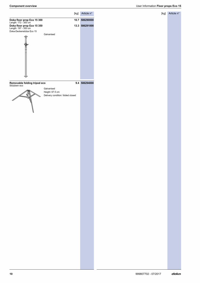
Component overview User Information Floor props Eco 15
Component overview[kg]Article n°
Doka floor prop Eco 15 300 10.7 586290000Length: 172 - 300 cmDoka floor prop Eco 15 350 13.3 586291000Length: 197 - 350 cmDoka-Deckenstütze Eco 15
Removable folding tripod eco 9.4 586294000Stützbein eco
Galvanised
GalvanisedHeight: 67.5 cmDelivery condition: folded closed

User Information Floor props Eco 15 Component overview
11999807702 - 07/2017

999807702 - 07/2017Doka GmbH | Josef Umdasch Platz 1 | 3300 Amstetten | Austria | T +43 7472 605-0 | F +43 7472 66430 | [email protected] | www.doka.com
Near to you, worldwide
Doka is one of the world leaders in developing, manu-facturing and distributing formwork technology for use in all fields of the construction sector.With more than 160 sales and logistics facilities in over 70 countries, the Doka Group has a highly efficient dis-tribution network which ensures that equipment and
technical support are provided swiftly and profession-ally.An enterprise forming part of the Umdasch Group, the Doka Group employs a worldwide workforce of more than 6000.
www.doka.com/floor-props