the evolution of mobile mapping - gis-t symposium · the evolution of mobile mapping presented...
TRANSCRIPT
The Evolution of Mobile MappingThe Evolution of Mobile MappingPresented Presented by: by: Allen Ibaugh, AICP, GISPAllen Ibaugh, AICP, GISP

Where it all began…

Where we are Today…

The Technology…
Aerial LiDAR Aerial photographyMobile LiDAR
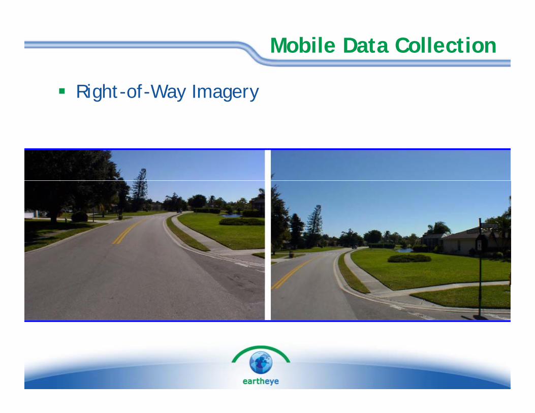
Mobile Data Collection
Right-of-Way Imagery

Mobile Data Collection
Pavement Imagery

Mobile Data Collection
Mobile LiDAR Terrain Modeling
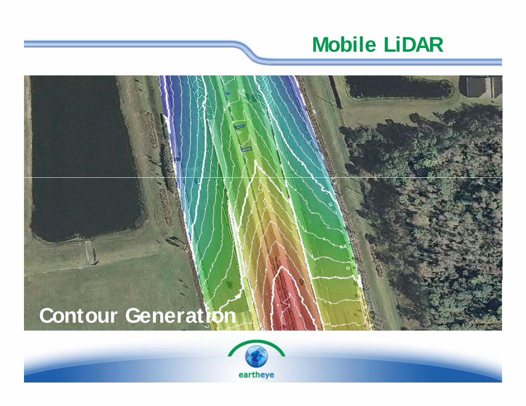
Mobile LiDAR
Contour Generation
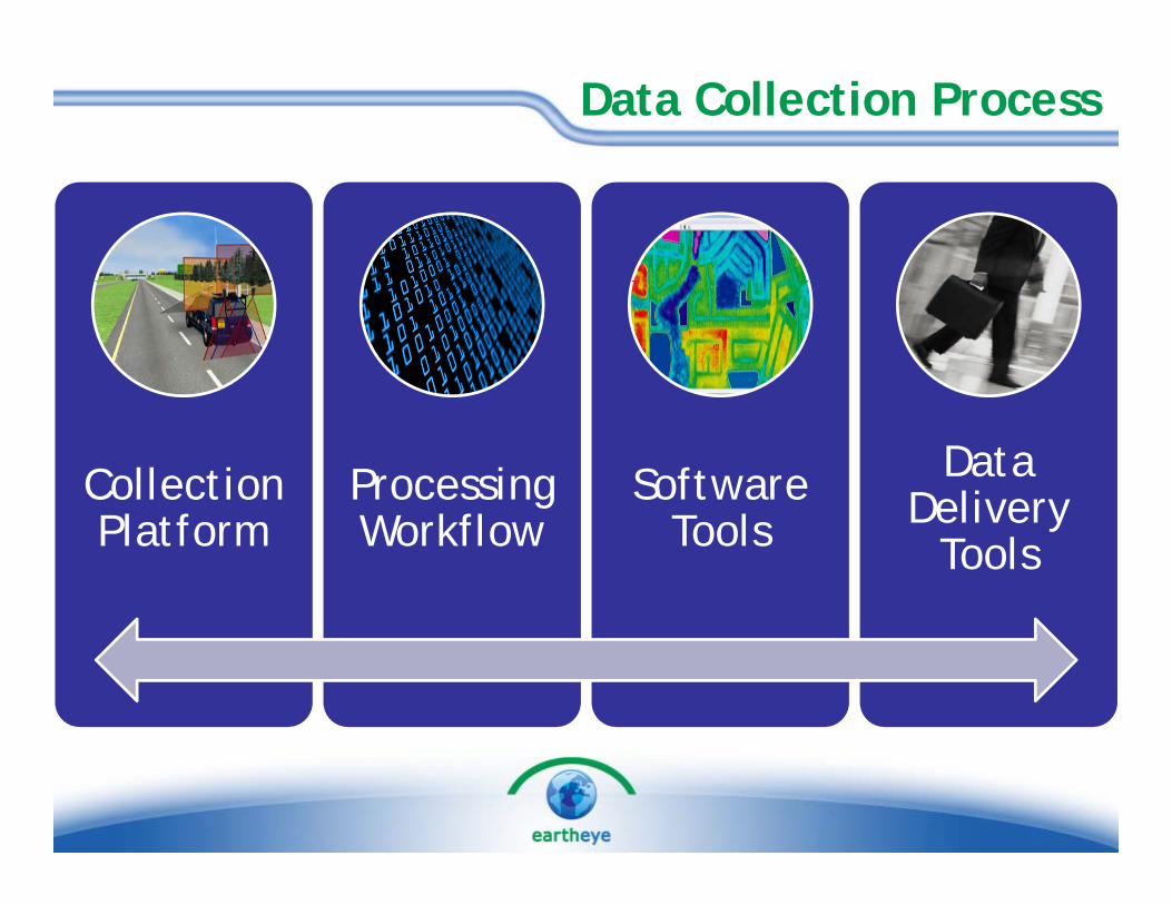
Data Collection Process
Collection Processing Software Data Delivery Platform Workflow Tools Delivery
Tools

Collection Platform
M bil A C ll i V hi l• Mobile Asset Collection Vehicle
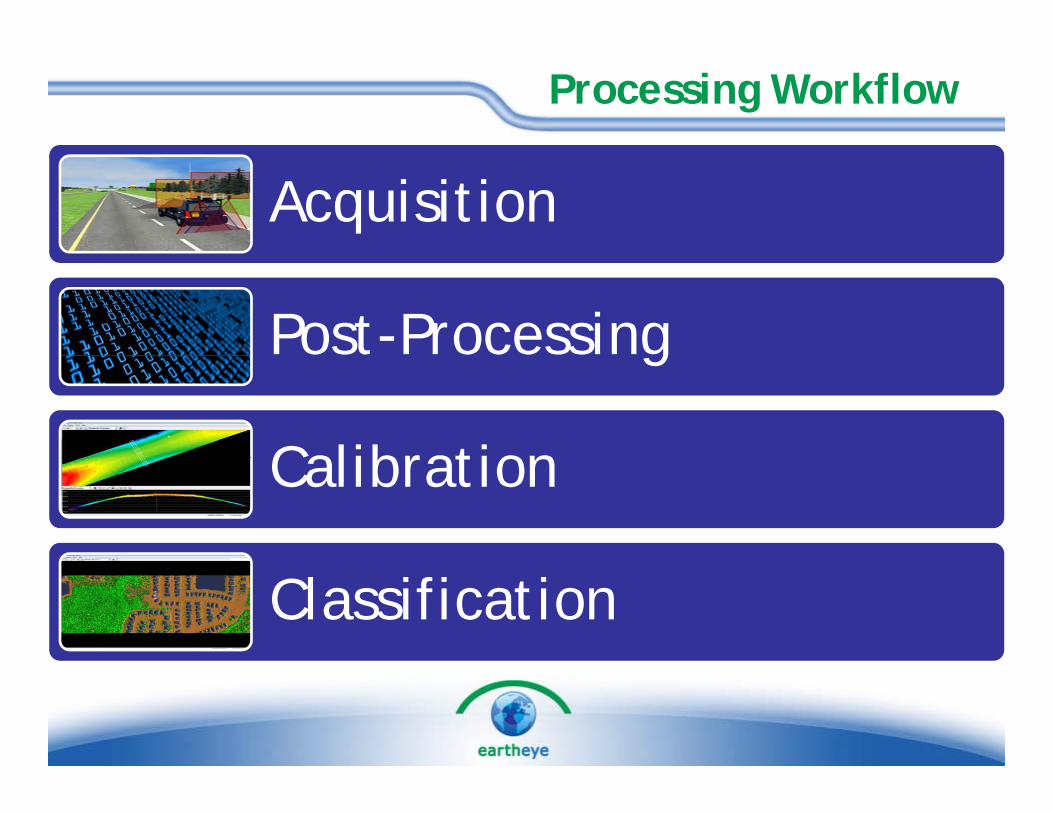
Processing Workflow
Acquisition
Post-Processingg
CalibrationCalibration
Classification
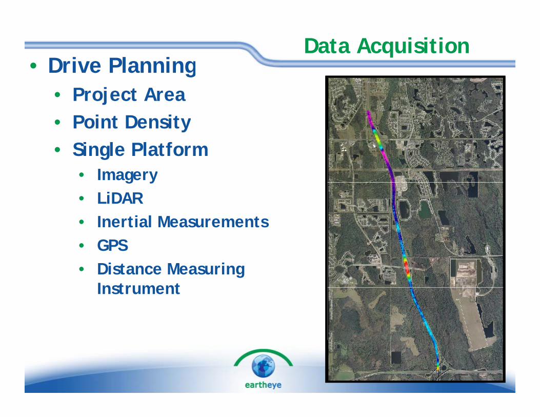
Data Acquisition• Drive Planningg
• Project Area• Point Densityy• Single Platform
• Imageryg y• LiDAR• Inertial Measurements• GPS• Distance Measuring
InstrumentInstrument

Post-Processing
B S i• Base Stations• 2 Trimble RTK-Capable Rovers• Maintain short baselines for better Maintain short baselines for better
accuracies• GLONASS-capable receivers
I ti l S l ti• Inertial Solution• Integrated with LiDAR
• Ground Control• Ground Control• Typically used for accuracy
assessment l 20 f 9 % • At least 20 points to satisfy 95%
confidence level

Data Calibration
U lib t d D t 0 4 ft di b t d i li• Uncalibrated Data – 0.4 ft discrepancy between drive lines

Data Calibration
C lib t d D t 0 1 ft di b t d i li• Calibrated Data – <0.1 ft discrepancy between drive lines

Data Classification
U l ifi d D• Unclassified Data• All points are positionally
correct but they don’t know correct, but they don t know “What” they are…
• Need to be assigned to a “Class” of data
• Typical Classes are listed to the rightthe right…
• Classification allows for modeling and analysis of the point cloud.
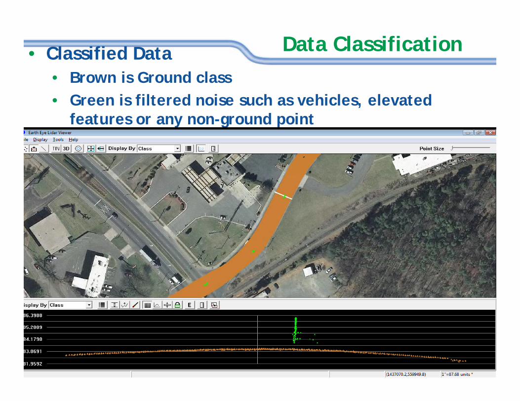
Data Classification• Classified DataB i G d l• Brown is Ground class
• Green is filtered noise such as vehicles, elevated features or any non-ground pointy g p
Case Study Case Study –– SR417 Mobile LiDARSR417 Mobile LiDARCase Study Case Study SR417 Mobile LiDARSR417 Mobile LiDAR
Data Collection ProjectData Collection Project

Project PresentationProject PresentationIntentIntent
Investigate the effectiveness of Mobile Data Collection vs. Investigate the effectiveness of Mobile Data Collection vs. LowLow--Altitude Mapping and Photography (LAMP) and Altitude Mapping and Photography (LAMP) and Traditional SurveyingTraditional SurveyingTraditional SurveyingTraditional SurveyingImprove Safety for Field Crews and Limit Traffic Improve Safety for Field Crews and Limit Traffic InterruptionsInterruptions
RequirementsRequirementsMobile Scan of Entire Paved Surface, including on and offMobile Scan of Entire Paved Surface, including on and off--rampsramps0.050.05--foot relative accuracy (15mm)foot relative accuracy (15mm)Assessment of Absolute AccuracyAssessment of Absolute AccuracyAssessment of Absolute AccuracyAssessment of Absolute AccuracyDigital Terrain Model (DTM) and 3D Breaklines Digital Terrain Model (DTM) and 3D Breaklines Certification by Independent Survey and Mapping CompanyCertification by Independent Survey and Mapping CompanyCertification by Independent Survey and Mapping CompanyCertification by Independent Survey and Mapping Company

Site
Project PresentationProject PresentationSite
Orlando, Florida4 C t li Mil T ll Hi h (i l di 4 Centerline Mile Toll Highway (including interchanges)2 3 Lanes on Main thoroughfare2-3 Lanes on Main thoroughfare2-5 lanes on Toll plaza and On / Exit RampsHi h S t i b i li d d Highway Segment is being re-aligned and re-habilitated

Project PresentationProject Presentation
AlternativesLow-Altitude Mapping and Photogrammetry (LAMP)Traditional Surveying
Benefits of Mobile PlatformEfficiencySafetyLiDARLiDARCost-EffectiveShort TurnaroundShort Turnaround
Field ProcedureField Procedure
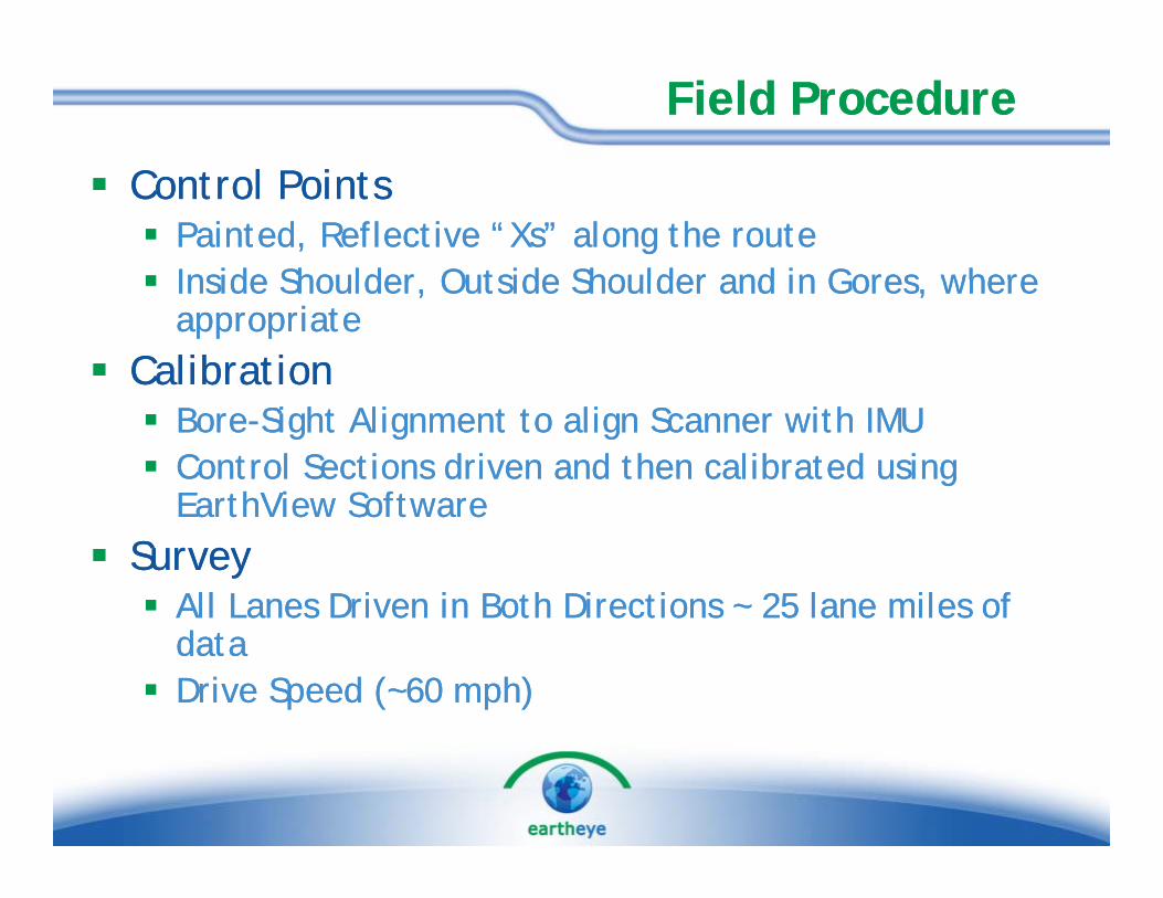
Control PointsControl PointsPainted, Reflective “Xs” along the routePainted, Reflective “Xs” along the routeInside Shoulder Outside Shoulder and in Gores where Inside Shoulder Outside Shoulder and in Gores where Inside Shoulder, Outside Shoulder and in Gores, where Inside Shoulder, Outside Shoulder and in Gores, where appropriateappropriate
CalibrationCalibrationBoreBore--Sight Alignment to align Scanner with IMUSight Alignment to align Scanner with IMUControl Sections driven and then calibrated using Control Sections driven and then calibrated using EarthView SoftwareEarthView SoftwareEarthView SoftwareEarthView Software
SurveySurveyAll Lanes Driven in Both Directions ~ 25 lane miles of All Lanes Driven in Both Directions ~ 25 lane miles of datadataDrive Speed (~60 mph)Drive Speed (~60 mph)


Control ValidationControl ValidationControl PointsControl Points
Used to validate horizontal and vertical accuracy (they Used to validate horizontal and vertical accuracy (they are apparent in the point cloud)are apparent in the point cloud)
Used for tieUsed for tie--in adjustments (if necessary, depending on in adjustments (if necessary, depending on business requirements)business requirements)business requirements)business requirements)

TargetTarget StencilStencil
Size important in order to be observed on raw LiDAR
l dpoint CloudSize dependent on LiDAR sensor type and collection ypspeed of vehicleCenter of Target Surveyed by traditional methodsby traditional methodsSurveyed Corners / Ends of Target beneficial but not a mustmust


R LiDAR i t l d t d t ti llR LiDAR i t l d t d t ti ll
Data CollectionData Collection
•• Raw LiDAR points clouds created automaticallyRaw LiDAR points clouds created automatically•• Accuracy relates directly to GPS post processing of Accuracy relates directly to GPS post processing of
vehicle trace at 100 Hzvehicle trace at 100 Hz•• No significant processing required to generate raw No significant processing required to generate raw
point clouds. Automation is the key!point clouds. Automation is the key!
C ti f DTM i t t d
DTM CreationDTM Creation
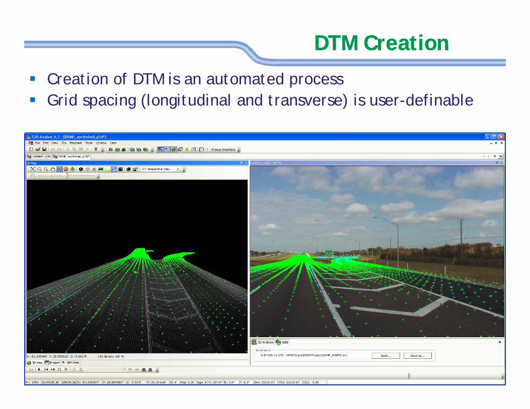
Creation of DTM is an automated processGrid spacing (longitudinal and transverse) is user-definable
E h g id i t b i gl h t g f t f E h g id i t b i gl h t g f t f
DTM CreationDTM Creation
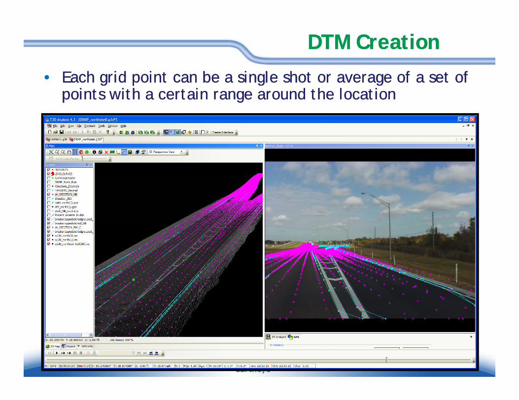
•• Each grid point can be a single shot or average of a set of Each grid point can be a single shot or average of a set of points with a certain range around the locationpoints with a certain range around the location

DTM CreationDTM Creation
Each grid point can be a single shot or average of a set of Each grid point can be a single shot or average of a set of points with a certain range around the locationpoints with a certain range around the location
Single DTM point Single DTM point created by ~ 20 raw LiDAR shots

3D Breakline Creation3D Breakline Creation
BreaklinesBreaklines are a common requirement in DTM / TIN modelingare a common requirement in DTM / TIN modelingUsually represent pavement markings / edge of pavementUsually represent pavement markings / edge of pavementBreaklines Breaklines digitized using point cloud intensitydigitized using point cloud intensityBreaklines Breaklines digitized using point cloud intensitydigitized using point cloud intensity
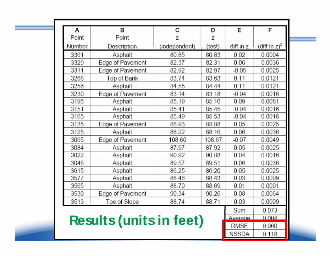
Results (units in feet)Results (units in feet)
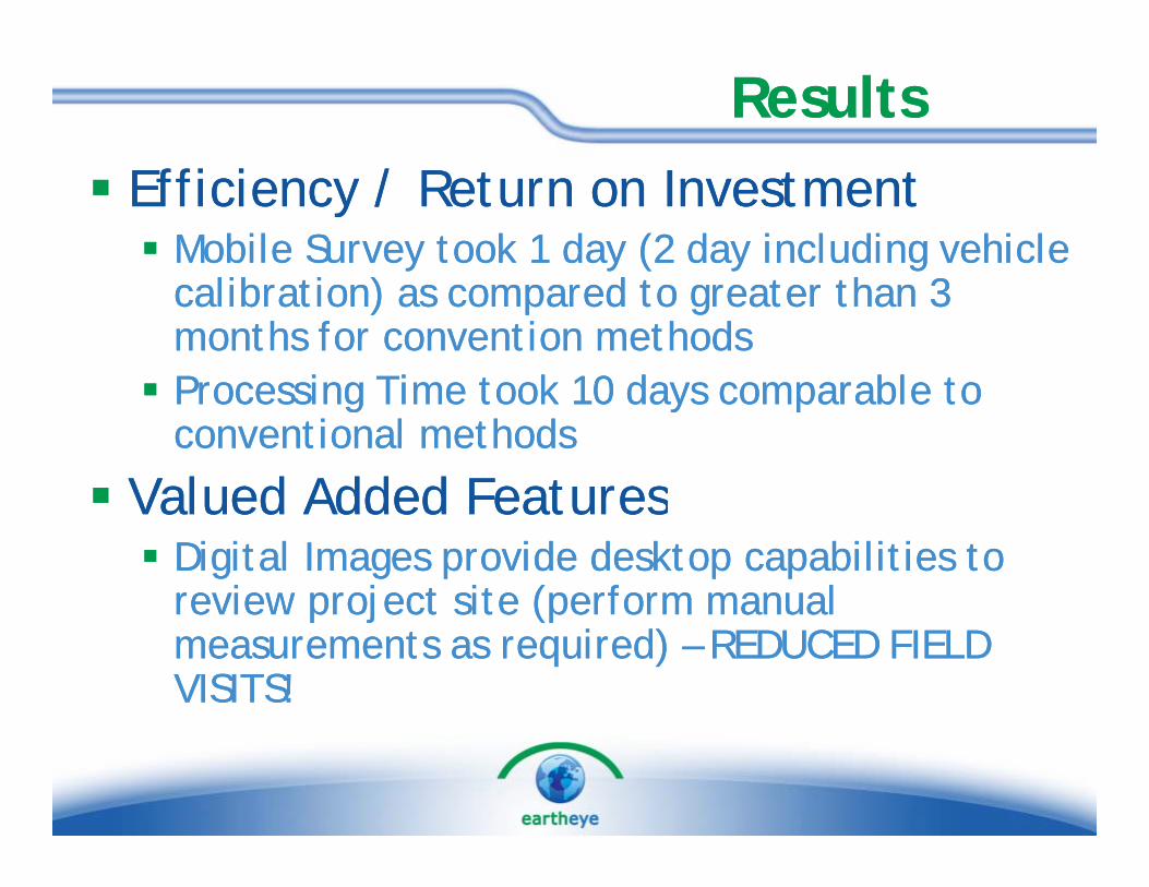
ResultsResultsEfficiency / Return on InvestmentEfficiency / Return on Investment
Mobile Survey took 1 day (2 day including vehicle Mobile Survey took 1 day (2 day including vehicle calibration) as compared to greater than 3 calibration) as compared to greater than 3 months for convention methodsmonths for convention methodsProcessing Time took 10 days comparable to Processing Time took 10 days comparable to Processing Time took 10 days comparable to Processing Time took 10 days comparable to conventional methodsconventional methods
Valued Added FeaturesValued Added FeaturesValued Added FeaturesValued Added FeaturesDigital Images provide desktop capabilities to Digital Images provide desktop capabilities to review project site (perform manual review project site (perform manual review project site (perform manual review project site (perform manual measurements as required) measurements as required) –– REDUCED FIELD REDUCED FIELD VISITS!VISITS!
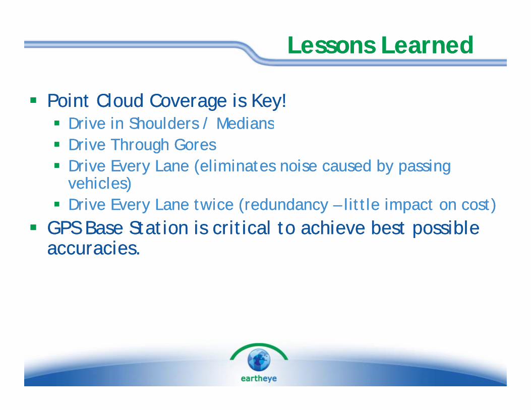
Lessons LearnedLessons Learned
Point Cloud Coverage is Key!Point Cloud Coverage is Key!Drive in Shoulders / MediansDrive in Shoulders / MediansDrive in Shoulders / MediansDrive in Shoulders / MediansDrive Through GoresDrive Through GoresDrive Every Lane (eliminates noise caused by passing Drive Every Lane (eliminates noise caused by passing
hi l )hi l )vehicles)vehicles)Drive Every Lane twice (redundancy Drive Every Lane twice (redundancy –– little impact on cost)little impact on cost)
GPS Base Station is critical to achieve best possible GPS Base Station is critical to achieve best possible GPS Base Station is critical to achieve best possible GPS Base Station is critical to achieve best possible accuracies.accuracies.

A d Si D i i iDAR
Sign Detection
Automated Sign Detection using LiDARSign locations are analyzed through comparison to sign librarySemi-automated (due to non-standard signs)Sign compiler available

Asset Images are Linked to Asset Images are Linked to GIS using ArcGIS Server