the evolution and appication of three- dimensional stress ... · appication of three-dimensional...
TRANSCRIPT

THETHE EVOLUTIONEVOLUTION ANDAND APPICATIONAPPICATION OFOF THREETHREE--DIMENSIONALDIMENSIONAL STRESSSTRESS--INTENSITYINTENSITY FACTORSFACTORS
J. C. Newman, Jr.Mississippi State University
Starkville, MS
I. S. RajuNASA Langley Research Center
Hampton, VA
S. A. FawazU. S. Air Force Academy
Colorado Springs, CO
The George R. Irwin Centennial ConferenceUniversity of Maryland
18-20 March 2007College Park, MD

Irwin 100th Conference - # 2
George Rankin IrwinGeorge Rankin Irwin
Irwin 100th Conference - # 3
OUTLINE OF PRESENTATIONOUTLINE OF PRESENTATION
• Embedded Elliptical Crack
• Methods of Solution for Finite-Body Problems
• The Surface-Crack Problem• The Boundary-Layer Effect• Surface and Corner Crack(s) at a Hole• Application to Fatigue-Crack Growth• Application to Fracture• Concluding Remarks

Irwin 100th Conference - # 4
EMBEDDED ELLIPTICAL CRACK TO ANEMBEDDED ELLIPTICAL CRACK TO ANAPPROXIMATE SURFACE CRACK SOLUTIONAPPROXIMATE SURFACE CRACK SOLUTION
πGreen & Sneddon (1950) Irwin (1962)
fφ

Irwin 100th Conference - # 5
METHODS OF SOLUTION FOR FINITEMETHODS OF SOLUTION FOR FINITE--BODY PROBLEMSBODY PROBLEMS
• Engineering Estimates • Alternating Methods• Line-Spring Model• Boundary-Element Methods• Finite-Element Methods
COD methodsJ-Integral or energy methodsNodal-force method

Irwin 100th Conference - # 6
THE SURFACETHE SURFACE--CRACK PROBLEMCRACK PROBLEM
2w

Irwin 100th Conference - # 7
SEMISEMI--CIRCULAR SURFACE CRACK UNDER CIRCULAR SURFACE CRACK UNDER REMOTE TENSIONREMOTE TENSION
a / t0.0 0.2 0.4 0.6 0.8 1.0
0.9
1.0
1.1
1.2
1.3
1.4
Irwin
Anderson-Holms-Orange
Paris-Sih
Raju-Newman
KobayashiSmith
Shah-Kobayashi
Kobayashi-Moss
Newman
Hellen-Blackburn
Newman-Raju
a / c = 1φ = π / 2
K
S √πa/Q
Newman (1979)

Irwin 100th Conference - # 8
SEMISEMI--ELLIPTICAL SURFACE CRACK UNDERELLIPTICAL SURFACE CRACK UNDERREMOTE TENSIONREMOTE TENSION
a / t0.0 0.2 0.4 0.6 0.8 1.0
0.8
1.0
1.2
1.4
1.6
1.8
2.0
2.2
2.4Newman
Smith
Raju-Newman
Rice-Levy
Masters et.al
Kobayashi
IrwinParis-Sih
Anderson et.al
Shah-Kobayashi
Kobayashi-Moss
Smith-Sorensen
Newman-Rajua / c = 0.2φ = π / 2
K
S √πa/Q
Newman (1979)

Irwin 100th Conference - # 9
THE BOUNDARYTHE BOUNDARY--LAYER EFFECTLAYER EFFECT
Lose of square-root singularity Free surface
Hartranft & Sih (1970)Benthem & Koiter (1973)
Crack

Irwin 100th Conference - # 10
EFFECT OF FE MESH REFINEMENT ON EFFECT OF FE MESH REFINEMENT ON NORMALIZED STRESSNORMALIZED STRESS--INTENSITY FACTORSINTENSITY FACTORS
2 φ / π0.0 0.2 0.4 0.6 0.8 1.0
1.00
1.05
1.10
1.15
1.20
8 Wedge model10 Wedge model14 Wedge model
Semi-circular crack:a / c = 1a / t = 0.2
K
S √πa/Q
Estimatedboundaylayer
Raju & Newman (1979)

Irwin 100th Conference - # 11
CRACK CONFIGURATIONS ANALYZED WITH FEACRACK CONFIGURATIONS ANALYZED WITH FEAUNDER REMOTE TENSION OR BENDING LOADSUNDER REMOTE TENSION OR BENDING LOADS
2r
2r
w
2w
2w2w
2w
Raju & Newman (1979-1986)

Irwin 100th Conference - # 12
SURFACE CRACK AT A HOLE UNDER TENSION SURFACE CRACK AT A HOLE UNDER TENSION
0.0 0.2 0.4 0.6 0.8 1.00.0
0.5
1.0
1.5
2.0
2.5
3.0
K
S √πa/Q
2 φ / π
a / c = 1
a / c = 0.2
Shah
Raju-Newman
Raju-Newman
Shah
Newman-Raju Equation
r / t = 1a / t = 0.5
Newman & Raju (1981)
K = S (πa/Q)1/2 F(φ, a/c, a/ t, c/ r, c/ w)

Irwin 100th Conference - # 13
ILLILL--SHAPED ELEMENT MESH PROBLEM SHAPED ELEMENT MESH PROBLEM CORNER CRACK AT A HOLE UNDER TENSION CORNER CRACK AT A HOLE UNDER TENSION
φ, degrees
0 30 60 900.0
0.5
1.0
1.5
2.0
2.5
3.0
3.5
Model A (ill-shaped elements)Model B (new mesh)
Model C
Newman-Raju Equation
Force Method:
VCCT Method:
K
S √πa/Q
r / t = 1a / c = 1a / t = 0.2
Tan et al (1988)

Irwin 100th Conference - # 14
STRESSSTRESS--INTENSITY FACTORS FOR QUARTERINTENSITY FACTORS FOR QUARTER--ELLIPTICELLIPTICCORNER CRACKSCORNER CRACKS
Parametric angle, φ , degrees
0 30 60 902.0
2.5
3.0
3.5
BEM
Equation(Newman-Raju)
WFM(3D)FEM(DIM)
Plate surface Hole surface
FADD(3D)
FEAM
FEM(GIL,J)
5%
r/t = 2; r/w = 0.2a/c = 0.8; a/t = 0.2
K
S √πa/Q
Bakuckas (1999)

Irwin 100th Conference - # 15
CORNER CRACK(S) AT AN OPENCORNER CRACK(S) AT AN OPEN--HOLE UNDER REMOTEHOLE UNDER REMOTETENSION AND BENDING LOADSTENSION AND BENDING LOADS
• Raju and Newman (1979-86)FEA (h-version)~10,000 dof (0.5 < r / t < 2)
• Fawaz and Andersson (2000-04)FEA (p-version)100,000+ dof (0.1 < r / t < 10)
K = S (πa/Q)1/2 F(φ, a/c, a/ t, c/ r, c/ w)
2w

Irwin 100th Conference - # 16
Fawaz & Andersson Crack Configurations Analyzed and Fawaz & Andersson Crack Configurations Analyzed and SelectedSelected Values for Tension and Bending EvaluationsValues for Tension and Bending Evaluations
Hole-radius-to-plate-thickness (r/ t) ratio:0.1, 0.111, 0.125, 0.143, 0.166, 0.2, 0.25, 0.333,0.5, 0.666, 0.75, 0.8, 1.0, 1.25, 1.333, 1.5, 1.666,2.0, 3.0, 4.0, 5.0, 6.0, 7.0, 8.0, 9.0, 10.0
Crack-depth-to-crack-length (a/c) ratio:0.1, 0.111, 0.125, 0.143, 0.166, 0.2, 0.25, 0.333, (0.4),0.5, 0.666, 0.75, 1.0, 1.333, 1.5, 2.0, 3.0, 4.0, 5.0, 6.0, 7.0, 8.0, 9.0, 10.0
Crack-depth-to-plate-thickness (a/ t) ratio:0.1, 0.2, 0.3, 0.4, 0.5, 0.6, 0.7, 0.8, 0.9, 0.95, 0.99
Note: a/ t < 0.1 needs further FE analyses (like a/ t = 0.01 & 0.05)Red: Considered by Raju & Newman

Irwin 100th Conference - # 17
Corner Crack at Hole under Tension: a/c = 1 and Corner Crack at Hole under Tension: a/c = 1 and φφ = 0 & 90= 0 & 90oo
a / t0.0 0.2 0.4 0.6 0.8 1.0
F(0)or
F(90)
0
1
2
3
4
5
NR φ = 0 NR φ = 90 degFA φ = 0 FA φ = 90 deg
Corner crack at hole - Tensionr / t = 1 and a / c = 1 Major
discovery
w = 6 r
w = 400 r
}
}

Irwin 100th Conference - # 18
Corner Crack at Hole under Bending: a/c = 1 and Corner Crack at Hole under Bending: a/c = 1 and φφ = 0 & 90= 0 & 90oo
a / t0.0 0.2 0.4 0.6 0.8 1.0
F(0)or
F(90)
-2
-1
0
1
2
3
NR φ = 0 NR φ = 90 degFA φ = 0 FA φ = 90 deg
Corner crack at hole - Bendingr / t = 1 and a / c = 1
Majordiscovery
w = 6 r
w = 400 r
}
}

Irwin 100th Conference - # 19
Corner Crack at Hole under Tension: a/c = 0.25 and a/t = 0.1 Corner Crack at Hole under Tension: a/c = 0.25 and a/t = 0.1
2φ / π0.0 0.2 0.4 0.6 0.8 1.0
Ft
0
1
2
3
4
5
0.1250.51.02.08.0
Corner cracks at hole - Tensionr / w = 0; a / c = 0.25; a / t = 0.1Fawaz and Andersson (2000) r / t
Newman and Raju (1986)NRFA Equations

Irwin 100th Conference - # 20
Corner Crack at Hole under Tension: a/c = 0.5 and a/t = 0.1 Corner Crack at Hole under Tension: a/c = 0.5 and a/t = 0.1
2φ / π0.0 0.2 0.4 0.6 0.8 1.0
Ft
0
1
2
3
4
5
0.1250.51.02.08.0
Corner cracks at hole - Tensionr /Fawaz and Andersson (2000) r / t
Newman and Raju (1986)NRFA Equations
w = 0; a / c = 0.5; a / t = 0.1

Irwin 100th Conference - # 21
Corner Crack at Hole under Tension: a/c = 1.0 and a/t = 0.5 Corner Crack at Hole under Tension: a/c = 1.0 and a/t = 0.5
2φ / π0.0 0.2 0.4 0.6 0.8 1.0
Ft
0
1
2
3
4
5
6
0.1250.51.02.08.0
Corner cracks at hole - Tensionr / w = 0; a / c = 1.0; a / t = 0.5
Fawaz and Andersson (2000) r / t
NRFA EquationsNewman and Raju (1986)

Irwin 100th Conference - # 22
Corner Crack at Hole under Tension: a/c = 1.0 and a/t = 0.95 Corner Crack at Hole under Tension: a/c = 1.0 and a/t = 0.95
2φ / π0.0 0.2 0.4 0.6 0.8 1.0
Ft
0
1
2
3
4
5
6
0.1250.51.02.08.0
Corner cracks at hole - Tensionr / w = 0; a / c = 1.0; a / t = 0.95
Fawaz and Andersson (2000)
Newman and Raju (1986)NRFA Equations
r / t

Irwin 100th Conference - # 23
Corner Crack at Hole under Tension: a/c = 4 and a/t = 0.95 Corner Crack at Hole under Tension: a/c = 4 and a/t = 0.95
2φ / π0.0 0.2 0.4 0.6 0.8 1.0
Ft
0.0
0.5
1.0
1.5
2.0
2.5
3.0
0.1250.51.02.08.0
Corner cracks at hole - Tensionr / w = 0; a / c = 4.0; a / t = 0.95
Fawaz and Andersson (2000) r / t
Newman and Raju (1986)NRFA Equations

Irwin 100th Conference - # 24
APPLICATION TO FATIGUEAPPLICATION TO FATIGUE--CRACK GROWTH CRACK GROWTH
Plane-stress behavior Free surface
Jolles & Tortoriello (1983)Newman & Raju (1984)
Plane-strain behavior
Crack

Irwin 100th Conference - # 25
PLANEPLANE--STRESSSTRESS--TOTO--PLANEPLANE--STRAIN CONVERSIONSTRAIN CONVERSION
Stress ratio, R0.0 0.2 0.4 0.6 0.8 1.0
βR
0.0
0.2
0.4
0.6
0.8
1.0
1.2Jolles & Tortoriello (1983)
βR = 0.9 + 0.2 R2 - 0.1 R4
βRβR
Newman & Raju (1984)
∆Kfs = βR ∆K
Irwin 100th Conference - # 26
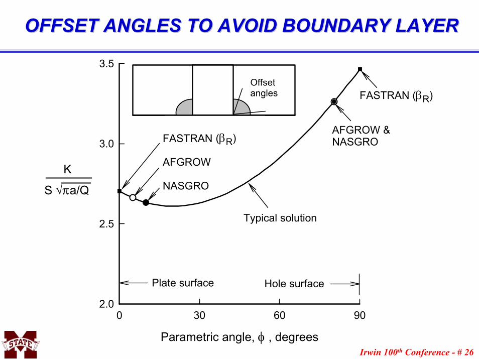
OFFSET ANGLES TO AVOID BOUNDARY LAYER OFFSET ANGLES TO AVOID BOUNDARY LAYER
Parametric angle, φ , degrees
0 30 60 902.0
2.5
3.0
3.5
Plate surface Hole surface
K
S √πa/Q
FASTRAN
AFGROW
NASGRO
FASTRAN (βR)
AFGROW &NASGRO(βR)
Typical solution
Offset angles

Irwin 100th Conference - # 27
PREDICTION OF SURFACEPREDICTION OF SURFACE--CRACKCRACK--ATAT--HOLE SHAPE HOLE SHAPE AND CRACKAND CRACK--GROWTH BEHAVIORGROWTH BEHAVIOR
N x 10-3, cycles
0 5 10 15 20 25
a , cmm
0
1
2
3
4
5
6
7 McGee & Hsu (1981) 7075-T651 t = 6.3 mm r = 4 mm R = 0.1
Test (a)
Predicted
Test (c)
a / t0.0 0.2 0.4 0.6 0.8 1.0
a / c
0.0
0.5
1.0
1.5
2.0
2.5
McGee & Hsu (1981) 7075-T651 t = 6.3 mm r = 4 mm R = 0.1
Test
Predicted
2r

Irwin 100th Conference - # 28
APPLICATION TO FRACTUREAPPLICATION TO FRACTURE(Surface crack in D6ac steel under bending loads) (Surface crack in D6ac steel under bending loads)
Parametric angle, φ, deg.
0 30 60 90
Parameters (αh, Fb, Fb αh)
0.0
0.5
1.0
1.5
2.0
2.5
Fb
αh
Fb αh
D6ac steela / c = 0.86a / t = 0.72c / w = 0.1Sb / σo = 0.87
Critical location (φc = 14.4 deg.)
Test range

Irwin 100th Conference - # 29
FRACTURE OF SURFACE AND THROUGH CRACKS FRACTURE OF SURFACE AND THROUGH CRACKS
Constraint, αh
1.0 1.5 2.0 2.5 3.0
(Kφ)Ic
0
20
40
60
80
100
+20%
-20%
(Kφ)Ic αh = 140 MPa-m1/2
Three-point bend
D6AC steel (Reuter and Panontin):Surface crack - tensionSurface crack - bending

Irwin 100th Conference - # 30
CONCLUDING REMARKSCONCLUDING REMARKS
1. Advancements in computers and highly-refined finite-element models have been used to develop more accurate stress-intensity factors for three-dimensional crack configurations – but more analyses and improved equations are needed over a wide range of loading and crack configuration parameters (such as very shallow and very deep cracks).
2. The Newman-Raju equations have been found to be fairly accurate over a wide range in crack configurations, but the new Fawaz-Anderssonfinite-element solutions for a corner-crack-at-a-hole under remote tension or bending loads have resulted in more accurate equations.
3. Three-dimensional stress-intensity factor solutions have improved the fatigue-crack growth predictions for complex crack configurations.
4. Three-dimensional stress-intensity factor solutions and local crack-front constraint variations have allowed the correlation of fracture for surface and through cracks under both tension and bending loads.
Thank you, Dr. Irwin …Thank you, Dr. Irwin …