the espresso assembly instructions · zeppelindesignlabs.com • 2950 n. western, chicago, il 60618...
TRANSCRIPT

ZEPPELINDESIGNLABS.COM • 2950 N. WESTERN, CHICAGO, IL 60618
PHANTOM POWER SUPPLY
Assembly Instructions thE ESPRESSO

2
THE ESPRESSOPortable Phantom Power Supply
© 2016 ZEPPELIN DESIGN LABS. NO PART OF THIS DOCUMENT MAY BE REPRODUCED WITHOUT WRITTEN PERMISSION FROM THE AUTHOR. ZEPPELIN DESIGN LABS TAKES NO RESPONSIBILITY FOR ANY DAMAGE OR HARM THAT MAY COME TO ANYONE OR
ANYTHING THROUGH THEIR PRODUCTS.
INTRODUCTION ...................................................................................................... 3
WHAT YOU WILL NEED ............................................................................................ 4
WHAT’S IN THE BOX ............................................................................................... 5
POPULATING THE PRINTED CIRCUIT BOARD ............................................................... 7
MODIFYING THE POWER SUPPLY MODULE .............................................................. 18
XLR JACK ............................................................................................................... 21
THE CONTAINER .................................................................................................... 24
PUTTING IT ALL TOGETHER ..................................................................................... 27
TESTING ................................................................................................................ 32
CONTAINER TEMPLATE ........................................................................................... 34

3
INTRODUCTIONPhantom Power is an ingenious method for powering condenser microphones and other audio devices with active electronics circuits. A relatively high DC voltage (usually 48V) is supplied to an audio signal; since an audio signal consists of only AC (alternating current), a capacitively coupled signal can alternate around any DC voltage without being noticed by the receiving circuitry -- a phantom power supply.
Most mixing consoles and many portable recorders provide balanced mic inputs with phantom power. But when you want to use a recorder or mixer without phantom power or balanced inputs, you may be severely limited in the types of microphones you can use. Also,recording straight to a smartphone is becoming increasingly popular, but phones do not provide proper phantom power.
The Espresso Portable Phantom Power Supply takes one 9V battery and furnishes 30-48V phantom power to a female XLR input and outputs a balanced or unbalanced signal via a ¼” jack. Designed specifically as a companion to the Cortado Balanced Contact Mic, it can also be used to power a variety of condenser mics. This enables you to use these quality microphones with mixers, recorders, and even instrument amplifiers not furnishing phantom power; or, with a nifty adapter cable, you can record straight into your smartphone using simple audio/voice recording apps.
What’s more, the Espresso can be easily configured to properly unbalance the input signal to give a line-level output. In this capacity it functions similar to a reversed active DI box, but small and light enough to hang on your instrument strap.

4
WHAT YOU WILL NEEDFollowing is a complete list of all the tools and supplies you will need to build the Espresso DIY kit as shown (Figure 2).
TOOLS1. Multimeter
2. Needle nose pliers
3. Snips or flush cutters
4. Sheet metal shears
5. Soldering iron
6. Heat gun or lighter
7. Wire strippers able to strip 24 AWG
8. Clamp or vise (not required, but helpful)
9. Scissors
10. Ruler that measures to the 1/16” or millimeter
11. Drill
12. Drill bits – assortment of sizes from 1/8” (3mm) to 7/16” (11mm), including 5/32” (3mm), 1/4” (6mm) and 3/8” (9.5mm), and/or a small stepper bit
SUPPLIES1. Solder, 60/40 rosin core, the smaller diameter the better (we prefer .032” diameter). Make sure
it’s good quality; we prefer Kester brand, but most brands will work fine.2. Fine tip permanent marker3. Isopropyl alcohol4. Rag or cotton swabs
Figure 1: What’s In The Box Figure 2: The Finished Kit

5
WHAT’S IN THE BOX Table 1 is a complete Bill of Materials (BOM) or parts list of everything that should be present in your kit, followed by photos of each part. Print the BOM and carefully go through the kit, identifying each part. NOTE: GROUND YOURSELF BEFORE TOUCHING THE IC (part U1)! Touch a faucet, pipe, or conduit. The IC is vulnerable to static discharges well below a voltage you can feel. Some components are difficult to tell apart. Compare them carefully with the photos. Besides verifying that nothing is missing, this will acquaint you with the parts and their names. If anything is missing, first double-check; we double-checked before sealing the box at our lab! If it’s still missing, email us right away at [email protected]. If we goofed, we will get replacement parts in the mail to you as soon as possible. If you lose or damage anything, we will be glad to sell you replacements. The unusual or custom components can be ordered directly from us (contact [email protected]). For more common parts, like resistors or caps, you may just want to go to a local electronics or hardware store.
Table 1: Espresso Portable Phantom Power Supply Bill Of MaterialsPart # Description Notes QtyCB-20-12 Balanced Mic Cable 12" (30cm) 1CB-01-30 24 AWG Hookup Wire 9” (23cm) 1CB-90-10 HEATSHRINK 2mm x 26mm long 1CB-90-12 HEATSHRINK 7mm x 14mm long 1CD-10-10 Cardboard Base 1EN-30-01 Metal Box 1PL-10-60 ESPRESSO Sticker Label 1PL-10-90 ZDL Serial Number Sticker 1HD-05-01 Battery Snap 1HD-08-01 Cable Tie 1HD-20-02 Grommet 5/16” (8mm) 1J1 1/4” Balanced Phone Jack, Female, w/ Nut Output Jack 1P1 XLR Jack, Female Input Jack 1C1, C2, C3 Electrolytic Capacitor 1µF / 100V 3C7, C8 Electrolytic Capacitor 220µF / 63v 2C10 Electrolytic Capacitor 100µF/16v 1C4, C5 Electrolytic Capacitor Bipolar 1µF / 100V Bipolar 2C6, C9, C11 Ceramic Capacitor 100nF 3D1, D2 Diode 1N4148 2LED Green 3mm LED 1L1 Inductor 22mH 1L2 Inductor 2.2mH 1MD-10-01 Power Module 1PC-60-02 PCB Audio Circuit 1P2 Single row header, 3 pins 2HE-60-02 Jumper, 1x2 2R5 Resistor, 1% 0.25 W 100R 1R6, R7, R8 Resistor, 1% 0.25 W 100K 3R12, R13 Resistor, 1% 0.25 W 3K3 2S1 SPDT Switch Power Switch 1U1 IC (Operational Amplifier) TL071P 1
TIP: Empty the parts of the kit into a metal
bowl, NOT onto the cluttered workbench, or onto the living room carpet! This will protect you from
losing tiny parts.

6
U1
CB-20-12 CB-01-30 CB-90-10 CB-90-12 CD-10-10
EN-30-01 PL-10-60 PL-10-90 HD-05-01 HD-08-01
HD-20-02 J1 P1 C1, C2, C3 C7, C8
L1 L2 MD-10-01 PC-60-01 P2
C10 C4, C5 C6, C9, C11 D1, D2 LED
HE-60-02 R5 R6, R7, R8 R12, R13 S1

7
POPULATING THE PRINTED CIRCUIT BOARDYour work space should be well-lit, well-ventilated, and disposable; that is, don’t work on the nice dining room table! Work on a utility surface that you can burn, drill and scratch. A piece of ¼” tempered masonite, or a chunk of MDF, makes an excellent cover if you don’t have a utility work bench.
CAUTION: Solder fumes are not healthy for you. The fumes consist of vaporized flux, which can irritate your nose, lungs, and even your skin. You MUST work in a space where the air drifts away from you as you work, so fumes do not rise straight onto your face.
CAUTION: Solder residue usually contains lead, which is poisonous if you ingest it. Do not breathe the fumes, do not eat the supplies, wash your hands after you handle solder, and sweep and wipe up your work space after EVERY USE.
The printed circuit board (PCB) holds the components in this circuit. All of the components will be installed on the “component side” of the board, which is the side that has the part numbers on it. The other side of the board is called the “solder side”, which, as the name implies, is the side on which the legs of the components are soldered to the board. Proper technique for installing and soldering components to a circuit board is demonstrated through several great resources on Instructables and YouTube under the search “PCB soldering tutorial.” The general procedure consists of the following:
Figure 3: Component Values and Locations

8
1. Install the part on the “component side” of the board, by threading the wire leads through the appropriate holes in the board. For your convenience, the board has silk screen outlines indicating where the components should be placed, along with text indicating the part number and the component value.
2. Hold the component in place with your finger and turn the board over.
3. Gently bend the leads out at about 45 degrees to keep the component from falling out of its holes.
4. Install all of one type of component, bending each of the leads as they are installed.
5. Flip the board over solder-side-up, and solder all of the components in one pass.
6. Clip the leads off (with small diagonal cutters) right at the solder joint.
Let’s begin!1. Resistors: The values of resistors are given by a series of colored stripes on their body. There are
several tutorials on line describing how to decode these stripes, but we will identify each resistor for you by simply naming the stripe colors, and giving you the value, the part number, and the quantity. Refer often to “Figure 3: Component Values and Locations” on page 7. You can also use your digital multimeter to measure the resistance of each resistor.
Resistors are not polarized, meaning they can be installed in their holes in either direction. It doesn’t matter which lead goes in which hole. The resistors all stand upright on this board, and the hole spacing allows for one lead to be (gently) bent nearly parallel with the body of the resistor (1).
a. Start with the 100K resistors (R6, R7, R8), marked BROWN, BLACK, BLACK, ORANGE, BROWN. Compare to the picture in the BOM. Gently bend one lead over until it is parallel with the other lead (1). Find their locations on the circuit board; slip the leads through the holes (2) (3), and bend them out about 45 degrees on the solder side of the board (4). Don’t solder any of them until all 6 resistors are installed; just bend the leads out to keep them in their place.
1 2

9
3 4
b. Continue with the 3.3K (3K3) resistors (R12, R13). These resistors are marked ORANGE, ORANGE, BLACK, BROWN, BROWN, (5). Bend the leads on the back so they won’t fall out.
c. Continue with the 100 ohm (100R) resistor (R5), marked BROWN, BLACK, BLACK, BLACK, BROWN.
5 6
d. You should have a whole forest of bent leads coming out the solder side of the board (6). Now you can turn the board solder-side-up and solder each lead to the board. Use a clamp or vise if you have one; it makes soldering much easier (7).
e. Now clip each lead with your flush cutters at the solder joint (8).
7 8

10
f. Before installing any more components, double check the resistance values of each of the installed resistors. Set your digital multimeter to the “ohms” or “resistance” setting, and measure across each of the resistors. Compare the measured value to the value marked on the board and in “Figure 3: Component Values and Locations”. Make sure they are all correct (within 1%) before moving on!
2. Jumper Wire : We will use a jumper wire to connect two holes in the VR1 location. Take one of the leads that you just cut off of the resistors and use your needle nose pliers to bend it like a U (9). Put the wire in the two holes of VR1 closest to the “SMPS” pad (10). Solder each hole on th e component side (11). Clip the leads (12).
9 10
11 12
3. Capacitors: The Espresso uses 3 different types of capacitors: Dipped ceramic capacitors, polarized electrolytic capacitors, and non-polarized (or bi-polar) electrolytic capacitors. Ceramic and bi-polar electrolytic caps can be installed in either direction on the circuit board (the legs can be reversed in their holes). But polarized electrolytic caps will only work when they are installed in the correct orientation, which we have defined as the positive lead (the longer lead) goes in the hole with the square pad
a. Start with the three ceramic caps (C6, C9, C11). Install, solder and clip the leads (13, 14).
13 14

11
b. Now for the polarized electrolytic caps. Note all the electrolytic capacitors have one leg that is longer than the other. The longer leg is the positive side of the cap, and it goes in the square pad. The shorter leg is the negative side, also indicated by a white stripe on the side of the cap, and it goes in the round pad. PAY CLOSE ATTENTION TO THIS WHEN INSTALLING THESE CAPS! It is easy to install electrolytic caps backwards! If you do, the circuit won’t work correctly! The red plus signs on Figure 3 indicates the hole that the long lead goes in.
Install caps C1, C2 & C3. Solder and clip the leads (15, 16).
15 16
c. Now install one of the two big electrolytic caps (C8) (we will install the other one on the power supply module later). Solder and clip the leads (17, 18).
17 18
WARNING: The big electrolytic cap (C8) is likely to explode if it is installed backwards, which could result in personal injury. Install in STRICT CONFORMANCE with these instructions!
Now install the 100µF electrolytic capacitor (C10). Solder and clip the leads (19).
19

12
Before moving on, double check the orientation of each of the electrolytic caps. Make sure the stripe on each electrolytic cap is directed toward the side opposite of the red plus sign in Figure 3.
Continue with the two bi-polar electrolytic caps (C4 ,C5). These capacitors look very similar to the polarized electrolytic caps except they have the letters BP printed on the side instead of a stripe. It doesn’t matter which way these caps are installed, but in keeping with our convention we prefer to place the long lead in the hole with the square pad. Solder these caps in place and clip the leads (20, 21).
20 21
4. Inductors: The Espresso uses two inductors, each a different value. They are not polarized so you can install them in either direction.
a. Install the 22mH inductor (L1), which has “223” printed on it (22).
b. Install the 2.2mH inductor (L2), which has “222” printed on it (23).
c. Solder and clip the leads (24, 25).
22 23
24 25

13
5. Diodes: Install Diode D1. ( D2 goes on the power module later.) Diodes are polarized: it matters which lead goes in which hole. The cathode lead is indicated by a black stripe around the diode body (26). This lead goes in the hole with the square pad. The anode lead has no stripe. Bend the anode lead parallel to the diode body, like you did for the resistors (26). Insert the cathode (stripe side) into the hole with the square pad (27, 28). Solder and clip the leads (29).
26 27
28 29
6. LED: The green LED is also polarized. Put the long lead into the square pad of the LED location on the PCB (30). Install the LED so that the bottom of the LED stands about 1/2” (13mm) above the top of the circuit board (31). Solder the LED in place and clip the leads (32).
30 31
32

14
7. Headers: Place the headers in P2 (33). The short pins go through the board; the long pins point up. Make sure the bottom of the headers are flush to the circuit board (36). Tack one pin down with solder while you hold the header in from the top (34). Once each row has been tacked on, you can solder the other pins in place (35).
33 34
35 36
8. Switch: Carefully install the power switch into location S1 (37). If all the leads don’t line up right away, very gently guide them into the holes with your needle-nose pliers. Make sure the body of the switch is laying flat on the surface of the PCB (38). The front two pins are anchors and are connected to the large piece of metal on the front of the switch. Extra heat may be needed to secure these pins properly because the large piece of metal tends to act as a heat sink (39).
37 38
39

15
9. IC: GROUND YOURSELF BEFORE TOUCHING THE IC (integrated circuit, U1). Touch a water pipe, faucet, or conduit. Touch it again frequently whenever you handle the circuit board from now on. The IC is somewhat sensitive to static discharge at voltages far below what you can feel.
Install the IC into U1. The IC may need the pins bent in slightly so both rows of pins will fit into their holes (40). Note the orientation of the IC on the board: the little divot on the edge of the IC goes closest to the square pad on the board (41). Much like installing the headers, you’ll need to hold in the component from the top while you tack down one pin on the solder side. Then once one pin is tacked down you can solder all the other pins. Try not to apply excessive heat to the pins on this component. If you have a hard time soldering quickly then just take a short break after soldering each pin to let the IC cool off before continuing.
40 41
10. Jack: Install the 1/4” jack into J1 (42). Make sure the bottom of the jack is flush with the surface of the board. Solder the leads in place (43).
42 43
44

16
11. Hookup Wire: Cut the hookup wire (CB-01-30) into three pieces: 2-1/2” (64 mm), 2” (50 mm) and 1-3/4” (45 mm) (45). Strip about 1/8” (3 mm) insulation off of each end of each wire.
a. Solder the 2” (50 mm) wire to the square pad marked SMPS (46).
b. Solder the 2-1/2” (64 mm) wire to the round pad next to it, nearest the corner of the PCB.
c. Solder the 1-3/4” (45 mm) wire to the square pad marked HV (47).
d. Now extend the wires to the side as shown (47). Take the two wires in the SMPS corner and gently twist them together (48).
45 46
47 48
1. Battery Snap (HD-05-01): Trim the wire leads to 3-1/4” (83 mm) (49), and strip 1/8” (3 mm) insulation from the ends (50). Twist the wire strands and solder them into the pads labeled 9V; the red wire goes to the square pad, the black wire goes to the round pad (51, 52).
49 50

17
51 52
12. Jumpers: Place the two jumpers on the headers as shown (53). Notice they go horizontally (as seen in these photos) and towards the right. Place them carefully on the header pins with your needle-nose pliers, then press them gently into place with your fingertip.
53 54
Note the markings on the PCB “BAL” and “UNBAL”. We are showing you how to install the jumpers to configure the Espresso for UNBALANCED mode. This means your power supply will take a balanced microphone input signal and change it to an unbalanced signal. See the “Espresso Phantom Power Supply Owners Manual” for more information on the balanced / unbalanced modes and their uses.
Congratulations! You are all done adding stuff to the PCB. Rest your eyes; go outside for a walk; interact with a person for a few minutes. When refreshed, we will finish up the electronics portion of the Espresso assembly process..

18
MODIFYING THE POWER SUPPLY MODULEThere are a few modifications that need to be made to the power supply module, part MD-10-01.
1. Diode: First you will add a protection diode to the input. Bend the leads of the remaining 1N4148 diode so that it can fit into the large holes marked IN+ and IN- (55). VERY IMPORTANT: THE BLACK STRIPE ON THE DIODE MUST FACE THE IN+ HOLE! (56) Once the diode is installed, bend the leads so it can’t fall out, but don’t solder it yet (57).
55 56
57
2. Capacitor: Install the remaining 220µF, 63V electrolytic capacitor.
a. Cut the 1/8” (2mm) heat shrink in two: one piece about 3/8” (10mm) long and the other about 5/8” (15mm) long (58).
b. Place the shorter piece on the longer (positive) lead of the capacitor, and place the longer piece on the shorter (negative) lead of the capacitor. Use your heat gun, soldering iron, or lighter to heat the heat shrink until it shrinks (59).
c. Bend the leads as shown (60). Place the positive (long) lead into the OUT+ big hole and the negative (short) lead into the OUT- big hole. Bend the body of the capacitor so that it is laying against the big 5 legged chip on the power supply module board (61). Laying the cap down like this will allow the box lid to close. DOUBLE CHECk TO MAkE SURE THE LEADS ARE IN THE RIGHT HOLES. For now, only solder the negative (short) lead in the OUT- hole; leave the positive lead in its hole, but un-soldered for now.

19
58 59
60 61
3. Assemble the two circuit boards
a. Place the single wire from the “HV” hole on the Audio Board into the OUT+ hole on the Power Module, the same hole with the positive lead of the capacitor you added earlier. Solder the wire and the capacitor lead in the OUT+ hole (62).
62
20
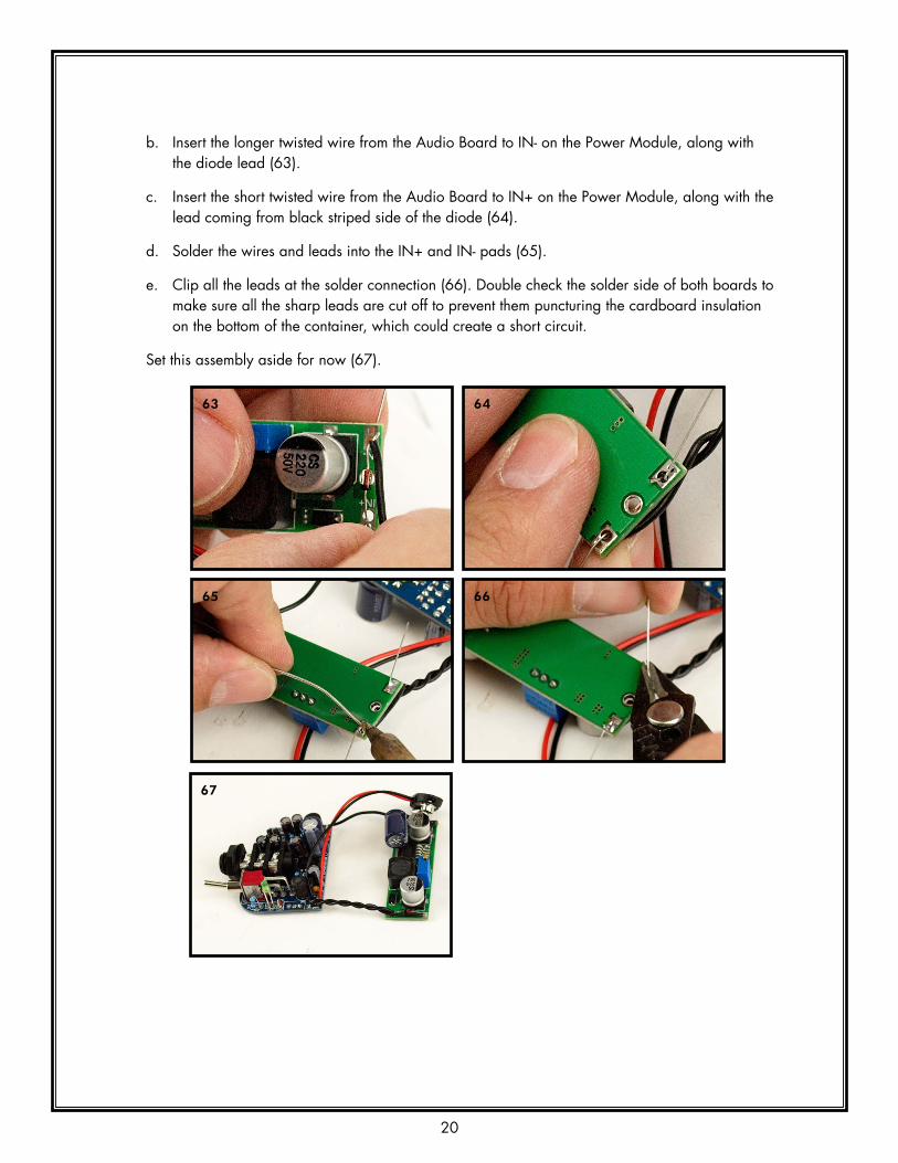
b. Insert the longer twisted wire from the Audio Board to IN- on the Power Module, along with the diode lead (63).
c. Insert the short twisted wire from the Audio Board to IN+ on the Power Module, along with the lead coming from black striped side of the diode (64).
d. Solder the wires and leads into the IN+ and IN- pads (65).
e. Clip all the leads at the solder connection (66). Double check the solder side of both boards to make sure all the sharp leads are cut off to prevent them puncturing the cardboard insulation on the bottom of the container, which could create a short circuit.
Set this assembly aside for now (67).
63 64
65 66
67

21
XLR JACK1. Prep the Mic Cable, part CB-20-12:
a. Strip off about 1/2” (13 mm) of outer insulation from the 12” (30 cm) mic cable. When stripping the outer insulation be careful not to cut too deep and cut through thin copper wires acting as the cable shield.
b. Pull all of these copper shield wires to one side of the cable and twist them together (68).
c. Pull the layer of foil and the cotton strings to the other side of the cable and cut all of them off with your snips (69, 70).
d. Strip off about 1/8” (3 mm) from the white and red wires (71).
e. Tin the twisted copper shield wire, the red wire, and the white wire (72).
Repeat Step 1a - 1e for the other end of this cable.
68
69 70
71 72

22
2. Disassemble the XLR jack (P1):
a. Unscrew the tailpiece, remove the strain relief, and then push the pins out of the housing. You may need to use a pencil or screwdriver to help push out the pin insert.
b. Place the tailpiece and the strain relief onto the cable as shown
73 74
3. Solder the wires to the pin insert:
a. Take a close look at the pin insert. Note how the pins are numbered (75). Mount the pin insert in a clamp if you have one, with the pins oriented so they appear as three troughs (76). Tin each pin with solder.
75 76
b. Solder the white wire to Pin 2, at left (77).
c. Solder the red wire to Pin 3, in the center (77).
d. Solder the ground wire to Pin 1, at right (78).
77 78

23
4. Reassemble the Jack:
a. Slide the strain relief up to the pin insert. Make sure the key on the insert is aligned with the key on the strain relief.
b. Hold the housing so its release button is facing down; you need gravity to hold this open for you. Carefully line up the keys on the insert and relief with the slot in the housing and gently press the pin insert and strain relief into the housing, (79). Be very careful not to disturb your nice new solder connections. Slide the strain relief and pin insert into the housing until they are seated completely inside, flush to the end of the housing.
c. Screw on the tailpiece (80).
79 80

24
THE CONTAINERYou must drill four holes in the box, and make two snips in the lid. Be very careful with this step. The overall look and fit of your Espresso will depend a lot on your work here. You will likely get better results if you locate all holes with a punch, then drill with 1/8” bit, then gradually move up through a few intermediate bits until you arrive at the final size. It also makes a big difference if the bits you use are sharp!
1. Drill the Box
a. Place the bottom of the can accurately upon the template. Pay attention to where the hinge-side of the box is! (81)
b. Use a fine, sharp marker to make four vertical marks up the sides of the can to indicate the horizontal position of the holes(82).
c. Use a ruler to carefully measure up from the can bottom and make a cross to mark the centers of the holes (83, 84).
81 82
83 84

25
d. Use a center-punch or a nail to create a dimple at the centers of the holes (85).
e. Carefully drill the four holes with your 1/8” (3mm) bit (86).
f. Re-drill all four holes with the 5/32” (3mm) bit.
g. If you have some more bits handy, or a step-bit (87), use them to work your way up to the final sizes of the three holes on the end of the can (88).
85 86
87 88
h. You will likely have some ugly burrs inside the box. Clean these off with a small file or a little grinding wheel, like a Dremel tool, if you have one.
2. Snip the Lid
a. Lay the box lid flat on the template, paying attention to the position of the hinge. Use your marker to mark the two snip-lines up the side of the lid (89). Note that the intention is for these two snips to evenly bracket the middle hole. Shift the lines if necessary to get the hole centered between them.
89 90

26
b. Use your sheet metal snips to carefully snip upward through the side of the can lid (91). Make one snip along each line, not lots of short snips. Aim for a spot just below the top of the can (92).
c. Fold the flap into the interior of the lid, pressing it snugly to the top (93).
d. Use pliers or large screwdriver to VERY GENTLY press the fold down to the lid (94). It does not take much pressure, and if you press too hard you will mar the exterior of the lid.
e. Use some isopropyl alcohol and a rag or cotton swab to clean the marks off your can.
91 92
93 94
95
Well done. Treat yourself to a root beer.

27
PUTTING IT ALL TOGETHERWe’re almost there!
1. Cardboard Base: Trim the cardboard base (CD-10-10) to fit neatly inside the bottom of the can. The template may be helpful (96-99).
96 97
98 99
2. Grommet: Fit the grommet (HD-20-02) into the 3/8” (9.5mm) hole at far left (100).
100

28
3. Now we will assemble the XLR cable to the circuit boards.
a. Thread the XLR cable through the grommet, from the outside to the inside, and slide the 7mm heat-shrink onto the cable (101).
b. Solder the XLR wires to the Audio Board at P1. The twisted shield wires go to the square pad; the white wire goes to the center pad; and the red wire goes to the pad closest to C2 (102).
c. Slide the heat-shrink down over the solder joints (103) and shrink it down with your heat gun, lighter, or soldering iron (104). Take your time and be careful not to overheat the components on the board.
101 102
103 104
105

29
4. Install the boards into the can.
a. With needle-nose pliers, gently bend the LED over until not quite horizontal (106).
b. Now retract the XLR cable and carefully draw the circuit boards into the can. Maneuver the switch and the jack into their holes (107).
c. Maneuver the Power Module into the can and gently press it into place. Push the wires around to get it to seat well (108).
d. Seat the audio board firmly against the inside of the end of the can and apply the nut to the output jack (109). Finger tighten, re-seat the board tight against the can, and gently tighten the nut with pliers.
106 107
108 109
e. With needle nose pliers, maneuver the LED to peek out through its hole in the side of the can (110, 111).
110 111
30
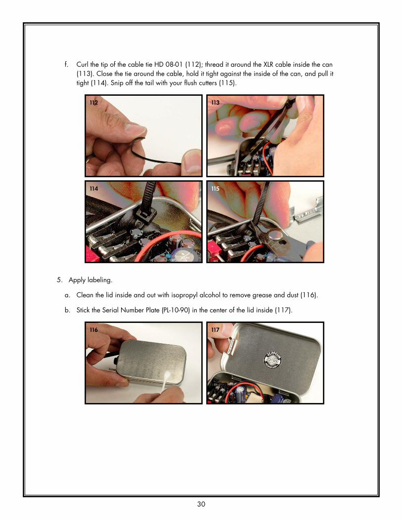
f. Curl the tip of the cable tie HD 08-01 (112); thread it around the XLR cable inside the can (113). Close the tie around the cable, hold it tight against the inside of the can, and pull it tight (114). Snip off the tail with your flush cutters (115).
112 113
114 115
5. Apply labeling.
a. Clean the lid inside and out with isopropyl alcohol to remove grease and dust (116).
b. Stick the Serial Number Plate (PL-10-90) in the center of the lid inside (117).
116 117

31
c. Carefully apply the Espresso sticker to the lid outside. Be careful not to trap air under the label or you will likely end up with bubbles (118,119).
118 119
That’s it! Congratulations! Good job! Look at that nice thing. Go treat yourself to a snack, and then we will test your new phantom power supply.

32
TESTINGThe testing procedure consists of verifying things are properly connected, checking some key voltages, setting the proper phantom power voltage, and then attaching a microphone to the XLR jack and plugging it into a mixer to see how it sounds.
1. Refer to “Figure 4: Test Points”. With no battery installed, set your multimeter to the continuity testing setting and make sure you have continuity between the following:
• TP1 (test point 1): The square pad labeled “SMPS” on the audio board to the “IN+” pad of the power supply module. Also test to make sure that none of the other test points (highlighted in red on Figure 4) make continuity with TP1.
• TP2: The ground of the audio board (you can use the sleeve of the 1/4” jack) to the “IN-” pad of the power supply module (120). Once again, make sure that none of the other test points make continuity with TP2.
• TP3: The square pad labeled “HV” on the audio board to the “OUT+” pad of the power supply module. Make sure nothing else makes continuity with TP3.
• TP4: Pin 2 on the XLR jack to the pin on J2 (the jumper header) labeled TP4. Make sure nothing else makes continuity with TP4.
• TP5: Pin 3 on the XLR jack to the pin on J2 (the jumper header) labeled TP5. Make sure nothing else makes continuity with TP5.
• If any of these tests fails to show continuity or makes continuity where it shouldn’t, check your work until you find and fix the problem. Do not proceed until you have fixed any problems.
Figure 4: Test Points

33
120 121
2. When everything is connected the way it should be, plug a good-quality 9V battery into the Espresso. (See “Battery Life” in the Espresso Owners Manual.) Do NOT connect a microphone yet! Set your multimeter to measure DC voltage. Turn your Espresso on; you should see the LED light up. Measure from ground (you can use the sleeve of the ¼” jack) to the following test points:
• TP1 should be about 9V (depending on how fresh your battery is).
• TP3 should be about 42V, depending on how your phantom voltage supply is set (121). We set the voltage to about 42V prior to shipping. See “Voltage Adjustment” in the Espresso Owners Manual.
• Pin 2 and Pin 3 of the XLR jack should both be about the same as TP3.
3. Next plug a microphone that needs phantom power into the Espresso. We use a Cortado Contact Mic by Zeppelin Design Labs for testing our Espressos – no surprise there (122). We recommend you use a microphone that draws no more than 5mA current. With the jumpers in the “Unbalanced” position, use an unbalanced instrument cable from the Espresso’s output jack to plug into a mixing console or instrument amplifier. Turn the Espresso on and listen to your microphone. It should work! (123) If you hear any motorboating (low frequency oscillations or a thumping sound) then adjust the phantom voltage until it goes away (please read “Voltage Adjustment” in the Espresso Owners Manual). Oscillation can also occur when the battery is drained, so sometimes changing to a fresh, decent battery will also help.
122 123
That’s it! You are done!! Congratulations.
You are good to go. Now read the Espresso Owners Manual for further instructions on using and adjusting your new power supply.

DRILL 3/8" (9.5mm) HOLE5/16" (8mm) UP FROM BOTTOM
DRILL 7/16" (11mm) HOLE7/16" (11mm) UP FROM BOTTOM
DRILL 1/4" (6mm) HOLE7/16" (11mm) UP FROM BOTTOM
DRI
LL 5
/32"
(3.5
mm
)H
OLE
5/1
6" (8
mm
)U
P FR
OM
BO
TTO
M
PLACE BOTTOM OFCAN ON TEMPLATE
HINGE SIDE
HINGE SIDE
PLACE TOP OF LIDON TEMPLATE
CUT TWO SNIPSJUST OVER 1/4" (7mm)
UP. FOLD BACK INTO LID.
CARDBOARDBASE OUTLINE
ZEP
PEL
IN D
ESIG
N LA
BS,
LLC
2950
N W
ESTE
RN A
VE
CH
ICA
GO
IL 6
0618
WW
W.Z
EPPE
LIN
DES
IGN
LABS
.CO
M
REV
. DA
TE 7
/12/
2016
PAG
E 1
of 1
ESPR
ESSO
PO
RTA
BLE
PHA
NTO
M P
OW
ER S
UPP
LYFU
LL S
IZE
DR
ILLI
NG
TEM
PLA
TEC
2016
ZEP
PELI
N D
ESIG
N L
ABS
, LLC


36