the electric propulsion library of espss for system simulation
TRANSCRIPT

The 33st International Electric Propulsion Conference, The George Washington University, USAOctober 6 – 10, 2013
1
The Electric Propulsion Library of ESPSS for System Simulation
IEPC-2013-403
Presented at the 33rd International Electric Propulsion Conference, The George Washington University • Washington, D.C. • USA
October 6 – 10, 2013
Christophe R. Koppel1
KopooS Consulting Ind., 57 rue d’Amsterdam 75008 Paris, France
Fernando Rodríguez Lucas2
Empresarios Agrupados, c/Magallanes 3, 28015 Madrid, Spain
and
Dr. Francesco Di Matteo3 and Dr. Johan Steelant4
ESA-ESTEC , Keplerlaan 1, 2201AZ Noordwijk, The Netherlands
Abstract: The paper describes the phase three of the work performed for the implementation and validation of an electric propulsion system modelling library of ESPSS (European Space Propulsion System Simulation) within the existing tool EcosimPro®. EcosimPro® is a Physical Simulation Modelling tool developed in an object-oriented visual simulation environment capable of solving dynamic systems written by equations and discrete events. It solve both transients and steady states. This tool, with the propulsion library ESPSS for example, allows the user to design (and to draw at the same time) the propulsion system with components like tanks, lines, orifices, valves, thrusters, etc. The design capabilities are enhanced by components from the thermal library (heaters, thermal conductance, radiators), from the control library (analogue/digital devices), from the electrical library, etc. The paper presents several new components added to the propulsion library. These improvements of ESPSS are updating and extending multiple libraries to represent a functional propulsion system, e.g. fluid properties, pipe networking including multi-phase fluid flow, two-phase two fluids tanks with gravity or accelerations effects, non-adiabatic combustion chambers, chemistry, turbo-machinery, etc. The paper presents the modelling of electric propulsion systems performed in order to check the implementation of the new components especially the thruster, the PPU (or PSCU), the xenon flow control XFC (or XFCU), etc. The Electric Propulsion (EP) library allows the user to simulate the operations necessary for the activation of the electric propulsion on-board of a satellite and to simulate the outputs of the several telemetries and functional characteristics. In addition, this library includes a port so called "RAMS" for simulating some predetermined failures cases for each component.The research leading to these results has received funding from ESA contract N°4000103800/11/NL/CP
1 Chief consulting engineer, [email protected] Project Manager, EcosimPro/PROOSIS Development Group, [email protected] Aerothermodynamics and propulsion analysis, [email protected] Propulsion engineer and technical officer, Aerothermodynamics and propulsion analysis, [email protected].

The 33st International Electric Propulsion Conference, The George Washington University, USAOctober 6 – 10, 2013
2
Nomenclature
F parameter of model, thrust efficiencye parameter of model, electrical efficiencygoIsploss parameter of model, losses (m/s)F Thrust force (N)Pe Electrical input power (W)
propm total mass flow rate (kg/s)
g0.Isp specific impulse (m/s)
dI discharge current or beam current (A)
dU discharge voltage (V)
kI parameter of model, proportion between current and mass flow
dSetU wanted discharge voltage in operation (V)
OpI max discharge current maximum at constant voltage (A)
a negative resistance of the voltage current characteristic (-1)Ishort short circuit current (A)Kp, Ki, Kd gains
I. Introduction
HE paper presents first a simulation concept that is a system engineering tool dedicated for complex systems, the European Space Propulsion System Simulation (ESPSS) libraries, and in a second part a specific Electric
Propulsion (EP) library dedicated first for the operations of any EP system.
II. European Space Propulsion System Simulation (ESPSS) background
EcosimPro® is a Physical Simulation Modelling tool developed for ESA by Empresarios Agrupados Internacional (Spain) since 1989. EcosimPro® was a precursor and now with its 24 years of careful growing it belongs to the last generation of the common engineering tools after computer aided design (CAD) and integrated engineering analysis tools available on classical laptops. The kernel of EcosimPro® is an expert solver of all the equations set in the different components of a system. Solving all the equations together has been found extremely efficient and this justify the main feature of the tool which is to describe every component in terms of symbolic equations. Thanks to such expert solver, the tool allows to manipulate components like objects that can be independently further developed with more sophisticated equations. EcosimPro® is based on a visual simulation tool for solving simple and complex physical processes that can be expressed in terms of equations (including ordinary differential and differential-algebraic) and discrete events (especially for the commands or triggering events).Practically, the modelling of physical components is based on a basic “EcosimPro language” (EL), an object-oriented programming language which is very similar to other conventional programming languages (Basic) but is very powerful to write any equations and differential equations for modelling continuous and discrete processes. EcosimPro employs a set of libraries containing various types of components (mechanical, electrical, pneumatic, hydraulic, etc…) which can be interconnected to model complex multi-domain dynamic systems. The ESA ESPSS is a set of EcosimPro® libraries written to model all aspects of a functional propulsion system. For example, as a tool ESPSS is relying on 1D flow equations, thermodynamic relationships and real fluid properties, there is no need for fudge factors, therefore the results of the simulations could be considered as general as long as the flow is one-dimensional and homogeneous (either as mono-phase, or two-phase state or as a mixture).
III. European Space Propulsion System Simulation (ESPSS) Libraries
The following libraries have been developed in the phases 1&2 of the project ESPSS: “Fluid Properties”, “1-D Fluid Flow”, “Tanks”, “Combustion Chambers” and “Turbomachinery” libraries. An overview of these propulsion libraries with some validation cases is presented in ref. 1.
As the third phase of the project ESPSS started few years ago, only the new improvements are discussed in the following chapters. One among them is the new Steady-State library compatible with other parts of ESPSS along
T

The 33st International Electric Propulsion Conference, The George Washington University, USAOctober 6 – 10, 2013
3
with two new libraries for satellites: the SATELLITE library and the Electric propulsion library (EP library). Those improvements will be added for the next release of ESPSS to its users 2.
IV. European Space Propulsion System Simulation (ESPSS) Improvements
The improvement of ESPSS are numerous, here are reported only some significant points for the ESPSS libraries FLUID_FLOW_1D, TURBO_MACHINERY , COMB_CHAMBERS and TANKS:
o In the Junction components the supersonic conditions are allowed as option, and can be detected automatically.
o The heat Exchanger have been upgraded for cross flow dispositions accounting for several baffles and tube passes.
o A more robust version of the Cold Thruster component using supersonic junctions (non adapted conditions can be calculated included the shock inside the nozzle).
o Valves have been upgraded to consider EqualPercentage, Linear, QuickOpening or user-defined laws.o Fluid Cavities (not the simple Volumes) and Tank models account for the volume expansion due to wall
compressibility.o Added new input data and options for right, "Y" and User defined Tee component.o Nozzle & chamber diameters reconstruction is included in the continuous block allowing geometry
redefinition during a simulation.o New components are available for imposed static boundary conditions (intakes).o N2, He,O2, H2, CH4 real properties files are rebuilt with more points in pressure & temperature. Moreover,
extrapolating in real properties at P>Pmax, T<Tmin or under two-phase flow is better detected and treated.o 1D Tanks include film boiling bubbles formulation (as a new option) and better simulation of the
generalized boiling process.o Condensation (raining) flow is now optional: Droplets can remain as a fog in the ullage volume or can drop
to the liquid volume at a given speed.o Pumps model: Table of loss of head vs. net positive suction head (NPSH) and compressibility effects due to
pump cavitations have been included.o Combustor models are more robust simulating start-ups and shutdown sequences.o New components are available to compute the delay in the transport of the combustion products also
permitting the simulation of a mixture of combusted gases and pure fluids (chamber with more than 2 injectors).
In addition a new library called STEADY has been added to ESPSS for simplified cases of Steady states. The STEADY library contains a complete set of components (combustors, cooling-circuits, nozzles, turbines, pumps and valves) able to calculate the performances of any rocket engine cycle type under design and off-design conditions.
A new “SATELLITE” library deals with interactions of the Satellite Attitude and Orbit Control System (AOCS) with its propulsion subsystem. This library includes an orbit propagator as well as management of variable inertia and dynamic evolution of center of mass due to propellant consumption and inertial acceleration due to the thrusts or to the perturbing forces. The satellite library contains the main components, shown in Fig. 1, needed to build a satellite AOCS with the major interactions and perturbations that occurs in flight3,4,5. Moon and Sun perturbations, mainly corrected
by the use of thrusters for the North-South station keeping of a GEO satellite,
Earth flatness or so called "J2" perturbations to be used for the helio-synchronous satellites,
Sun pressure interaction with the solar arrays of the satellite.
In addition, a control of the satellite attitude can be added (using the existing components of the existing CONTROL library) for performing an Earth Pointing with a set of actions on the reaction wheels or on a set of thrusters or Electric thrusters. Finally the Electric Propulsion "EP" library allows the user to simulate the operations needed to activate the electric propulsion aboard a satellite and to simulate the outputs of the several telemetries and functional characteristics. In
Fig. 1 Palette of components for the SATELLITE library of ESPSS

The 33st International Electric Propulsion Conference, The George Washington University, USAOctober 6 – 10, 2013
4
addition this library includes a port so called "RAMS" for simulating some predetermined failures cases for each component. This EP library is described in more detail below.
V. The Electric Propulsion "EP" Library
EP is an EcosimPro® library for the transient simulation of electric propulsion systems. Because the numerous possible systems, this library is more oriented as an example design for building such system. The most important features are the following:
o Thrusters model provided with tabulated example of characteristic adapted to Hall effect thrusters (PPS13506), Gridded Ion Engines (T6, EsaXX7) and for UserDefined models.
o Xenon Flow Contoller (XFC8) based on the use of a thermothottle for the control of the mass flow rate and Filter Units (FU) components are more oriented for Hall effect thrusters (PPS1350), but can be used without difficulties with Gridded Ion Engines (T6, EsaXX).
o The Power Processing Unit (PPU9,10) component allows receiving simple Tele-command list in the experiment to successively perform the operations.
The general design of the components of EP LIBRARY is coming from open bibliography references. The users are encouraged to modify the design in order to match with their own performances and characteristics. The EP components can be connected to other ESPSS libraries (FLUID_FLOW_1D components and to ELECTRICAL components) in order to simulate a complete Electric propulsion system.The palette of objects designed for this library ) is shown in Fig. 2, it comprises EPthruster, FU (filter unit), XFC (xenon flow controller), PPU (power processing unit), and a Fail_Processor and Connect (a fluid connectionenabling on command a leakage).
VI. Simplified General model of EP thruster
As sketched in Fig. 2, the component EPthruster is equipped with 2 ports. Ports are fundamental communication interface between components in Ecosimpro®, comprising the variables needed as in the real system. For the EPthruster, one port is dealing with high voltage (and high current, and other parameters) the other is a fluid port for the input of propellant (i.e. xenon coming from an existing ESPSS library FLUID_FLOW_1D fluid port). That means that the system build with the EP library will be compatible with the numerous existing components for all what concern the propellant sub-system.Regarding the thruster itself, the model used for the relation "Thrust, Power and Isp" is already developed11.This is a simplified model based on 2 parameters (F and goIsploss), but valid for Hall and Ion thrusters (with F in N, Pe in W and g0.Isp in m/s).
Ispg
IspgIspg
PF
Loss
eF .
.2
1 02
0
2
0
(1)
With a given total mass flow rate propm (kg/s) and the thrust force F, the g0.Isp (m/s) can be deduced:
propmFIspg .0
(2)
Thus the two equations (1) and (2) make the variable g0.Isp as algebraic and thus those equations are to be solvedtogether in a so-called "box" of EcosimPro®. It is to be highlighted that this process is automatic in EcosimPro®
Fig. 2 Palette of components for the EP library of ESPSS

The 33st International Electric Propulsion Conference, The George Washington University, USAOctober 6 – 10, 2013
5
because the model is only written in terms of symbolic equations, the expert solver of EcosimPro® will recognize the
need for such algebraic loop. In addition the current dI (discharge current or beam current) is derived from the total
mass flow rate by a relation with one coefficient kI (theoretically one electron for one ion) which is actually also linked to the fraction of propellant feeding the anode with respect to the total mass flow rate:
Ipropd kmI with Id in A (3)
And the total input power eP is derived from the voltage dU (discharge voltage or beam voltage) and current by a
relation with one coefficient e:
d
eed I
PU with Ud in V (4)
Two last equations are coming from the fluid port that impose the mass flow rate and from the PPU that impose the voltage
XFCthebygivenm prop ___ and PPUthebygivenU d ___ (5,6)
Every model is based from correlations formulae, but those formulae are customizable: users who want to use other thrusters have to adjust the parameters available in order to fit with the integrated formulations.
VII. Simplified General model of PPU
The model of the PPU has two parts: Hardware and Software.o The hardware part contains all the devices that are used in the PPU based internally on several already
existing components of the ESPSS libraries.o The software part is dealing with the specific logic of operations managed into the PPU.
A. PPU hardware From the block diagrams found in the bibliography12,13,14, the PPU (or PSCU) component shall include 5 power
supplies.The PPU hardware comprises components from other ESPSS libraries as sketched in Fig. 3: components fromELECTRICAL library (green color) and CONTROL library (orange color). In addition some simple equations are added (symbolized by dashed lines in the sketch) for linking appropriately some components inside the object PPU :
the characteristic of the Anode power supply current ( dI ) is
linked to the input of the PID. Also the output of the PID is linked to the current of the Thermothrottle current source. All the voltage and current sources inside the PPU are linked to two ports (multi-variable ports) for feeding the thruster system: "Thr" for the high voltage port and "Xfc" for the lower voltage port. Two other ports are implemented for the inputs: the bus voltage and the TcTm port for the direct and digital telecommands&telemetries .All the current sources or voltage sources are simulated by standard components of ESPSS except the main power source (Anode power source) which includes a particular important feature (needed for some Hall Effect thrusters) with a limited power discharge voltage-current characteristic. Moreover, the control loop of the discharge current is active only in the domain grayed in Fig. 4.
The simple equation to model this Anode power source used is
Fig. 3 PPU Hardware model build from existing libraries

The 33st International Electric Propulsion Conference, The George Washington University, USAOctober 6 – 10, 2013
6
)0max. max OpddSetd I,I(aUU (7)
where the coefficient a represent a negative resistance (in ohm), a beingnegative infinite for GIE and simply negative for HET ( a <0). For Ud=0, the current is defined by Ishort which is a data of the model.The other power supplies for feeding the devices included in the thruster system are:
o Magnet power supply,o Igniter/ Keeper power supply,o Heater power supply,o Acceleration grid power supply.
A last power supply deals with the control loop for the mass flow rate
o In the case of Hall Effect thrusters (or thruster using thermal flow controller), this is a current source where the current level is given by the error between the actual discharge current and the goal IdSet given in the data of the component or set by telecommand.
o For initialization purpose, when the thruster is still off ( dI =0) the current level of the current source shall
be set to an initial current IttSet (sometime called warm-up current).o The control loop may use according to the gains Kp, Ki, Kd a proportional (P) loop control, or a
proportional integral (PI) loop control or full proportional integral derivative (PID)loop control.
o The PID implemented in the PPUcomponent of the EP library is a standard PID coming from the CONTROL Library with most of the default settings. The
current position corresponds to the dI
measured while the wanted position of dIis IdSet. The output toward the thermothrottle is the current Itth as sketched in Fig. 5.
Because the increase of Itth decreases the mass
flow rate and thus decreases the current dI , the
gain of the controller shall be negative (-1). The time constant of integration has been set appropriately in order to follow the expected behavior of the device. The range of output for Itth is defined in the data. In the case of Ion engine, if the flow controller is different from above, the user shall use the available components of the ESPSS library (heaters, proportional valves) to build the relevant control loop because up to now, the details of the control for those thrusters are not disclosed. But it must be highlighted that the HET XFC can be used also with Ion engines.
B. PPU software For Hall Effect thrusters the following accurate description available in the bibliography10 is taken into account:
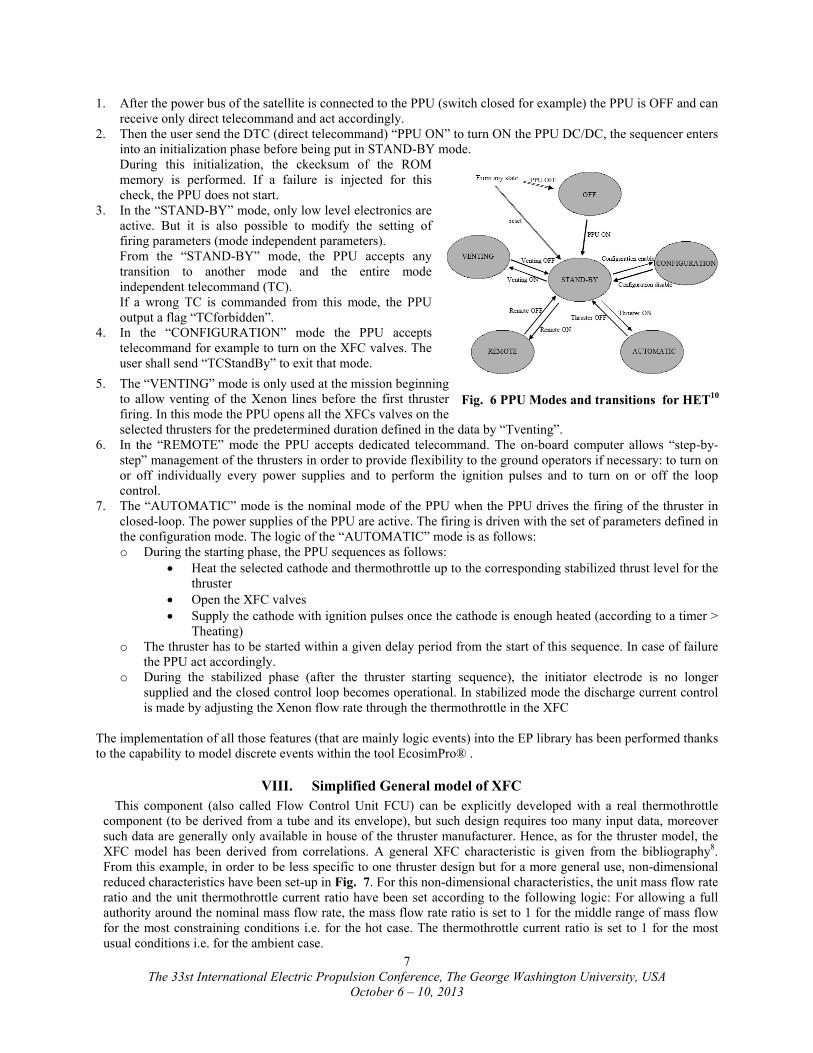
The PPUs exchange data with the on-board computer. According to the received command, the PPU enters into one of its six possible modes: OFF, STAND-BY, CONFIGURATION, VENTING, AUTOMATIC and REMOTE. These transitions are sketched in Fig. 6 . Their description is as follows:
Fig. 4 Example PPU voltage-current characteristic 9
Fig. 5 Control loop of the thruster discharge current Id by the thermothottle current Itth courtesy www.newport.com
Ud
UdSet
UminOp
IminOp ImaxOp Ishort Id
Area where the control loop is active
Permission to use granted by Newport Corporation. All rights reserved.
The 33st International Electric Propulsion Conference, The George Washington University, USAOctober 6 – 10, 2013
7
1. After the power bus of the satellite is connected to the PPU (switch closed for example) the PPU is OFF and can receive only direct telecommand and act accordingly.
2. Then the user send the DTC (direct telecommand) “PPU ON” to turn ON the PPU DC/DC, the sequencer enters into an initialization phase before being put in STAND-BY mode. During this initialization, the ckecksum of the ROM memory is performed. If a failure is injected for this check, the PPU does not start.
3. In the “STAND-BY” mode, only low level electronics are active. But it is also possible to modify the setting of firing parameters (mode independent parameters). From the “STAND-BY” mode, the PPU accepts any transition to another mode and the entire mode independent telecommand (TC). If a wrong TC is commanded from this mode, the PPU output a flag “TCforbidden”.
4. In the “CONFIGURATION” mode the PPU accepts telecommand for example to turn on the XFC valves. The user shall send “TCStandBy” to exit that mode.
5. The “VENTING” mode is only used at the mission beginning to allow venting of the Xenon lines before the first thrusterfiring. In this mode the PPU opens all the XFCs valves on the selected thrusters for the predetermined duration defined in the data by “Tventing”.
6. In the “REMOTE” mode the PPU accepts dedicated telecommand. The on-board computer allows “step-by-step” management of the thrusters in order to provide flexibility to the ground operators if necessary: to turn on or off individually every power supplies and to perform the ignition pulses and to turn on or off the loop control.
7. The “AUTOMATIC” mode is the nominal mode of the PPU when the PPU drives the firing of the thruster in closed-loop. The power supplies of the PPU are active. The firing is driven with the set of parameters defined in the configuration mode. The logic of the “AUTOMATIC” mode is as follows:o During the starting phase, the PPU sequences as follows:
Heat the selected cathode and thermothrottle up to the corresponding stabilized thrust level for the thruster
Open the XFC valves Supply the cathode with ignition pulses once the cathode is enough heated (according to a timer >
Theating)o The thruster has to be started within a given delay period from the start of this sequence. In case of failure
the PPU act accordingly.o During the stabilized phase (after the thruster starting sequence), the initiator electrode is no longer
supplied and the closed control loop becomes operational. In stabilized mode the discharge current control is made by adjusting the Xenon flow rate through the thermothrottle in the XFC
The implementation of all those features (that are mainly logic events) into the EP library has been performed thanks to the capability to model discrete events within the tool EcosimPro® .
VIII. Simplified General model of XFC
This component (also called Flow Control Unit FCU) can be explicitly developed with a real thermothrottle component (to be derived from a tube and its envelope), but such design requires too many input data, moreover such data are generally only available in house of the thruster manufacturer. Hence, as for the thruster model, the XFC model has been derived from correlations. A general XFC characteristic is given from the bibliography8. From this example, in order to be less specific to one thruster design but for a more general use, non-dimensional reduced characteristics have been set-up in Fig. 7. For this non-dimensional characteristics, the unit mass flow rate ratio and the unit thermothrottle current ratio have been set according to the following logic: For allowing a full authority around the nominal mass flow rate, the mass flow rate ratio is set to 1 for the middle range of mass flow for the most constraining conditions i.e. for the hot case. The thermothrottle current ratio is set to 1 for the most usual conditions i.e. for the ambient case.
Fig. 6 PPU Modes and transitions for HET10

The 33st International Electric Propulsion Conference, The George Washington University, USAOctober 6 – 10, 2013
8
With such logic, the normal operation of the XFC control can start at ambient condition with the nominal mass flow rate, and in the event the temperature of the device increase, then the corresponding thermothrottle current have to decrease (automatically by the PID of the PPU) for maintaining the mass flow rate.Such curves of mass flow rate ratio versus the thermothrottle current ratio are put in a Table 2D "mfrr"(feature of EcosimPro® ) as a function of the temperature condition case and the thermothrottle current ratio. When the current temperature of the XFC is specified, linear interpolation with the temperature case is performed. The effect of the pressure is taken into account by a pressure ratio along with an exponent (set by default to n=2). Finally the XFC model for the mass flow
rate propm versus the pressure P and the current Itth is
described by the following equation where the pressure P0, the current Itth0 and the mass flow rate mfr0 are set in the data of the component:
000 , T_K).mfr/Itth.mfrr(Itth)(P/Pm nprop (8)
IX. Model Description of The Fail Processor Components
Regarding the fail processor function, two approaches seems possible1. The creation of a new port for transferring the failure cases so called “RAMS events” to the components. 2. The management of all the RAMS events foreseen with a global variable
The first approach is in line with the concept of a simulation tool using objects connected each other with their ports. This is the most interesting aspect of this approach. However the drawback is that several links should be added to the objects for connecting those ports together to a main fail processor: this may add a complexity to the system design when the user wants to play with some RAMS events, and this is much less intuitive than for real functional links like fluid or electric links. The second approach however relies on events that are coming via a global variable (feature available within EcosimPro®). In this second case, the user does not see any links between the fail processor and any of its components. But the presence of a Fail processor component shall be added to the system design for enabling an also highlighting this feature. For the two cases considered, the designer of the component shall include into each component the actions relevant to a specific RAMS event. In this aspect the two approaches are similar. Because the system simulation is firstly intended to simulate the nominal behavior of the system and second it may also simulate some failure cases, the second approach has been preferred. In addition one shall mention that this approach was already followed in the simulation of the SMART-1 Electric Propulsion System15.The RAMS events have to be derived from the Failure Modes, Effects and Criticality Analysis (FMECA). Among them for example the list is the following:
o For thrusters: short between grids (in the case of GIE); swirl torque; thrust orientation,..o For the PPU (or PSCU): sudden loss of the anode voltage due to a single event transient, higher power, …o For the propulsion system: leakage components using a specific valve to the vacuum.
The implementation of all those features (that are mainly conditional events) into the EP library has been performed thanks to the capability to model dynamically conditional equations within the tool EcosimPro® .
X. Reference Electric Propulsion System
The reference case of the use of the new components of the EP Library is a simple EP system with one PPU and one thruster. The fluid section for the xenon input is simulated by a constant source (as a perfect pressure regulator output). The sketch of the model is shown in Fig. 8.
Fig. 7 XFC non-dimensional characteristics mass flow versus input current
0
0,5
1
1,5
2
2,5
0 0,5 1 1,5 2 2,5 3
Itth/Itth0
mfr/mfr0
cold
ambient
hot
XFC characteristics reduced
mass flow rate ratio =1 at hot case ; thermothrottle current ratio=1 at ambient case (red dots)

The 33st International Electric Propulsion Conference, The George Washington University, USAOctober 6 – 10, 2013
9
A model by alone is not able to be used without any specific command. Thus in the EcosimPro® environment, one uses the experiment feature where all the commands to the model are specified in a chronological order. In addition one can also update some settings of the model and perform loops for parametric analysis. The experiment includes of course the command to EcosimPro® to run the simulation when wanted
For the reference case, the list of commands is the following (where the chronology of the command is given by the keyword AFTER in seconds):
Table 1: Example of a list of commands to run a simulation of the EP model in an EcosimPro® experiment
Actions Experiment listing
1. Set the bus voltage VDC.V=50
OPERATION and TC LIST
2. Close the bus power switch HPSSPC.b_fire.signal[1] = TRUE AFTER 0.5
3. Direct TC to turn ON the PPU PPU.TcTm.DTC=1 AFTER 3
Sequence of digital TCs in the chronological order
4. Switch to PPU automatic Mode sequence with default settings
PPU.TcTm.TC=TCAutomatic AFTER 8
5. Prepare a TC with a value PPU.TcTm.TC_Value=4.125 AFTER 11
6. Send the TC to specify immediately IdSet the discharge current wanted at ignition (4.125 A)
PPU.TcTm.TC=TCIdSet AFTER 12
7. Prepare a TC with a value PPU.TcTm.TC_Value=5.125 AFTER 409
8. Send the TC to change immediately IdSet the discharge current at time 410s (5.125 A)
PPU.TcTm.TC=TCIdSet AFTER 410
9. Finally, run the simulation for 750 s INTEG_TO(750,10)
Hence a list of 9 commands is used to turn on the EP system with two different settings regarding the discharge current (and all other settings being set at their default value).
The simulation provide the output as expected in Fig. 9 where at time 410 s, one can see the change due to the new discharge current settings and successively in the Fig. 9 the effects on the power (a) , the xenon mass flow rate and its pressure at XFC input (b), the discharge current and thermothrottle current (c), the Isp and thrust (d) and the discharge voltage (e) and the telecommand values (f).
Because the model is dynamic (includes differential equations), the change is not instantaneous, but some time is needed to reaches the steady state after the change has been requested.
Such simulation is very fast requiring only few seconds of computations on a standard laptop.
Fig. 8 Reference case of EP system model

The 33st International Electric Propulsion Conference, The George Washington University, USAOctober 6 – 10, 2013
10
XI. Complete operational system of Electric Propulsion System
In order to show the capabilities of the ESPSS library with the features gained by the use of the EP Library, a complete operational system of EP system has been set up: the xenon system is simulated by a much more realistic system composed of two tanks (with thermal control) with tees, valves and pressure regulation and thermal control and with a final plenum volume before conducting the xenon to the two EP systems (EP1 and EP2).
Fig. 9 Reference case of EP system: simulation results with change of thruster setting at time 410s
Fig. 10 Complete operational EP system
a)Power d) Isp, Thrust
e) discharge voltageb) mass flow rate pressure
c) discharge current thermothrottle current f) Telecommand value

The 33st International Electric Propulsion Conference, The George Washington University, USAOctober 6 – 10, 2013
11
The same list of command as before is used, that is with a change of setting of the discharge current at time 410s. The simulation provide the output as expected in Fig. 11where at time 410 s, one can see the change of discharge current settings. As before, the change is not instantaneous, but some time is needed to reaches the steady state after the change has been requested, and because the model of pressure regulation is much more realistic than before, some tiny effects of the dynamic pressure regulation can be observed in the plot (b), but the overall picture is however quite similar to the previous reference case shown before.
XII. Conclusion
Many features of the European Space Propulsion System Simulation (ESPSS) libraries with the new components of the Electric Propulsion (EP) library have been described in details.
The components of EP library allow simulating the operations needed to be performed for using the electric propulsion in space as well as in ground laboratories.
In addition two simulations models have been described in order to show the reference case simulation of an EP system and to show an extension of the system simulation to a complete EP system thanks to the features available included in the propulsion library ESPSS.
The users of ESPSS will be able to enhance the models included in the EP library to fit with their own characteristics of thruster or other devices in order to deliver to their customer operational models.
One shall add that the tool EcosimPro® provides in its environment a full capability for connections between the models and simulations developed within this software and other ones, from the generation of C++ code itself, reusable in other applications, to the interface with Microsoft environments (Microsoft Excel© and Microsoft Visual Basic©) and Matlab simulink©. This flexibility can be very appreciated for using operationally the models designed with ESPSS.
Acknowledgments
The research leading to these results has received funding from ESA contract N°4000103800/11/NL/CP
References1Koppel C. R., Moral J., De Rosa M., Vara R.P., Steelant J., and Omaly P., “Satellite Propulsion Modelling With Ecosimpro:
Fig. 11 Complete operational EP system: simulation results with change of thruster setting at time 410s
a)Power d) Isp, Thrust
b) mass flow rate e) discharge voltage pressure
c) discharge current thermothrottle current f) Telecommand value

The 33st International Electric Propulsion Conference, The George Washington University, USAOctober 6 – 10, 2013
12
Comparison Between Simulation And Ground Tests”, presented at EUCASS 2009, published by EDP Sciences, 2011 in “ Progress in Propulsion Physics 2 (2011) 743-764.2ESPSS release 3.0.
3Koppel C R., De Rosa M., Moral J. and Steelant J. “Effects of a Satellite Mission on the Propulsion Subsystem”, SP2012
2364281 Space Propulsion 2012, 7 – 10 May 2012,Bordeaux, France4Koppel C R., De Rosa M., Moral J. and Steelant J. “A Satellite Library In EcosimPro for fhe Aocs' Effects on the Propulsion
Subsystem”, 5TH ICATT 2012, ESA/ESTEC, Noordwijk, The Netherlands 29 May – 1 June 20125Koppel C R. “ESPSS SATELLITE LIBRARY”, ESPSS Workshop, ESA/ESTEC, Noordwijk, The Netherlands 21 May – 23 May 20136Dumazert Pierre, Marchandise Frédéric, Prioul Mathieu, Darnon Franck, and Jolivet Laurent, AIAA 2003-4549, PPS® 1350-G ,
39th Joint Propulsion Conference, Huntsville, Alabama, July 2003.7Bassner H., Bond R., Groh K., 1997ESASP.398, page 251-257 "The ESA-XX Ion Thruster", ESA Space propulsion conference,
1997.8Duchemin Olivier et al., AIAA 2010-6696 “Electric Propulsion Thruster Assembly for Small GEO”
9Bourguignon E. and Scalais T. , "High Power Processing Unit For Stationary Plasma Thruster", IEPC 2003-0067, International
Electric Propulsion Conference10
Gray Howard, Provost Severin, Glogowski Michael and Demaire Alain, "Inmarsat 4F1 Plasma Propulsion System Initial Flight Operations", IEPC-2005-082, Presented at the 29th International Electric Propulsion Conference, Princeton University, October 31 – November 4, 200511
Koppel Christophe, Barral Serge, « High Specific Impulse Thrusters Behavior » Atelier Cnes Trajectoires A Poussee Faible, workshop LOTUS 1, 7-8 mars 2000, Toulouse.12
Osuga Hiroyuki et al., IEPC-2005-114 “Development Status of Power Processing Unit for 200mN-class Hall Thruster” Mitsubishi Electric Corporation13
Brophy J.R., " Ion thruster performance model", NASA CR-174810, December 198414
Gollor Matthias and Weinberg Simon. AIAA 2008-5284 “Electric Propulsion Electronics Activities in Europe” European Space Agency, Michael Boss Astrium GmbH, Federico de la Cruz Astrium CRISA, Paolo Galantini Galileo Avionica S.p.A., Eric Bourguignon Thales Alenia Space ETCA, 44th AIAA/ASME/SAE/ASEE Joint Propulsion Conference & Exhibit 21 - 23 July 2008, Hartford, CT.15
Alvarez Jesus, Perez-Varra Ramon, Koppel Christophe R. “SESP 2006-435470 Simulation of the Smart-1 Electric Propulsion System With a System Simulation Software Ecosimpro®”, presented at the 9th International Workshop on Simulation for European Space Programmes, 6-8 November 2006 at ESTEC, Noordwijk, the Netherlands