the effects of processing conditions on thermoplastic
TRANSCRIPT

The Effects of Processing Conditions on Thermoplastic PrototypesReinforced with Thermotropic Liquid Crystalline Polymers
Robert W. Gray IV
Thesis submitted to the Faculty of the Virginia Polytechnic Institute and State University in partialfulfillment of the requirements for the degree of
Master of Sciencein
Chemical Engineering
Dr. Donald G. Baird, Chairman
Dr. Jan Helge Bøhn Dr. Richey M. Davis
July 30, 1997Blacksburg, Virginia
Keywords: Polymer, Composite, TLCP, Prototype, and FDM

The Effects of Processing Conditions on Thermoplastic PrototypesReinforced with Thermotropic Liquid Crystalline Polymers
Robert W. Gray IV
This work is concerned with preliminary studies on developing thermoplastic compositematerials suitable for use in fused deposition modeling (FDM). Polypropylene (PP) strandsreinforced with continuous thermotropic liquid crystalline polymer (TLCP) fibrils were generatedin a novel dual extruder process. Strands were then re-extruded to form short fiber compositemonofilaments that were used as feed stock in the FDM 1600 rapid prototyping system.Prototypes containing 40 wt% Vectra A were shown to have tensile properties twice those ofparts built using acrylonitrile butadiene styrene copolymer (ABS), a commercially availablematerial used in the FDM 1600 rapid prototyping system. It was also shown that the finalmechanical properties of a composite prototype can be tailored to a specific application byadjusting the lay-down pattern, increasing the functionality of the prototype. In order to obtainthe maximum tensile properties in these composite prototype, additional studies were performedto determine the effects of thermal and deformation histories on the mechanical properties ofmonofilaments that were re-extruded from long fiber TLCP reinforced strands. Strands wereconsolidated uniaxially at temperatures just above the melting point of the matrix in order todetermine the effects of thermal history, and an approximate 20% reduction in tensile modulusrelative to the modulus of the strands was observed. Monofilaments that could be used as feedstock in FDM were extruded from long fiber TLCP reinforced strands using a capillary rheometerin order to study the effects of capillary diameter, capillary L/D, and apparent shear rate on thetensile properties.
This work was supported by the Army Research Office (Grant No. DAAH04-94-G-0282),the Naval Surface Warfare Center, Dahlgren Division and Armstrong Laboratory, Brooks AFBunder contract N60921-89-D-A239, Order 0059, and Stratasys, Inc.

iii
Acknowledgments
The author wishes to thank Prof. Baird for his advice and support resulting in thecompletion of this work. Also, the author would like to thank the members of the researchcommittee: Prof. Bøhn and Prof. Davis.
The author wishes to acknowledge:
• My family and fiancée, for the support and motivation to complete this degree.• To Prof. R. E. Cohen and his graduate students who encouraged me to pursue
an advanced degree.• Prof. Wilkes for the use of the WAXS and SEM.• Mike McLeod for operating the SEM.• Bryan Kaushiva for operating the WAXS.• Robert Young and Thomas Xue, who always offered assistance and advice.• Raj Krishnaswamy who offered a wealth of knowledge.• Wendell Brown for machining many little widgets.

iv
Original Contributions
The author regards the following as significant original contributions in this work.
• Two processes were developed to produce pregenerated composite monofilaments with wellcontrolled diameters for fused deposition modeling (FDM). In the first process, continuousmonofilaments were extruded with short fiber thermotropic liquid crystalline polymer (TLCP)reinforcement, less than 6 mm. In the second process, monofilaments were generated with longfiber TLCP reinforcement, approximately 10 cm in length, via a piston actuated extrusion system.
• Software was developed that is able to generate the computer file necessary to control thefabrication of a plaque via fused deposition modeling where the prototype was built from a singlecontinuous road. This allows parts to be fabricated from materials that do not cleave easily fromthe extrusion head upon the completion of a road.
• The feasibility of the use of TLCP and TLCP composites was shown in fused depositionmodeling. Prototypes made from these materials were shown to have tensile properties farsuperior to those of the commercial FDM materials, and it was shown that there is potential forimproved properties of TLCP and TLCP composite prototypes over those reported in the work.

v
Table of Contents
1.0 Introduction and Literature Review...................................................................................... 11.1 Rapid Prototyping............................................................................................................ 1
1.1.1 Introduction............................................................................................................... 11.1.2 Lay-Down Pattern.....................................................................................................21.1.3 Previous FDM Work with Thermoplastics.................................................................5
1.2 Liquid Crystalline Polymer Systems.................................................................................. 61.2.1 Molecular Structure of LCP Systems......................................................................... 61.2.2 Mechanical Properties of Thermotropic Liquid Crystalline Polymers.......................... 91.2.3 Composite Theory of Fiber Reinforced Systems....................................................... 14
1.3 In Situ TLCP Composites............................................................................................... 161.3.1 In Situ Processing..................................................................................................... 171.3.2 Post-Processing of TLCP/PP Strands from the Dual Extruder.................................. 27
1.4 Research Objectives........................................................................................................ 291.4.1 Research Objective #1............................................................................................. 291.4.2 Research Objective #2............................................................................................. 301.4.3 Research Objective #3............................................................................................. 30
2.0 Effects of Processing Conditions on Prototypes Fabricated by FDM................................... 34Effects of Processing Conditions on Prototypes Reinforced with Short Fiber ThermotropicLiquid Crystalline Polymers Fabricated via Fused Deposition Modeling (Abstract).................... 35
2.1 Introduction................................................................................................................... 362.2 Experimental.................................................................................................................. 38
2.2.1 Materials.................................................................................................................. 382.2.2 Spinning of TLCP/PP Composite Strands................................................................ 392.2.3 Monofilament Feedstock Production........................................................................ 392.2.4 Part Production using FDM..................................................................................... 402.2.5 Mechanical Properties.............................................................................................. 422.2.6 Scanning Electron Microscope................................................................................. 42
2.3 Results and Discussion................................................................................................... 432.3.1 Fabrication of ABS Parts......................................................................................... 432.3.2 Novel Process for Generation of Composite Feedstock for FDM............................. 472.3.3 Plaque Fabrication via FDM..................................................................................... 48
2.4 Conclusions.................................................................................................................... 592.5 Acknowledgments.......................................................................................................... 59
3.0 Effects of Processing Conditions on Long Fiber Composites............................................... 61Effects of Processing Conditions on Thermoplastic Composites Reinforced with Long FiberThermotropic Liquid Crystalline Polymers for Fused Deposition Modeling Applications(Abstract).................................................................................................................................. 62
3.1 Introduction................................................................................................................... 633.2 Experimental.................................................................................................................. 65

vi
3.2.1 Materials.................................................................................................................. 653.2.2 Spinning of TLCP/PP Composite Strands................................................................ 663.2.3 Compression Molding.............................................................................................. 663.2.4 Post-Processing Extrusion from the Capillary Rheometer......................................... 673.2.5 Mechanical Properties.............................................................................................. 683.2.6 Wide Angle X-ray Scattering................................................................................... 693.2.7 Scanning Electron Microscope................................................................................. 69
3.3 Results and Discussion................................................................................................... 693.3.1 Fiber Spinning using the Dual Extrusion Process...................................................... 703.3.2 The Effects of Post-Processing Thermal History...................................................... 743.3.3 Shear History........................................................................................................... 77
3.4 Conclusions.................................................................................................................... 943.5 Acknowledgments.......................................................................................................... 95
4.0 Recommendations.............................................................................................................. 97Appendix A : Rheology Data.................................................................................................... 99Appendix B : DMTA Data..................................................................................................... 103Appendix C : Micrographs..................................................................................................... 107Appendix D : FDM 1600 Operating Procedure....................................................................... 110Appendix E : C++ Code......................................................................................................... 113
C++ code : Creates .sml files.......................................................................................... 116DEF : Contains calibrations to build ABS parts with differing road size.......................... 122MAKEFILE : Compiles and links all programs............................................................... 126t12_2plaq.sml : File containing directions for building the base....................................... 127.sml file : sample file generated by the C++ code............................................................. 141
Vita......................................................................................................................................... 156

vii
List of FiguresFigure 1.1 Lay-down patterns for FDM................................................................................ 4Figure 1.2 Order of Liquid Crystal Structures....................................................................... 8Figure 1.3 Modulus as a function of draw ratio of neat HX8000......................................... 12Figure 1.4 Modulus as a function of volume fraction of fiber.............................................. 15Figure 1.5 Flow scheme inside of an injection mold............................................................ 19Figure 1.6 Difference in diameter of the reinforcing phase................................................... 22Figure 2.1 The Extrusion Assembly of the FDM 1600 Rapid Prototyping System............... 41Figure 2.2 Fabrication lay-down pattern............................................................................. 42Figure 2.3 Tensile modulus and strength of ABS plaques.................................................... 44Figure 2.4 SEM of ABS plaques fabricated via FDM.......................................................... 46Figure 2.5 Tensile modulus of Vectra A/PP plaques as a function of temperature................ 50Figure 2.6 Tensile strength of Vectra A/PP plaques as a function of temperature................ 52Figure 2.7 SEM of Vectra A/PP (40/60 wt%) plaque fabricated via FDM........................... 54Figure 2.8 Tensile properties of Vectra A/PP (40/60) as a function of lay-down.................. 56Figure 2.9 Tensile properties of neat Vectra A as a function of lay-down pattern................ 58Figure 3.1 Tensile modulus as a function of draw ratio....................................................... 71Figure 3.2 Tensile modulus as a function of composition.................................................... 73Figure 3.3 WAXS patterns of Vectra A/PP......................................................................... 76Figure 3.4 Tensile modulus and strength of composite monofilaments................................. 78Figure 3.5 SEMs of composite monofilaments extruded through 0.7 mm die...................... 80Figure 3.6 SEM of a composite monofilament extruded through 1.8 mm die....................... 82Figure 3.7 Modulus as a function of shear rate.................................................................... 84Figure 3.8 Strength as a function of shear rate.................................................................... 86Figure 3.9 Modulus as a function of shear rate.................................................................... 88Figure 3.10 Strength as a function of shear rate.................................................................. 89Figure 3.11 SEM of a composite monofilaments extruded at a mass rate of 230mg/sec....... 91Figure 3.12 Modulus and Strength as a function of Temperature........................................ 93Figure A.1 |η*| as a function of frequency for ABS........................................................... 100Figure A.2 |η*| as a function of frequency for PP.............................................................. 101Figure A.3 |η*| as a function of time for PP....................................................................... 102Figure B.1 Storage and Loss Modulus of Neat Vectra A at 200°C.................................... 104Figure B.2 Storage and Loss Modulus of Neat Vectra A at 220°C.................................... 105Figure B.3 Storage and Loss Modulus of Neat Vectra A at 250°C.................................... 106Figure C.1 SEM of Vectra A/PP (40/60 wt%) strand........................................................ 108Figure C.2 SEM of Vectra A/PP (40/60 wt%) consolidated plaque................................... 109
List of TablesTable 1.1 Neat fiber reinforcement characteristics............................................................... 10Table 1.2 Glass and TLCP reinforced composites............................................................... 17

viii
Table 1.3 Tensile modulus of injection molded PP/Vectra A and PP/HX6000..................... 28Table 2.1: Tensile Properties of PP and PP/Vectra A composites......................................... 48Table 3.1 Capillary die diameter and L/D............................................................................ 68

1
1.0 Introduction and Literature Review
1.1 Rapid Prototyping
1.1.1 Introduction
A common step in the production of a part is to build a prototype which has thedimensions and the functionality of the proposed part. The method used to build the prototypemay not be commercially viable but only serves to manufacture the prototype or a limited numberof final parts. For example, the part may be machined from a block of metal, or a temporary moldmay be constructed for producing a single part only. In any event the process of building theinitial functioning part or prototype is time consuming and costly.
Over the last few years there has been considerable interest in developing techniques foraccelerating the production of prototypes. In essence, these techniques consist of using aprocedure for precisely laying down, or fusing, material in a controlled fashion in order to build aprototype, or a replica of a prototype, rather than, for example, milling the part from a block ofmaterial. The part or the mold for producing the part is fabricated in a manner analogous to acomputer controlled "spider" which is required to lay down its web in a precise three dimensionalpattern. The spider's coordinates typically come from a computer aided drawing of the desiredobject.
There are four primary "rapid prototyping” technologies in use today. These arestereolithography (SLA), selective laser sintering (SLS), layered object manufacturing (LOM),and fused deposition modeling (FDM), and they all construct a part or a mold for a part in layerfashion. SLA constructs a part using photoreactive polymers, usually ones that react toultraviolet (UV) light. A layer is built by selectively exposing resin to sufficient UV light topolymerize it. This is performed by using a precisely directed laser beam or, in the case of solid

2
ground curing, by a floodlight that is directed through an optical mask. Once the layer ispolymerized, liquid resin is placed on top of a part, or the part is lowered in a vat of resin so thatthe top of the part is covered. This new layer of resin is then polymerized, along with subsequentlayers to construct the final part. When using SLS, a layer of powder is distributed across the partthat is in a chamber heated to a temperature just below the T m of the powder. A laser is thenpassed across the powder, selectively melting only the material desired in the particular layer sothat it bonds with previously melted material. Subsequent layers are then added to construct thefinal part. LOM laminates a thin sheet to the top of the part before using a laser to cut the outlineof the layer. Subsequent sheets are then added in order to fabricate the final part. FDM systemsfabricate a layer by extruding a small bead of material, or road, in a particular "lay-down" pattern,such that the layer is covered with the adjacent roads. After a layer is completed, the height of theram extrusion head is raised and subsequent layers are built to construct a part [1, 2, 3].
The use of these systems has altered the definition of a prototype. The traditional view ofa prototype is a fully functional model that is identical to the product to be manufactured. Now italso includes replicas and models that may only resemble the proposed product and that can aid inthe product’s design. The above systems are able to produce parts and molds for parts that arereplicas. Due to material limitations, these systems are unable to fabricate parts and molds thathave the mechanical properties necessary to be functional in many applications. Most of thematerials used in these processes have tensile moduli of about 1 GPa or less. Therefore, it is ofconsiderable interest to develop high performance materials for these applications, so thatfunctional prototypes can be constructed [1, 2, 3].
The following work will focus on developing high performance materials for use in a FDMsystem, so that functional prototypes can be fabricated. The purpose of this chapter is tointroduce the reader to rapid prototyping and to inform the reader of a class of compositematerials that may be used to build functional parts. The remainder of this section will explain ingreater detail FDM and review previous research on composite materials that have been used withthis system. The second part (Section 1.2) introduces the reader to a new class of reinforcingmaterials, thermotropic liquid crystalline polymers (TLCPs), and demonstrates their reinforcingpotential. Processing considerations concerning the development of TLCP reinforcement inthermoplastics are discussed in Section 1.3. In the final section (1.4), the research objectives areenumerated.
1.1.2 Lay-Down Pattern
The FDM is a unique processing method because of its ability to build a layer by laying apolymer line, or road, down in three different ways. First, a contour pattern can be used, wherethe first road is laid around the perimeter of the layer, and then subsequent roads of the layer arelaid adjacent to the previous road (Figure 1.1). A second pattern, raster, has a specified directionand the material is laid in a series of parallel straight lines in that one direction to build the entire

3
layer. Finally, a combination of the two is used where the perimeter is several contour roads andthe core of the layer is filled with the raster.

4
a: contour b: raster
c: combination
Figure 1.1 : Lay-down patterns for fused depostion modeling.a: contour, b: raster, and c: combination.
5
The advantage of the different lay-down patterns is that the part can be customizedaccording to the surface appearance and mechanical properties that are desired. The contourproduces smoother surfaces because the outside edge is a continuous road. However, theorientation of the material is dependent on the perimeter, and complex geometries may causeirregular road patterns and voids to be built into the part. The rastering scheme does not produceas good of surface on the final part as the contour. However, it does generate a very regular andoriented core with a more controlled packing of adjacent roads with less voids, resulting in astronger part. Therefore, for applications where a good surface and mechanical properties aredesired, a combination scheme is used.
Another key advantage to the raster lay-down pattern is the ability to customizemechanical properties for the specific application envisioned for the part. This is especiallyimportant when using a polymer melt which readily produces anisotropic parts. Polycarbonatefilled with 30 wt% glass was laid down in a uniaxial pattern [4]. The tensile modulus and strengthin the direction of the lay-down pattern were 3.04 GPa and 106 MPa, respectively. Theproperties perpendicular to the lay-down pattern were 1.46 GPa and 61 MPa, respectively.Therefore, the final mechanical properties of the part are dependent on the lay-down pattern.
The dependence of mechanical properties on the lay-down pattern can be used to engineerthe final mechanical properties of the part. If a potential part is being designed and if themechanical properties in the machine direction need to be three times those of the transversedirection, the build pattern can be adjusted to account for the required anisotropy. Three times asmany layers would be oriented in the machine direction than in the transverse direction.Therefore, by using this build scheme instead of a uniaxial or 0-90 lay-down pattern, the totalvolume of the part is smaller, less material is needed, and the build time of the part is decreased.Therefore, fused deposition modeling is a useful processing technique because it has the potentialto easily change both the mechanical properties and the part geometry.
1.1.3 Previous FDM Work with Thermoplastics
Rapid prototyping, and FDM in particular, is a relatively new field and studies ofmechanical properties are limited. Only three studies concerned with mechanical properties ofpolymers were found in the literature using varied materials: filled and unfilled engineeringthermoplastics, acrylonitrile butadiene styrene copolymer (ABS)/adhesive blends, and a carbonfilled acrylic resin. These studies are limited in scope as well as quality of research.
Work has been done using the Stratasys' fused deposition modeling process with severalfilled and unfilled engineering thermoplastics [4]. Parts were made using a uniaxial lay-downpattern, and the tensile modulus and strength were measured in both the machine and transversedirections. This was done for polyetheretherketone (PEEK), 30 wt% carbon filled PEEK,polycarbonate (PC), 30 wt% glass filled PC, and polymethyl methacrylate (PMMA). Neither thegrades of material nor the processing procedures are detailed. In several of the cases, the
6
mechanical properties were obtained from less than five samples, and only one 30 wt% carbonfilled PEEK sample was tested, (tensile modulus 9.4 GPa and tensile strength 256 MPa) whichwas the maximum value reported in the study. It was found that in all cases, the experimentaltensile moduli were 13%-70% (average approximately 50%) less than those supplied by themanufacturer, and the PEEK and PC samples had similar properties in the machine and thetransverse directions. It was stated without further evidence, that lubricants and degradation ofthe products from processing were the reasons for the dramatic decreases in mechanicalproperties reported by the manufacturer. It was also stated that porosity and reduced adhesionbetween lines were not factors in the unfilled PEEK and PC systems because the parts wereisotropic. However, from a polymer processing perspective, the porosity appears to be the moreprobable reason for the dramatic decrease in properties, and the isotropy of the unfilled PEEK andPC systems was probably due to a lack of a preferred molecular orientation.
Two other studies concerned with mechanical property enhancement were reported withmarginal success. ABS parts were made by rastering adjacent layers at 45° and -45° [ 5]. Therewere no gaps between the 15 mil (0.38 mm) wide roads. The modulus and peak stress werefound to be 1.02 GPa and 19.42 MPa, respectively. Then parts were made with gaps between theroads and the voids were filled with various adhesives, with the belief that the ABS would act asfiber reinforcement. It was found that only a slight increase in properties could be obtained. Themaximum modulus and peak strength reported of all the adhesives was 1.20 GPa and 19.82 MPa,respectively. This small increase is probably due to the assumption that ABS is a fiberreinforcement. Because it has elastomeric units, it does not act as a good reinforcement. Anotherstudy noted the difference between carbon filled and unfilled acrylic resin [ 6]. The flexuralmodulus and strength of the unfilled resin were 0.96 GPa and 38.3 MPa, respectively. The resinwas filled with 5 vol. % carbon fibers which were 100 microns long. The aspect ratio wascalculated to be between 10 to 15 using typical carbon fiber diameters [ 18]. The flexural modulusincreased to 1.24 GPa while the strength decreased to 27.0 MPa, which was attributed to pooradhesion between the matrix and reinforcement.
A review of the literature indicates that there has been little published success in makingcomplex geometries using high performance polymeric materials from a polymer processingperspective. Also, previous research was unable to obtain manufacturers' mechanical propertiesspecifications for PC and PEEK. The research has been limited in scope.
1.2 Liquid Crystalline Polymer Systems
1.2.1 Molecular Structure of LCP Systems
Liquid crystalline polymers (LCPs) are a novel form of thermoplastic. They are known forexcellent mechanical properties, good chemical and thermal residence, low dielectric constants,excellent dimensional stability, and exceptional barrier properties [7, 8]. LCPs are highly aromatic

7
materials with rigid and semi-rigid backbone structures. Thus, excluded volume imparts order tothe rigid rod molecules with minimal entanglements, unlike other thermoplastics. Upon coolingfrom the melt they form an intermediate phase, or mesophase, which consists of one and twodimensional order. This order allows for excellent tensile properties in the direction of flow andlower properties in the perpendicular direction. LCPs also are shear thinning and hence theviscosity can be more sensitive to shear than ordinary polymers [9].
There are three primary types of liquid crystalline mesophases: nematic, cholesteric, andsmectic [10]. The nematic phase is the most common for polymer systems (Figure 1.2). The rod-like molecules are aligned in a common direction in which the average orientation of themolecules is represented by the unit vector n . The center of gravity of each molecule ispositioned randomly throughout the system. Therefore, there is no long-range positional order[11 - 14]. The cholesteric mesophase is a variation of the nematic phase. Similar to the nematicphase, the cholesteric phase has no long-range position order. Also, the molecules are oriented ina common direction, represented by the unit vector n . However in a direction perpendicular ton , n rotates in a helical fashion [11, 12, 14]. The smectic mesophase has long-range positionorder, thus the molecules are arranged into planes perpendicular to the direction of the molecules.The molecules are positioned differently, so n must be redefined where n is the average directionof the molecules within each layer. n is either parallel to the normal of each layer or at an angle tothe normal [11 - 14].

8
n
a: nematic
b: cholesteric
c: smectic
Figure 1.2 : Order of Liquid Crystal Structures. a: nematic,b: cholesteric, and c: smectic.

9
There are two classifications of LCPs: lyotropic and thermotropic liquid crystallinepolymers (LLCPs and TLCPs). Because the LLCP polymer chain is very rigid, the material willdegrade at a temperature below its melting temperature. LLCPs undergo the mesophasetransition at a certain concentration of polymer in solution and at a certain temperature, andexhibit phase transitions with changing concentration and temperature. LLCPs typically do notdissolve in common solvents, and processing via hazardous solvents is undesirable. TLCPs,though rigid, have enough chain mobility to melt at temperatures below the degradationtemperature. TLCPs undergo the mesophase transition in a certain temperature range and arethus melt processed similarly to commodity thermoplastic resins [10 - 13].
1.2.2 Mechanical Properties of Thermotropic Liquid Crystalline Polymers
TLCPs typically exhibit tensile properties that greatly exceed those of traditionalthermoplastics. They are able to readily obtain high degrees of molecular orientation, resulting intheir excellent tensile properties. Thus, TLCPs have the potential to be a reinforcing material forcommodity resins. In order to achieve these mechanical properties, the TLCPs must be processedproperly. They orient far more easily in extensional flow than shear flow [ 15 - 17]. Fiberspinning is very efficient in orienting the molecules and obtaining high mechanical properties.Similar to traditional thermoplastic fiber spinning, draw down, thermal history, and post-processing are all important in determining final properties of TLCP systems.
TLCPs have mechanical properties comparable to those of other reinforcing materials forcommodity resins. As shown in Table 1.1 [18], the tensile modulus and strength of TLCP fiberand annealed TLCP fiber are similar to those of glass fiber, and the specific tensile modulus andstrength are above those of glass fibers. The specific tensile properties of annealed TLCP fibersare comparable to aramid fibers. The range of prices for TLCPs ($26/kg. to $48/kg.) is at thelower end of the price range for the aramid fibers ($22/kg. to $220/kg.). Thus, TLCPs have thepotential to reinforce commodity materials because TLCPs are competitive in both properties andcost when compared to other reinforcing materials [18].

10
Table 1.1: Neat Fiber Reinforcement Characteristics [18].
Glass Fiber CarbonFiber
AramidFiber
TLCP Fiber AnnealedTLCP Fiber(Vectra Series)
Range ofCost/unitweight($/kg)
1.65 22 to 2200 22 to 220 26 to 48 26 to 48
AverageUnit Cost($/kg)
1.65 46 33 37 37
TensileModulus(GPa)
69 to 83 207 to 637(around 230is typical)
128 40 to 100 40 to 100
SpecificTensileModulus(GPa•cm3/g)
28 to 33 109 to 302(around 130is typical)
88.9 31 to 77 31 to 77
TensileStrength(GPa)
1.72 to 2.07 2.24 to 2.65 3.79 0.5 to 1.0 0.5 to 2.0
SpecificTensileStrength(GPa•cm3/g)
0.69 to 0.83 1.17 to 1.30 2.63 0.7 1.4
Density(g/cm3)
2.52 to 2.61 1.73 to 2.11 1.44 1.2 to 1.4 1.2 to 1.4
FiberDiameter(µm)
0.5 to 14 7 to 10 12 Less than 1to greaterthan 10
Less than 1 togreater than 10
TypicalDiameter
10 to 13 7 12 2 2

11
The tensile properties of TLCPs are dependent on molecular orientation. The Herman'sorientation factor, <P2>, is used to quantify the molecular orientation of TLCP fibers and parts:
< >=< > −
P23 1
2cosφ
(1)
where φ is the angle between the unit vector n and the direction of the fiber or the machinedirection of the part. A systematic increase in orientation and tensile modulus has been observedwith increasing draw ratios before becoming independent of draw ratio at high draw downs (>30)where the orientation factor is approximately 0.90 [19 - 22, 23] (Figure 1.3). Other work,however, has shown a maximum orientation (~0.85) at low draw ratios (<5), while the modulusdid not reach a maximum until higher draw ratios (~30) [20]. It was speculated that the increasein properties at high draw ratios was due to an increase in aspect ratio and that only at low strainsdoes the molecular orientation increase. There is a clear dependence of tensile modulus onmolecular orientation at low draw ratios. At higher draw ratios there is an increase in propertieswhich is probably due to a slight increase in molecular orientation.

12
0 25 50 75 100 125 150 175 200 22520
25
30
35
40
45
50
55
Figure 1.3 : Modulus as a function of draw ratio of neat
HX8000. At higher draw ratios the modulus becomes
independent of draw ratio [23].
Melt-Spun HX8000 Fiber
Tens
ile M
odul
us (G
Pa)
Fiber Draw Ratio

13
The thermal history during processing is also important in order to obtain the optimalmechanical properties of neat TLCPs. Sarlin and Tormala [24] demonstrated that the spinningtemperature can affect the final characteristics of neat Vectra A900 (TLCP). They extruded fiberswith a die temperature of 287°C, 307°C, and 327°C (calorimetric melting point ~280°C). For agiven draw ratio, the mechanical properties decreased at higher processing temperatures, with amaximum modulus of 60 GPa and strength of 1.2 GPa. They also demonstrated that spinning athigher temperatures resulted in increased fiber diameter fluctuation and increased surface defects.The fluctuations were attributed to three possibilities: inhomogeneity of the melt, inhomogeneityin the raw material, or draw line resonance. Vectra A, however, does not fully melt at thesetemperatures. It has been shown that it must be heated to 320°C in order to fully melt all of thecrystallites [25]. Therefore, the material needs to be exposed to these temperatures to fully meltout the crystallites and then cooled somewhat before being spun at high draw ratios so that theoptimal mechanical properties can be obtained.
The die design is critical to enhancing the final tensile properties at low draw ratios.Turek and Simon [26] extruded Vectra A950 though a capillary rheometer with a 0.76 mmdiameter die while varying the L/D (length/width). Samples were produced at both 290°C and300°C with a draw ratio of 4, and the molecular orientation was observed using wide angle x-rayscattering, WAXS. At a L/D of 2.5 and temperatures of 290°C and 300°C the maximum tensilemoduli (56 GPa and 55 GPa, respectively) and orientation (<P 2> equals 0.98) were observed. Aminimum L/D is required in order to develop the flow fields necessary that result in molecularorientation. However, longer L/Ds and high temperatures result in a relaxation of themorphology developed in the contraction. The relaxation yielded lower tensile properties.
Post-processing of TLCPs can affect the orientation. Kaito et al. [ 19] annealed a TLCPcomposed of 73 mol% 4-hydroxybenzoic acid, HBA, and 27 mol% 6-hydroxy-2-naphthoic acid,HNA, (calorimetric melting point ~274°C). Annealing below 230°C had no effect on orientation,while annealing at 250°C increased orientation and 270°C decreased orientation. Annealingcaused a partial melting and resulted in a structural reorganization of the crystallites. Annealing attoo low of a temperature, 230°C, would not melt the low melting crystals and too great of atemperature, 270°C, would allow relaxation of the molecular orientation. Winter and coworkers[27, 28] also attributed an increase in storage modulus and loss modulus to crystallization.Similarly, Sarlin and Tormala [29, 30] annealed Vectra A900 and observed an increase in tensilemodulus and strength to approximately 70 GPa and 2.5 GPa, respectively. Studies have indicatedthat Vectran M increases in molecular weight when annealed and this manifested itself as anincrease in tenacity [31].
In summary, TLCPs, when processed properly, have excellent mechanical properties thatare comparable to composite reinforcing materials and have the potential to reinforce materialsthemselves. The mechanical properties are very sensitive to shear forces, extensional forces, andtemperature profiles during processing. Also orientation and mechanical properties are sensitiveto the effects of thermal treatment in post-processing.

14
1.2.3 Composite Theory of Fiber Reinforced Systems
The tensile properties of TLCP thermoplastic blends have been analyzed as a fiberreinforced system, where the TLCP is the reinforcing phase. The Halpin-Tsai equation is used topredict the tensile modulus of the composite from the tensile modulus of the individualcomponents [32, 33]. It assumes a uniform aspect ratio (length divided by diameter) of thereinforcing TLCP in the matrix and assumes constant stress is applied across the whole of thecomposite. The tensile modulus along the fiber axis of a composite reinforced with uniaxial fibersis given as:
E EL D
comp mf
f=
+−
1 21η φ
ηφ( / )
(2)
η =−
+
EE
EE
LD
f
mf
m
1
2(3)
where Ef, Em, and Ecomp are the tensile moduli of the fiber, the matrix and the composite,respectively, taken in the direction of uniaxially oriented reinforcement. L and D are the lengthand diameter, respectively, and φf is the volume fraction of the reinforcement. Longer aspectratios result in a greater tensile modulus. The effect of aspect ratio is evident in Figure 1.4 wherethe modulus of the matrix is 1 GPa and the fiber is 70 GPa. As the aspect ratio approaches 100,optimal properties are observed and the above equations simplify to the "rule of mixtures":
E E Ecomp f f f m= + −φ φ( )1 (4)The predictions of the "rule of mixtures" are consistent with experimental data for uniaxiallyreinforced thermoplastics.

15
0.0 0.2 0.4 0.6 0.8 1.00
10
20
30
40
50
60
70
80
Figure 1.4 : Modulus as a function of volume fraction of fiber, where the aspect
ratio of the fiber is indicated and the modulus of the fiber was taken as 70 GPa.
At an aspect ratio of 100 the maximum reinforcement is obtained.
8 100
10
1
Tens
ile M
odul
us (G
Pa)
Volume Fraction of the Fiber

16
The properties of a randomly aligned fiber reinforced system is similarly analized. TheHalpin-Tsai equation for randomly oriented fibers in the plane with an L/D greater than 100reduces to:
E E Erandom machine transverse= +38
58 (5)
Emachine and Etransverse are the modulus of the uniaxially composite parallel and transverse to fiberdirection, respectively. This also assumes that there is uniform aspect ratio and that stress isevenly applied across the composite. Using these tools, realistic estimates of the maximumreinforcement can be determined [34, 35].
1.3 In Situ TLCP Composites
TLCPs can be used as a reinforcing material, because they have excellent mechanicalproperties and easily form fibril morphologies, which is the optimal geometry for compositereinforcement. Because some TLCPs are processable at reasonable temperatures (>240°C), theycan be processed in situ as melts with some thermoplastic resins. Traditional in situ processingimparts a single thermal history to the blend. In situ processing of TLCP thermoplastic systemshas several advantages over glass reinforced systems. The matrix fully wets the TLCP fibrils, andno additional compounding or curing is required. Also traditional in situ processing is easilyperformed via dry blending the two resins and then processing them using conventionalprocessing techniques. In general TLCP reinforcement has several other advantages over glassreinforcement: light weight, small diameter fibrils, melt process at temperatures slightly higherthan those of commodity thermoplastics, less wear on processing equipment, interfacial agents areeasily added, and the potential for recycling of blends.
In situ injection molding of TLCP reinforced composites leads to materials withmechanical properties that are similar to glass filled systems of the same weight percent (Table1.2) [36-38]. Polyetherimide (PEI), polypropylene (PP), and polyethylene terephthalate (PET)matrices were used with several different TLCP reinforcements. The glass reinforced system,only in the case of the PP matrix, has a significantly higher tensile strength than the TLCPsystems. Of the examples of the tensile and flexural moduli for each matrix in Table 1.2, at leastone of the TLCP blends had comparable properties to the glass reinforced systems. The PET/60PHB (para-hydroxy-benzoic-acid) composite, however, is significantly more anisotropic than thePET/glass composite. The PET/60 PHB sample has a modulus 13 times greater in the machinedirection than in the transverse direction. Thus, TLCPs are effective reinforcing materials in themachine direction, but they are not effective in reinforcing the transverse direction.

17
1.3.1 In Situ Processing
TLCP thermoplastic composites, where reinforcement is generated in situ, can beprocessed using conventional thermoplastic processing equipment. The proper processingconditions must be used in order to achieve the optimal mechanical properties from the TLCPreinforcement. The final properties of a TLCP reinforced system increase with increasingmolecular orientation and aspect ratio. In the melt, the TLCP forms into droplets. In order toobtain optimal tensile properties, the flow history and processing conditions must deform theTLCP droplets into fibrils and orient the rigid backbone. Hence, the final tensile properties of theblend are directly dependent on the processing conditions. When injection molding parts, the
Table 1.2 : Comparison of properties of glass reinforced composites to in situ composites ofthe same matrix and wt% reinforcement [36-38].
Thermoplastic/Reinforcement
TensileStrength
MPa
FlexModulusMachineDirection
GPa
TensileModulusMachineDirection
GPa
Elongation%
Polyetherimide (PEI)PEI/30% HX4000PEI/30% HX1000PEI/30% Glass
91.0152129170
3.347.007.279.0
3.09.88.7
8.9-11
592.281.94
3Polypropylene (PP)PP/20% Vectra BPP/20% 60% HBA/PETPP/20% Glass
31.2436.8541.19
80
1.373.302.903.66
>102.0
Poly(ethylene terephthlate)PET/20% HX1000PET/20% Vectra APET/60% PHBPET/20% GlassPET/30% Glass
58.396.6103.7
107.8
3.7911.66
2410.349.2
2.698.873.42
7.02
PP/20% Vectra B and PP/20% 60% HBA/PET is compatibilized with maleic anhydride modified PP.

18
mechanical properties are affected by viscosity, temperature, mold thickness and injection speed.When extruding fibers and films in a single extruder, the tensile properties are similarly affectedvia temperature and draw down, and the effects of these conditions will be detailed.
The generation of reinforcing fibrils through droplet deformation in an injection molder isvery complex. In order to understand the effect of processing conditions on final part properties,it is first important to understand the flow field during the mold filling step. In any mold, the flowfield is very complex with many stages, and the flow field will vary between different moldgeometries. During mold filling there are two primary flow stages which determine the finalmechanical properties: fountain flow at the free surface of the advancing front, and shear flowbehind the melt front (Figure 1.5) [39]. The material that enters the mold cavity after the initialmaterial, flows faster than the advancing front. After a given time, the material will reach theadvancing front and experience fountain flow, or extensional flow, and flow outward from thecenter to the surface. In fountain flow, high degrees of orientation occur in the TLCP phase ofthe blends. The orientation is frozen when the material comes in contact with the cooler wall,thus leaving a highly oriented skin. Material that does not reach the front is only oriented by shearflow which is not as effective as extensional flow in orienting the material. In an injection molder,the shear rates in the core are not effective in deforming droplets into fibrils. It has been shownthat with injection molded PEI/Vectra A (10/90 wt%) there are clear skin and core regions [ 40].The Herman's orientation factors of the skin, the core, and the entire plaque were determined tobe 0.82, 0.65, and 0.75, respectively. Therefore, the flow field during mold filling produces askin-core morphology where the skin is highly oriented and the core is somewhat oriented,resulting in inefficient reinforcement [39 - 42].

19
The mechanical properties of injection molded blends are dependent on the viscosity ratiobetween the TLCP and the matrix and on the melt temperature. O'Donnell [ 41, 43, 44] injectionmolded LC3000 (poly-ethylene-terephthalate 40 wt% modified with para-hydroxy-benzoic-acid60 wt%) with two grades of PP (PP/MAP/TLCP 63/7/30 wt%) with differing viscosities. Theviscosity ratio between PP1 (MFI = 0.4) and the TLCP and between PP2 (MFI = 45) and theTLCP were 0.008 and 0.04, respectively. In all cases the tensile and flexural moduli were higherfor the blend with the greater viscosity ratio, and it was suggested that this was a result ofincreased deformation of the TLCP droplets. Using a 1 mm end-gated mold and processing at atemperature of 250°C, the flexural moduli for PP2 and PP1 blends were 5.2 GPa versus 3.6 GPa,respectively. The processing temperature is also critical. When the PP 2/LC3000 was processedat 230°C using similar processing conditions as those at 250°C, the flexural modulus was only 3.6GPa. It was shown by rheological data that when the TLCP was heated to 250°C and cooled at arate of 5°C /min the loss modulus was greater than the storage modulus until cooled below
Figure 1.5 : Flow scheme inside of an injection mold. There is fountain flow at theadvancing front and shear flow behind the advancing front [39].

20
240°C. However, when similarly cooled from 230°C, the storage modulus was greater than theloss modulus. Thus, when processed at 230°C the TLCP was behaving more as a solid making itmore difficult to deform the TLCP fibrils [41, 43, 44].
Injection molding speed and mold thickness affect the mechanical properties of the finalpart. O'Donnell [41, 43, 44] determined that injection speed was critical to mechanical properties.However, the correlation between mechanical properties and injection speed was inconsistent.When injection molding LC3000/PP/MAP (30/63/7 wt%), where MAP means maleated PP, usinga 1 mm thick end-gated mold using short fill times, the greatest flexural modulus was 5.2 GPa.While at long injection times, the modulus was 4.0 GPa. 1.5 mm and 2.3 mm thick molds resultedin a maximum modulus of 3.6 GPa in both cases. Also when comparing the maximum propertiesof samples generated from differing mold thickness, the thinner mold resulted in highermechanical properties [41, 43, 44].
The generation of in situ reinforced fibers and films via extrusion increases the mechanicalproperties of the reinforcement using different flow kinematics than injection molding, but bothprocesses rely on extensional flow [45 - 57]. When extruding the TLCP blends, droplets areformed in the screw. The droplets enter the die assembly, and undergo extensional flow in thecontraction before the die exit, developing low aspect ratio fibrils. Upon exiting the die, theextensional flow of high drawdowns effectively orients the TLCP forming reinforcing fibrils.Effective reinforcement is dependent upon the processing temperatures, draw ratio, and diedesign, which has already been discussed with respect to neat TLCPs fibers.
Blizard and coworkers [49] studied the effect of processing temperatures on tensileproperties of Vectra A950/PC strands produced by means of a single extruder in order todetermine the optimal processing range. Holding all other variables constant, three temperatureprofiles were employed with a systematic increase in temperature in each zone. The maximumtemperature for each profile was 300°C, 320°C, and 340°C, and the percent of Vectra A in fibrilform in each composite processed at these temperatures was 95, 90, and 30, respectively. Thisdecrease in percent of Vectra A in fibril form correlates with the decrease in tensile moduli, 8.1GPa, 7.3 GPa, and 3.0 GPa, respectively. Hence, higher processing temperatures result in lowermechanical properties, and this is attributed to TLCP domain relaxation as a result of shortenedrelaxation time scales. There is the potential for degradation of the Vectra A at highertemperatures. However, a minimum temperature is required to fully melt out the crystallites [ 49,50]. Thus, there is an optimal thermal processing range to maximize mechanical properties.
The drawing of in situ TLCP/thermoplastic fibers increases the mechanical propertiesanalogously to neat TLCPs. Kytani and coworkers [47] extruded strands of Vectra A/PET(20/80 wt%) blends at increasing draw ratios. The modulus increased from 4 GPa to 10 GPa atdraw ratios 10 and 40, respectively, due to increasing strain and strain rate. However, atsufficiently high extension rates, draw ratios of at least 80, the modulus reaches a plateau of 12GPa. Work was also done to couple relationships between the aspect ratio of the reinforcementand the draw ratio, using the Halpin-Tsai equation, and between the tensile modulus of the

21
reinforcement and the draw ratio [46]. For Vectra B/PC systems the fiber modulus was predictedto increase with draw ratio and TLCP composition, and higher draw ratios are required to obtainthe maximum properties with increasing TLCP reinforcement.
Similar to fiber spinning, the drawing of films will alter the tensile properties [ 56, 58 - 61].Dutta and Weiss [56] extruded Vectra A 950/PC (10/90) films at varying draw ratios. At a drawratio of 2 and 7 the modulus in the machine direction was 1.5 GPa and 2.5 GPa, respectively,while the transverse direction decreased slightly from 1.3 GPa to 1.2 GPa due to the preferredalignment in the machine direction. Baird and coworkers [59], using an Ultem/Vectra A900(70/30 wt%) blend, demonstrated a systematic increase in machine tensile modulus withincreasing draw ratio, and this was attributed to an increase in molecular orientation asdetermined by means of WAXS. There is a clear relationship between the strain and strain rateand the final mechanical properties of in situ reinforced TLCP/ thermoplastic blends.
In order to obtain maximum mechanical properties of TLCP in situ reinforced compositesusing conventional processing techniques, the proper conditions must be used. There is anoptimal extrusion temperature in order to ensure full melting of the crystallites and to avoidmolecular relaxation in the draw line. Higher properties are obtained from extensional flow thanfrom shear flow, and greater strains and strain rates increase properties in the flow direction.
TLCP in situ reinforced composites, where the matrix and the reinforcement areplasticated with the same thermal history, have several advantages over glass as a reinforcement.TLCPs are lighter weight than glass and have smaller reinforcing fibril diameters than glass.Interfacial agents or compatiblizers can be used to increase adhesion between the two immisciblephases. Finally, there is the potential to recycle TLCPs and TLCP thermoplastic blends [ 32, 33,41, 48, 62 - 68].
TLCPs are relatively light weight materials with a density of 1.2 g/cm 3 to 1.4 g/cm3, whileglasses range from 2.52g/cm3 to 2.61 g/cm3 [18]. For similar volume fractions, TLCP blendsweigh less. This is very attractive to the auto and aviation industries, who want light weight, highperformance materials.
TLCPs typically exist in fibers of diameters (submicron to 5µms) smaller than those ofglass fibers (order of 10µms) (Figure 1.6) [69]. The Halpin-Tsai equation for composite theoryindicates that an aspect ratio of 100 is necessary to obtain optimal reinforcement. Thus, withsmaller diameters, higher aspect ratios are obtainable with similar fiber lengths, and thus greatertensile properties [32, 33].

22
b)
Figure 1.6 : Difference in diameter of the reinforcing phase. a) SEM of PET with 30 weightpercent loading of glass fiber. Fiber diameter about 12um. b) SEM of pregeneratedmicrocomposite plaque of PT X267/HX1000/Rynite (30/30/40 wt%) from a fiber draw ratio of40. Fiber diameter ranges from 3 µm to under 1 µm [69].
a)

23
The use of interfacial agents or compatiblizers can improve mechanical properties ofTLCP thermoplastic blends [41, 62 - 64, 68]. An interfacial agent is a material with two distinctphases that are immiscible with each other, but each phase is miscible or has secondary bondingwith one of the two distinct phases in the blend. The interface between these two phases acts as astress concentrator, resulting in the point of failure. Interfacial agents act as a link or bridge toincrease adhesion between the two phases which in turn leads to an increase in tensile properties.It is also easily added as a third component to a dry blend. Baird et al. [ 41, 62 - 64, 68] reportedthat maleic anhydride grafted polypropylene (MAP) increases the mechanical properties ofPP/TLCP (Vectra A900, Vectra B950, and LC3000) blends and that tensile properties of nylon11/HX8000 blends were also increased through the use of an interfacial agent. The increase inproperties was speculated to be due to an increased dispersion of the TLCP phase and improvedadhesion between the two phases.
Finally, there is the potential to recycle TLCP reinforced thermoplastic parts. GranulatedTLCP reinforced thermoplastic parts can be used as feed stock in an injection molder or extruder.The TLCP fibril is remelted into droplets, and the reinforcing fibrils are regenerated by dropletdeformation in the flow field. This can be repeated many times because the TLCP is meltprocessed, and relies on the process flow and thermal history to produce the reinforcingmorphology. With glass filled systems, however, the shear stresses of reprocessing break thesolid glass reinforcement [66, 67]. Therefore, each time the glass is reprocessed the aspect ratiodecreases along with mechanical properties and the glass fibrils cannot be regenerated as in theTLCP system.
There are many advantages of TLCP in situ reinforcement composites over glassreinforcement. TLCPs are lighter weight and form smaller diameter fibrils. Blend properties caneasily be enhanced by adding an interfacial agent to the blend. The final parts have the potentialto be recycled.
Some TLCPs also have the advantage of being able to supercool to temperatures belowtheir melting point (Tm) [70 - 72]. HX8000 was cooled from 310°C at a rate of 5°C/min [72].After cooling below it’s melting point of 277°C, the complex viscosity began to increasesignificantly when the temperature of the melt approached 250°C. The degree of supercooling isusually increased with an increasing difference between the highest processing temperature andthe Tm. This can be exploited in order to prevent premature solidification to ensure that optimalorientation can be imparted in the spinline during fiber spinning. When the matrix and the TLCPare plasticated using a single thermal history, the supercooling nature of TLCPs may be difficultto exploit because the maximum processing temperature may be limited by the maximum possibleprocessing temperature of the matrix.
The use of TLCP reinforcement via in situ processing, where the matrix and thereinforcement are plasticated together with the same thermal history, has several disadvantages.First, in situ processing develops anisotropic reinforcement. Second, it is difficult to reach theoptimal mechanical properties of the TLCP phase. Third, in general TLCPs require a matrix with
24
high processing temperatures. Baird and coworkers [73] injection molded end-gated plaques ofUltem/HX4000 (50/50 wt%). The flexural modulus in the machine direction was approximately12 GPa, and the modulus in the transverse direction was approximately 3 GPa, indicatinganisotropic reinforcement of the plaque. Second, the properties of the injection molded samplesare low due to the difficulty in obtaining the optimal mechanical properties of the TLCPs. Inorder to obtain these properties, extensional flow, as found in fiber spinning, is required. At highdraw ratios Vectra B has a tensile modulus of 75 GPa [74]. Therefore, only certain processes canbe employed to obtain optimal mechanical properties of TLCPs and TLCP blends. Finally,because many of the TLCPs that exhibit excellent tensile properties process at temperatures closeto the degradation temperature of commodity thermoplastics, higher melting point thermoplasticresins are required as a matrix for in situ processing with a single thermal history. Although onecan use commodity resins with TLCPs that process at lower temperatures, higher processingrange TLCPs require more costly resins for a matrix, making them cost prohibitive. Thus, TLCPreinforcement has distinct disadvantages.
In order to capitalize on the advantages and overcome the disadvantages of traditional insitu TLCP reinforcement, Baird and Sukhadia patented [75] a novel dual extrusion process, whichwas further improved by Sabol [34, 35]. The process consists of two separate extruders,allowing the matrix and TLCP to be plasticated separately. The TLCP is then injected into thematrix using a multiple-port injection nozzle and then the melt passes through a series of staticmixers, before being drawn to high draw ratios in order to fully orient the TLCP reinforcement.
The dual extrusion process has three advantages over traditional in situ processing. First,because the materials are plasticated in separate extruders, the TLCP can be processed attemperatures above the processing range of the matrix. The TLCP is supercooled and injectedinto a matrix with a thermal processing range lower than that of the TLCP's melting point. Theseparate thermal histories imposed on the TLCP and the matrix along with the supercooling of theTLCP decrease the degradation of the matrix and allow for the processing of two materials withdiffering thermal processing ranges. The injection of the TLCP into the matrix yields continuousstreams of TLCP reinforcement encapsulated in the thermoplastic matrix. Because the streamsare continuous, fibril formation does not rely on drop deformation as in traditional in situprocessing. The melt then passes through a series of static mixers which serve to divide theTLCP reinforcing streams. The strand is then drawn to obtain the optimal level of molecularorientation of the reinforcing TLCP phase. Finally, composite strands can be post-processed as asolid filled system, where the matrix is processed above the T m of the matrix and below the Tm ofthe TLCP. Therefore, this system is able to overcome the afore-mentioned disadvantages ofrequiring high melting point thermoplastic resins as a matrix and the difficulty of obtaining theoptimal mechanical properties of the strand.
Using the dual extrusion process, continuously reinforced composite strands have beenproduced with optimal tensile properties. Sabol and Handlos [34, 35] showed that the tensilemodulus of the strands corresponded with the rule of mixtures. Vectra B950/PP (30/70) strandswere extruded, and their tensile modulus and strength were 17 GPa and 160 MPa, respectively, at

25
draw ratios greater than 60. The experimental values were the same as the those predicted by therules of mixtures, where the modulus of Vectra B950 was taken as 75 GPa [ 74]. Baird andRobertson [76] showed that higher draw ratios resulted in synergistic effects upon the strandmodulus. Vectra B950/PP (50/50) strands were spun with draw ratios in excess of 100 and thetensile modulus was approximately 42 GPa. The modulus of the Vectra B reinforcing fibrils wascalculated to be 110 GPa, which is well above the 75 GPa reported for pure Vectra B [ 74]. Otherwork with nylon-11 and HX8000 has also shown similar synergistic results at high draw ratios[72]. 13 wt% and 22 wt% TLCP strands had fibril moduli of approximately 80 GPa, and 35 wt%TLCP strands had a fibril modulus of approximately 70 GPa. However, neat HX8000 strands hada modulus of only 48 GPa. The increase in TLCP fibril modulus was attributed to greater fibrilorientation, which was obtained by encapsulating the TLCP fibrils with in a matrix. It wassuggested that the thermal insulation provided by the matrix prevents premature solidification ofthe TLCP fibrils in the spinline, and the matrix allows the fibrils to reorganize more freely as aresult of extensional flow. Neat material would be too constrained to reorganize and wouldsolidify before being fully oriented. Hence, the 35 wt% TLCP blend had a lower fibril modulusthan that of lower TLCP concentrations. Therefore, strands from the dual extruder have moduliequal to or greater than that predicted by the rule of mixtures.
Using a similar extrusion assembly, Boer et al. [77, 78] were unable to extrude strandswith tensile properties similar to the afore-mentioned composite strands. Vectra A950/PP (52vol% TLCP) strands were extruded at a draw ratio of 15, and the maximum extrusiontemperature was 300°C. The strands had a modulus of 15.8 GPa. Using this value, the modulusof the Vectra A fibrils was calculated to be 30.1 GPa, which was approximately 40% of themodulus of neat Vectra A reported in other studies [24, 29, 36]. The authors attributed the lowtensile properties to two reasons. First, there probably was slippage between the Vectra A andthe matrix, resulting in less than affine fibril deformation during drawing. Second, thetemperature of the spinline may have been such that the Vectra A was too viscous (or evensolidifer) to elongate in the extensional flow field. The properties may also be low due to severalother factors. Guskey and Winter [25] showed that Vectra A needs to be heated to 320°C to meltout the residual crystallites. At 300°C the reinforcement was not fully melted, making itimpossible to obtain the optimal orientation or tensile properties. Baird and Handlos [ 36,79] alsoproved, if taken to 330°C, Vectra A950 will supercool 30°C below its melting point, creating alarger overlapping processing window between the TLCP and the matrix. This allows the VectraA to be deformable at lower temperatures. Also, the poor properties were probably a result oflow draw ratios. Thus, if a maximum temperature of 330°C was used in the Vectra A extruder,then there would have been full melting of the crystallites, and the TLCP would have remaineddeformable at lower temperatures, resulting in higher draw ratios and tensile properties.
In summary, a dual extrusion process was developed to overcome the disadvantages oftraditional single thermal history in situ processing by taking advantage of supercooling andcontinuous TLCP reinforcing streams. The system has shown synergistic effects with properties60% greater than those predicted by the rules of mixtures, and the system enables a new resin tobe reprocessed as a solid filled system, while retaining the TLCP orientation.

26
27
1.3.2 Post-Processing of TLCP/PP Strands from the Dual Extruder
Composite strands from the dual extruder can be post-processed in ordered to producemany final parts with varying geometries. As a final product, the strands are somewhat limited inuse due to their geometry. In order to construct other useful parts, the strands need to undergo apost-processing step. They can be post-processed as a solid filled system, where the composite isprocessed just above the Tm of the matrix and below the Tm of the TLCP reinforcement. Thus,the excellent orientation of the TLCP can be retained in the final part geometry because thereinforcement is not melted.
The TLCP/PP strands were reprocessed using compression molding, injection molding,and film extrusion. Sabol [34, 35] consolidated HX1000/PP (29/71 wt%) strands into uniaxialplaques at 190°C. The tensile modulus and strength of the strands were 12.6 GPa and 62.2 MPa,respectively. After consolidation, the properties were similar, 13.6 GPa and 67 MPa,respectively. Robertson [76] performed a similar study with Vectra B950/PP. The T g and Tm ofVectra B are 110°C and 280°C, respectively. There was no loss in properties when consolidatedjust above the Tm of PP and above the Tg of Vectra B. Therefore, HX1000 and Vectra B do notundergo significant molecular relaxation when exposed to temperatures that are needed toconsolidate the PP matrix.
Handlos injection molded pelletized Vectra A950/PP/MAP (20/72/8) m icrocomposites at190°C [80]. The mechanical properties in the machine and transverse directions were found to besimilar. The machine direction modulus and strength were 2.31 GPa and 37.6 MPa, respectively,and the transverse properties were 2.18 GPa and 21.6 MPa, respectively. However, the modulusof the injection molded plaques was less than that predicted theoretically (Table 1.3) [ 36]. It wasfound that pregenerated strands with increasing TLCP concentration after injection moldingexhibited greater deviations from theoretical predictions as calculated from equation 5.Pregenerated strands produced at increasing draw ratios from the dual extruder after injectionmolding also exhibited greater deviations from the theoretical properties. These deviations fromideality were attributed to three possibilities: The aspect ratio of the reinforcement may have beenless than 100; poor fibril distribution was observed in the plaques and may have resulted inagglomeration of the fibrils or may have lead to a reduction in the effective aspect ratio; and theremay have been a loss in molecular orientation in the TLCP fibrils.

28
Krishnaswamy and Xue [23] similarly injection molded pregenerated microcomposites ofHX8000/PP (60/40). Strands were pelletized at a draw ratio of 3, and injected into an end-gatedmold. It was determined, when processed at temperatures (temperature settings 150°C/ 170°C/175°C/ 180°C) just above the melting point of the matrix, the moduli in the machine and in thetransverse direction were 3.7 GPa and 3.5 GPa, respectively. These values were withinexperimental error of the theoretical modulus (4.0 GPa) predicted by the rule of mixtures for
Table 1.3 : Comparison of the tensile modulus of injection molded PP (10 wt%MAP)/Vectra A and PP (10 wt% MAP)/HX6000 composites versus the calculated valuesprovided by composite theory [36].
TheoreticalModulus
(GPa)PP/VA
TheoreticalModulus
(GPa)PP/HX
VA MachineDirectionModulus
(GPa)
HX MachineDirectionModulus
(GPa)10 wt% TLCP LDR
MDR
HDR
1.53
2.04
2.21
1.92
2.11
2.25
1.47(0.066)
1.97(0.082)
2.11(0.11)
2.06(0.10)2.22
(0.11)2.45
(0.25)20 wt% TLCP LDR
MDR
HDR
2.45
3.43
3.85
3.13
3.61
4.08
2.07(0.22)2.29
(0.21)2.31
(0.18)
2.43(0.16)2.89
(0.073)3.23
(0.26)30 wt% TLCP LDR
MDR
HDR
2.50
4.31
4.89
3.89
4.56
5.20
2.59(0.21)2.79
(0.30)3.18
(0.37)
3.20(0.21)3.78
(0.21)3.98
(0.25)
For Vectra A (VA) composites: LDR = 4.7, MDR = 20, and HDR = 30For HX6000 (HX) composites: LDR = 4, MDR = 13.5, and HDR = 25Standard deviations given in parentheses.

29
random orientation in the plane (Equation 5). The strengths in the machine and transversedirection were 36 MPa and 30 MPa, respectively. At slightly higher temperatures (160°C/ 175°C/185°C/ 195°C) the moduli for the machine (3.8 GPa) and transverse direction (3.0 GPa) werecomparable to those above. The strengths in the machine and transverse direction were 39 MPaand 27 MPa, respectively. Thus slightly higher temperatures resulted in increases in anisotropy.At higher temperature settings (160°C/ 220°C/ 220°C/ 220°C and higher) both the strengths andmoduli in the machine and transverse direction decreased. These results are probably due tomolecular relaxation and greater fibril deformation. Microcomposites were also pelletized fromstrands of higher draw ratios (20 and 47) which had greater tensile properties. The moduli of thepregenerated plaques decreased in both the machine and the transverse direction when using thesehigh draw ratio microcomposites. The tensile strength remained constant in the machinedirection, while increasing in the transverse directions. The reason for these trends from thehigher draw ratio pelletized microcomposites is not clear.
Pregenerated microcomposite pellets generated from the dual extruder were re-extrudedas films. The properties were similar to those reported by Handlos [36, 79] for pregeneratedinjection molded plaques. The moduli were found to increase with increasing composition anddraw ratio, and they were found to have similar properties in the machine and transversedirection. However, their properties were less than the properties predicted by theory for randomorientation in the plane. 20 wt% and 30 wt% TLCP blends were extruded with two differentTLCPs. The experimental moduli of the Vectra A/PP blends were 25%-40% less than thetheoretical results, and the theoretical moduli of the HX6000/PP blends were 175%-200% of theactual results. The poor properties were attributed to an uneven distribution of the TLCPreinforcement in the film as a result of insufficient mixing and to agglormeration of the reinforcingfibrils.
Strands from the dual extruder have been post-processed with reasonable success. SomeTLCP/PP systems have excellent retention of properties during compression molding. Themicrocomposite resins are also able to overcome the anisotropy of traditional in situ injectionmolding and film extrusion. However, there is difficulty in obtaining the theoretical mechanicalproperties after post-processing of high draw ratio strands.
1.4 Research Objectives
1.4.1 Research Objective #1
The TLCP/thermoplastic strands generated by means of the dual extrusion process havedemonstrated excellent mechanical properties. In order to obtain more useful geometries, therehas been interest in a post-processing step to reform the strands into other final products. Thispost-processing step has included compression molding, injection molding, and extrusion. Thesesteps have had difficulty in obtaining the optimal reinforcement, which has been attributed to

30
agglomeration, fibril break, and insufficient mixing. Due to the complexity of post-processingpregenerated composites, it is difficult to know what processing parameters cause a reduction inmechanical properties. In order to isolate the effects of differing parameters, the first objective is:
a) to determine the effects of thermal history on the tensile properties ofVectra A/PP pregenerated composite strands in the absence of a flow field,and to discern the reason for a reduction in tensile properties.b) to determine the effects of the flow field through a capillary die on thetensile properties of Vectra A/PP pregenerated composite strands, and todiscern the reason for a reduction in tensile properties.
1.4.2 Research Objective #2
In order to have a commercially viable resin, it must be able to be readily processed intowell controlled parts, with consistent mechanical and dimensional properties. One of the mostcommon processes is the extrusion of continuous parts. Materials for this process should producecomplex cross-sections with limited die swell to insure dimensional precision, form a smoothsurface, and consistently produce the same part. This criterion is dependent on the resin and theprocessing conditions. With these considerations, the second objective is:
to develop a process to produce well controlled continuous cross-sectionsfrom pregenerated microcomposite resins from the dual extrusion assembly,and to determine the effects of the processing conditions on the finalproperties of the cross-section.
1.4.3 Research Objective #3
When developing new equipment it is often beneficial to build a working model before theproduct is mass produced. In order to learn as much as possible, prototypes are oftenconstructed. However, they are only replicas of the final product and are not fully functionalmodels. The mechanical properties of the materials used to construct these replicas are notacceptable for a functional model. Presently there are a limited number of polymeric materialsthat are used in rapid prototyping applications, and they were developed for this use due to theirease of processing, not for their mechanical performance. Hence, few high performancepolymeric materials have been studied to date. The third objective is:
to determine the feasibility of using Vectra A and Vectra A/PP pregeneratedcomposite strands from the dual extrusion assembly in a fused depositionmodeling process (FDM 1600 rapid prototyping system), and to determinethe effects of processing temperature, Vectra A concentration, and lay-downpattern on the tensile properties of the final parts.

31
The subsequent two chapters of this thesis will be presented in manuscript form and will containthe results of the research that was necessary to complete the above objectives.
1 M. Burns, Automated Fabrication, P T R Prince Hall, New Jersey 1993.2 L. Wood, Rapid Automated Prototyping: An Introduction, Industrial Press Inc., New York
1993.3 J. L. Johnson, Principles of Computer Automated Fabrication, Palatino Press, Inc., Irvine
1994.4 R. S. Crockett, J. O'Kelly, P. D. Calvert, B. D. Fabes, K. Stuffle, P. Creegaan, and R.
Hoffman, Solid Freeform Fabrication Symposium, 1995.5 E. Fordan, M. Koch, and U. Menon, Solid Freeform Fabrication Symposium, 1996.6 P. Calvert, R. Crockett, J. Lombardi, J. O'Kelly, K. Stuffle, Solid Freeform Fabrication
Symposium, 1994.7 A. I. Isayev, in Liquid-Crystalline Polymer Systems Technological Advances, ed. A. I.
Isayev, T. Kyu, and S. Z. D. Cheng, American Chmical Society, Washington D.C. 1996.8 R. R. Luise, in Polymer Materials Encyclopedia, Ed. J. C. Salamone, CRC Press, Boca
Raton 1996.9 G. Marrucci, Thermotropic Liquid Crystal Polymer Blends, Ed. F. P. La Mantia, Technomic
Publishing Co., Inc., Lancaster PA 1993.10 G. Vertogen and W. H. de Jeu, Thermotropic Liquid Crystals, Fundamentals, Springer-
Verlag, New York 1988.11 J. H. Wendorff, Liquid Crystalline Order in Polymer, ed. Alexandre and Blumstein,
Academic Press, Inc., New York 1978.12 A. A. Sonin, The Surface Physics of Liquid Crystals, Gordon and Breach, United States,
(1995).13 D. S. Kalika, PhD Dissertation,University of California at Berkley, Berkley (CA) 1988.14 Tai-Shung Chung, Polym. Eng. and Sci., 26, 901 (1986).15 K. G. Blizard and D. G. Baird, Polym. Eng. and Sci., 27, 653, (1987).16 Y. Ide and Z. Ophir, Polym. Eng. and Sci., 23, 261 (1983).17 A. Kohli, N. Chung, and R. A. Weiss, Polym. Eng. and Sci., 29, 573 (1989).18 M. A. McLeod, PhD Dissertation, Virginia Polytechnic Institute and State University,
Blacksburg (VA) 1997.19 A. Kaito, M. Kyatani, and K. Nakayama, J. Macromol. Sci. - Phy., B34, 105 (1995).20 W.- C. Lee, A. T. Dibenedetto, and J. M. Gromek, Polym. Eng. and Sci., 33, 156 (1993).21 H.- S. Moon, J.- K. Park, J.- H. Liu, J. Appl. Polym. Sci., 59, 489 (1996).22 C. Carfagna, E. Amendola, L. Nicolais, D. Acierno, O. Francesangeli, B. Yang, and F.
Rustichelli, J. Appl. Polym. Sci., 43, 839 (1991).23 R. Krishnaswamy, T. Xue, and D. G. Baird, In Preparation (1997).24 J. Sarlin and P. Tormala, J. Appl. Polym. Sci., 40, 453 (1990).25 S. M. Guskey and H. H. Winter, J. Rheol., 35, 1191 (1991).26 D. E. Turek and G. P. Simon, Polymer, 34, 2750 (1993).
32
27 Y. G. Lin and H. H. Winter, Macromol., 24, 2877 (1991).28 Y. G. Lin and H. H. Winter, Macromol., 21, 2439 (1988).29 J. Sarlin and P. Tormala, J. Appl. Polym. Sci., 50, 1225 (1993).30 J. Sarlin and P. Tormala, J. Polym. Sci. Part B, 29, 395 (1991).31 S. B. Warner and J. Lee, J. Polym. Sci. Part B, 32, 1759 (1994).32 G. Crevecoeur and G. Groeninckx, Polym. Eng. and Sci., 30, 532 (1990).33 J. C. Halpin, Polym. Eng. and Sci., 16, 344 (1976).34 E. A. Sabol, M. S. Thesis, Virginia Polytechnic Institute and State University, Blacksburg
(VA) 1994.35 E. A. Sabol, A. A. Handlos, and D. G. Baird, Polym. Comp., 16, 330 (1995).36 A. A. Handlos, PhD Dissertation, Virginia Polytechnic Institute and State University,
Blacksburg (VA) 1994.37 M. A. McLeod and D. G. Baird, SPE ANTEC Tech. Papers, 43, Paper #248 (1997).38 W. J. Jackson and H. F. Kuhfuss, J. Ploym. Sci., Polym. Chem. Ed., 14, 2043 (1976).39 J.G. Plummer, in Advanced Thermoplastic Composites: Characterization and Processing,
Hanser Publishers, New York 1993.40 J. P. de Souza and D. G. Baird, Polym., 37, 1985 (1996).41 H. J. O'Donnell, PhD Dissertation, Virginia Polytechnic Institute and State University,
Blacksburg (VA) 1993.42 Y. Ide and Z. Ophir, Polym. Eng. and Sci., 23, 261 (1983).43 H. J. O'Donnell and D. G. Baird, Polym. Eng. and Sci., 36, 963 (1996).44 H. J. O'Donnell and D. G. Baird, Inter. J. Polym. Proc., XI (1996).45 M. T. Heino and J. V. Seppala, J. Appl. Polym. Sci., 44, 2185 (1992).46 Q. Lin and A. F. Yee, Polym. Comp., 15, 156 (1994).47 M. Kytani, A. Katio, and K. Nakayama, Polymer, 33, 4757 (1992).48 G. Kiss, Polym. Eng. and Sci., 27, 410 (1987).49 K. G. Blizard, C. Federici, O. Federico, and L. L. Chapoy, Polym. Eng. and Sci., 30, 1442
(1990).50 Z. S. Petrovic and R. Farris, J. Appl. Polym. Sci., 58, 1349 (1995).51 J. He, W. Bu, and H. Zhang, Polym. Eng. and Sci., 35, 1695 (1995).52 A. I. Isayev and M. Modic, Polym. Comp., 8, 158 (1987).53 D. Beery, S. Kenig, and A. Siegmann, Polym. Eng. and Sci., 33, 1548 (1993).54 C. L. Choy, K. W. E. Lau, and Y. W. Wong, Polym. Eng. and Sci., 36, 1256 (1996).55 S. Metha and B. L. Deopura, J. Appl. Polym. Sci., 56, 169 (1995).56 R. A. Weiss, W. Huh, and L. Nicolas, Polym. Eng. and Sci., 27, 684 (1987).57 F. P. La Mantia, F. Cangialosi, U. Pedretti, and A. Roggero, Eur. Polym. J., 29, 671
(1993).58 D. Dutta and R. A. Weiss, Polym. Comp., 13, 394 (1992).59 T. Sun, D. G. Baird, H. H. Huang, D. S. Done, and G. L. Wilkes, J. Comp. Mat., 25, 788
(1991).60 A. M. Sukhadia, D. Done, and D. G. Baird, Polym. Eng. and Sci., 30, 519 (1990).

33
61 F. P. La Mantia, A. Valenza, M. Paci, and P. L. Magagnini, Polym. Eng. and Sci., 30, 7
(1990).62 A. Datta, H. H. Chen, and D. G. Baird, Polymer, 34, 759 (1993).63 H. J. O'Donnell, A. Datta, and D. G. Baird, SPE ANTEC Tech. Papers, 38, 2248 (1992).64 H. J. O'Donnell and D. G. Baird, Polymer, 36, 3113 (1995).65 A. Datta and D. G. Baird, Polymer, 36, 505 (1995).66 B. Frazen, C. Klason, J. Kubat, and T. Kitano, Composites, 20, 65 (1989).67 S. Kessler, in Plastics Additives and Modifiers Handbook (Chap. 48), ed J. Edenbaum, Van
Nostrand Reinhold, New York 1992.68 R. K. Krishnaswamy, S. E. Bin Wadud, and D. G. Baird, submitted to Polymer.69 M. A. McLeod, unpublished data.70 D. Done and D. G. Baird, Polym. Eng. and Sci.,27, 816 (1987).71 D. Done and D. G. Baird, Polym. Eng. and Sci.,30, 989 (1990).72 R. K. Krishnaswamy and D. G. Baird, Polym. Comp., 17, 1 (1997).73 S. S. Bafna, J. P. De Souza, T. Sun , and D. G. Baird,. Polym. Eng. And Sci, 33,808 (1993).74 Product Literature from Hoechst Celanese.75 D. G. Baird and A. M. Sukhadia, U.S. Patent 5,225,488 (1993).76 C. G. Robertson, M. S. Thesis, Virginia Polytechnic Institute and State University,
Blacksburg (VA) 1995.77 A. G. C. Machiels, K. F. J. Denys, J. Van Dam, and A. Posthuma De Boer, Polym. Eng.
and Sci., 36, 2451 (1996).78 A. G. C. Machiels, K. F. J. Denys, J. Van Dam, and A. Posthuma De Boer, Polym. Eng.
and Sci., 37, 59 (1997).79 A. A. Handlos and D. G. Baird, Polym. Comp., 17, 73 (1996).80 A. A. Handlos and D. G. Baird, Inter. J. Polym. Proc., XI, 82 (1996).

2.0 Effects of Processing Conditions on PrototypesFabricated by FDM
This chapter focuses on the second and third objective of this thesis. Compositemonofilaments were generated and used as feedstock in order fabricated parts using the FDM1600 rapid prototyping system. This chapter is organized as a manuscript and will be submittedto Rapid Prototyping Journal.
35
Effects of Processing Conditions on Prototypes Reinforced with Short Fiber ThermotropicLiquid Crystalline Polymers Fabricated via Fused Deposition Modeling
R. W. Gray IV, D. G. Baird, and J. H. BøhnDepartment of Chemical Engineering,
Department of Mechanical Engineering,Rapid Prototyping Laboratory, and
Polymer Materials and Interfaces LaboratoryVirginia Polytechnic Institute and State University
AbstractThis work is concerned with preliminary studies on developing thermoplastic composite materialssuitable for use in fused deposition modeling (FDM). Polypropylene (PP) strands reinforced withthermotropic liquid crystalline polymer (TLCP) fibrils are generated in a novel dual extruderprocess. The process allows one to combine PP having a melting point (T m) equal to 165°C witha TLCP (Vectra A950) of Tm equal to 283°C to form strands with continuous TLCP fibrils. Thestrands were then re-extruded to form composite monofilaments that were used as feedstock inthe FDM 1600 rapid prototyping system. The effects of prototype fabrication temperature,Vectra A concentration, and lay-down pattern were studied. It was found that prototypesfabricated below the melting point of the reinforcement as a solid filled system had greater tensileproperties than those of prototypes fabricated above the melting point of the reinforcement.Increased Vectra A concentration was shown to increase the tensile properties of the prototypes.Prototypes containing 40 wt% Vectra A had tensile properties twice those of parts built usingacrylonitrile butadiene styrene copolymer (ABS), a commercially available material used in theFDM 1600 rapid prototyping system. Pure Vectra A parts were also fabricated and shown tohave tensile properties four times those of parts fabricated with ABS. It was shown that the finalmechanical properties of a composite prototype can be tailored to a specific application byadjusting the lay-down pattern, increasing the functionality of the prototype and these propertiescould be predicted by composite theory.

36
2.1 Introduction
Fused deposition modeling (FDM) is one of several different rapid prototyping fabricationtechnologies that are being studied at present. The FDM 1600 rapid prototyping system byStratasys, Inc. consists of an extrusion system that is able to precisely control where the extrudateis laid in three dimensional space in order to build a complex geometry prototype. Parts arefabricated in layers, where a layer is built by extruding a small bead of material, or road, in aparticular lay-down pattern, such that the layer is covered with the adjacent roads. After a layer iscompleted, the height of the extrusion head is increased and the subsequent layers are built toconstruct the part.
At present, only a few polymeric materials with limited mechanical properties are used inthe FDM 1600 rapid prototyping system. Many of the prototypes fabricated can only serve asgeometric replicas of the proposed production part because of the inherently poor mechanicalproperties. The materials that are commercially available for the FDM 1600 rapid prototypingsystem are acrylonitrile butadiene styrene copolymer (ABS), a nylon copolymer, and investmentcasting wax, and of the three commercially available materials, ABS has the highest tensilemodulus and strength. Therefore, there is interest in developing materials that can be used tofabricate prototypes with higher mechanical properties which give the parts greater functionality.
Thermotropic liquid crystalline polymers (TLCPs) are a novel class of materials that havepotential for use in FDM applications for several reasons. First, it has been shown that TLCPshave excellent tensile properties with moduli ranging from 50 GPa to 100 GPa for neat fibers. Ithas also been shown that due to their excellent tensile properties and due to their fibril formingnature, TLCPs have been used to reinforce thermoplastics [1 - 3]. The diameter of the reinforcingTLCP fibrils are typically one order of magnitude smaller than those of typical glass and carbonfiber. Whereas, it may be not possible to extrude glass and carbon fibers through the die head andstill maintain high aspect ratio fibers (i. e. L/D > 100) due to the small diameter capillary die usedin order to fabricate dimensionally precise prototypes, this may be possible for the TLCP systems.
The final mechanical properties of TLCP based composites, where the reinforcing fibrilarmorphology is developed during the processing step on an in situ basis, are directly dependentupon the processing conditions [3 - 6]. Shear and extensional flow fields during processing serveto deform dispersed TLCP droplets into reinforcing fibrils and impart molecular orientation to thefibril, which results in increased tensile properties in the direction of the flow field. This preferredorientation, of both the molecules and the fibrils, results in anisotropic mechanical properties. It isgenerally known that extensional flow fields develop higher aspect ratio fibrils and greatermolecular orientation, and hence extensional flow yields higher tensile properties than strongshear flow. For example, 20 wt% Vectra A, a commercial TLCP marketed and sold by HoechstCelanese, was used to reinforce polypropylene (PP), and composites that were generated via fiberspinning and injection molding had tensile moduli of 9.6 GPa and 2.6 GPa, respectively [4, 7, 8].

37
Therefore, in order to obtain the optimal reinforcement, strong extensional forces, such as thosepresent in fiber spinning, are necessary.
There are two disadvantages with TLCP/thermoplastic composites where the TLCPreinforcement is generated during prototype fabrication relative to glass fiber reinforcedcomposites: degradation and shear dominated fibril formation. Most commercial TLCPs areprocessed at temperatures near or above the degradation temperature of many commodity resinswhich precludes their reinforcement. Vectra B, for example, has a melting point of 280°C andprocesses at approximately 320°C [9]. PP can be processed above 260°C, but this can lead toincreased degradation [10]. Engineering thermoplastics can be used as matrix, but they aregenerally much more expensive. Secondly, in the case of the FDM 1600 extrusion head, the flowfield present during fabrication is similar to that of extrusion without draw down which isdominated by shear flow. The tensile properties of TLCP reinforced prototypes are expected tobe similar to those of extruded TLCP reinforced composites and less than those of injectionmolded TLCP reinforced composite because some extensional stresses are present duringinjection molding.
In order to overcome the problems associated with processing the blends directly, theformation of pregenerated microfibrils was considered using a novel dual extrusion process [ 9, 11,12]. In the dual extrusion process, the thermoplastic and TLCP are plasticated in separateextruders so that independent thermal histories are imposed on the two materials. TLCP is heatedto sufficiently high temperatures to fully melt all of the crystallites. For example, the melting pointof Vectra A is 283ºC, but it needs to be heated to 320ºC in order to fully melt all the residualcrystallites [13]. Vectra A is then supercooled to the temperature at which the matrix isprocessed and using a multiple-port injection nozzle, is then injected into the matrix stream whichresults in continuous TLCP streams encapsulated within the matrix. The melt is passed through aseries of static mixers which serve to divide the TLCP into fine streams before being extrudedthrough a capillary die and drawn in the spinline to high draw ratios. The high draw ratios lead tohigh levels of molecular orientation in the TLCP fibrils.
There are several advantages of the dual extrusion process over generating TLCP fibrils insitu during FDM. Processing the TLCP in a separate extruder minimizes degradation of thematrix because the matrix is not exposed to the high temperatures that are necessary to fully meltthe TLCP. The TLCP is supercooled before being injected into the matrix minimizing thedegradation of the matrix. The dual extrusion process does not rely on droplet deformationbecause the multiple-port injection nozzle introduces continuous TLCP streams into the matrix,resulting in high aspect ratio fibrils. Finally, the composite strands can be post-processed abovethe melting point of the matrix and below the melting point of the TLCP using a variety ofconventional processing techniques (e.g., FDM) which allow for the retention of the TLCPreinforcing fibrils generated during the dual extrusion process in the final part [7 - 9, 12, 14 - 20].
Post-processing of composite strands above the melting temperature of the matrix andbelow the melting temperature of the TLCP is critical to transforming the composite strands into

38
final parts while retaining the reinforcement achieved in the original strands. The strands havebeen post-processed using several conventional processing techniques: compression molding,injection molding, film extrusion, and blow molding. Composite strands have been uniaxiallycompression molded, and tensile properties of the consolidated plaques have been shown to agreewith those predicted by composite theory [9, 12, 14, 15, 17]. The mechanical properties of theinjection molded plaques, films, and bottles were lower than those calculated by compositetheory, but the properties had greater isotropy in the plane than those of parts where thereinforcement was generated in situ [18 - 20]. The deviations from composite theory wereattributed to three possibilities. The aspect ratio of the reinforcement may have been less than100 due to agglomeration of the fibrils or fibril breakage in the screw extrusion process. Poorfibril distribution was observed in the plaques and may have been the result of agglomeration ofthe fibrils or insufficient mixing. There may have been a loss in molecular orientation in the TLCPfibrils.
The purpose of this work is to determine the feasibility of using TLCP reinforcedthermoplastics in FDM. More specifically, it is our goal to determine the feasibility of post-processing TLCP composite strands generated by means of the dual extrusion process using FDMfor the purpose of enhancing the tensile properties and the functionality of prototypes. Compositestrands spun using the dual extrusion process are re-extruded via a second novel process togenerate monofilament feedstock necessary for the FDM 1600 rapid prototyping system. Duringthis second process, the strands are extruded at temperatures just above the melting point of thematrix and below the melting point of the reinforcement, in order to retain the tensile propertiesgenerated in the dual extrusion process. The effects of TLCP concentration, prototype fabricationtemperature, and lay-down pattern on the tensile properties and on the morphology of theprototypes are evaluated. The tensile properties of the composite prototypes are compared tothose of ABS, the commercially available feedstock with the greatest mechanical properties. PureTLCP parts are also fabricated, and the effects of lay-down pattern on the tensile properties arediscussed.
2.2 Experimental
2.2.1 Materials
Three polymeric materials were is this work. The TLCP used was Vectra A950 (HoechstCelanese). It is a random copolyester based on hydrobenzoic acid (73% mole) and 2-hydroxy-6-napthoic acid (27% mole). It has a glass transition temperature of 108°C and a melting point of283°C [21]. However, Vectra A needs to be heated to 320°C to melt out all of the residualcrystallites [13]. Prior to spinning, the Vectra A was dried at least 18 hours in a forcedconvection oven set at 150°C. The matrix material used was the 4018 grade of Amocopolypropylene (PP). It has a melting point of 160ºC and a melt flow index (MFI) of 13.5 [22].

39
P400 grade of acrylonitrile butadiene styrene copolymer (ABS) monofilaments were obtainedfrom Stratasys, Inc., and they were dried by storing with desiccate for several weeks prior to use.
2.2.2 Spinning of TLCP/PP Composite Strands
The novel dual extrusion process was used to spin self-reinforced composite strands. Thedual extrusion process has been described in detail elsewhere [11, 12]. Vectra A and PP wereplasticated separately in two Killion KL-100 extruders (1 inch single screw extruders withL/D=24) where the metering zone temperatures of the TLCP and PP extruders were set at 325°Cand 245°C, respectively. The TLCP mass flow rate was controlled by metering it into the PPstream using a Zenith gear pump (model number 6135419-001 and 1.725 cc/rev). The TLCP wasinjected into the matrix as continuous streams via a multiple-port injection nozzle. The meltpassed through a series of three Kenics and four Koch mixing elements that served to split theTLCP streams. The melt was then extruded through a capillary die with a diameter of 1.8 mmand a L/D of 1. The filaments were drawn through a 3.7 m long drawing chimney before beingquenched in water and taken up on a constant speed godet. The draw ratio, estimated as the ratioof cross-sectional area of the capillary to that of the fiber, was greater than 70. The compositionwas determined from the total mass flow rate and the Vectra A mass flow rate.
2.2.3 Monofilament Feedstock Production
In order to generate monofilaments for use in the FDM 1600 rapid prototyping system,the composite strands had to be re-extruded because the diameter of the monofilament needed tobe 1.7 mm. The pelletized strands, however, would not feed directly into the extruder.Therefore, the composite strands from the dual extrusion process were consolidated into plaquesusing a Carver hot press (model number 2696) with the temperature set at 180°C. The strands,cut to approximately 6 cm in length, were laid randomly into a preheated picture frame mold (228mm by 228 mm), and the mold was placed in the press for 6 minutes and subjected to 1 MPa ofpressure. The sample was then quenched in a water-cooled press where the cooling rate wasdetermined to be approximately 20°C per minute. The plaques were then granulated using aCumberland 6x8 granulator, with a screen having 6.3 mm diameter holes. The granules were fedinto a Killion KL-100 extruder (1 inch single screw extruder with L/D=24) and extruded througha capillary die with a diameter of 1.6 mm and a L/D of 4 with no draw imposed. The screw speedwas less than 10 RPM, and the melt temperature was 177°C.
Pure Vectra A monofilaments with the similar diameters were also extruded for FDMapplications. They were similarly generated using a Killion KL-100 extruder, where the screwspeed was approximately 3 RPM, and the melt temperature was 317°C.

40
2.2.4 Part Production using FDM
The FDM 1600 rapid prototyping system from Stratasys, Inc. was used to extrudemonofilament feedstock in order to fabricate parts (Figure 2.1). Solid monofilament feedstockwas forced into the ram extruder using drive motors located at the rear of the head at anapproximate mass rate of 3.0 mg/sec. Once in the ram extruder (diameter approximately 1.8 mmand length 105 mm), the feedstock was immediately heated to the temperature of the ramextruder. The resonance time of the material in the ram extruder was approximately 90 seconds ifthe drive motors were constantly feeding material. However, if the second extruder was beingused to generate support structures for the model material, the resonance time of the modelmaterial could be up to an hour depending on the amount of the support material that wasrequired. In the case of this research the resonance time of the modeling material was less thanfive minutes.
Parts were fabricated using the FDM 1600 rapid prototyping system. Monofilamentsgenerated by the afore-mentioned procedure were used as feedstock and were extruded through a0.6 mm capillary die with a L/D of 2 (apparent shear rate = 111 1/sec) laying a roadapproximately 0.25 mm high and 0.76 mm wide. Plaques were constructed in the shape of arectangular prism with an approximate height of 2.0 mm, width of 7.6 mm, and length of 76 mm.Due to the excellent melt strength of the TLCP reinforced materials, the extrudate would noteasily cleave from the die of the FDM 1600 rapid prototyping system upon the completion of aroad. To avoid this problem, software was developed to generate a tool path for the FDM 1600rapid prototyping system in which the entire part was generated from a single continuous road.Each of the parts in this investigation was fabricated using one continuous path.

41
HeadSupportMonofilament
Drive Motors
Ram Extruders
Dies
Part
Model (Vectra A/PP)Monofilament
LayersRoads
Figure 2.1 : The Extrusion Assembly of the FDM 1600 Rapid Prototyping System.
Dimensional Accuracy of Part ±0.127 mm
Plaques were fabricated using three different lay-down patterns: uniaxial in the machinedirection, uniaxial in the transverse direction, and in a 0-90 lay-down pattern (Figure 2.2). Themachine direction will be referred to as the direction of the length dimension. When fabricatingparts that were generated uniaxially in the machine direction, the roads were laid parallel to thelength direction. When fabricating plaques uniaxially in the transverse direction, the material waslaid perpendicular to the length direction. When generating parts using the 0-90 lay-downpattern, the above two patterns were both employed, and they were alternated every second layer.

42
Figure 2.2 : Plaques were fabricated using three different lay-down patterns:a) uniaxial in the machine direction b) uniaxial in the transverse direction,and c) 0-90 lay-down pattern.
a)
b)
c)
2.2.5 Mechanical Properties
The tensile modulus and strength were measured using an Instron Mechanical Tester(model 4204) following the ASTM standard D 638-87b. The test samples were approximately7.6 mm wide, 2.0 mm thick, and the gage length was 30.5 mm. The load was measured with a 5kN load cell, and the strain was measured using an extensiometer (Instron model 2630-25), whilethe crosshead speed was kept at 1.27 mm/min. For all tests, the average and the standarddeviation were calculated from at least five samples, and data points greater than 2 standarddeviations from the mean were removed.
2.2.6 Scanning Electron Microscope
Cross sections of plaques were fractured after being placed in liquid nitrogen for 5minutes. The surfaces were gold coated using an Edwards sputter coater (model S150B).Micrographs were then taken using a Cambridge Stereoscan Model 100 scanning electronmicroscope operating at 20 kV.
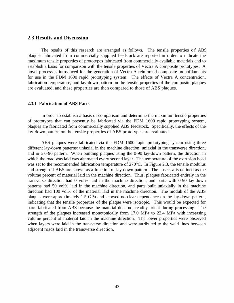
43
2.3 Results and Discussion
The results of this research are arranged as follows. The tensile properties o f ABSplaques fabricated from commercially supplied feedstock are reported in order to indicate themaximum tensile properties of prototypes fabricated from commercially available materials and toestablish a basis for comparison with the tensile properties of Vectra A composite prototypes. Anovel process is introduced for the generation of Vectra A reinforced composite monofilamentsfor use in the FDM 1600 rapid prototyping system. The effects of Vectra A concentration,fabrication temperature, and lay-down pattern on the tensile properties of the composite plaquesare evaluated, and these properties are then compared to those of ABS plaques.
2.3.1 Fabrication of ABS Parts
In order to establish a basis of comparison and determine the maximum tensile propertiesof prototypes that can presently be fabricated via the FDM 1600 rapid prototyping system,plaques are fabricated from commercially supplied ABS feedstock. Specifically, the effects of thelay-down pattern on the tensile properties of ABS prototypes are evaluated.
ABS plaques were fabricated via the FDM 1600 rapid prototyping system using threedifferent lay-down patterns: uniaxial in the machine direction, uniaxial in the transverse direction,and in a 0-90 pattern. When building plaques using the 0-90 lay-down pattern, the direction inwhich the road was laid was alternated every second layer. The temperature of the extrusion headwas set to the recommended fabrication temperature of 270°C. In Figure 2.3, the tensile modulusand strength if ABS are shown as a function of lay-down pattern. The abscissa is defined as thevolume percent of material laid in the machine direction. Thus, plaques fabricated entirely in thetransverse direction had 0 vol% laid in the machine direction, and parts with 0-90 lay-downpatterns had 50 vol% laid in the machine direction, and parts built uniaxially in the machinedirection had 100 vol% of the material laid in the machine direction. The moduli of the ABSplaques were approximately 1.5 GPa and showed no clear dependence on the lay-down pattern,indicating that the tensile properties of the plaque were isotropic. This would be expected forparts fabricated from ABS because the material does not readily orient during processing. Thestrength of the plaques increased monotonically from 17.0 MPa to 22.4 MPa with increasingvolume percent of material laid in the machine direction. The lower properties were observedwhen layers were laid in the transverse direction and were attributed to the weld lines betweenadjacent roads laid in the transverse direction.

44
0.0 0.2 0.4 0.6 0.8 1.01.2
1.3
1.4
1.5
1.6
1.7
1.8
VolumeFraction of Material Laid
Down in the Machine Direction
Tens
ile M
odul
us (G
Pa)
16
18
20
22
24
Figure 3 : Tensile modulus ( ) and strength ( ) of ABS plaques
as a function of lay-down pattern.
Tensile Strength (MPa)

45
In Figures 2.4a and 2.4b cross sections are shown of an ABS plaque fabricated uniaxiallyin the machine direction and of an ABS plaque fabricated in the 0-90 lay-down pattern,respectively. The roads in the uniaxially aligned plaque were packed in a square array, andincomplete packing resulted in voids between the adjacent roads and adjacent layers. These voidswere attributed to premature solidification of the material during fabrication. ABS plaques builtusing the 0-90 lay-down pattern had voids similar to those present in plaques built in a uniaxiallay-down pattern, where the voids were parallel to the roads of that particular layer.

46
a)
b)Figure 2.4 : Micrographs of ABS plaques fabricated via the FDM 1600 rapid prototyping systemusing two different lay-down patterns, a) uniaxial in the machine direction and b) in a 0-90 lay-down pattern.

47
The tensile properties of the ABS plaques were compared to the tensile properties of theABS monofilament feedstock. ABS monofilament used in the FDM 1600 rapid prototypingsystem was found to have a tensile modulus and strength of 2.07 GPa and 25.3 MPa, respectively.The tensile modulus and strength of the ABS plaques fabricated uniaxially in the machinedirection were 1.55 GPa and 22.4 MPa, respectively, which were 75% and 88%, respectively, ofthose of the monofilament. A reason for some of this reduction in properties was the presence ofvoids in the plaques. The void space determined by density measurements was found to beapproximately 13%. Therefore, the tensile properties of the plaques were probably lower than thebulk properties impart due to voids that were formed during part fabrication.
2.3.2 Novel Process for Generation of Composite Feedstock for FDM
In this section, a novel two step process used to generate composite monofilaments foruse in the FDM 1600 rapid prototyping system is described. First the generation of compositestrands from the dual extrusion process is discussed, and then the process used to extrudecomposite monofilaments necessary for the FDM 1600 rapid prototyping system is detailed.Finally, the tensile properties of the composites are evaluated.
In order to develop new materials for use in the FDM 1600 rapid prototyping system thatcould be used to fabricate prototypes with greater mechanical properties and greater functionalitythan those presently available, self-reinforced thermoplastic composite strands were generatedusing a novel dual extrusion process. Vectra A, a TLCP know for its exceptional mechanicalproperties, was used as the reinforcing phase, and PP served as the matrix. Vectra A/PP strandswere spun with 20 wt% and 40 wt% TLCP concentrations, and the moduli of the strands were9.55 GPa and 22.8 GPa, respectively. Further results concerning the properties of these strandsare given elsewhere [7, 8].
Strands from the dual extrusion process were then granulated and re-extruded to formmonofilaments with a diameter of 1.6 mm for use in the FDM 1600 rapid prototyping system. InTable 2.1, the tensile properties of the composite strands and the re-extruded compositemonofilaments are shown. The Vectra A reinforcement in the re-extruded monofilaments resultedin an increase in modulus of approximately 100% over those of neat PP, while having similarstrengths. The tensile properties of the monofilaments, however, were significantly lower thanthose of the strands generated by means of the dual extrusion process. Previous work has shownthat these lower properties were probably due to a reduction in aspect ratio, poor fibrildistribution, and poor fibril alignment [7, 8, 18].

48
Table 2.1: Tensile Properties of PP and PP/Vectra A composites.Tensile Modulus
GPaTensile Strength
MPaPP [9] 0.98
(0.18)23.2(3.9)
Vectra A/PP (20/80 wt%)Strands from the dual extrusion process
9.55(0.55)
116(16)
Vectra A/PP (20/80 wt%)re-extruded monofilaments
1.9(0.14)
25.6(1.3)
Vectra A/PP (40/60 wt%)Strands from the dual extrusion process
22.8(1.6)
321(39)
Vectra A/PP (40/60 wt%)re-extruded monofilaments
2.2(0.13)
21.1(2.3)
(one standard deviation)
2.3.3 Plaque Fabrication via FDM
In this section, processing conditions of composite prototypes generated via the FDM1600 rapid prototyping system are evaluated in order to discern their effects on the tensileproperties of the prototype. First, the dependence of mechanical properties on the processingtemperature during part fabrication is examined for composites with varying Vectra Acompositions, and the tensile properties of the plaques fabricated above and below the meltingpoint of the reinforcement are compared. Second, the tensile properties of the composite partsfabricated at temperatures below the melting point of the reinforcement are correlated with thelay-down pattern. Finally, the tensile properties of parts that were fabricated using neat Vectra Aare related to the lay-down pattern. The effects of these processing conditions on the mechanicalproperties of the composite prototypes are examined in order to fabricate parts with greatermechanical properties giving them greater functionality.
Vectra A/PP monofilaments were used as feedstock to fabricate plaques via FDM, and theeffects of fabrication temperature on the tensile properties of the final part were examined.Monofilaments with 20 wt% and 40 wt% Vectra A were used to build parts with a lay-downpattern aligned uniaxially in the machine direction. In Figure 2.5, the tensile modulus is shown asa function of fabrication temperature for both the 20 wt% and 40 wt% Vectra A composite parts.Plaques with 20 wt% Vectra A reinforcement were fabricated at processing temperatures of190°C, 240°C, and 290°C. The moduli of these plaques were essentially independent ofprocessing temperatures and were approximately 1.6 GPa, even above the melting point of thereinforcement. The 40 wt% Vectra A monofilaments were processed at 240°C and 290°C, andthe moduli of the plaques were 2.7 GPa and 2.4 GPa, respectively. Thus the moduli of thefabricated plaques decreased somewhat when processed above the melting point of thereinforcement. Parts were not fabricated at 190°C for the 40 wt% Vectra A composite because

49
the FDM 1600 rapid prototyping system was unable to generate the pressure required to extrudethe composite.
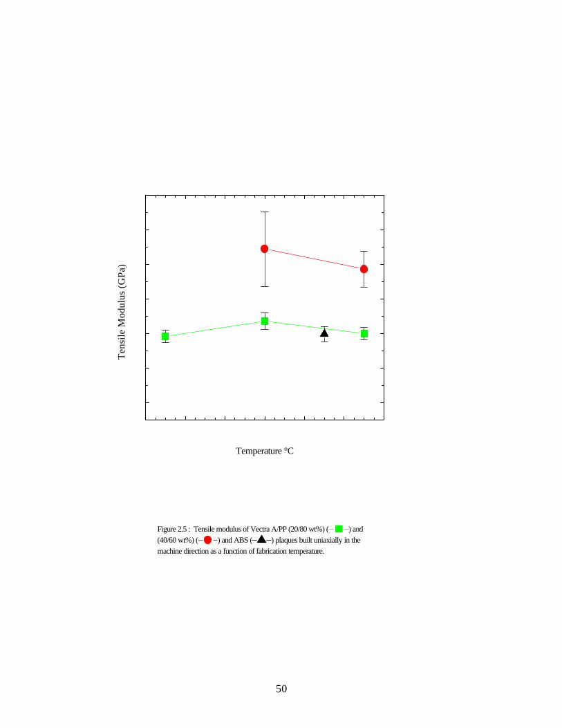
50
Figure 2.5 : Tensile modulus of Vectra A/PP (20/80 wt%) ( ) and (40/60 wt%) ( ) and ABS ( ) plaques built uniaxially in the machine direction as a function of fabrication temperature.
Tens
ile M
odul
us (G
Pa)
Temperature °C

51
In Figure 2.6, the tensile strength is shown as a function of fabrication temperature. Thestrengths of both the 20 wt% and 40 wt% Vectra A reinforced plaques decreased byapproximately one third when processed at 290°C as compared to the strengths of the plaqueswhen processed below the melting point of Vectra A. The strength of the 20 wt% Vectra Aplaques decreased from approximately 33 MPa when fabricated below the melting point of theVectra A to 21 MPa when fabricated above the melting point. Similarly, the strength of the 40wt% Vectra A plaques decreased from 37 MPa when post-processed at 240°C to 25 MPa whenextruded above the melting point of the TLCP. When processed below the melting point ofVectra A, the composite relies on the reinforcement generated in the dual extrusion process.However, when Vectra A/PP composites are processed above the melting point of the TLCP, thereinforcing fibrils are melted and orientation is lost within the TLCP phase. In the melt state, thefibrils form into droplets, and there are minimal extensional forces present in the FDM 1600 rapidprototyping system to develop the fibrilar morphology required for the optimal tensile properties.Thus, tensile properties of Vectra/PP prototypes, where reinforcement was generated in the dualextrusion process, were somewhat better than those where the reinforcement was generatedduring prototype fabrication.

52
Figure 2.6 : Tensile strength of Vectra A/PP (20/80 wt%) ( ) and (40/60 wt%) ( ) and ABS ( ) plaques built uniaxially in the machine direction as a function of fabrication temperature.
Tens
ile S
tren
gth
(MPa
)
Temperature °C

53
The morphology of the prototypes fabricated at temperatures above and below the meltingpoint of Vectra A are compared in Figures 2.7a and 2.7b. The cross sections of Vectra A/PP(40/60 wt%) plaques fabricated at 240°C and 290°C, respectively, are shown here and a clearchange in morphology is evident. When processed at 240°C, below the melting point of theVectra A, the fibrilar morphology of the reinforcement is evident and the fibril diameters rangefrom 1 to 5 microns. The aspect ratio of these fibrils were estimated to be 10 from themicrograph. However, when processed above the melting point of the reinforcement, Vectra Aellipsoids, having major and minor axis ranging from 5 to 150 microns, are evident indicating thatthe TLCP fibrils melted and coalesced. The shear and extensional forces present in the die of theFDM 1600 rapid prototyping system were unable to effectively elongate the Vectra A domains at290°C. Thus, the aspect ratio of the ellipsoids was less than the aspect ratio of the fibrilsgenerated via the dual extrusion system. As indicated by composite theory, the composites withlower aspect ratios have lower moduli with equal volume percent of reinforcement [ 23, 24].Therefore, the composites processed below the melting point of the reinforcement should havehad significantly higher tensile properties than those of the composites processed above themelting point of the TLCP. The reason the properties of the plaques fabricated at temperaturesbelow the melting point of the Vectra A were not similar to those of the composite strandsgenerated by means of the dual extrusion process is probably due to fibril breakage and poor fibrilalignment, during the re-extrusion of the composite strands into monofilaments [7, 8, 18].

54
a)
b)Figure 2.7 : Micrographs of Vectra A/PP (40/60 wt%) plaques fabricated the via FDM 1600rapid prototyping system with a lay-down patterns uniaxial in the machine direction and fabricatedat a processing temperature of a) 240°C and b) 290°C.

55
The mechanical properties of the Vectra A/PP monofilament feedstock were compared tothose of the plaques fabricated via the FDM 1600 rapid prototyping system. The modulus of the40 wt% Vectra A monofilament was measured to be 2.2 GPa. Plaques fabricated uniaxially in themachine direction at 240°C had a modulus of 2.7 GPa. Similarly, the strength of the compositeincreased from 21 MPa to 37 MPa in the fabricated plaque. The modulus of the 20 wt% VectraA monofilaments and plaques was similar before and after fabrication and was approximately 1.8GPa. The strength of the 20 wt% Vectra A monofilaments increased from 26 MPa to 33 MPaafter being fabricated into a plaque. The increase in mechanical properties of the 40 wt% VectraA composite was probably due to a change in alignment of the reinforcing fibrils as a result of theflow kinematics of the extrusion head of the FDM 1600 rapid prototyping system. It has beenshown elsewhere that the tensile properties of post-processed long fiber composite strands arevery sensitive to the flow kinematics of the die [7, 8]. It was shown that a critical L/D wasnecessary in order to obtain the optimal mechanical properties and that the extrusion rate, and diediameter can effect the tensile properties of the extrudate. Vectra A/PP (28/72 wt%) compositestrands from the dual extrusion process were post-processed into monofilaments, and themaximum tensile modulus and strength were 4.0 GPa and 45 MPa, respectively. Thus, higherproperties can be obtained with lower Vectra A concentrations under the proper post-processingconditions [7, 8].
Plaques were fabricated from composite monofilaments using the same three lay-downpatterns used previously to fabricate ABS parts: uniaxial in the machine direction, uniaxial in thetransverse direction, and a 0-90 lay-down pattern. The plaques were fabricated from the VectraA/PP (40/60 wt%) composite monofilaments at 240°C which was the processing temperature thatresulted in the greatest tensile properties for plaques fabricated uniaxially in the machine direction.In Figure 2.8, the mechanical properties are shown as a function of lay-down pattern. It is shownthat both the tensile modulus and strength increased monotonically with the volume percent laid-down in the machine direction. For parts fabricated uniaxially in the transverse direction and partsfabricated uniaxially in the machine direction, the modulus increased from 1.3 GPa to 2.7 GPa,and the strength increased from 10 MPa to 37 MPa. This dependence of mechanical propertieson the lay-down pattern was due to anisotropic reinforcement of the matrix by the TLCP fibrils aswas observed in Figure 2.7a, and this reinforcement was aligned in the direction in which theroads were laid. This was why the greatest mechanical properties were observed in the plaquesfabricated uniaxially in the machine direction. Plaques fabricated uniaxially in the transversedirection had the lowest properties because the reinforcement was aligned orthogonal to themachine direction. Thus, the bulk properties of these plaques were highly dependent on thetensile properties of the matrix. Also, the mechanical properties of a part built in the transversedirection were probably somewhat lower due to weld lines perpendicular to the machine direction.As predicted by composite theory, there was a monotonic increase in mechanical properties withincreasing volume fraction laid-down in the machine direction [24]. Therefore, using compositetheory, the mechanical properties of the final part can be engineered to match the requirements ofthe proposed prototype by adjusting the lay-down pattern.

56
Figure 2.8: Tensile modulus ( ) and strength ( ) of Vectra A/PP (40/60 wt %) composite plaques fabricated via FDM as a function of volume fraction laid in the machine direction processed at 240°C.
Volume Fraction of Material LaidDown in the Machine Direction
Tens
ile M
odul
us (G
Pa) Tensile Strength (M
Pa)

57
In order to fabricate prototypes with even greater tensile properties than those of theVectra A composites, neat Vectra A plaques were fabricated via the FDM 1600 rapid prototypingsystem using three different lay-down patterns: uniaxial in the machine direction, uniaxial in thetransverse direction, and in a 0-90 pattern. Vectra A was processed at 300°C, the maximumtemperature of the FDM 1600 rapid prototyping system, which was below the temperaturenecessary to melt all of the residual crystallites [13]. The tensile properties of the plaques areshow in Figure 2.9 as a function of lay-down pattern. Both the tensile modulus and the strengthwere dependent of the lay-down pattern. The tensile moduli of the plaques with 0%, 50 %, and100% of the material laid in the machine direction were 1.3 GPa, 6.5 GPa, and 6.1 GPa,respectively, and the strengths were 9 MPa, 66 MPa, and 87 MPa, respectively. The modulus ofthe samples with 50% of the material laid in the machine direction were greater than those of thesamples with 100% of the material laid in the machine direction. Hence, tensile properties of theneat Vectra A parts did not increase linearly with volume percent of TLCP laid in the machinedirection as predicted by composite theory and as seen in Vectra A/PP plaques. This deviationfrom the properties predicted by composite theory was attributed to poor adhesion betweenadjacent layers and adjacent roads in the plaque. It was observed that roads and layersdelaminated in the neat Vectra A plaque. This was probably a result of the high solidificationtemperature of the Vectra A when compared to both PP and ABS. After the road was laid down,the Vectra A probably quenched to the solid state before adjacent roads and layers could adhere.If the Vectra A could have been processed above 320°C, the time from when the road was laiduntil the time when the material was no longer deformable, adhesion probably would haveincreased, due to the supercooling nature of Vectra A [25, 26]. Delamination was not evidentwith plaques fabricated from the Vectra A/PP, and micrographs indicate that this was due to goodadhesion between the PP surface of adjacent roads.

58
Figure 2.9: Tensile modulus ( ) and strength ( ) of neat Vectra A plaques fabricated via FDM as a function of volume fraction laid in the machine direction processed at 240°C.
Volume Fraction of Material LaidDown in the Machine Direction
Tens
ile M
odul
us (G
Pa)
Tensile Strength (MPa)

59
The tensile properties of pure Vectra A plaques fabricated via FDM were compared to themaximum properties obtained for Vectra A. In order to obtain the maximum tensile properties ofTLCP parts, strong extensional forces must be used to obtain high degrees of molecularorientation in the TLCP, and these forces are present during fiber spinning [ 5, 6]. The maximumreported modulus for pure Vectra A strands was 69 GPa while the modulus of injection moldedneat Vectra A plaques was determined to be 14 GPa in the machine direction [ 7, 8]. Themaximum modulus of neat Vectra A prototypes fabricated by FDM was approximately 6 GPa andobtained for samples fabricated using the 0-90 lay-down pattern [7, 8]. Therefore, the propertiesof fabricated plaques were low compared to those of Vectra A processed using other processingtechniques. These results indicate that with the proper flow kinetics and with the increasedadhesion between adjacent roads there is potential for the tensile properties of pure Vectra Aprototypes fabricated by FDM to approach those of injected molded samples.
2.4 Conclusions
Plaques were fabricated from Vectra A/PP composites and neat Vectra A monofilamentsvia FDM. Because the composite material flowed readily through the 0.6 mm die on the FDMsystem during part fabrication with relatively low torque when compared to those ABS, it isbelieved that parts could be similarly fabricated with a 0.3 mm die. The tensile modulus of VectraA/PP (40/60 wt%) composite plaques were approximately 100% greater than those of ABS andapproximately 150% greater than those of pure PP, and these properties could probably beincreased if long fiber reinforced composite monofilaments were used as feedstock. The tensilemodulus and strength of the neat Vectra A plaques were approximately four times those of ABS.Therefore, prototypes fabricated with these materials would have greater functionality than thosefabricated with ABS.
Due to the anisotropic mechanical properties present in TLCPs and TLCP composites, thelay-down pattern affected the properties of the final part. It was found that the tensile propertiesof Vectra A/PP composites increased monotonically with roads laid in the machine direction.Thus, the final mechanical properties of a prototype can be tailored to a specific application byadjusting the lay-down pattern, increasing the functionality of the prototype. The mechanicalproperties of neat Vectra A prototypes with varying lay-down patterns did not agree with the ruleof mixtures. This was due to delamination of the plaque as a result of poor adhesion betweenadjacent roads and layers.
2.5 Acknowledgments
This research was supported by the Army Research Office (Grant No. DAAH04-94-G-0282); the Naval Surface Warfare Center, Dahlgren Division and Armstrong Laboratory, Brooks

60
AFB under contract N60921-89-D-A239, Order 0059; and Stratasys, Inc. Also, the authorswould like to thank Prof. G. L. Wilkes for the use of the SEM and M. A. McLeod for operatingit.
1 A. I. Isayev, in Liquid-Crystalline Polymer Systems Technological Advances, Ed. A. I.
Isayev, T. Kyu, and S. Z. D. Cheng, American Chemical Society, Washington D. C. 1996.2 D. G. Baird, in Polymeric Materials Encyclopedia, Ed. J. C. Salamone, CRC Press, Boca
Raton 1996.3 A. A. Handlos and D. G. Baird, J. Macromol. Sci.-Rev. in Macromol. Chem. and Phy.,
C35, 183 (1995).4 K. G. Blizard and D. G. Baird, Polym. Eng. and Sci., 27, 653 (1987).5 G. G. Viola, D. G. Baird, and G. L. Wilkes, Polym. Eng. and Sci., 25, 888 (1985).6 A. Kohli, N. Chung, and R. A. Weiss, Polym. Eng. and Sci., 29, 573 (1985).7 R. W. Gray IV, M. S. Thesis, Virginia Polytechnic Institute and State University (1997).8 R. W. Gray IV, D. G. Baird, and J. H. Bøhn, Polym. Comp., in preparation (1997).9 E. A. Sabol, A. A. Handlos, and D. G. Baird, Polym. Comp., 16, 330 (1995).10 Himont Profax Bulletin AP-002, Himont U. S. A., Inc. (1990).11 D. G. Baird and A. Sukhadia, U.S. Patent 5,225,488 (1993).12 E. A. Sabol, M. S. Thesis, Virginia Polytechnic Institute and State University (1994).13 S. M. Guskey and H. H. Winter, J. Rheol., 35, 1191 (1991).14 C. R. Robertson, M. S. Thesis, Virginia Polytechnic Institute and State University (1995).15 C. G. Robertson and D. G. Baird, Intern. Polym. Proc., in press (1997).16 R. K. Krishnaswamy and D.G. Baird, Polym. Comp., in press (1997).17 C. G. Robertson, J. P. de Souza, and D. G. Baird, Recent Advances in Liquid Crystalline
Polymers, A. I. Isayev, T. Kyu, and S. Z. D. Cheng eds., ACS Books, Washington D. C.(1996).
18 A. A. Handlos and D. G. Baird, Intern. Polym. Proc., XI, 82 (1996).19 A. A. Handlos and D. G. Baird, Polym. Comp., 17, 73 (1996).20 A. A. Handlos and D. G. Baird, Polym. Eng. and Sci., 36, 378 (1996).21 M. Y. Cao and B. Wunderlich, J. Polym. Sci.: Polym. Phy. Ed., 23, 521 (1985).22 Amoco Polypropylene Homopolymers Bulletin PP-8n, Amoco Polymers, Inc. (1996).23 G. Crevecoeur and G. Groeninckx, Polym. Eng. and Sci., 30, 52 (1990).24 J. C. Halpin, Polym. Eng. and Sci., 16, 344 (1976).25 D. Done and D. G. Baird, Polym. Eng. And Sci., 27, 816 (1987).26 D. Done and D. G. Baird, Polym. Eng. And Sci., 30, 989 (1990).

61
3.0 Effects of Processing Conditions on Long FiberComposites
This chapter focuses on the first objective of this thesis. The effects of thermal and shearhistory present during FDM are examined on the tensile properties of long fiber composite strandsgenerated using the dual extrusion process. This chapter is organized as a manuscript and will besubmitted to Polymer Composites.

62
Effects of Processing Conditions on Thermoplastic Composites Reinforced with Long FiberThermotropic Liquid Crystalline Polymers for Fused Deposition Modeling.
R. W. Gray IV, D. G. Baird, and J. H. BøhnDepartment of Chemical Engineering,
Department of Mechanical Engineering,Rapid Prototyping Laboratory, and
Polymer Materials and Interfaces LaboratoryVirginia Polytechnic Institute and State University
Blacksburg, VA 24061-0211
AbstractThis work is concerned with preliminary studies on developing thermoplastic composite materialssuitable for use in fused deposition modeling (FDM). Polypropylene (PP) strands reinforced withthermotropic liquid crystalline polymer (TLCP) fibrils were generated in a novel dual extruderprocess. The process allowed the reinforcement of PP with a melting point ( Tm) equal to 165°Cwith continuous fibrils of a high melting (283°C) TLCP (Vectra A950). The strands were then re-extruded in a capillary rheometer forming monofilaments to simulate piston actuated FDM. Theeffects of the thermal and deformation histories on the mechanical properties of the re-extrudedstrands were evaluated. It was found that tensile properties of the strands improved with drawratio and that the maximum modulus of the composite strands was similar to that predicted bycomposite theory. Strands were consolidated uniaxially via compression molding at temperaturesjust above the melting point of the matrix in order to determine the effect of thermal history. Thisresulted in approximately a 20% reduction in tensile modulus relative to the modulus of thestrands. Monofilaments were extruded from a capillary rheometer in which long fiber strandswere used as feedstock in order to study the effects of deformation history on the tensileproperties. It was found that the tensile properties of the monofilaments were dependent oncapillary diameter, capillary L/D, and apparent shear rate due to fibril alignment.

63
3.1 Introduction
Fused deposition modeling (FDM) is one of several different rapid prototyping fabricationtechnologies that are being studied at present. The FDM 1600 rapid prototyping system byStratasys, Inc. consists of an extrusion system that is able to precisely control where the extrudateis laid in three dimensional space in order to build a prototype with a complex geometry. Usingthis system, a part is fabricated in layers, where a layer is built by extruding a small bead ofmaterial, or road, in a particular lay-down pattern, such that the layer is covered with adjacentroads. After a layer is completed, the height of the extrusion head is increased and subsequentlayers are built to construct the part.
At present, only a few polymeric materials with limited mechanical properties are used inthis style of rapid prototyping system. Many of the prototypes fabricated can only serve asgeometric replicas of the proposed production part because of the inherently poor mechanicalproperties. The materials that are commercially available for the FDM 1600 rapid prototypingsystem are acrylonitrile butadiene styrene copolymer (ABS), a nylon copolymer, and investmentcasting wax. Of the three commercially available materials, ABS has the highest tensile modulusand strength, and the properties of prototypes fabricated using ABS have been determined to be1.5 GPa and 22 MPa, respectively [1]. Therefore, there is interest in developing materials thatcan be used to fabricate prototypes with higher mechanical properties which give the parts greaterfunctionality.
Thermotropic liquid crystalline polymers (TLCPs) are a novel class of material that havepotential for use in FDM applications for two reasons. First, it has been observed that TLCPfibers have excellent tensile properties with moduli ranging from 50 GPa to 100 GPa in melt-spunfibers. Second, it has also been found that due to their excellent tensile properties and due to theirfibril forming nature, TLCPs can be used to reinforce thermoplastics [ 2 - 4]. The diameter of thereinforcing TLCP fibrils is typically one order of magnitude smaller than that of typical glass andcarbon fiber. However, it may be not possible to extrude glass and carbon fibers through the diehead and still maintain high aspect ratio fiber (i. e. L/D > 100) due to the small diameter capillarydie (0.3 mm) used in order to fabricate dimensionally precise prototypes.
It would be desirable to use TLCP/thermoplastic blends to form composites on an in situbasis during prototype fabrication. However, there are two disadvantages with this approach.First, there is potential for degradation of the matrix. Most commercial TLCPs are processed attemperatures near or above the degradation temperature of most commodity resins. Vectra B , forexample, has a melting point of 280°C and processes at approximately 320°C [ 5]. PP can beprocessed above 260°C, but this can lead to significant degradation [6]. Engineeringthermoplastics can be used as matrices, but they are generally much more expensive. Second, inthe case of the FDM 1600 extrusion head, the flow field present during fabrication is shear flow,which is known not to be as effective in forming highly oriented fibrils as extensional flow [ 7,8].

64
Therefore, tensile properties of in situ reinforced prototypes are expected to be similar to those ofextruded TLCP reinforced composites and less than those of injection molded TLCP reinforcedcomposite because some extensional stresses are present during injection molding.
In order to overcome the problems associated with processing the blends directly, theformation of pregenerated microfibrils was considered using a novel dual extrusion process [ 5, 9,10]. In the dual extrusion process, the thermoplastic and TLCP are plasticated in separateextruders so that independent thermal histories are imposed to the two materials. TLCP is heatedto sufficiently high temperatures to fully melt all of the crystallites. For example, the melting pointof Vectra A is 283ºC, but it needs to be heated to 320ºC in order to fully melt all the residualcrystallites [11]. Vectra A is then supercooled to the temperature at which the matrix isprocessed and, using a multiple-port injection nozzle, is then injected into the matrix stream whichresults in continuous TLCP streams encapsulated within the matrix. The melt is passed through aseries of static mixers which serve to divide the TLCP streams, before being extruded through acapillary die and drawn in the spinline to high draw ratios in order to achieve high levels ofmolecular orientation in the TLCP fibrils.
There are several advantages of the dual extrusion process over generating TLCP fibrils insitu during FDM. Processing the TLCP in a separate extruder minimizes degradation of thematrix because the matrix is not exposed to the high temperatures that are necessary to fully meltthe TLCP. The TLCP is supercooled, allowing it to be injected into the matrix. However, somedegradation of the matrix is possible upon injection of the TLCP into the matrix. The dualextrusion process does not rely on droplet deformation because the multiple-port injection nozzleintroduces continuous TLCP streams into the matrix, resulting in high aspect ratio fibrils. Finally,the composite strands can be post-processed above the melting point of the matrix and below themelting point of the TLCP using a variety of conventional processing techniques (e.g., FDM)which allow for the retention of the TLCP reinforcing fibrils generated during the dual extrusionprocess in the final part [5, 10, 12 - 21].
Post-processing of composite strands above the melting temperature of the matrix andbelow the melting temperature of the TLCP is critical to transforming the composite strands intofinal parts while retaining the reinforcement achieved in the original strands. The strands havebeen post-processed using conventional processing techniques: compression molding, injectionmolding, film extrusion, and blow molding. Composite strands have been uniaxially compressionmolded, and tensile properties of the consolidated plaques have been shown to agree with thosepredicted by composite theory [5, 10, 12, 14, 16]. The mechanical properties of films and bottleswere lower than those calculated by composite theory, but the properties had greater isotropy inthe plane than those of parts where the reinforcement was generated in situ [ 18, 19]. Mixedresults have been observed for the mechanical properties of injection molded plaques whencompared to those predicted by composite theory [17, 20].
The deviations from composite theory were attributed to three possibilities. The aspectratio of the reinforcement may have been less than 100 due to agglomeration of the fibrils or fibril

65
breakage in the screw. Poor fibril distribution was observed in the plaques and may have been theresult of agglomeration of the fibrils or insufficient mixing. There may have been a loss inmolecular orientation in the TLCP fibrils [17].
Composite strands generated from the dual extrusion system have been used in the FDM1600 rapid prototyping system in order to fabricate short fiber reinforced composite prototypeswith mechanical properties greater than those of the three commercially available materials for thesystem [12, 21]. Vectra A/polypropylene (PP) strands with 20 wt% and 40 wt% Vectra Agenerated by means of the dual extrusion system were granulated to lengths less than 6 mm longbefore being re-extruded into monofilaments for use as feedstock in the FDM 1600 rapidprototyping system. The tensile moduli of Vectra A/PP (40/60 wt%) composite prototypes wereshown to surpass those of prototypes fabricated from ABS by nearly 100% and to surpass thoseof PP by 150%. However, the tensile properties of the composite prototypes were lower thanthose predicted by composite theory. The reasons for the deviation from ideality were attributedto decreased fibril alignment and decreased aspect ratio due to fibril breakage. It was shown thatby taking advantage of the isotropic tensile properties that resulted in the Vectra A/PP beadsextruded from the FDM 1600 system, the properties of the composite prototypes could beengineered for specific applications by adjusting the lay-down pattern [12, 21].
The purpose of this work is to demonstrate a new process where TLCP long fiberreinforced monofilaments were generated for use in FDM applications, and to evaluate the effectsof processing on the tensile properties of extruded strands. Due to less than optimal tensileproperties of short fiber reinforced prototypes discussed above, preliminary studies concernedwith TLCP long fiber reinforced composites suitable for use in plunger driven FDM are presented.The composite strands generated from the dual extrusion system were re-extruded attemperatures just above the melting point of the matrix in order to retain the reinforcing fibrils andexcellent mechanical properties that were generated via the dual extrusion system. The effects ofthermal history on the tensile properties and on the molecular orientation of the reinforcement arestudied on the composite strands in a shearfree environment. Also, the effects of temperaturecoupled with shear flow on the tensile properties of long fiber reinforced composites aredetermined using a plunger actuated extrusion process. The effects of the post-processing stepson the tensile properties are determined by comparing those of the post-processed composite tothose of the composite strands from the dual extrusion process.
3.2 Experimental
3.2.1 Materials
The TLCP used was Vectra A950 (Hoechst Celanese). It is a random copolyester basedon hydrobenzoic acid (73% mole) and 2-hydroxy-6-napthoic acid (27% mole). It has a glasstransition temperature of 108°C and a melting point of 283°C [22]. However, Vectra A needs to

66
be heated to 320°C to melt out all of the residual crystallites [11]. Prior to spinning, the Vectra Awas dried at least 18 hours in a forced convection oven set at 150°C. The matrix material usedwas the 4018 grade of Amoco polypropylene (PP). It has a melting point of 160ºC and a meltflow index (MFI) of 13.5 [23].
3.2.2 Spinning of TLCP/PP Composite Strands
The novel dual extrusion process was used to spin self-reinforced composite fibers. Thedual extrusion process has been described in detail elsewhere [5, 9, 10]. Vectra A and PP wereplasticated separately in two Killion KL-100 extruders (1 inch single screw extruders withL/D=24) where the metering zone temperatures of the TLCP and PP extruders were set at 325°Cand 245°C, respectively. The TLCP mass flow rate was controlled by metering it into the PPstream using a Zenith gear pump (model number 6135419-001 and 1.725 cc/rev). The TLCP wasinjected into the matrix as continuous streams via a multiple-port injection nozzle. The meltpassed through a series of three Kenics and four Koch mixing elements that served to split theTLCP streams. The melt was then extruded through a capillary die with a diameter of 1.8 mmand a L/D of 1. The filaments were drawn through a 3.7 m long drawing chimney before beingquenched in water and taken up on a constant speed godet. The draw ratio, estimated as the ratioof cross-sectional area of the capillary to that of the fiber, was greater than 70. The compositionwas determined from the total mass flow rate and the Vectra A mass flow rate.
Pure Vectra A strands were spun using a Killion KL-100 extruder. The metering zonetemperature was set at 325°C, and the die diameter was 1.6 mm with a L/D of 4. The extrudatewas drawn through a 3.7 m chimney and was taken up on a constant speed godet in a mannersimilar to that of the dual extrusion process, and the draw ratios were estimated to be greater than100.
3.2.3 Compression Molding
The composite strands produced by means of the dual extrusion process wereconsolidated uniaxially using a Carver hot press (model number 2696) with the temperature set at180°C. The strands were laid into a preheated picture frame mold (89 mm by 89 mm) in auniaxial fashion, and it was placed in the press for 6 minutes and subjected to 1 MPa of pressure.The sample was then quenched in a water-cooled press where the cooling rate was determined tobe approximately 20°C per minute.

67
3.2.4 Post-Processing Extrusion from the Capillary Rheometer
Composite strands from the dual extrusion process were re-extruded through a capillarydie using an Instron Capillary Rheometer (Model 3211). Before being fed into the rheometerbarrel, strands were compression molded into cylindrical cartridges that had diameters slightlysmaller than that of the barrel. The cartridges were consolidated by uniaxially aligning strandsthat were approximately 10 cm long in a mold that was 10.5 cm long, and they were compressionmolded at 180°C using the afore-mentioned procedure for uniaxially aligned plaques. After thestrands were consolidated, the composite was quenched in a water-cooled press with anapproximate cooling rate of 20°C per minute. The TLCP reinforcement within the cartridges wasbelieved to be continuous, and thus, the aspect ratio of the reinforcement was greater than 100.
The composite cartridges were extruded in a capillary rheometer using the followingapproach. First, the capillary and barrel temperature of the rheometer was set at temperatures ofeither 180°C, 210°C, or 240°C. A cartridge was then loaded into the barrel of the capillaryrheometer and held at the temperature of the capillary for 6 minutes. The slug containing theunmelted TLCP fibrils was extruded at rates of 0.2 cm 3/min. to 20 cm3/min. through capillaries ofvarious L/D ratios as listed in Table 3.1 with no draw imposed. The entry angle of the capillarieswas 90° while the diameters were 1.8 mm and 0.7 mm.

68
Table 3.1 : The dimensions of the capillary dies used to post-process the long fibercomposites through the capillary rheometer are shown.
CapillaryDie Number
Diameter L/D
1 1.8 mm 7.82 1.8 mm 14.2
3 0.7 mm 12.54 0.7 mm 18.55 0.7 mm 37.16 0.7 mm 110
In order to differentiate between composites samples extruded from the dual extruderassembly and those extruded from the capillary rheometer, the former will be referred to asstrands and the latter as monofilaments. In the former case, the TLCP fibrils are basicallycontinuous and have not been subjected to an additional thermal or deformation history. In thelatter case, the initial strands have been subjected to a thermal history during compression moldingand then to an additional thermal history in the barrel of the capillary rheometer as wellas adeformation history.
3.2.5 Mechanical Properties
The tensile modulus and strength were measured using an Instron Mechanical Tester(model 4204) following the ASTM standard D 638-87b. The test samples were approximately 8mm wide, 1.7 mm thick, and 30.5 mm in length. The load was measured with a 5 kN load cell,and the strain was measured using an extensiometer (Instron model 2630-25), while the crosshead speed was kept at 1.27 mm/min.

69
The modulus and strength of the strands and composite monofilaments were alsodetermined (ASTM D 3376-75). The ends of both the strands and the monofilaments werewrapped with masking tape to ensure uniform gripping of the sample. The length of the strandsused in testing was approximately 280 mm long, while the composite monofilaments generatedfrom the capillary rheometer were approximately 180 mm long. A 1 kN load cell was used tomeasure the load as a function of displacement, while the cross head speed was kept at 1.27mm/min. For all tests, the average and the standard deviation were calculated from at least fivesamples, and data points greater than 2 standard deviations from the mean were removed.
3.2.6 Wide Angle X-ray Scattering
A Philips Table-Top X-Ray Generator model PW 1720 with a standard vacuum-sealedStatton Camera was used to produce X-ray diffraction patterns. Strands and plaques wereexposed to CuKα radiation with a wave length of 1.54 Å for 6 hours. The distance from thesample to the film was 7.8 cm.
3.2.7 Scanning Electron Microscope
Cross sections of composite fibers, monofilaments, and plaques were fractured after beingplaced in liquid nitrogen for 5 minutes. The surfaces were gold coated using a n Edwards sputtercoater (model S150B). Micrographs were then taken using a Cambridge Stereoscan Model 100scanning electron microscope operating at 20 kV.
3.3 Results and Discussion
The results of this research are arranged as follows. The tensile properties of the VectraA/PP strands generated from the dual extrusion system are reported in order to compareexperimentally obtained values with those of composite theory and in order to provide a basis ofcomparison for the tensile properties of the post-processed composite. Thus, the effects of thepost-processing step on the tensile properties can be determined. The effects of post-processingon the composite strands are divided into two sections. First, the effects of thermal history in theabsence of a flow field on the tensile properties during post-processing are presented. Second,the effects of ram extrusion through a capillary die on the tensile properties are investigated, whilevarying capillary L/D, capillary diameter, extrusion rate, and post-processing temperature in orderto simulate a FDM system for long fiber composite fabrication.

70
3.3.1 Fiber Spinning using the Dual Extrusion Process
In this section the mechanical properties of the composite strands are evaluated. Thisprovides a basis of comparison for the tensile properties of the post-processed compositesallowing for the determination of the effects of the post-processing steps on the tensile properties.First, the effects of draw ratio on the mechanical properties of Vectra A/PP strands that werespun using the dual extrusion process are addressed. Second, to determine the effectiveness ofthe dual extrusion system at developing the optimal mechanical properties of the compositestrands, properties are compared to the rule of mixtures.
In Figure 3.1, the tensile modulus is shown as a function of draw ratio of Vectra A/PP(28/72 wt%) strands that were spun using the dual extrusion process through 1.8 mm capillarywith an L/D of 1. The tensile properties of composite strands increased with increasing drawratio. Between the draw ratios of 12 and 25, the tensile modulus increased from 6 GPa to 9 GPa.The modulus of the strands continued to increase even at very high draw ratios. At draw ratiosgreater than 100, the modulus increased only slightly, and at the highest attainable draw ratio themodulus was found to be 15 GPa. The strength also increased with draw ratio in a similar fashionreaching an asymptotic value of 160 MPa at high draw ratios. This increase in tensile propertieswas probably due to greater orientation as a result of increased strain and strain rates in thespinline at higher draw ratios [5, 15].

71
0 50 100 150 2000
10
20
Figure 3.1 : Tensile modulus ( ) of Vectra A/PP (28/72 wt%) strands
spun using the dual extrusion system as a function of draw ratio.
The capillary die diameter was 1.8 mm, and the L/D was 1.
Tens
ile M
odul
us (G
Pa)
Draw Ratio

72
Vectra A/PP composite strands of three composition levels (20, 28, and 40 wt% VectraA) were spun using the dual extrusion process, and the tensile properties of strands werecompared to those based on composite theory. In Figure 3.2, the modulus of Vectra A/PPstrands is shown as a function of composition, and the moduli increased with increasing Vectra Aconcentration. The moduli were compared to predictions made using the Halpin-Tsai equation,which simplifies to the rule of mixtures for reinforcements for aspect ratios greater than 100 [ 24,25]. The rule of mixtures is
E E Ec m m f f= +Φ Φ (1)
for uniaxially oriented samples, where Ec, Em, and Ef are the moduli of the composite fiber, the PPmatrix, and the Vectra A reinforcement, respectively, and Φm and Φf are the volume fractions ofthe matrix and the reinforcement, respectively. The E f of the reinforcing fibrils within thecomposite strands was calculated using the rule of mixtures. The E m of the PP was taken as 1GPa, and the volume fraction was calculated from known weight fractions [ 5]. For 20 wt% (14vol%), 28 wt% (19 vol%), and 40 wt% (30 vol%) Vectra A composite strands, the moduli of thereinforcing phase of the composite strands, E f, were calculated to be 63 GPa, 73 GPa, and 74GPa, respectively. Neat Vectra A strands were spun, and the modulus was found to beapproximately 69 GPa at draw ratios in excess of 100. This value is comparable to 65 GPa thathas been reported elsewhere for neat Vectra A strands [4]. Therefore, the calculated moduli forthe Vectra A reinforcing fibrils within the composite strands were very close to the maximumattainable modulus measured for pure Vectra A, indicating excellent agreement between modulicalculated using the rule of mixtures and those obtained experimentally for the neat strands. Thisagreement with the rule of mixtures has also been observed with Vectra B/PP (30/70) strandsspun using the dual extrusion process when drawn to moderate draw ratios (70-80) [ 5, 10].When spun at draw ratios in excess of 100, however, Nylon-11/HX8000 (13, 22, and 35 wt%)and Vectra B/PP (50/50) strands generated by means of the dual extrusion system had tensileproperties greater than those predicted by composite theory [12 - 15]. These synergisticproperties were attributed to greater TLCP orientation, which was obtained by encapsulating theTLCP fibrils within the matrix. It was speculated that the thermal insulation prevented prematuresolidification of the TLCP in the spinline, and this may have enhanced molecular orientationbecause of the ability to impart higher extensional strains to the TLCP fibrils [ 12 - 15]. Thoughsimilar synergistic properties were not observed with the Vectra A/PP composite strands beinginvestigated, the use of others processing conditions (e.g., higher melt temperature for the VectraA) may have resulted in synergistic effects in these strands.

73
0.0 0.2 0.4 0.6 0.8 1.00
20
40
60
80
0
20
40
60
80
Ec = E
m Φ
m + E
f Φ
f
Figure 3.2 : Tensile modulus ( ) of Vectra A/PP composite strands
as a function of Vectra A volume fraction and as compared to the "rule
of mixtures" ( ) where the modulus of neat Vectra A was 69 GPa.
Experimential Values
Rule of Mixtures
Tens
ile M
odul
us (G
Pa)
Volume Fraction of Vectra A in
Vectra A/PP Composite Strands

74
3.3.2 The Effects of Post-Processing Thermal History
In this section, the effects of thermal history in the absence of a flow field on mechanicalproperties of composite strands from the dual extrusion process are discussed. This is done inorder to understand more clearly the reasons as to why previously reported experimentalproperties of composite prototypes fabricated by FDM were not similar to theoretical predictions[12, 21]. Also in this section, a possible reason for an observed decrease in properties as a resultof an imposed post-processing thermal history is identified.
In order to isolate the effects of thermal history during post-processing, strands from thedual extrusion process were consolidated uniaxially into plaques using compression molding at180°C. The mechanical properties of the plaques were then compared to those of the strands.The moduli of the 20 wt% and 40 wt% Vectra A uniaxial plaques were 7.7 GPa and 17.3 GPa,respectively. However, the moduli of the strands were 9.6 GPa and 22.8 GPa, respectively. Thisapproximate 20% reduction in moduli for both samples was probably associated with the TLCPreinforcement. From micrographs, not shown here it was observed that the reduction in tensileproperties of the strands was not due to a change in fibril alignment after consolidation or due tofibril deformation [12].
In order to determine if the decrease in tensile properties of the composites was from areduction in tensile properties of Vectra A fibrils, the effects of post-processing thermal history onthe neat TLCP strands were evaluated. In order to emulate the same thermal history on neatVectra A strands that was present during Vectra A/PP strand consolidation, neat TLCP strandswere annealed in a convection oven for 10 minutes and for 2 hours at 180°C, which was the sametemperature used to consolidate the composite strands. Before annealing the Vectra A strands,their modulus was 69 GPa. After 10 minutes and 2 hours the moduli of the strands were 61 GPaand 60 GPa, respectively. Annealing of the strands resulted in approximately a 12% loss inmoduli. Thus, the loss in modulus during the consolidation of the composite strands was mostlikely due to the loss in modulus of Vectra A fibrils.
The orientation of the TLCP was examined because the tensile properties of TLCPreinforced composites are dependent to a great extent on the orientation of the TLCP [ 26]. Wideangle X-ray scattering (WAXS) patterns were employed in order to determine the orientation ofthe crystalline region of the Vectra A. WAXS patterns of Vectra A/PP strands before and afterconsolidation were examined, in order to determine the effects of compression molding on theorientation of the TLCP. In order to identify WAXS reflections caused by Vectra A from thosecaused by PP, WAXS patterns of neat Vectra A were examined. The d spacing of the Vectra Areflections was determined to be 6.9 Å, 4.6 Å, and 3.4 Å, which was also observed by Winter andLin [27]. Also, an increase in the intensity of the scattering was observed along the equatorialaxis indicating that neat Vectra A was oriented parallel to the drawing direction of the strand. InFigure 3.3a, a WAXS pattern of Vectra A/PP (20/80 wt%) composite strands from the dualextrusion process is presented, and it contains several features. The two concentric circlesrepresent reflections which resulted from the crystalline regions of the PP. Focusing on the

75
Vectra A reflection representing a d spacing of 4.6 Å, the scattering angle of the reflectionindicated that the reinforcement was highly oriented in the direction parallel to the spinline. InFigure 3.3b, a WAXS pattern of Vectra A/PP (20/80 wt%) composite strands after beingconsolidated uniaxially into a plaque is shown, and several features are evident. In this pattern,the four concentric circular reflections resulted from the crystalline regions of the PP. Againfocusing on the Vectra A reflection representing a d spacing of 4.6 Å, the scattering angleindicated that Vectra A was highly oriented in the machine direction of the plaque. The scatteringangle of this reflection could not be measured accurately from either of the two WAXS patternsdue to the diffuse nature of the reflection. The scattering angle of the Vectra A reflection fromthe consolidated plaques, however, was observed to be broader than that of the Vectra Areflection from the composite strands generated using the dual extrusion process.

76
a)
b)
Figure 3.3 : WAXS patterns of a) Vectra A/PP (20/80 wt%) strands from the dual extrusionprocess and of b) a Vectra A/PP (20/80 wt%) consolidated plaque composed of uniaxially alignedstrands from the dual extrusion process.

77
The increase in the scattering of the Vectra A reflection representing a d spacing of 4.6 Åin the consolidated composite compared to that of the composite strands could be attributed toseveral reasons. One possible reason for the difference in scattering angle between strands andthe consolidated plaque could be due to a decrease in molecular orientation of the TLCP. Thereflections indicate the orientation of the crystalline planes which probably did not melt during theconsolidation of the strands. The orientation of the crystalline planes may have changed due tomobility in the mesophase during consolidation which would result in a change in the scatteringangle. Another possible reason is that during consolidation the fibers may have been slightlymisaligned, which would result in a decrease in orientation of the crystalline regions within theplaque. Both reasons would have resulted in an apparent decrease in mechanical properties of theconsolidated plaque compared to those of the composite strands. Finally, variations in thethickness of the two samples may have resulted in different scattering angles. The thickness of thetest plaque was easily measurable, but the thickness of the bundle of fibers that was used fortesting varied across the sample due to voids present between adjacent fibers.
3.3.3 Shear History
The effects of deformation during processing on the tensile properties of the compositewere examined under conditions similar to those found in plunger actuated FDM. In order todetermine the effects of post-processing flow history on the Vectra A/PP long fiber compositestrands, they were re-extruded in a capillary rheometer at temperatures (190°C, 210°C, and240°C) just above the melting point of the matrix but below the melting point of Vectra A. Thiswas done to simulate the post-processing of long fiber composites via FDM using a plungeractuated extrusion process. This section evaluates the effects of capillary L/D, capillary diameter,extrusion rate, and processing temperature on the mechanical properties of the monofilament.
In Figure 3.4, the tensile modulus and strength of Vectra A/PP monofilaments extrudedthrough a capillary is shown as a function of L/D. Cartridges of Vectra A/PP (28/72 wt%) withcontinuous TLCP fibrils were extruded through dies 3 - 6 (see Table 3.1) at an apparent shearrate of 67 sec-1 and at a constant temperature of 180°C. The entry angle of all of the capillariesused in this research was 90°. The results in Figure 3.4 indicate that a critical L/D ofapproximately 18 is needed in order to obtain the maximum tensile modulus and strength of 3.5GPa and 44 MPa, respectively. The tensile properties of the monofilaments decreased slightlywhen processed through capillaries with a L/D greater than that of the critical L/D. A critical L/Dwas similarly observed with capillaries having a diameter of 1.8 mm.

78
0 20 40 60 80 100 1202.0
2.5
3.0
3.5
4.0
L/D
Tens
lie M
odul
us (G
Pa)
20
25
30
35
40
45
Figure 3.4 : Tensile modulus ( ) and strength ( ) of Vectra A/PP (28/72 wt%) composite monofilaments as a function of L/D extruded through a 0.7 mm diameter capillary at 180 °C and at an apparent shear rate of 67 sec-1.
Tenslie Strength (MPa)

79
In Figure 3.5a, a micrograph of the end view of a Vectra A/PP (28/72 wt%) compositemonofilament extruded through die 3 is presented. It was extruded at 180°C and at an apparentshear rate of 67 sec-1. Many of the fibrils were curved and somewhat twisted. The fibrils werenot aligned parallel to the axis of the monofilament or even parallel to themselves. If fibrils werealigned in the direction of the monofilament, only the ends of the fibrils and the matrix would bevisible. This would be true for the composites with even higher Vectra A wt% (e.g., 40wt%). Amicrograph of an end view of a Vectra A/PP (28/72 wt%) composite monofilament extrudedthrough die 4 using the same processing conditions is shown in Figure 3.5b. In this case the fibrils,though still curved and twisted, appeared to be somewhat straighter. The matrix was also clearlyvisible indicating the fibrils were not laid over on their side, and fibrils appeared to be somewhatmore aligned in the direction of the monofilament, which resulted in the higher tensile propertiesthan those of monofilaments shown in Figure 3.5a.

80
a)
b)
Figure 3.5 : Scanning electron micrographs of the cross section of Vectra A/PP (28/72 wt%)composite monofilaments extruded through the capillary rheometer at 180°C. a) Themonofilament was extruded through a capillary die with a diameter of 0.7 mm and L/D of 12.4 atan extrusion rate of 2.3 mg/sec. b) The monofilament was extruded through a capillary die with adiameter of 0.7 mm and L/D of 18.5 at an extrusion rate of 2.3 mg/sec.

81
The change in tensile properties of the post-processed composites as the result ofchanging capillary L/D is attributed to TLCP fibril alignment related to increasing strains. Acritical L/D was necessary in order to obtain the optimal tensile properties of the monofilament,and micrographs indicated that this was due to bulk fibril alignment. Entering the capillary,extensional flow served to elongate and accelerate the matrix. Because of the ridged nature of thereinforcing fibrils at these temperatures, they were probably unable to align in the matrix underlow strains. A critical strain was probably necessary to obtain the maximum alignment of thefibrils in the flow field, and at larger strains the effects of shear probably served to disrupt thealignment of the TLCP fibrils which resulted in the slight decrease in mechanical properties.
The effects of capillary diameter on tensile properties of the Vectra A/PP (28/72 wt%)composite strands were studied next. Monofilaments were extruded through die 4 at 180°C. Theextrusion rate was 7.1 mg/sec, and the L/D was 18, which is slightly above the critical L/D that isnecessary to obtain the optimal properties of the monofilaments. The tensile modulus andstrength were 3.5 GPa and 44.4 MPa, respectively. Monofilaments were also extruded throughdie 2 at the same temperature and extrusion rate. The L/D of die 2 was greater than the criticalL/D necessary to obtain the maximum tensile properties for its diameter. The tensile modulus andthe tensile strength were 3.0 GPa and 42.5 MPa, respectively. Thus, the smaller diameter resultedin greater monofilament tensile properties. The difference in tensile properties of themonofilaments extruded through the different dies is believed to be due to fibril alignment as aresult of differences in the extension rates. The smaller diameter capillary has a greatercontraction ratio of 184, thus larger extension rates which were probably able to better align thesolid Vectra A fibrils. Using the larger diameter capillary with a smaller contraction ratio of 28,lower extensional stresses were present which resulted in less fibril alignment within themonofilament and lower mechanical properties of the monofilament.
In Figure 3.6, a micrograph of a monofilament cross section, extruded through die 2, isshown. It indicates that the TLCP fibrils were only slightly curved and were not twisted. Thefibrils also appear to have been laid over on their side, covering the view of the matrix, and theywere aligned in somewhat of a spiral pattern and not parallel to the monofilament axis. Whencompared with monofilaments extruded through die 4 (Figure 3.5b), the monofilaments from thedie 2 had better retention of the original fibril shape. However, the fibrils within the monofilamentextruded from die 2 were not as well aligned along the axial direction of the monofilament as seenin the monofilament extruded from die 4. Thus, the greater fibril alignment along the axis of themonofilament resulted in greater monofilament tensile properties and this pro bably resulted fromdiffering capillary diameters.

82
Figure 3.6 : Scanning electron micrograph of the cross section of Vectra A/PP (28/72 wt%)composite monofilaments extruded through the capillary rheometer at 180°C. The monofilamentwas extruded through a capillary die with a diameter of 1.8 mm and L/D of 14.2 at an extrusionrate of 6.9 mg/sec.

83
The effects of extrusion rate through a capillary die on the tensile properties of the VectraA/PP (28/72 wt%) strands was studied next. Increasing extrusion rates resulted in increasingshear rates through the capillary. The apparent shear was used as the control variable, where:
γπapp
QR
=4
3 (2)
and Q is the volumetric flow rate. The composites were extruded through dies 1 through 4,which had differing diameters and L/Ds. In Figure 3.7, the tensile modulus is shown as a functionof apparent shear rate for monofilaments that were extruded through die 3 and die 4, where thelatter die had the afore-mentioned critical L/D, and the material was extruded at a constanttemperature of 180°C. As the apparent shear rate increased, the moduli of the monofila mentsextruded through die 3 decreased from 2.8 GPa to 1.6 GPa. Similarly, the moduli of themonofilaments extruded through die 4 decreased from 3.5 GPa to 1.4 GPa with increasingapparent shear rate. Thus, at the higher shear rates the advantage of extruding through a largerL/D was eliminated because the modulus of the monofilament is less sensitive to the L/D. In thecase of both dies, the moduli appear to pass through a sigmoidal transition with increasing shearrate. The moduli at the lower apparent shear rates were somewhat constant. As the shear rateincreased, the moduli decreased, and at higher shear rates the moduli appeared again to besomewhat constant.

84
100 1000 100001.0
1.5
2.0
2.5
3.0
3.5
4.0
Figure 3.7 : Tensile modulus of Vectra A/PP (28/72 wt%) composite monofilaments as a function of apparent shear rate extruded through a 0.7 mm diameter capillary at 180°C where L/D=12.5 ( ) and L/D=18.5 ( ).
Tens
lie M
odul
us (G
Pa)
Apparent Shear Rate (sec-1)

85
The effects of the apparent shear rate on the tensile strength of the monofilament werealso examined using dies 3 and 4. In Figure 3.8, the tensile strength of Vectra A/PP (28/72 wt%)composite monofilaments is presented as a function of apparent shear rate. The decrease intensile strength of the monofilaments with increasing apparent shear rate was found to beanalogous to that of the tensile moduli of the monofilaments extruded under the same processingconditions. The maximum strength of the monofilament, 44 MPa, was observed when processedat the lowest shear rate through die 4. Monofilaments extruded through both dies demonstratedrelatively constant tensile strengths at low apparent shear rates, and at the higher shear rates thestrengths of the monofilaments showed a steady decrease. Also, at higher shear rates the tensilestrengths of the monofilaments extruded through the two dies were similar, eliminating theadvantage of increased monofilament strength when extruded through the die with a larger L/D.
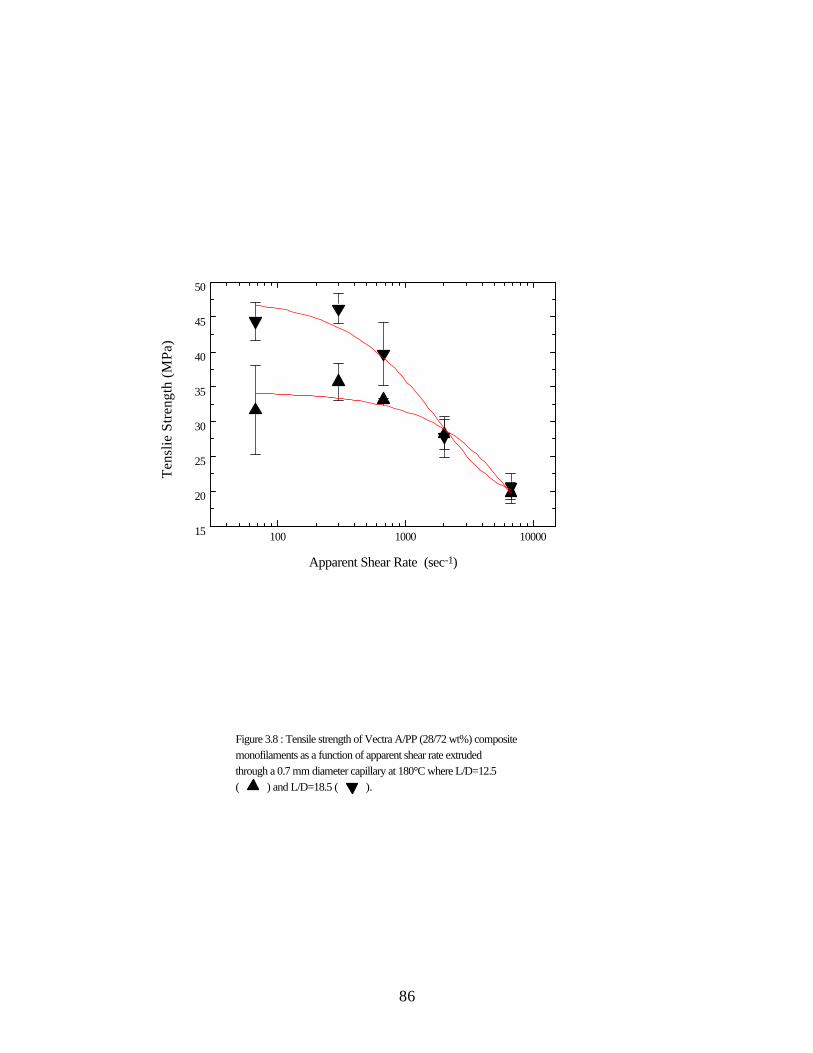
86
100 1000 1000015
20
25
30
35
40
45
50
Figure 3.8 : Tensile strength of Vectra A/PP (28/72 wt%) composite monofilaments as a function of apparent shear rate extruded through a 0.7 mm diameter capillary at 180°C where L/D=12.5 ( ) and L/D=18.5 ( ).
Tens
lie S
tren
gth
(MPa
)
Apparent Shear Rate (sec-1)

87
The effect of apparent shear rate was also examined on the tensile modulus and the tensilestrength of the Vectra A/PP (28/72 wt%) composites extruded through dies 1 and 2. In Figure3.9, the effect of apparent shear rate on the tensile moduli of the monofilaments is shown. In bothcases the moduli were somewhat constant at the lower apparent shear rates, less than 100 sec -1,and at the higher shear rates, greater than 100 sec -1, the moduli decreased. When extruded at thehighest apparent shear rate, the moduli of the monofilaments extruded through the dies weresimilar. In Figure 3.10, the dependence of the tensile strength of the monofilament on theapparent shear rate is shown. Similar to the moduli of the monofilaments, the strengths weresomewhat constant at low apparent shear rates for both dies, less than 100 sec -1, and whenextruded at higher apparent shear rates, greater than 100 sec -1, the strengths of the monofilamentsdecreased. When processed using the highest apparent shear rate, the moduli and the strengths ofthe monofilaments extruded through both dies were similar. Thus, the advantage of extrudingthrough higher L/D dies was not observed at higher shear rates.

88
10 100 10001.0
1.5
2.0
2.5
3.0
3.5
Figure 3.9 : Tensile modulus of Vectra A/PP (28/72 wt%) composite monofilaments as a function of apparent shear rate extruded through a 1.8 mm diameter capillary at 180°C where L/D=7.8 ( ) and L/D=14.2 ( ).
Tens
lie M
odul
us (G
Pa)
Apparent Shear Rate (sec-1)

89
10 100 100020
25
30
35
40
45
Figure 3.10 : Tensile strength of Vectra A/PP (28/72 wt%) composite monofilaments as a function of apparent shear rate extruded through a 1.8 mm diameter capillary at 180°C where L/D=12.5 ( ) and L/D=18.5 ( ).
Tens
ile S
treng
th (M
Pa)
Apparent Shear Rate (sec-1)

90
In Figure 3.11, a micrograph of the cross section of a monofilament is shown where themonofilament was extruded through die 4 with a constant temperature of 180°C and at thehighest apparent shear rate. The sides of the fibrils were visible in the micrograph indicating thatthe fibrils were not aligned in the direction parallel to the monofilament, nor were they necessarilyaligned in the same direction as the adjacent fibrils. Contours in the matrix formed from fibrilpullout appear as troughs in the micrograph indicating that the fibrils were embedded in the matrixat angles almost perpendicular to the direction of the monofilament. Many of the fibrils werecurved and a few were also twisted, resulting in lower effective aspect ratio and reinforcingpotential. The reduction in properties is believed to be due to a decrease in the alignment of thereinforcing fibrils, as a result of increased shear rates in the capillary.

91
Figure 3.11 : Scanning electron micrograph of the cross section of Vectra A/PP (28/72 wt%)composite monofilaments extruded through the capillary rheometer at 180°C. The monofilamentwas extruded through a capillary die with a diameter of 0.7 mm and L/D of 18.5 at an extrusionrate of 230 mg/sec.

92
The effects of temperature at which the composite strands were re-extruded through thecapillary rheometer on tensile properties of the monofilaments was examined. The Vectra A/PP(28/72 wt%) strands were extruded through die 4 at an apparent shear rate of 2.3 mg/sec and at atemperature of 180°C, 210°C, and 240°C. In Figure 3.12, the tensile modulus and strength areshown as a function of processing temperature. Clear trends were not evident because the tensileproperties were not statistically different at different processing temperatures. T he maximummodulus, 4.0 GPa, was observed when processed at 240°C while the maximum strength of 44MPa was observed at 180ºC. A micrograph of the cross section of a monofilament processed at210°C did not reveal any obvious differences in the contour of the reinforcing fibrils or in thealignment of the fibrils as compared to the monofilament extruded at 180° C (Figure 3.5a). Thereason the tensile properties appear to be independent of temperature is not clear.

93
180 190 200 210 220 230 2403.0
3.2
3.4
3.6
3.8
4.0
4.2
Figure 3.12 : Tensile modulus ( ) and strength ( ) of Vectra A/PP (28/72 wt%) composites monofilaments as a function post-processing temperature extruded through a 0.7 mm capillary with an L/D of 18.5 and an apparent shear rate of 67 sec-1.
Temperature (°C)
Tens
ile M
odul
us (G
Pa)
30
35
40
45
50
Tensile Strength (MPa)

94
The tensile properties of the monofilaments produced via post-processing of thecomposite strands in a capillary rheometer were lower than those of the strands from the dualextrusion process. The Vectra A/PP (28/72 wt%) composite strands from the dual extrusionprocess had a tensile modulus of 14.0 GPa. The effects of thermal history in a quiescentenvironment were assumed to reduce the modulus by approximately 20%. After an imposedthermal history during consolidation of the composite strands into cartridges, the modulus of thecomposites was calculated to be approximately 11 GPa. The maximum modulus of the compositeafter extrusion through the capillary rheometer system was 4.0 GPa, resulting in a significantdecrease in modulus. The low tensile properties were probably due to several reasons.Micrographs indicated that the fibrils were not fully aligned parallel to the direction of themonofilament. Micrographs also showed that the fibrils were curved and twisted which caused adecrease in the effective aspect ratio and thus decreased the reinforcing potential of the fibrils.
The tensile properties of the long fiber reinforced composites were compared to the tensileproperties of previously fabricated short fiber reinforced Vectra A prototypes. In our previouswork it was shown that the maximum tensile modulus and strength of the short fiber Vectra A/PP(40/60 wt%) composites, fabricated uniaxially in the machine direction via FDM, were 2.7 GPaand 37 MPa, respectively [12, 21]. The maximum tensile properties of Vectra A/PP (28/72 wt%)long fiber monofilaments were 4.0 GPa and 46 MPa, respectively. Therefore, the tensileproperties of the long fiber composite monofilaments were greater than those of the TLCP shortfiber reinforced composite prototypes fabricated via FDM, while the long fiber composites hadlower Vectra A concentrations. Thus, a plunger actuated FDM system would enable thefabrication of long fiber reinforced prototypes with excellent tensile properties, and the tensileproperties of these composites are far greater than those of most commercially available materialsused in FDM applications.
3.4 Conclusions
TLCP long fiber reinforced composite monofilaments were generated via a plunger drivenextrusion system. This extrusion system has the potential to be implemented in a FDM rapidprototyping system which can fabricate long fiber reinforced prototypes with tensile propertiessimilar to those of long fiber reinforced monofilaments. The tensile properties of themonofilaments generated using this extrusion system, and potentially those of prototypesfabricated from a similar FDM system, have greater mechanical properties than those of previousfabricated prototypes reinforced with short TLCP fibers.
It was found that the tensile properties of the composite monofilaments were less thanthose of the composite strands, and this was attributed to the thermal and deformation historyimposed during post-processing. It was found that the thermal history imposed duringconsolidation of 20 wt% and 40 wt% Vectra A composite strands at 180°C resulted inapproximately a 20% reduction in the tensile moduli of both materials. This reduction in tensile

95
moduli was potentially due to a decrease in orientation of the Vectra A reinforcement as a resultof molecular relaxation or as a result of poor strand alignment during consolidation.
It was determined that the deformation history during re-extrusion of the compositestrands affected the mechanical properties of the long fiber reinforced monofilaments. It wasshown that the capillary L/D, the capillary diameter, and the apparent shear rate in the capillaryaffected the properties of the composite monofilament when processed at 180°C. It wasdetermined, for the post-processing conditions considered, that smaller diameter capillary dies andlower apparent shear rates resulted in greater tensile properties of the composite monofilament. Itwas also determined, for the post-processing conditions studied, that a critical L/D was necessaryin order to obtain the optimal mechanical properties in the monofilaments.
3.5 Acknowledgments
This research was supported by the Army Research Office (Grant No. DAAH04-94-G-0282), and the Naval Surface Warfare Center, Dahlgren Division and Armstrong Laboratory,Brooks AFB under contract N60921-89-D-A239, Order 0059. Also, we would like to thank G.L. Wilkes, M. A. McLeod and B. D. Kaushiva.
1 R. W. Gray IV, D. G. Baird, J. H. Bøhn, Rap. Proto. J., in preparation (1997).2 A. I. Isayev, in Liquid-Crystalline Polymer Systems Technological Advances, ed. A. I.
Isayev, T. Kyu, and S. Z. D. Cheng, American Chemical Society, Washington D. C. 1996.3 D. G. Baird, in Polymeric Materials Encyclopedia, ed. J. C. Salamone, CRC Press, Boca
Raton 1996.4 A. A. Handlos and D. G. Baird, J. Macromol. Sci.-Rev. in Macromol. Chem. and Phy.,
C35, 183 (1995).5 E. A. Sabol, A. A. Handlos, and D. G. Baird, Polym. Comp., 16, 330 (1995).6 Himont Profax Bulletin AP-002, Himont U. S. A., Inc. (1990).7 K. G. Blizard and D. G. Baird, Polym. Eng. And Sci., 27, 653 (1987).8 R. A. Weiss, W. Hun, and L. Nicolais, Polym. Eng. And Sci., 27, 673 (1987).9 D. G. Baird and A. Sukhadia, U.S. Patent 5,225,488 (1993).10 E. A. Sabol, M. S. Thesis, Virginia Polytechnic Institute and State University (1994).11 S. M. Guskey and H. H. Winter, J. Rheol., 35, 1191 (1991).12 R. W. Gray IV, M. S. Thesis, Virginia Polytechnic Institute and State University (1997).13 C. R. Robertson, M. S. Thesis, Virginia Polytechnic Institute and State University (1994).14 C. G. Robertson and D. G. Baird, Intern. Polym. Proc., in press (1996).15 R. K. Krishnaswamy and D.G. Baird, Polym. Comp., in press (1997).16 C. G. Robertson, J. P. de Souza, and D. G. Baird, Recent Advances in Liquid Crystalline
Polymers, A. I. Isayev, T. Kyu, and S. Z. D. Cheng eds., ACS Books, Washington D. C.(1996).

96
17 A. A. Handlos and D. G. Baird, Intern. Polym. Proc., XI, 82 (1996).18 A. A. Handlos and D. G. Baird, Polym. Comp., 17, 73 (1996).19 A. A. Handlos and D. G. Baird, Polym. Eng. and Sci., 36, 378 (1996).20 R. K. Krishnaswamy, J. Xue, and D. G. Baird, SAMPE J., in preparation (1997).21 R. W. Gray IV, D. G. Baird, J. H. Bøhn, in preparation (1997).22 M. Y. Cao and B. Wunderlich, J. Polym. Sci.: Polym. Phy. Ed., 23, 521 (1985).23 Amoco Polypropylene Homopolymers Bulletin PP-8n, Amoco Polymers, Inc. (1996).24 G. Crevecoeur and G. Groeninckx, Polym. Eng. and Sci., 30, 532 (1990).25 J. C. Halpin, Polym. Eng. and Sci., 16, 344 (1976).26 H. N. Yoon, L. F. Charbonneau, and G. W. Calundann, Adv. Mater., 3, 206 (1992).27 Y. G. Lin and H. H. Winter, Macromol., 21, 2439 (1988).

97
4.0 Recommendations
• Develop TLCP composites with very high TLCP loading, and use a carrier with an extremelylow viscosity for FDM applications. This has the potential of increasing the mechanical propertiesof the composite by using greater quantities of TLCP. The viscosity ratio between the two phasescould develop a sheath core morphology (e.g., a low viscosity polyphenylenesulfide PPS andVectra B). Thus, the sheath region could serve to provide adhesion between adjacent roads andlayers. These high TLCP concentration composites could be processed both above and below themelting point of the TLCP. The strength of the prototypes could be enhanced if the sheathmaterial could be cross-linked after fabrication.
• Design a die to be used in FDM rapid prototyping applications that is able to develop orientationin the reinforcing phase. The die should be designed considering the conclusions madeconcerning die geometry for long fiber reinforced systems. This has the potential to increase fibrilalignment in prototypes fabricated from composites where the reinforcement was developed in thedual extrusion process. A second die should be designed to develop strong extensional stress thatcould better orient TLCPs in the melt state, thus generating the reinforcement in situ.
• Design a FDM rapid prototyping system that is more robust than the system used in thisresearch. The new system should be able to extrude resin in pellet and powder form and be ableto generate and withstand pressures that are typically present during polymer processing. Thenew extrusion system should also be designed such that it could easily be cleaned, allowing manymaterials to be used in the system. The system should also be designed to withstand thetemperatures required for processing engineering thermoplastics. If the purpose if the rapidprototyping system is to fabricate parts from composites generated using the dual extrusionsystem, a ram extrusion system should be used. If the purpose of the system, however, is tofabricate prototypes using unfilled resins, a screw extrusion system should be implemented.
• It was shown that long fiber composites extruded through a die had better mechanical propertiesthan those of short fiber composites. It would be beneficial if long fiber monofilaments could begenerated by consolidating several strands from the dual extrusion process to form amonofilament using a continuous process. This could be accomplished by passing the strandsthrough rollers where a desired cross-section had been removed from the rollers’ surface. This

98
could be used to produce monofilaments for FDM applications, or the monofilaments could bepelletized for post-processing using conventional processing equipment.

99
Appendix A :
Rheology Data

100
0.01 0.1 1 10 100 1000100
1000
Figure A.1: | η*| ( ) as a function of frequency for ABS used in the
FDM 1600 rapid prototyping system at 270°C and at 5% strain.
| η* |
(Pa•
s)
ω (rad/s)

101
0.01 0.1 1 10 100 1000100
1000
10000
Figure A.2 : |η*| ( ) as a function of frequency for 4018
grade PP at 183 °C and at 10% strain.
|η* |
(Pa•
s)
ω (rad/s)

102
0 500 1000 1500 2000100
1000
Figure A.3 : |η*| as a function of time for Amaco 4018 grade
PP at an angular frequency of 1 rad/s and at 10% strain for three
temperature 242°C ( ), 262°C ( ), and 282°C( ).
|η* |
(Pa•
s)
Time (s)

103
Appendix B :
DMTA Data

104
0 50 100 150 2001E7
1E8
1E9
1E10
Figure B.1 : G' [heating ( ) cooling ( )] and G'' [heating ( )
cooling ( )] as a function of time where a neat Vectra A injection
molded plaque was heated at a rate of 10°C/min until it reached 200°C. It was
held at temperature for 10 minutes and then cooled at the same rate at a
frequency of 1 (rad/sec), and at 0.1% strain. The plaque was 1.1mm thick.
G' (
Pa) a
nd G
'' (Pa
)
Temperature °C
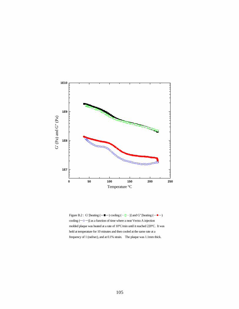
105
0 50 100 150 200 250
1E7
1E8
1E9
1E10
Figure B.2 : G' [heating ( ) cooling ( )] and G'' [heating ( )
cooling ( )] as a function of time where a neat Vectra A injection
molded plaque was heated at a rate of 10°C/min until it reached 220°C. It was
held at temperature for 10 minutes and then cooled at the same rate at a
frequency of 1 (rad/sec), and at 0.1% strain. The plaque was 1.1mm thick.
G' (
Pa) a
nd G
'' (Pa
)
Temperature °C

106
0 50 100 150 200 250
1E7
1E8
1E9
1E10
Figure B.3 : G' [heating ( ) cooling ( )] and G'' [heating ( )
cooling ( )] as a function of time where a neat Vectra A injection
molded plaque was heated at a rate of 10°C/min until it reached 200°C. It was
held at temperature for 10 minutes and then cooled at the same rate at a
frequency of 1 (rad/sec), and at 0.1% strain. The plaque was 1.1mm thick.
G' (
Pa) a
nd G
'' (Pa
)
Temperature °C

107
Appendix C :
Micrographs

108
Figure C.1 : Scanning election micrograph of the cross-section of a Vectra A/PP (40/60 wt%)strand spun via the dual extrusion system using a capillary die having a diameter of 1.8 mm andL/D=1 and taken up at draw to ratios greater than 70.

109
Figure C.2 : Scanning election micrograph of the cross-section of a Vectra A/PP (40/60 wt%)plaque consolidated from uniaxially aligned strands spun via the dual extrusion system using acapillary die having a diameter of 1.8 mm and L/D=1 and taken up at draw to ratios greater than70.

110
Appendix D :
FDM 1600 Operating Procedure

111
When using the FDM 1600 rapid prototyping system, the following protocol should beused. The protocol is divided into two sections: software and hardware. The software providesthe series of directions necessary to the hardware, so that it can perform the necessary tasks tofabricate a particular prototype.
D.1 : A .sml file must be created containing specific instructions for part fabrication. It can becreated using two different methods.
• Software packages can be employed to generated this file. First, the CAD system I-DEAS isemployed to generate a mesh of the proposed part. This is then saved as a .stl file. Thissoftware is found in the Virginia Tech Computer Aided Design Laboratory along with themanuals. The .stl file can then be loaded into QuickSlice, a software package that generatesthe .sml file. The .sml file is a series of instructions containing the tool path and theextrusion rates necessary to fabricate a particular prototype. This application and manualsare also found in the Virginia Tech CAD Laboratory.
• The .sml file can also be generated by writing a computer program that writes .sml files. TheC++ program used in this research along with a representative .sml file are shown inAppendix E.
D.2 : Before the part can be built a series of hardware procedures must be completed.• The proper head with the proper material must be installed in the FDM 1600 rapid prototyping
system. The procedures for the these two steps are described in detail in the FDM SystemDocumentation in the FDM Hardware Section entitled FDM 1600 Manual Release 2.0 onpages F16-18 through F16-28 (5OCT95).
• The liquefier head must then be positioned before each part is fabricated. This is described onpages F16-32 and F16-33 (5OCT95) of the afore-mentioned section. It is also described inthe Training Section of the manual entitled QuickSlice Training Manual Release 4.0 pagesT-12 and T-13 (12AUG96).
• To fabricate a part, the .sml is then sent to the FDM 1600 rapid prototyping system from theSilicon Graphics workstation, following the procedure in the Training Section of the manualentitled QuickSlice Training Manual Release 4.0 pages T-11 (12AUG96). The UNIXcommand "ssend" is also described in the Utilities Section entitled Utilities Manual Release4.0 pages U-9 and U-10 (20DEC96).
• The tips of the two liquefier dies on the head must be calibrated with respect their relativeposition to each other. The procedure for this is found on pages F16-13 through F16-18(5OCT95) of the FDM Hardware Section. This needs to by performed every time the diesare adjusted.
• If a new material is being used, the extrusion rate of the material needs to be calibrated. Thisis explained in Appendix D.3.
• Before removing the head, the liquefier needs to be purged. This process is described in detailin Appendix D.4.
D.3 : The line speed of the monofilament feed stock needs to be calibrated for every material andfor the same material having a different diameter feed stock. The .sml file specifies the

112
monofilament line speed. Thus a change in feed stock diameter changes the volumetric flow rate.The line speed is specified in the command
PD.08,41;MM;MM0,53;MM006,100;MM-70,175;SR800;AC5;
The line is described in detail in the Utilities Section of the manual entitled Utilities Manual onpages U-2 and U-3 (20DEC96). The C++ code in Appendix E defines this line as "const charparameter_string []". The line can easily be changed by: changing the string in the C++ program,compiling the code, and generating a new .sml file. To calibrate the command line for a newmaterial where the C++ code is used to generate the .sml file:
• Determine the desired cross-sectional area of the road in mil2(1 mil = 0.001 inches = 0.025mm).
• Find this number in the DEF file in Appendix E under the column titled "Flow Area."• Find the corresponding DO number (digital output number).• In the C++ code insert the DO number into the "const char parameter_string []" as indicated.
PD.08,41;MM;MM0,53;MM006,100;MM-70,175;SR800;AC5;
• Save the C++ code, and compile the file by typing "make". (The make file is shown inAppendix E).
• Build a simple part such as a rectangular prism.• Measure the part dimensions and determine if too much or not enough material was used.• Adjust the "const char parameter_string []" as necessary and repeat until the dimensions of the
final part are similar to that expected.
D. 4 : If the liquefier is not dedicated to a specific material, it is import to purge the liquefier aftereach use.
• A suitable purge material must be chosen. The purge material and the modeling should havesimilar processing temperatures, and neither should degrade at the processing temperatureof the other. In this research ABS was used as the purge material.
• Unload the modeling material from the head.• Adjust the liquefier temperature to the processing temperature of the purge material.• Load the purge material.• Purge the using the "Load" button in the front of the FDM 1600 system, until all of the model
material has been removed. {If some material cannot be removed using this method removethe liquefier from the head by removing the screws that secure the liquefier in the head.Then remove the insulation and heater from the liqufier. Place it in a furnace to carbonizethe material. The carbon can be removed from the liquefier by placing in an ultrasonic bath.(Avoid removing the liquefier if possible!)}
• Remove the head using the procedure previously referenced.

113
Appendix E :
C++ Code

114
The FDM 1600 rapid prototyping system requires a series of directions that position theliquefier head and dictate the extrusion rate of both the support and model material. Becausesome of the materials used in this research could not easily separate from the die upon thecompletion of a road, it was necessary that the part be built from exactly one continuos road.However, the existing software, QuickSlice, was unable to develop a tool path for a partconsisting of a single continuos road. Therefore, the following C++ code was developed togenerate .sml files that were used to build rectangular prisms with a continuous road via the FDM1600 rapid prototyping system operating with QuickSlice 2.0.
This program can easily be altered to generate parts of varying dimensions, lay-downpatterns, and materials. The dimensions of the part are specified by the global variables and caneasily be changed. The lay-down pattern used during part fabrication can also be dictated. This isdone by placing remark commands in front of all of the subroutines whose name starts with "plaq"in the main routine except the subroutine of the lay-down pattern to be used. Varying materialscan also be used. The processing temperature of the material must be specified manually usingthe controllers on the front of the FDM 1600 rapid prototyping system. The mass rate of thematerial is adjusted by changing the linear speed of the monofilament feed stock. This is specifiedby the "const char parameter_string []", and is discussed in Appendix D.3.
The C++ program accesses an existing .sml file named "t12_2plaq.sml" in order to buildthe base. The base fabricated by this .sml file is a constant size and thus does not change with theprototype size.
The "const char parameter_string []" was calibrated by Stratasys, Inc. for ABS plastic.The QuickSlice software accesses this calibration table, "DEF", while generating the .sml file.This table is used as a first approximation when calibrating the monofilament line speed for newmaterials

115
Summary of Files Listed in Appendix E
C++ code : Creates .sml files............................................................................................ 116DEF : Contains calibrations to build ABS parts with differing road size............................ 122MAKEFILE : Compiles and links all programs................................................................. 126t12_2plaq.sml : File containing directions for building the base......................................... 127.sml file : sample file generated by the C++ code............................................................... 141

116
C++ code : Creates .sml files// Robert Gray// tensile bar sample generator// Jan. 1997//_____________________________
#include <math.h>#include <fstream.h>#include <iostream.h>#include <stdio.h>#include <stdlib.h>
const float height = 80; // part height in mil(height/roadhei=int);const float width = 300; // part width in mil(width/roadwi/2=int);const float length = 3000; // part length in mil(length/roadwi/2=int);const float road_height = 10; // road height in mil;const float road_width = 30; // road width in mil;const int start_XX = 150; // start postion of the part in the X direction in mils;const int start_YY = 100; // start postion of the part in the Y direction in mils;const int num_of_plaques = 8; // number of plaques to be builtconst int lay_pattern = 3; // lay down pattern // 1 = machine direction // 2 = transverse direction // 3 = zero nintyconst char parameter_string[]= "PD.151,47;MM;MM0,33;MM50,178;MM-83,161;SR800;AC5;WA0.;#ORD:34Z:0.0400 S:0.0400\n";//material parametersconst char my_file[] = "com100a.sml"; // file to write sml code to Va/4018 20/80 chopped monoconst char my_support[] = "t12_2plaq.sml"; // file to read support from_ two layers of fineofstream OFile;
void Initialisation();void OrigineSetup();void MaterialInit();void InsertSupportCode();void plaq_machine_direction(int, int);void plaq_machine_layer(int, int);void plaq_transverse_direction(int, int);void plaq_transverse_layer(int, int);void plaq_zero_ninty(int, int);void plaq_several(int, int);void SetEndWork();
int main(){ OFile.open(my_file);
Initialisation(); OrigineSetup();
MaterialInit();OFile.close();InsertSupportCode(); // try to use system command to add support.structure my_supportOFile.open(my_file, ios::out|ios::app);
// plaq_machine_direction(start_XX, start_YY);// plaq_transverse_direction(start_XX, start_YY); plaq_zero_ninty(start_XX, start_YY);// plaq_several(start_XX, start_YY);
SetEndWork();OFile.close();return 0;
}
//////void

117
Initialisation() {OFile << "�.K;;;;;�.J;;;;;�.R\n";OFile << "�.I;;17:\n";OFile << "�.N10;19:\n";OFile << "�.M10;;;;;:\n";OFile << "�.E;;;;;;;\n";OFile << "# Date : 09/28/96 23:32:29\n";OFile << "# File : /usr2/research/chem/rogray/plaq/plaq3.sml\n";OFile << "# QuickSlice : 2.0a 03-Apr-96 (qsqk) ----------------- units = inc h\n";OFile << "# Modeler : FDM1600\n";OFile << "# Material : ABS_P400 and PP VA microcomposites\n";OFile << "IN;\n";OFile << "CD129;WA1;CD0; # alt-tip off, enable operator alt mat change\n";OFile << "# CF;\n";OFile << "# VC100;OF;\n";OFile << "# V*100,1.;#Xshrinkage\n";OFile << "# V*101,1.;#Yshrinkage\n";OFile << "# CF@100,@101;\n";OFile << "# CZ100;\n";OFile << "MZ1200;\n";OFile << "FH;XD210;FZ;\n";OFile << "MZ1200;\n";OFile << "MA1200,500; # take this out if res tarting a model\n";OFile << "# MA@102,@103; # put this in if restarting a model\n";OFile << "XD121;#TW\n";OFile << "#\n";OFile << "# The toolpath units are in inches.\n";OFile << "# ORD HEADER # normal\n";OFile << "# ORD list is all possible curve types, whether used or not.\n";OFile << "# Wait (once per Z, next Z)\n";OFile << "# Pre Main Shut Roll | \n";OFile << "# Delay Start-flow Flow off back Speed | Setname, Type\n";OFile << "# | | | | | | | | \n";OFile << "#ORD: 1 PD.118,79;MM;MM0,25;MM60,122;MM-70,175;SR800;AC5;WA0.;#DEFAULT,Open\n";OFile << "# height = " << height << " all values are in mils\n";OFile << "# width = " << width << " \n";OFile << "# length = " << length << " \n";OFile << "# road_height = " << road_height << " \n";OFile << "# road_width = " << road_width << " \n";OFile << "# start_XX = " << start_XX << " \n";OFile << "# start_YY = " << start_YY << " \n";OFile << "# num_of_plaques = " << num_of_plaques << " \n";OFile << "# lay_pattern = " << lay_pattern << " \n";OFile << "# parameter_string = " << parameter_string << " \n";OFile << "# my_file = " << my_file << " \n";OFile << "# my_support = " << my_support << " \n";OFile << "# road width max 60 mil min 30 mil for 25 mil tip:height 10 mil\n";
OFile << "# road width max 30 mil min 12 mil for 12 mil tip:height 10 mil\n";}
////////
voidOrigineSetup() {
OFile << "MZ0; # FOAM HEIGHT FACTOR HERE \n";OFile << "PS;WA0;VC102;OA;SO@102,@103;VC104;OZ;MR0,0;\n";OFile << "VS110,@102;VS111,@103;VS112,@104;\n";OFile << "V+110,@121;V+111,@122;\n";OFile << "AM0;\n";
}
////////
void

118
MaterialInit() {OFile << "########## MATERIAL INITIALIZATION\n";OFile << "CD129;WA1; # alt-tip off\n";OFile << "CD135; # RB RNG ABS\n";}
////////
voidInsertSupportCode() { char line[100]; sprintf(line,"cat %s >> %s",my_support,my_file);
system(line);
}
////////
voidSetEndWork() {
OFile << "# TAIL #\n";OFile << "VM7;\n";OFile << "MZ20;\n";OFile << "CD129;WA1;CD0; # alt-tip off\n";OFile << "#\n";OFile << "# dz=0.010 co=0.0060 dp=0.0010 ct=0.0006 alt=0 ff=0.1200 u=inch\n";OFile << "#\n";OFile << "XD211;\n";OFile << "####........................................................................\n";OFile << "# Date : 01/02/97\n";OFile << "# File : /usr2/research/chem/rogray/plaq/\n";OFile << "# Qui ckSlice : 2.0a 03-Apr-96 (qsqk)\n";OFile << "# Modeler : FDM1600\n";OFile << "# Material : ABS_P400 and vectra A / PP blends\n";OFile << "# Shrinkage XY : 1.008\n";OFile << "# Z : 1\n";OFile << "# Applied : yes\n";OFile << "# Road width min : inch\n";OFile << "# max : \n";OFile << "# Tip : 0.025\n";OFile << "# Envelope X : 9.4 inch\n";OFile << "# Y : 10\n";OFile << "# Z : 10\n";OFile << "# Wip e interval : no wipe\n";OFile << "#...........................................................................\n";OFile << "# Estimated values......\n";OFile << "# Modeling time : hours (approx)\n";OFile << "# Filament usage : \n";OFile << "# main : \n";OFile << "# support : \n";OFile << "####........................................................................\n";
}
/////////////////////////////////////////////////////////////////////The part building procedures //// /////////////////////////////////////////////////////////////////////
////////////////////machine////////////////////

119
voidplaq_machine_direction(int X,int Y) {// X and Y are the absolute points of the corner were thepart will start to build from
int JJ;
OFile << "#######\n\n"; OFile << "## build material \n\n"; OFile << "#######\n\n";
OFile << "\n XD129; #alt-tip off\n";OFile << "MA" << (.5*road_width+X) << "," << (.5*road_width+Y) << ";#start
position \n"; for ( JJ=1; JJ<=(height/road_height/2); JJ++)
{plaq_machine_layer(X, Y);}
}
voidplaq_machine_layer(int XX,int YY) {//XX and YY are the absolute value of the cornerwere the layeris started from
int II,l;
OFile << "MZ" << (road_height*2) << "; #next layer\n"; OFile << parameter_string; OFile << "AS1;VM4;BC;#st art flow begin series of movements\n";
for ( II=1; II<=(width/road_width/2); II++) { for ( l=1 ;l<=5;l++)
{if (II==(48*l)) {OFile << "EC;VM3;WA2; #curve length break up\n";
OFile << parameter_string; OFile << "AS1; VM4; BC; #re start\n";
OFile << "MA" << (.5*road_width+XX) << "," <<(.5*road_width)+(road_width*(2*II-3))+YY << ";\n";
} }
OFile << "MA" << (.5*road_width+XX) << "," <<(.5*road_width)+(road_width*(2*II-2))+YY << ";\n";
OFile << "MA" << (length-(.5*road_width)+XX) << "," <<(.5*road_width)+(road_width*(2*II-2))+YY << ";\n";
OFile << "MA" << (length-(.5*road_width)+XX) << "," <<(.5*road_width)+(road_width*(2*II-1))+YY << ";\n";
OFile << "MA" << (.5*road_width+XX) << "," <<(.5*road_width)+(road_width*(2*II-1))+YY << ";\n";
} OFile << "EC; VM3;#end series of movements end flow\n"; OFile << "XD209; # capture postion FC\n"; OFile << "MZ" << (road_height*2) << ";#next layer\n"; OFile << parameter_string; OFile << "AS1;VM4;BC;# start flow begin series of movements\n";
for ( II=(width/road_width/2); II>=1 ; II--) { for ( l=1 ;l<=5;l++)
{if (II==(48*l)) {OFile << "EC;VM3;WA2; #curve length break up\n";
OFile << parameter_string; OFile << "AS1; VM4; BC; #re start\n";
OFile << "MA" << (.5*road_wid th+XX) << "," <<(.5*road_width)+(road_width*(2*II))+YY << ";\n";
} } OFile << "MA" << (.5*road_width+XX) << "," <<
(.5*road_width)+(road_width*(2*II-1))+YY << ";\n"; OFile << "MA" << (length-(.5*road_width)+XX) << "," <<
(.5*road_width)+(road_width*(2*II-1))+YY << ";\n";

120
OFile << "MA" << (length-(.5*road_width)+XX) << "," <<(.5*road_width)+(road_width*(2*II-2))+YY << ";\n";
OFile << "MA" << (.5*road_width+XX) << "," <<(.5*road_width)+(road_width*(2*II-2))+YY << ";\n";
}
OFile << "EC; VM3;#end flow end series of movements \n"; OFile << "XD209; #capture postion FC\n";
}
///////////////////////transverse///////////////////////
voidplaq_transverse_direction(int X, int Y) {// X and Y are the absolute points of the corner werethe part will be started from int JJ ;
OFile << "#######\n\n"; OFile << "## build material \n\n"; OFile << "#######\n\n";
OFile << "XD129; #alt-tip off\n";OFile << "MA" << ((.5*road_width)+X) << "," << ((.5*road_width)+Y) << ";#start
postion\n"; for ( JJ=1; JJ<=(height/road_height/2); JJ++)
{plaq_transverse_layer(X, Y);}
}
voidplaq_transverse_layer(int XX, int YY) {// XX and YY are the absolute points of the corner werethe layer will start and end at
int II,l;
OFile << "MZ" << (road_height*2) << ";#next layer\n"; OFile << parameter_string; OFile << "AS1;VM4;BC;#begin flow begin series of movements\n";
for ( II=1; II<=(length/road_width/2); II++) { for ( l=1 ;l<=5;l++)
{if (II==(48*l)) {OFile << "EC;VM3;WA2; #curve length break up\n";
OFile << parameter_string; OFile << "AS1; VM4; BC; #re start\n";
OFile << "MA" << (.5*road_width)+(road_width*(2*II-3))+XX <<"," << (.5*road_width+YY) << ";\n";
} } OFile << "MA" << (.5*road_width)+(road _width*(2*II-2))+XX << "," <<
(.5*road_width+YY) << ";\n"; OFile << "MA" << (.5*road_width)+(road_width*(2*II-2))+XX << "," <<
(width-(.5*road_width))+YY << ";\n"; OFile << "MA" << (.5*road_width)+(road_width*(2*II-1))+XX << "," <<
(width-(.5*road_width))+YY <<";\n";
OFile << "MA" << (.5*road_width)+(road_width*(2*II-1))+XX << "," <<(.5*road_width+YY) << ";\n";
} OFile << "EC; VM3;#end series of movements\n"; OFile << "XD209; # capture position FC\n"; OFile << "MZ" << (road_height*2) << ";#next layer\n";

121
OFile << parameter_string; OFile << "AS1;VM4;BC;# begin flow begin series of movements\n";
for ( II=(length/road_width/2); II>=1 ; II--) { for ( l=1 ;l<=5;l++)
{if (II==(48*l)) {OFile << "EC;VM3;WA2; #curve length break up\n";
OFile << parameter_string; OFile << "AS1; VM4; BC; #re start\n";
OFile << "MA" << (.5*roa d_width)+(road_width*(2*II))+XX <<"," << (.5*road_width)+YY << ";\n";
} }
OFile << "MA" << (.5*road_width)+(road_width*(2*II-1))+XX << "," <<(.5*road_width)+YY << ";\n";
OFile << "MA" << (.5*road_width)+(road_width*(2*II-1))+XX << "," <<(width-(.5*road_width))+YY << ";\n";
OFile << "MA" << (.5*road_width)+(road_width*(2*II-2))+XX << "," <<(width-(.5*road_width))+YY << ";\n";
OFile << "MA" << (.5*road_width)+(road_width*(2*II-2))+XX << "," <<(.5*road_width)+YY << ";\n";
}
OFile << "EC; VM3;# end flow end series of movements\n"; OFile << "XD209; # capture postionFC\n";
}
///////////////////// Zero Ninty/////////////////////
voidplaq_zero_ninty(int X, int Y) {// X and Y are the absolute points of the corner of the part
int JJ;
OFile << "XD129; #alt-tip off\n";OFile << "MA" << (X) << "," << (Y) << ";#start postion\n";
for ( JJ=1; JJ<=(height/road_height/4); JJ++) {plaq_transverse_layer(X, Y); plaq_machine_layer(X, Y);} }
/////////////////////////////// several plaques are made// of a particular lay down// pattern////////////////////////////
voidplaq_several(int XX, int YY) {// XX and YY are the absolute corner of the first part
int KK,xx,yy; xx = XX; yy = YY;
for ( KK=1; KK<= (num_of_plaques); KK++){ if (lay_pattern == 1) plaq_machine_direction(xx, yy); if (lay_pattern == 2) plaq_transverse_direction( xx, yy); if (lay_pattern == 3) plaq_zero_ninty(xx, yy); yy=yy+width+200;}
}

122
DEF : Contains calibrations to build ABS parts with differing road size# $Id: DEF,v 1.18 1997/01/07 20:10:08 phopkins Exp $# File: strata/modelers/1600/P400/T25/Z10/DEF#--------------------------------------------------------------------------#
#--------------------------------------------------------------------------## WARNING: Preset values defined by Stratasys Inc.# Any changes made to this file are at your own risk.# Stratasys Inc. will not support any non-Stratasys changes to this file.#--------------------------------------------------------------------------#
IDENT $Revision: 1.18 $
FILEUNITS INCH # units for commands in current file only { INCH | MM }
MODELER 1600 {9.4 10.0 10.0} {.1 .1 .0} {1.2 .5 .0} 0.026
MATERIAL P400 {1.007 1.0} 52
TIP T25 {.010 .020} {.025 .08} {1.5 4.0}
ACCELERATION 5DEFL_ANGLE 30 70 110ZIGZAG 0.06 6TIP_WIPE 2 "XD121;#TW"ROLLBACK_M "CD135;#ABS RB_SF"DENSITY 1.05SHORT 0.20BASE_BOTTOM_Z .015 .030
P1 20PO 0.25
# PURGE ---------------------------------------------------------------------### idle time between tip use (table gives purge time in seconds)## 0 1 10 20 30 40 50 60 + (minutes)PV 1 0 1 1 1 5 5 5 5 # very dry material 0 - 0.249PV 2 1 1 1 2 5 5 5 5 # medium dry 0.25 - 0.499PV 3 1 1 2 2 5 5 5 5 # medium 0.50 - 0.749PV 4 1 1 2 2 5 5 5 7 # medium wet 0.75 - 0.999PV 5 2 2 2 2 5 5 5 10 # very wet material 1.0 - greater# PURGE END -----------------------------------------------------------------#
# SETS START --------------------------------------------------------------#G 0 DEFAULT DACBa0 NO In-Out MOD 45 -45 .000 .000 .050 RED 0 0.0 \.028 OFF .999 99 99 99 999 -99 999 999 99 FORW .10 SOLID \.028 IN .999 99 99 99 999 -99 999 999 99 START .10 SOLID \.028 .000 .999 99 99 99 999 -99 999 999 99 FORW .10 SOLID YES \.028 .000 .999 99 99 99 999 -99 999 999 99 START .10 SOLID
G 1 Part DACBa0 NO In-Out MOD 45 -45 .000 .000 .050 RED 0 0.0 \.028 OFF .999 99 99 99 999 -99 999 999 99 FORW .10 SOLID \.028 IN .999 99 99 99 999 -99 999 999 99 START .10 SOLID \.028 .000 .999 99 99 99 999 -99 999 999 99 FORW .10 SOLID YES \.028 .000 .999 99 99 99 999 -99 999 999 99 START .10 SOLID
G 3 PartFast DCABa1 NO In-Out MOD 45 -45 .000 -.002 .050 LIGHT-RED 2 0.0 \.028 OFF .999 99 99 99 999 -99 999 999 99 FORW .10 SOLID \.028 IN .999 99 99 99 999 -99 999 999 99 START .10 SOLID \.056 .000 .999 99 99 99 999 -99 999 999 99 FORW .10 SOLID YES \.028 .000 .999 99 99 99 999 -99 999 999 99 START .10 SOLID
G 5 SupportFace DACBa0 NO In-Out ALT -22 -22 .005 .000 .050 LIGHT-GREEN 0 0.0 \.028 OFF .999 99 99 99 999 -99 999 999 99 FORW .10 SOLID \.028 OFF .999 99 99 99 999 -99 999 999 99 START .10 SOLID \.028 .000 .999 99 99 99 999 -99 999 999 99 FORW .10 SOLID YESA \.028 .000 .999 99 99 99 999 -99 999 999 99 START .10 SOLID

123
G 6 Support DACBa0 NO In-Out ALT 68 68 .005 .000 .050 LIGHT-YELLOW 0 0.0 \.028 OFF .999 99 99 99 999 -99 999 999 99 FORW .10 SOLID \.028 OFF .999 99 99 99 999 -99 999 999 99 START .10 SOLID \.028 .035 .999 99 99 99 999 -99 999 999 99 FORW .10 SOLID YESA \.028 .000 .999 99 99 99 999 -99 999 999 99 START .10 SOLID
G 7 SupportFast DACBa1 NO In-Out ALT -22 -22 .005 .000 .050 DARK-GRAY 1 0.0 \.028 OFF .999 99 99 99 999 -99 999 999 99 FORW .10 SOLID \.028 OFF .999 99 99 99 999 -99 999 999 99 START .10 SOLID \.028 .250 .999 99 99 99 999 -99 999 999 99 FORW .10 SOLID YESA \.028 .000 .999 99 99 99 999 -99 999 999 99 START .10 SOLID
G 8 BaseTop DACBa0 NO In-Out ALT -32 -32 .000 .000 .050 BLUE 0 0.0 \.028 OFF .999 99 99 99 999 -99 999 999 99 FORW .10 SOLID \.028 OFF .999 99 99 99 999 -99 999 999 99 START .10 SOLID \.028 -.004 .999 99 99 99 999 -99 999 999 99 FORW .10 SOLID YESA \.028 .000 .999 99 99 99 999 -99 999 999 99 START .10 SOLID
G 9 BaseFast DACBa1 NO In-Out ALT 68 68 .000 .000 .050 LIGHT-BLUE 0 0.0 \.028 OFF .999 99 99 99 999 -99 999 999 99 FORW .10 SOLID \.028 OFF .999 99 99 99 999 -99 999 999 99 START .10 SOLID \.028 .050 .999 99 99 99 999 -99 999 999 99 FORW .10 SOLID YESA \.028 .000 .999 99 99 99 999 -99 999 999 99 START .10 SOLID# SET END -----------------------------------------------------------------#
# PDMM START --------------------------------------------------------------#
#------ CURVES ------------------------------------------------------------## Flow D Pre Pre Start Start Shut Roll# Area O Delay Flow Flow Dis. Off Back Speed# xxxx xxx .xxx xxx xxx xxx xxx xxx xxxxx
PDMM 30 2 .065 47 13 50 15 139 800 31 4 .066 47 13 50 16 139 800 32 6 .067 47 13 50 17 139 800 33 8 .068 47 13 50 18 139 800 34 10 .069 47 15 50 19 139 800 35 12 .070 47 15 50 20 139 800 36 14 .071 47 15 50 21 139 800 37 16 .072 47 15 50 22 139 800 38 18 .073 47 17 50 23 139 800 40 20 .074 47 17 50 24 139 800 41 22 .075 47 17 50 25 139 800 42 24 .076 47 17 50 26 139 800 44 26 .077 47 17 50 27 141 800 45 28 .078 47 17 50 28 141 800 46 30 .079 47 17 50 29 141 800 48 32 .080 47 19 50 30 141 800 49 34 .081 47 19 50 31 141 800 51 36 .082 47 19 50 32 141 800 53 38 .083 47 19 50 33 143 800 54 40 .084 47 19 50 34 143 800 56 42 .085 47 19 50 35 143 800 58 44 .086 47 19 50 36 143 800 60 46 .087 47 19 50 37 143 800 62 48 .088 47 21 50 38 143 800 64 50 .089 47 21 50 39 145 800 66 52 .090 47 21 50 40 145 800 68 54 .091 47 21 50 41 145 800 70 56 .092 47 21 50 42 145 800 72 58 .093 47 21 50 43 145 800 74 60 .094 47 21 50 44 145 800 77 62 .095 47 21 50 45 147 800 79 64 .096 47 21 50 46 147 800 82 66 .097 47 23 50 47 147 800 85 68 .098 47 23 50 48 147 800 87 70 .099 47 23 50 49 147 800 90 72 .100 47 23 50 50 147 800 93 74 .101 47 23 50 51 149 800

124
96 76 .102 47 25 50 52 149 800 99 78 .103 47 25 50 53 149 800 102 80 .104 47 25 50 54 149 800 106 82 .105 47 25 50 55 149 800 109 84 .106 47 25 50 56 149 800 113 86 .107 47 25 50 57 149 800 116 88 .108 47 25 50 58 151 800 120 90 .109 47 25 50 59 151 800 124 92 .110 47 25 50 60 151 800 128 94 .111 47 27 50 61 151 800 132 96 .112 47 27 50 62 151 800 136 98 .113 47 27 50 63 151 800 141 100 .114 47 27 50 64 151 800 146 102 .115 47 27 50 65 151 800 150 104 .116 47 27 50 66 153 800 155 106 .117 47 29 50 67 153 800 160 108 .118 47 29 50 68 153 800 166 110 .119 47 29 50 69 153 800 171 112 .120 47 29 50 70 153 800 177 114 .121 47 29 50 71 153 800 182 116 .122 47 29 50 72 153 800 188 118 .123 47 29 50 73 155 800 195 120 .124 47 29 50 74 155 800 201 122 .125 47 29 50 75 155 800 208 124 .126 47 29 50 75 155 800 214 126 .127 47 29 50 75 155 800 221 128 .128 47 31 50 75 155 800 229 130 .129 47 31 50 75 157 800 236 132 .130 47 31 50 75 157 800 244 134 .131 47 31 50 75 157 800 252 136 .131 47 33 50 75 159 800 260 138 .133 47 33 50 75 159 800 269 140 .136 47 33 50 77 159 800 277 142 .139 47 33 50 79 159 800 287 144 .143 47 33 50 81 161 800 296 146 .147 47 33 50 81 161 800 306 148 .151 47 33 50 83 161 800 316 150 .156 47 35 50 83 161 800 326 152 .162 47 35 50 83 163 800 337 154 .166 47 35 50 83 163 800 348 156 .172 47 37 50 83 163 800 359 158 .178 47 37 50 83 163 800 371 160 .182 47 37 50 83 165 800 383 162 .186 47 39 50 83 165 800 396 164 .190 47 39 50 83 165 800 409 166 .199 47 41 50 83 167 800 422 168 .208 47 41 50 83 167 800 436 170 .214 47 41 50 83 167 800 450 172 .220 47 43 50 83 169 800 465 174 .227 47 43 50 83 169 800 481 176 .233 47 45 50 83 169 800 496 178 .239 47 45 50 83 171 800 513 180 .246 47 45 50 83 171 800 530 182 .253 47 47 50 83 171 800 547 184 .260 47 47 50 83 173 800 565 186 .265 47 47 50 83 173 800 584 188 .270 47 49 50 83 173 800 603 190 .275 47 49 50 83 173 800 623 192 .280 47 49 50 83 175 800 643 194 .285 47 51 50 83 175 800 664 196 .290 47 51 50 83 175 800 686 198 .294 47 51 50 83 175 800 709 200 .298 47 51 50 83 177 800 732 202 .302 47 53 50 83 177 800 756 204 .306 47 53 50 83 177 800 781 206 .311 47 53 50 83 177 800 807 208 .316 47 53 50 83 179 800 833 210 .318 47 53 50 83 179 800 861 212 .321 47 55 50 83 179 800 889 214 .324 47 55 50 83 181 800

125
918 216 .326 47 55 50 83 181 800 949 218 .328 47 55 50 83 181 800 980 220 .331 47 57 50 83 181 800 1012 222 .333 47 57 50 83 183 800 1046 224 .336 47 57 50 85 183 800 1080 226 .338 47 59 50 85 185 800 1116 228 .340 47 59 50 87 185 800 1153 230 .342 47 59 50 87 185 800 1191 232 .344 47 61 50 87 187 800 1230 234 .346 47 61 50 89 187 800 1270 236 .348 47 63 50 89 189 800 1312 238 .351 47 63 50 90 189 800 1356 240 .353 47 65 50 91 191 800 1400 242 .356 47 67 50 92 193 800 1446 244 .359 47 69 50 94 195 800 1494 246 .361 47 71 50 95 197 800 1543 248 .364 47 73 50 97 199 800 1594 250 .375 47 75 50 98 201 800 1647 252 .380 47 77 50 99 203 800 1701 254 .385 47 79 50 100 205 800END PDMM# PDMM END ----------------------------------------------------------------#

126
MAKEFILE : Compiles and links all programsDIR2 = /usr/lpp/xlC/includeDIR3 = /usr/includeCFLAGS = -I$(DIR2) -I$(DIR3) -gLIBRARIES = -lmOBJECTS = gen3.oCC = xlC
main: $(OBJECTS)$(CC) -o main $(OBJECTS) $(LIBRARIES)
.C.o:$(CC) $(CFLAGS) -c $<

127
t12_2plaq.sml : File containing directions for building the base
####### HEADER # ### BEGIN FIRST SLICE #### Z = 0.0090 S = 0.00900 ### NEW Z-LEVEL #### tip 12 mil ; one plaque######MZ52; # up off deckXD131; # alt-tip onPD.1,79;MM;MM0,19;MM60,146;MM-68,167;SR500;AC5;XD210;AS1;VM4;BC; # purge flow valuesMR-250,0;MR250,0;EC;VM3;#purging of materialXD121;#Tip wipeMA3146,64;#move to start#MZ20;#new layerMZ-52;#down to deck# object 0 - Raster Fill - alt mat on - road width: 0.0200PD.118,79;MM;MM0,25;MM60,122;MM-70,175;SR800;AC5;WA0.;#ORD:31 Z:0.0090 S:0.0090# support flowvaluesAS1;#VM4;#start flowBC;#begin flow commandsMA3146,64;MA3168,117;MA3168,306;MA3067,58;MA2991,58;MA3146,440;MA3137,444;MA3125,446;MA3072,446;MA2915,58;MA2839,58;MA2996,446;MA2920,446;MA2763,58;MA2687,58;MA2844,446;MA2768,446;MA2611,58;MA2535,58;MA2692,446;MA2615,446;MA2459,58;MA2383,58;MA2539,446;MA2463,446;MA2306,58;MA2230,58;MA2387,446;MA2311,446;MA2154,58;MA2078,58;MA2235,446;MA2159,446;MA2002,58;MA1926,58;MA2083,446;MA2007,446;MA1850,58;MA1774,58;MA1931,446;MA1854,446;MA1698,58;MA1622,58;MA1778,446;MA1702,446;MA1545,58;

128
MA1469,58;MA1626,446;MA1550,446;MA1393,58;MA1317,58;MA1474,446;MA1398,446;MA1241,58;MA1165,58;MA1322,446;MA1246,446;MA1089,58;MA1013,58;MA1170,446;MA1093,446;MA937,58;MA861,58;MA1017,446;MA941,446;MA784,58;MA708,58;MA865,446;MA789,446;MA632,58;MA556,58;MA713,446;MA637,446;MA480,58;MA404,58;MA561,446;MA485,446;MA328,58;MA252,58;MA408,446;MA332,446;MA176,58;MA100,58;MA256,446;MA180,446;MA58,144;MA58,332;MA104,446;EC;VM3;#end movement and end flowXD209;#lock panel end flow locate position unlock panelMA142,539;#break line# Z = 0.0190 S = 0.01900 ### NEW Z-LEVEL ###MZ52;# up off deckMA3146,64;# new locationMZ20;#next layerMZ-52;# down on deck# object 0 - Raster Fill - alt mat on - road width: 0.0200PD.118,79;MM;MM0,25;MM60,122;MM-70,175;SR800;AC5;WA0.;#ORD:31 Z:0.0190 S:0.0190# flow valuesAS1;VM4;BC;#start flowMA3146,64;MA3168,117;MA3168,306;MA3067,58;MA2991,58;MA3146,440;MA3137,444;MA3125,446;MA3072,446;MA2915,58;MA2839,58;MA2996,446;MA2920,446;MA2763,58;MA2687,58;MA2844,446;MA2768,446;

129
MA2611,58;MA2535,58;MA2692,446;MA2615,446;MA2459,58;MA2383,58;MA2539,446;MA2463,446;MA2306,58;MA2230,58;MA2387,446;MA2311,446;MA2154,58;MA2078,58;MA2235,446;MA2159,446;MA2002,58;MA1926,58;MA2083,446;MA2007,446;MA1850,58;MA1774,58;MA1931,446;MA1854,446;MA1698,58;MA1622,58;MA1778,446;MA1702,446;MA1545,58;MA1469,58;MA1626,446;MA1550,446;MA1393,58;MA1317,58;MA1474,446;MA1398,446;MA1241,58;MA1165,58;MA1322,446;MA1246,446;MA1089,58;MA1013,58;MA1170,446;MA1093,446;MA937,58;MA861,58;MA1017,446;MA941,446;MA784,58;MA708,58;MA865,446;MA789,446;MA632,58;MA556,58;MA713,446;MA637,446;MA480,58;MA404,58;MA561,446;MA485,446;MA328,58;MA252,58;MA408,446;MA332,446;MA176,58;MA100,58;MA256,446;MA180,446;MA58,144;MA58,332;
130
MA104,446;EC;VM3;#end flowXD209;# capture postionMA142,539;#break line# Z = 0.0290 S = 0.02900 ### NEW Z-LEVEL ###MZ52;#up off deckXD121;#TWMA3146,64;#new start positionMZ20;#next layerMZ-52;#down on deck# object 0 - Raster Fill - alt mat on - road width: 0.0200PD.118,79;MM;MM0,25;MM60,122;MM-70,175;SR800;AC5;WA0.;#ORD:31 Z:0.0290 S:0.0290AS1;VM4;BC;#begin flowMA3146,64;MA3168,117;MA3168,306;MA3067,58;MA2991,58;MA3146,440;MA3137,444;MA3125,446;MA3072,446;MA2915,58;MA2839,58;MA2996,446;MA2920,446;MA2763,58;MA2687,58;MA2844,446;MA2768,446;MA2611,58;MA2535,58;MA2692,446;MA2615,446;MA2459,58;MA2383,58;MA2539,446;MA2463,446;MA2306,58;MA2230,58;MA2387,446;MA2311,446;MA2154,58;MA2078,58;MA2235,446;MA2159,446;MA2002,58;MA1926,58;MA2083,446;MA2007,446;MA1850,58;MA1774,58;MA1931,446;MA1854,446;MA1698,58;MA1622,58;MA1778,446;MA1702,446;MA1545,58;MA1469,58;MA1626,446;MA1550,446;MA1393,58;MA1317,58;MA1474,446;MA1398,446;MA1241,58;MA1165,58;MA1322,446;MA1246,446;

131
MA1089,58;MA1013,58;MA1170,446;MA1093,446;MA937,58;MA861,58;MA1017,446;MA941,446;MA784,58;MA708,58;MA865,446;MA789,446;MA632,58;MA556,58;MA713,446;MA637,446;MA480,58;MA404,58;MA561,446;MA485,446;MA328,58;MA252,58;MA408,446;MA332,446;MA176,58;MA100,58;MA256,446;MA180,446;MA58,144;MA58,332;MA104,446;EC;VM3;#end flowXD209;#capture positionMA142,539;#break line# Z = 0.0390 S = 0.03900 ### NEW Z-LEVEL ###MZ52;#up off deckMA3146,64;#new start positionMZ20;#next layerMZ-52;#down on deck# object 0 - Raster Fill - alt mat on - road width: 0.0200PD.118,79;MM;MM0,25;MM60,122;MM-70,175;SR800;AC5;WA0.;#ORD:31 Z:0.0390 S:0.0390AS1;VM4;BC;# start flowMA3146,64;MA3168,117;MA3168,306;MA3067,58;MA2991,58;MA3146,440;MA3137,444;MA3125,446;MA3072,446;MA2915,58;MA2839,58;MA2996,446;MA2920,446;MA2763,58;MA2687,58;MA2844,446;MA2768,446;MA2611,58;MA2535,58;MA2692,446;MA2615,446;MA2459,58;MA2383,58;MA2539,446;MA2463,446;MA2306,58;MA2230,58;MA2387,446;

132
MA2311,446;MA2154,58;MA2078,58;MA2235,446;MA2159,446;MA2002,58;MA1926,58;MA2083,446;MA2007,446;MA1850,58;MA1774,58;MA1931,446;MA1854,446;MA1698,58;MA1622,58;MA1778,446;MA1702,446;MA1545,58;MA1469,58;MA1626,446;MA1550,446;MA1393,58;MA1317,58;MA1474,446;MA1398,446;MA1241,58;MA1165,58;MA1322,446;MA1246,446;MA1089,58;MA1013,58;MA1170,446;MA1093,446;MA937,58;MA861,58;MA1017,446;MA941,446;MA784,58;MA708,58;MA865,446;MA789,446;MA632,58;MA556,58;MA713,446;MA637,446;MA480,58;MA404,58;MA561,446;MA485,446;MA328,58;MA252,58;MA408,446;MA332,446;MA176,58;MA100,58;MA256,446;MA180,446;MA58,144;MA58,332;MA104,446;EC;VM3;#end flowXD209;#capture postionMA142,539;#break line# Z = 0.0490 S = 0.04900 ### NEW Z-LEVEL ###MZ52;# up off deckXD121;#TWMA59,97;#new start postionMZ20;# next layerMZ-52;# down on deck# object 0 - Raster Fill - alt mat on - road width: 0.0200

133
PD.118,79;MM;MM0,25;MM60,122;MM-70,175;SR800;AC5;WA0.;#ORD:27 Z:0.0490 S:0.0490AS1;VM4;BC;# start flowMA59,97;MA120,58;MA151,58;MA58,116;MA58,135;MA181,58;MA211,58;MA58,154;MA58,173;MA242,58;MA272,58;MA58,192;MA58,211;MA303,58;MA333,58;MA58,230;MA58,249;MA364,58;MA394,58;MA58,268;MA58,287;MA424,58;MA455,58;MA58,306;MA58,325;MA485,58;MA516,58;MA58,344;MA58,363;MA546,58;MA577,58;MA58,382;MA58,401;MA607,58MA638,58;MA61,418;MA64,425;MA70,432;MA668,58;MA698,58;MA84,442;MA91,445;MA102,446;MA108,446;MA729,58;MA759,58;MA138,446;MA169,446;MA790,58;MA820,58;MA199,446;MA230,446;MA851,58;MA881,58;MA260,446;MA291,446;MA911,58;MA942,58;MA321,446;MA351,446;MA972,58;MA1003,58;MA382,446;MA412,446;MA1033,58;MA1064,58;MA443,446;MA473,446;

134
MA1094,58;MA1125,58;MA504,446;MA534,446;MA1155,58;MA1185,58;MA565,446;MA595,446;MA1216,58;MA1246,58;MA625,446;MA656,446;MA1277,58;MA1307,58;MA686,446MA717,446;MA1338,58;MA1368,58;MA747,446;MA778,446;MA1398,58;MA1429,58;MA808,446;MA838,446;MA1459,58;MA1490,58;MA869,446;MA899,446;MA1520,58;MA1551,58;MA930,446;MA960,446;MA1581,58;MA1611,58;MA991,446;MA1021,446;MA1642,58;MA1672,58;MA1051,446;MA1082,446;MA1703,58;MA1733,58;MA1112,446;MA1143,446;MA1764,58;MA1794,58;MA1173,446;MA1204,446;MA1825,58;MA1855,58;MA1234,446;MA1265,446;MA1885,58;MA1916,58;MA1295,446;MA1325,446;MA1946,58;MA1977,58;MA1356,446;MA1386,446;MA2007,58;MA2038,58;MA1417,446;MA1447,446;MA2068,58;MA2098,58;MA1478,446;MA1508,446;MA2129,58;MA2159,58;

135
MA1538,446;MA1569,446;MA2190,58;MA2220,58;MA1599,446;MA1630,446;MA2251,58;MA2281,58;MA1660,446;MA1691,446;MA2312,58;MA2342,58;MA1721,446;MA1752,446;MA2372,58;MA2403,58;MA1782,446;MA1812,446;MA2433,58;MA2464,58;MA1843,446;MA1873,446;MA2494,58;MA2525,58;MA1904,446;MA1934,446;MA2555,58;MA2585,58;MA1965,446;MA1995,446;MA2616,58;MA2646,58;MA2025,446;MA2056,446;MA2677,58;MA2707,58;MA2086,446;MA2117,446;MA2738,58;MA2768,58;EC;VM3;WA2; # Curve Length Breakup end flowPD.118,79;MM;MM0,25;MM60,122;MM-70,175;SR800;AC5;WA0.;#ORD:27 Z:0.0490 S:0.0490AS1;VM4;BC; #restart flowMA2768,58;MA2147,446;MA2178,446;MA2798,58;MA2829,58;MA2208,446;MA2238,446;MA2859,58;MA2890,58;MA2269,446;MA2299,446;MA2920,58;MA2951,58;MA2330,446;MA2360,446;MA2981,58;MA3012,58;MA2391,446;MA2421,446;MA3042,58;MA3072,58;MA2452,446;MA2482,446;MA3103,58;MA3124,58;MA3132,59;MA2512,446;

136
MA2543,446;MA3150,67;MA3154,70;MA3161,78;MA2573,446;MA2604,446;MA3167,94;MA3168,101;MA3168,113;MA2634,446;MA2665,446;MA3168,132;MA3168,151;MA2695,446;MA2725,446;MA3168,170;MA3168,189;MA2756,446;MA2786,446;MA3168,208;MA3168,227;MA2817,446;MA2847,446;MA3168,246;MA3168,265;MA2878,446;MA2908,446;MA3168,284;MA3168,303;MA2939,446;MA2969,446;MA3168,322;MA3168,341;MA2999,446;MA3030,446;MA3168,360;MA3168,379;MA3060,446;MA3091,446;MA3168,398;MA3168,402;MA3166,413;MA3164,419;MA3121,446;EC;VM3;# end flowXD209;#capture postionMA142,539;#break line# Z = 0.0490 S = 0.04900 ### NEW Z-LEVEL ###MZ52;# up off deckXD121;#TWMA59,97;#new start postionMZ20;# next layerMZ-52;# down on deck# object 0 - Raster Fill - alt mat on - road width: 0.0200PD.118,79;MM;MM0,25;MM60,122;MM-70,175;SR800;AC5;WA0.;#ORD:27 Z:0.0490 S:0.0490AS1;VM4;BC;# start flowMA59,97;MA120,58;MA151,58;MA58,116;MA58,135;MA181,58;MA211,58;MA58,154;MA58,173;MA242,58;MA272,58;MA58,192;MA58,211;MA303,58;

137
MA333,58;MA58,230;MA58,249;MA364,58;MA394,58;MA58,268;MA58,287;MA424,58;MA455,58;MA58,306;MA58,325;MA485,58;MA516,58;MA58,344;MA58,363;MA546,58;MA577,58;MA58,382;MA58,401;MA607,58;MA638,58;MA61,418;MA64,425;MA70,432;MA668,58;MA698,58;MA84,442;MA91,445;MA102,446;MA108,446;MA729,58;MA759,58;MA138,446;MA169,446;MA790,58;MA820,58;MA199,446;MA230,446;MA851,58;MA881,58;MA260,446;MA291,446;MA911,58;MA942,58;MA321,446;MA351,446;MA972,58;MA1003,58;MA382,446;MA412,446;MA1033,58;MA1064,58;MA443,446;MA473,446;MA1094,58;MA1125,58;MA504,446;MA534,446;MA1155,58;MA1185,58;MA565,446;MA595,446;MA1216,58;MA1246,58;MA625,446;MA656,446;MA1277,58;MA1307,58;MA686,446;MA717,446;

138
MA1338,58;MA1368,58;MA747,446;MA778,446;MA1398,58;MA1429,58;MA808,446;MA838,446;MA1459,58;MA1490,58;MA869,446;MA899,446;MA1520,58;MA1551,58;MA930,446;MA960,446;MA1581,58;MA1611,58;MA991,446;MA1021,446;MA1642,58;MA1672,58;MA1051,446;MA1082,446;MA1703,58;MA1733,58;MA1112,446;MA1143,446;MA1764,58;MA1794,58;MA1173,446;MA1204,446;MA1825,58;MA1855,58;MA1234,446;MA1265,446;MA1885,58;MA1916,58;MA1295,446;MA1325,446;MA1946,58;MA1977,58;MA1356,446;MA1386,446;MA2007,58;MA2038,58;MA1417,446;MA1447,446;MA2068,58;MA2098,58;MA1478,446;MA1508,446;MA2129,58;MA2159,58;MA1538,446;MA1569,446;MA2190,58;MA2220,58;MA1599,446;MA1630,446;MA2251,58;MA2281,58;MA1660,446;MA1691,446;MA2312,58;MA2342,58;MA1721,446;MA1752,446;MA2372,58;MA2403,58;

139
MA1782,446;MA1812,446;MA2433,58;MA2464,58;MA1843,446;MA1873,446;MA2494,58;MA2525,58;MA1904,446;MA1934,446;MA2555,58;MA2585,58;MA1965,446;MA1995,446;MA2616,58;MA2646,58;MA2025,446;MA2056,446;MA2677,58;MA2707,58;MA2086,446;MA2117,446;MA2738,58;MA2768,58;EC;VM3;WA2; # Curve Length Breakup end flowPD.118,79;MM;MM0,25;MM60,122;MM-70,175;SR800;AC5;WA0.;#ORD:27 Z:0.0490 S:0.0490AS1;VM4;BC; #restart flowMA2768,58;MA2147,446;MA2178,446;MA2798,58;MA2829,58;MA2208,446;MA2238,446;MA2859,58;MA2890,58;MA2269,446;MA2299,446;MA2920,58;MA2951,58;MA2330,446;MA2360,446;MA2981,58;MA3012,58;MA2391,446;MA2421,446;MA3042,58;MA3072,58;MA2452,446;MA2482,446;MA3103,58;MA3124,58;MA3132,59;MA2512,446;MA2543,446;MA3150,67;MA3154,70;MA3161,78;MA2573,446;MA2604,446;MA3167,94;MA3168,101;MA3168,113;MA2634,446;MA2665,446;MA3168,132;MA3168,151;MA2695,446;MA2725,446;MA3168,170;

140
MA3168,189;MA2756,446;MA2786,446;MA3168,208;MA3168,227;MA2817,446;MA2847,446;MA3168,246;MA3168,265;MA2878,446;MA2908,446;MA3168,284;MA3168,303;MA2939,446;MA2969,446;MA3168,322;MA3168,341;MA2999,446;MA3030,446;MA3168,360;MA3168,379;MA3060,446;MA3091,446;MA3168,398;MA3168,402;MA3166,413;MA3164,419;MA3121,446;EC;VM3;# end flowXD209;#capture postionMA3036,500;# break line###end of support##XD129; # alt-tip offPD.1,79;MM;MM0,19;MM60,250;MM-68,167;SR500;AC5;XD210;AS1;VM4;BC; # purgeMR-1750,0;MR1750,0;MR-1750,0;MR1750,0;MR-1750,0;MR1750,0;MR-1750,0;MR1750,0;#MR-1750,0;MR1750,0;#MR-1750,0;MR1750,0;#MR-1750,0;MR1750,0;#MR-1750,0;MR1750,0;#MR-1750,0;MR1750,0;#MR-1750,0;MR1750,0;#MR-1750,0;MR1750,0;#MR-1750,0;MR1750,0;
EC;VM3;XD121;#TWXD131; #alt-tip on###end of purge of support##

141
.sml file : sample file generated by the C++ code
�.K;;;;�.J;;;;;�.R�.I;;17�.N10;19�.M10;;;;;�.E;;;;;;# Date : 09/28/96 23:32:29# File : /usr2/research/chem/rogray/plaq/plaq3.sml# QuickSlice : 2.0a 03-Apr-96 (qsqk) ----------------- units = inch# Modeler : FDM1600# Material : ABS_P400 and PP VA microcompositesIN;CD129;WA1;CD0; # alt-tip off, enable operator alt mat change# CF;# VC100;OF;# V*100,1.;#Xshrinkage# V*101,1.;#Yshrinkage# CF@100,@101;# CZ100;MZ1200;FH;XD210;FZ;MZ1200;MA1200,500; # take this out if restarting a model# MA@102,@103; # put this in if restarting a modelXD121;#TW## The toolpath units are in inches.# ORD HEADER # normal# ORD list is all possible curve types, whether used or not.# Wait (once per Z, next Z)# Pre Main Shut Roll |# Delay Start-flow Flow off back Speed | Setname, Type# | | | | | | | |#ORD: 1 PD.118,79;MM;MM0,25;MM60,122;MM-70,175;SR800;AC5;WA0.;#DEFAULT,Open# height = 80 all values are in mils# width = 300# length = 3000# road_height = 10# road_width = 30# start_XX = 100# start_YY = 100# num_of_plaques = 8# lay_pattern = 1# parameter_string = PD.151,47;MM;MM0,33;MM50,172;MM-83,161;SR800;AC5;WA0.;#ORD:34 Z:0.0400S:0.0400
# my_file = ma40a.sml# my_support = t12_1plaq.sml# road width max 60 mil min 30 mil for 25 mil tip:height 10 mil# road width max 30 mil min 12 mil for 12 mil tip:height 10 milMZ0; # FOAM HEIGHT FACTOR HEREPS;WA0;VC102;OA;SO@102,@103;VC104;OZ;MR0,0;VS110,@102;VS111,@103;VS112,@104;V+110,@121;V+111,@122;AM0;########## MATERIAL INITIALIZATIONCD129;WA1; # alt-tip offCD135; # RB RNG ABS####### HEADER # ### BEGIN FIRST SLICE #### Z = 0.0090 S = 0.00900 ### NEW Z-LEVEL #### tip 12 mil ; one plaque######MZ52; # up off deckXD131; # alt-tip onPD.1,79;MM;MM0,19;MM60,146;MM-68,167;SR500;AC5;XD210;AS1;VM4;BC; # purge flow values

142
MR-250,0;MR250,0;EC;VM3;#purging of materialXD121;#Tip wipeMA3146,64;#move to startMZ20;#new layerMZ-52;#down to deck# object 0 - Raster Fill - alt mat on - road width: 0.0200PD.118,79;MM;MM0,25;MM60,122;MM-70,175;SR800;AC5;WA0.;#ORD:31 Z:0.0090 S:0.0090# support flowvaluesAS1;#VM4;#start flowBC;#begin flow commandsMA3146,64;MA3168,117;MA3168,306;MA3067,58;MA2991,58;MA3146,440;MA3137,444;MA3125,446;MA3072,446;MA2915,58;MA2839,58;MA2996,446;MA2920,446;MA2763,58;MA2687,58;MA2844,446;MA2768,446;MA2611,58;MA2535,58;MA2692,446;MA2615,446;MA2459,58;MA2383,58;MA2539,446;MA2463,446;MA2306,58;MA2230,58;MA2387,446;MA2311,446;MA2154,58;MA2078,58;MA2235,446;MA2159,446;MA2002,58;MA1926,58;MA2083,446;MA2007,446;MA1850,58;MA1774,58;MA1931,446;MA1854,446;MA1698,58;MA1622,58;MA1778,446;MA1702,446;MA1545,58;MA1469,58;MA1626,446;MA1550,446;MA1393,58;MA1317,58;MA1474,446;MA1398,446;MA1241,58;MA1165,58;MA1322,446;MA1246,446;MA1089,58;MA1013,58;

143
MA1170,446;MA1093,446;MA937,58;MA861,58;MA1017,446;MA941,446;MA784,58;MA708,58;MA865,446;MA789,446;MA632,58;MA556,58;MA713,446;MA637,446;MA480,58;MA404,58;MA561,446;MA485,446;MA328,58;MA252,58;MA408,446;MA332,446;MA176,58;MA100,58;MA256,446;MA180,446;MA58,144;MA58,332;MA104,446;EC;VM3;#end movement and end flowXD209;#lock panel end flow locate position unlock panelMA142,539;#break line# Z = 0.0190 S = 0.01900 ### NEW Z-LEVEL ###MZ52;# up off deckMA3146,64;# new locationMZ20;#next layerMZ-52;# down on deck# object 0 - Raster Fill - alt mat on - road width: 0.0200PD.118,79;MM;MM0,25;MM60,122;MM-70,175;SR800;AC5;WA0.;#ORD:31 Z:0.0190 S:0.0190# flow valuesAS1;VM4;BC;#start flowMA3146,64;MA3168,117;MA3168,306;MA3067,58;MA2991,58;MA3146,440;MA3137,444;MA3125,446;MA3072,446;MA2915,58;MA2839,58;MA2996,446;MA2920,446;MA2763,58;MA2687,58;MA2844,446;MA2768,446;MA2611,58;MA2535,58;MA2692,446;MA2615,446;MA2459,58;MA2383,58;MA2539,446;MA2463,446;MA2306,58;MA2230,58;MA2387,446;MA2311,446;MA2154,58;

144
MA2078,58;MA2235,446;MA2159,446;MA2002,58;MA1926,58;MA2083,446;MA2007,446;MA1850,58;MA1774,58;MA1931,446;MA1854,446;MA1698,58;MA1622,58;MA1778,446;MA1702,446;MA1545,58;MA1469,58;MA1626,446;MA1550,446;MA1393,58;MA1317,58;MA1474,446;MA1398,446;MA1241,58;MA1165,58;MA1322,446;MA1246,446;MA1089,58;MA1013,58;MA1170,446;MA1093,446;MA937,58;MA861,58;MA1017,446;MA941,446;MA784,58;MA708,58;MA865,446;MA789,446;MA632,58;MA556,58;MA713,446;MA637,446;MA480,58;MA404,58;MA561,446;MA485,446;MA328,58;MA252,58;MA408,446;MA332,446;MA176,58;MA100,58;MA256,446;MA180,446;MA58,144;MA58,332;MA104,446;EC;VM3;#end flowXD209;# capture postionMA142,539;#break line# Z = 0.0290 S = 0.02900 ### NEW Z-LEVEL ###MZ52;#up off deckXD121;#TWMA3146,64;#new start positionMZ20;#next layerMZ-52;#down on deck# object 0 - Raster Fill - alt mat on - road width: 0.0200PD.118,79;MM;MM0,25;MM60,122;MM-70,175;SR800;AC5;WA0.;#ORD:31 Z:0.0290 S:0.0290AS1;VM4;BC;#begin flow

145
MA3146,64;MA3168,117;MA3168,306;MA3067,58;MA2991,58;MA3146,440;MA3137,444;MA3125,446;MA3072,446;MA2915,58;MA2839,58;MA2996,446;MA2920,446;MA2763,58;MA2687,58;MA2844,446;MA2768,446;MA2611,58;MA2535,58;MA2692,446;MA2615,446;MA2459,58;MA2383,58;MA2539,446;MA2463,446;MA2306,58;MA2230,58;MA2387,446;MA2311,446;MA2154,58;MA2078,58;MA2235,446;MA2159,446;MA2002,58;MA1926,58;MA2083,446;MA2007,446;MA1850,58;MA1774,58;MA1931,446;MA1854,446;MA1698,58;MA1622,58;MA1778,446;MA1702,446;MA1545,58;MA1469,58;MA1626,446;MA1550,446;MA1393,58;MA1317,58;MA1474,446;MA1398,446;MA1241,58;MA1165,58;MA1322,446;MA1246,446;MA1089,58;MA1013,58;MA1170,446;MA1093,446;MA937,58;MA861,58;MA1017,446;MA941,446;MA784,58;MA708,58;MA865,446;MA789,446;MA632,58;

146
MA556,58;MA713,446;MA637,446;MA480,58;MA404,58;MA561,446;MA485,446;MA328,58;MA252,58;MA408,446;MA332,446;MA176,58;MA100,58;MA256,446;MA180,446;MA58,144;MA58,332;MA104,446;EC;VM3;#end flowXD209;#capture positionMA142,539;#break line# Z = 0.0390 S = 0.03900 ### NEW Z-LEVEL ###MZ52;#up off deckMA3146,64;#new start positionMZ20;#next layerMZ-52;#down on deck# object 0 - Raster Fill - alt mat on - road width: 0.0200PD.118,79;MM;MM0,25;MM60,122;MM-70,175;SR800;AC5;WA0.;#ORD:31 Z:0.0390 S:0.0390AS1;VM4;BC;# start flowMA3146,64;MA3168,117;MA3168,306;MA3067,58;MA2991,58;MA3146,440;MA3137,444;MA3125,446;MA3072,446;MA2915,58;MA2839,58;MA2996,446;MA2920,446;MA2763,58;MA2687,58;MA2844,446;MA2768,446;MA2611,58;MA2535,58;MA2692,446;MA2615,446;MA2459,58;MA2383,58;MA2539,446;MA2463,446;MA2306,58;MA2230,58;MA2387,446;MA2311,446;MA2154,58;MA2078,58;MA2235,446;MA2159,446;MA2002,58;MA1926,58;MA2083,446;MA2007,446;MA1850,58;MA1774,58;MA1931,446;MA1854,446;

147
MA1698,58;MA1622,58;MA1778,446;MA1702,446;MA1545,58;MA1469,58;MA1626,446;MA1550,446;MA1393,58;MA1317,58;MA1474,446;MA1398,446;MA1241,58;MA1165,58;MA1322,446;MA1246,446;MA1089,58;MA1013,58;MA1170,446;MA1093,446;MA937,58;MA861,58;MA1017,446;MA941,446;MA784,58;MA708,58;MA865,446;MA789,446;MA632,58;MA556,58;MA713,446;MA637,446;MA480,58;MA404,58;MA561,446;MA485,446;MA328,58;MA252,58;MA408,446;MA332,446;MA176,58;MA100,58;MA256,446;MA180,446;MA58,144;MA58,332;MA104,446;EC;VM3;#end flowXD209;#capture postionMA142,539;#break line# Z = 0.0490 S = 0.04900 ### NEW Z-LEVEL ###MZ52;# up off deckXD121;#TWMA59,97;#new start postionMZ20;# next layerMZ-52;# down on deck# object 0 - Raster Fill - alt mat on - road width: 0.0200PD.118,79;MM;MM0,25;MM60,122;MM-70,175;SR800;AC5;WA0.;#ORD:27 Z:0.0490 S:0.0490AS1;VM4;BC;# start flowMA59,97;MA120,58;MA151,58;MA58,116;MA58,135;MA181,58;MA211,58;MA58,154;MA58,173;MA242,58;MA272,58;

148
MA58,192;MA58,211;MA303,58;MA333,58;MA58,230;MA58,249;MA364,58;MA394,58;MA58,268;MA58,287;MA424,58;MA455,58;MA58,306;MA58,325;MA485,58;MA516,58;MA58,344;MA58,363;MA546,58;MA577,58;MA58,382;MA58,401;MA607,58;MA638,58;MA61,418;MA64,425;MA70,432;MA668,58;MA698,58;MA84,442;MA91,445;MA102,446;MA108,446;MA729,58;MA759,58;MA138,446;MA169,446;MA790,58;MA820,58;MA199,446;MA230,446;MA851,58;MA881,58;MA260,446;MA291,446;MA911,58;MA942,58;MA321,446;MA351,446;MA972,58;MA1003,58;MA382,446;MA412,446;MA1033,58;MA1064,58;MA443,446;MA473,446;MA1094,58;MA1125,58;MA504,446;MA534,446;MA1155,58;MA1185,58;MA565,446;MA595,446;MA1216,58;MA1246,58;MA625,446;MA656,446;MA1277,58;

149
MA1307,58;MA686,446;MA717,446;MA1338,58;MA1368,58;MA747,446;MA778,446;MA1398,58;MA1429,58;MA808,446;MA838,446;MA1459,58;MA1490,58;MA869,446;MA899,446;MA1520,58;MA1551,58;MA930,446;MA960,446;MA1581,58;MA1611,58;MA991,446;MA1021,446;MA1642,58;MA1672,58;MA1051,446;MA1082,446;MA1703,58;MA1733,58;MA1112,446;MA1143,446;MA1764,58;MA1794,58;MA1173,446;MA1204,446;MA1825,58;MA1855,58;MA1234,446;MA1265,446;MA1885,58;MA1916,58;MA1295,446;MA1325,446;MA1946,58;MA1977,58;MA1356,446;MA1386,446;MA2007,58;MA2038,58;MA1417,446;MA1447,446;MA2068,58;MA2098,58;MA1478,446;MA1508,446;MA2129,58;MA2159,58;MA1538,446;MA1569,446;MA2190,58;MA2220,58;MA1599,446;MA1630,446;MA2251,58;MA2281,58;MA1660,446;MA1691,446;MA2312,58;MA2342,58;MA1721,446;
150
MA1752,446;MA2372,58;MA2403,58;MA1782,446;MA1812,446;MA2433,58;MA2464,58;MA1843,446;MA1873,446;MA2494,58;MA2525,58;MA1904,446;MA1934,446;MA2555,58;MA2585,58;MA1965,446;MA1995,446;MA2616,58;MA2646,58;MA2025,446;MA2056,446;MA2677,58;MA2707,58;MA2086,446;MA2117,446;MA2738,58;MA2768,58;EC;VM3;WA2; # Curve Length Breakup end flowPD.118,79;MM;MM0,25;MM60,122;MM-70,175;SR800;AC5;WA0.;#ORD:27 Z:0.0490 S:0.0490AS1;VM4;BC; #restart flowMA2768,58;MA2147,446;MA2178,446;MA2798,58;MA2829,58;MA2208,446;MA2238,446;MA2859,58;MA2890,58;MA2269,446;MA2299,446;MA2920,58;MA2951,58;MA2330,446;MA2360,446;MA2981,58;MA3012,58;MA2391,446;MA2421,446;MA3042,58;MA3072,58;MA2452,446;MA2482,446;MA3103,58;MA3124,58;MA3132,59;MA2512,446;MA2543,446;MA3150,67;MA3154,70;MA3161,78;MA2573,446;MA2604,446;MA3167,94;MA3168,101;MA3168,113;MA2634,446;MA2665,446;MA3168,132;MA3168,151;

151
MA2695,446;MA2725,446;MA3168,170;MA3168,189;MA2756,446;MA2786,446;MA3168,208;MA3168,227;MA2817,446;MA2847,446;MA3168,246;MA3168,265;MA2878,446;MA2908,446;MA3168,284;MA3168,303;MA2939,446;MA2969,446;MA3168,322;MA3168,341;MA2999,446;MA3030,446;MA3168,360;MA3168,379;MA3060,446;MA3091,446;MA3168,398;MA3168,402;MA3166,413;MA3164,419;MA3121,446;EC;VM3;# end flowXD209;#capture postionMA3036,500;# break line###end of support##XD129; # alt-tip offPD.1,79;MM;MM0,19;MM60,146;MM-68,167;SR500;AC5;XD210;AS1;VM4;BC; # purgeMR-1750,0;MR1750,0;#MR-1750,0;MR1750,0;#MR-1750,0;MR1750,0;EC;VM3;XD121;#TWXD131; #alt-tip on###end of purge of support#########
## build material
#######
XD129; #alt-tip offMA115,115;#start positionMZ20; #next layerPD.151,47;MM;MM0,33;MM50,172;MM-83,161;SR800;AC5;WA0.;#ORD:34 Z:0.0400 S:0.0400AS1;VM4;BC;#start flow begin series of movementsMA115,115;MA3085,115;MA3085,145;MA115,145;MA115,175;MA3085,175;MA3085,205;MA115,205;MA115,235;MA3085,235;MA3085,265;

152
MA115,265;MA115,295;MA3085,295;MA3085,325;MA115,325;MA115,355;MA3085,355;MA3085,385;MA115,385;EC; VM3;#end series of movements end flowXD209; # capture postion FCMZ20;#next layerPD.151,47;MM;MM0,33;MM50,172;MM-83,161;SR800;AC5;WA0.;#ORD:34 Z:0.0400 S:0.0400AS1;VM4;BC;# start flow begin series of movementsMA115,385;MA3085,385;MA3085,355;MA115,355;MA115,325;MA3085,325;MA3085,295;MA115,295;MA115,265;MA3085,265;MA3085,235;MA115,235;MA115,205;MA3085,205;MA3085,175;MA115,175;MA115,145;MA3085,145;MA3085,115;MA115,115;EC; VM3;#end flow end series of movementsXD209; #capture postion FCMZ20; #next layerPD.151,47;MM;MM0,33;MM50,172;MM-83,161;SR800;AC5;WA0.;#ORD:34 Z:0.0400 S:0.0400AS1;VM4;BC;#start flow begin series of movementsMA115,115;MA3085,115;MA3085,145;MA115,145;MA115,175;MA3085,175;MA3085,205;MA115,205;MA115,235;MA3085,235;MA3085,265;MA115,265;MA115,295;MA3085,295;MA3085,325;MA115,325;MA115,355;MA3085,355;MA3085,385;MA115,385;EC; VM3;#end series of movements end flowXD209; # capture postion FCMZ20;#next layerPD.151,47;MM;MM0,33;MM50,172;MM-83,161;SR800;AC5;WA0.;#ORD:34 Z:0.0400 S:0.0400AS1;VM4;BC;# start flow begin series of movementsMA115,385;MA3085,385;MA3085,355;MA115,355;MA115,325;MA3085,325;

153
MA3085,295;MA115,295;MA115,265;MA3085,265;MA3085,235;MA115,235;MA115,205;MA3085,205;MA3085,175;MA115,175;MA115,145;MA3085,145;MA3085,115;MA115,115;EC; VM3;#end flow end series of movementsXD209; #capture postion FCMZ20; #next layerPD.151,47;MM;MM0,33;MM50,172;MM-83,161;SR800;AC5;WA0.;#ORD:34 Z:0.0400 S:0.0400AS1;VM4;BC;#start flow begin series of movementsMA115,115;MA3085,115;MA3085,145;MA115,145;MA115,175;MA3085,175;MA3085,205;MA115,205;MA115,235;MA3085,235;MA3085,265;MA115,265;MA115,295;MA3085,295;MA3085,325;MA115,325;MA115,355;MA3085,355;MA3085,385;MA115,385;EC; VM3;#end series of movements end flowXD209; # capture postion FCMZ20;#next layerPD.151,47;MM;MM0,33;MM50,172;MM-83,161;SR800;AC5;WA0.;#ORD:34 Z:0.0400 S:0.0400AS1;VM4;BC;# start flow begin series of movementsMA115,385;MA3085,385;MA3085,355;MA115,355;MA115,325;MA3085,325;MA3085,295;MA115,295;MA115,265;MA3085,265;MA3085,235;MA115,235;MA115,205;MA3085,205;MA3085,175;MA115,175;MA115,145;MA3085,145;MA3085,115;MA115,115;EC; VM3;#end flow end series of movementsXD209; #capture postion FCMZ20; #next layerPD.151,47;MM;MM0,33;MM50,172;MM-83,161;SR800;AC5;WA0.;#ORD:34 Z:0.0400 S:0.0400AS1;VM4;BC;#start flow begin series of movementsMA115,115;

154
MA3085,115;MA3085,145;MA115,145;MA115,175;MA3085,175;MA3085,205;MA115,205;MA115,235;MA3085,235;MA3085,265;MA115,265;MA115,295;MA3085,295;MA3085,325;MA115,325;MA115,355;MA3085,355;MA3085,385;MA115,385;EC; VM3;#end series of movements end flowXD209; # capture postion FCMZ20;#next layerPD.151,47;MM;MM0,33;MM50,172;MM-83,161;SR800;AC5;WA0.;#ORD:34 Z:0.0400 S:0.0400AS1;VM4;BC;# start flow begin series of movementsMA115,385;MA3085,385;MA3085,355;MA115,355;MA115,325;MA3085,325;MA3085,295;MA115,295;MA115,265;MA3085,265;MA3085,235;MA115,235;MA115,205;MA3085,205;MA3085,175;MA115,175;MA115,145;MA3085,145;MA3085,115;MA115,115;EC; VM3;#end flow end series of movementsXD209; #capture postion FC# TAIL #VM7;MZ20;CD129;WA1;CD0; # alt-tip off## dz=0.010 co=0.0060 dp=0.0010 ct=0.0006 alt=0 ff=0.1200 u=inch#XD211;####........................................................................# Date : 01/02/97# File : /usr2/research/chem/rogray/plaq/# QuickSlice : 2.0a 03-Apr-96 (qsqk)# Modeler : FDM1600# Material : ABS_P400 and vectra A / PP blends# Shrinkage XY : 1.008# Z : 1# Applied : yes# Road width min : inch# max :# Tip : 0.025# Envelope X : 9.4 inch# Y : 10# Z : 10# Wipe interval : no wipe

155
#...........................................................................# Estimated values......# Modeling time : hours (approx)# Filament usage :# main :# support :####........................................................................

156
Vita
Robert W. Gray IV
The author was raised on a family farm in Waynesboro Virginia. Uponthe completion of his secondary education, the author attended theMassachusetts Institute of Technology, where he was awarded a Bachelor ofScience in Chemical Engineering in 1995. His undergraduate education wassupplemented by several years of undergraduate research under the advisementof Professor R. E. Cohen. He then received a Master’s of Science under theadvisement of Prof. D. G. Baird at Virginia Polytechnic Institute and StateUniversity in 1997. He was offered and accepted a position at Du Pont.

157