the effectiveness of new austrian tunnelling method (natm
TRANSCRIPT

The effectiveness of new austrian tunnelling method (NATM) for hydro power plant construction: lau gunung power plant, north sumatera, indonesia
Rizki Ade Khoir1,* , and Annisa Dewanti Putri 2 1PT. PP Construction & Investment, Engineering Department of Project, Indonesia
2School of Civil Engineering and Architecture, Beijing Jiaotong University, PR. China
Abstract. Hydro Electric Power Plant is a power generating system using gravity fall of water as the main force to move the turbine and generate electricity. The construction purpose of Lau Gunung hydropower (2x7. 5 MW) that is located in Dairi, North Sumatra, is to Supply power to 14,000 house of the surrounding region. The river run-off system, where the water is immediately contained and then flowed through a tunnel considering the discharge flowing river, where it is constant and does not occur in the fluctuating water level. The Lau Gunung river has the minimum flow that can exceed from 15 to 25 m3/s with a high tunnel dimensions of 4 metres long, 3,9 metres wide and a length of 1,6 kilometres. In terms of the analysis of the time effectiveness of the NATM can be saved because of the continuous work of 24 hours, without any obstacles in which the sub methods used include the drilling & blasting. The tunnel then use the form of steel reinforcement rib and Safety shotcrete lining. The general review may show that using NATM result a tremendous savings, also the use of horse shape conduce small displacement which is effective for the construction.
1 Introduction Indonesia is famous for its abundant natural resources, one of which located in Dairi, North Sumatra. With a diverse topography that is predominantly mountainous and hilly areas underneath which rivers flow, it is suitable to build power plants, both Micro-hydro power (MHP) to Hydro Electric Power (HEP). One of being constructed is Lau Gunung (2x7.5 MW) Hydropower in Tanah Pinem, North Sumatra Province.
* Corresponding Author : [email protected]
© The Authors, published by EDP Sciences. This is an open access article distributed under the terms of the Creative Commons Attribution License 4.0 (http://creativecommons.org/licenses/by/4.0/).
MATEC Web of Conferences 138, 04012 (2017) DOI: 10.1051/matecconf/201713804012EACEF 2017

Fig. 1. Construction Location.
The plan design is to apply the river run-off system, which is put on stream flow
without dissolution due to constant debit and tend not fluctuate with the minimum discharge of 15 m3/s and flood discharge of 25 m3/s. As For the parts of the building itself will include the hydropower, dam, intake, sand trap, tunnel, surge tank, penstock, power house and tailrace [4]. This article will be focusing in the construction of headrace tunnel (aqueduct) which will be using the New Austrian Tunnelling Method (NATM) as an effective and efficient method based on the study. NATM is a system for the manufacture of tunnel by using shotcrete (high pressure sprayed concrete) and the rock bolt as a buffer of the tunnel before concrete lining.
In this case, the geology factor plays a crucial role to decide the kind, shape, cost of a tunnel [7]. Before the tunnel construction started, a deep geotechnical and geological investigation has been conducted including the bore log, SPT (Sand Penetration Test, and incite testing. Therefore, a general review regarding to the quantitative result will be summarized to show the effectiveness of the use in the NATM method for the Lau Gunung Hydropower plant.
2 Research Methodology
Methods of Geological Research were carried out with conventional surface Track system traversing the rivers, cutting the hill, and following the path that already exists. Observations were made on rock outcrops found on the track by petrologist descriptions and measurement of geological elements such as stout and level of rock weathering. Geological mapping review is provided to borrow location search with a close and economic quarry site in accordance with the location of the planned hydropower.
Geological mapping concept, supported also by reference to existing geological map in the study area, is a geological map that already exist in the Study area of the Sidikalang and Sinabang (Sumatera) Regional Geological Map Sheet by DT Aldiss, R. Whandoyo, SA Ghazali and Kusyono. These are the database from Geological Research and Development Centre of Bandung in 1983.
2
MATEC Web of Conferences 138, 04012 (2017) DOI: 10.1051/matecconf/201713804012EACEF 2017

Fig. 1. Construction Location.
The plan design is to apply the river run-off system, which is put on stream flow
without dissolution due to constant debit and tend not fluctuate with the minimum discharge of 15 m3/s and flood discharge of 25 m3/s. As For the parts of the building itself will include the hydropower, dam, intake, sand trap, tunnel, surge tank, penstock, power house and tailrace [4]. This article will be focusing in the construction of headrace tunnel (aqueduct) which will be using the New Austrian Tunnelling Method (NATM) as an effective and efficient method based on the study. NATM is a system for the manufacture of tunnel by using shotcrete (high pressure sprayed concrete) and the rock bolt as a buffer of the tunnel before concrete lining.
In this case, the geology factor plays a crucial role to decide the kind, shape, cost of a tunnel [7]. Before the tunnel construction started, a deep geotechnical and geological investigation has been conducted including the bore log, SPT (Sand Penetration Test, and incite testing. Therefore, a general review regarding to the quantitative result will be summarized to show the effectiveness of the use in the NATM method for the Lau Gunung Hydropower plant.
2 Research Methodology
Methods of Geological Research were carried out with conventional surface Track system traversing the rivers, cutting the hill, and following the path that already exists. Observations were made on rock outcrops found on the track by petrologist descriptions and measurement of geological elements such as stout and level of rock weathering. Geological mapping review is provided to borrow location search with a close and economic quarry site in accordance with the location of the planned hydropower.
Geological mapping concept, supported also by reference to existing geological map in the study area, is a geological map that already exist in the Study area of the Sidikalang and Sinabang (Sumatera) Regional Geological Map Sheet by DT Aldiss, R. Whandoyo, SA Ghazali and Kusyono. These are the database from Geological Research and Development Centre of Bandung in 1983.
Fig. 2. Geological Research Methodology Scheme
The purpose of the paper will include to find out: (1) the factors considered in the
selection of NATM for tunnelling construction, (2) the need for resources, especially man power from start of mobilisation until finishing construction. (3) The tunnel support for construction, (4) the traffic management plan in the tunnel, and (5) the optimize selection of tunnel form by considering the technical aspects.
3 Tunneling Method Tunnels are extended, flat or only slightly sloping underground cavities with excavated cross-section of over 20 m2 [6]. There are several methods that are commonly used for tunneling, but the method to be selected is the New Austrian Tunneling Method (NATM). This is based on consideration and analysis by the surrounding environment. The principle of NATM is based on: (1) Mobilization of the rock mass strength, (2) Protection of shotcrete with flexible support, (3) Measurement, (4) Closure invert, (5) Rock mass classification steps, (6) Dynamic design during tunnel construction, (7) Sequential excavated and supported tunnel [5].
Table 1. Advantages and Disadvantages of Different kinds of Methods [1].
Method
Advantages Disadvantages References
Drill & Blast
Adaptable, flexible, Short mobilization time requirement, Any required shape tunnel cross section is possible, Primary rock support can be installed, Total investment cost is less . Tunnel shape can be changed along the drive length.
Safety of workers is a serious issue , Performance rate of advance excavation is lower Total labor cost is high Involvement of hard and high manual labor. Low level of automation and mechanization of tasks
(Girmscheid and Schexnayder 2002)
3
MATEC Web of Conferences 138, 04012 (2017) DOI: 10.1051/matecconf/201713804012EACEF 2017

TBM Very high performance and low labor costs, High progress rate, especially in soft ground soil Excellent cost efficiency and high automation level, Continuous operation, Less noise and disturbance to surrounding structures, Best way for constructing deep and long tunnels
Limited flexibility in response to extremes of geologic conditions High investment costs and require high backup systems TBM mobilization take considerable time Fixed circular geometry and tunnel diameter Longer mobilization time and higher capital costs
(Girmscheid and Schexnayder 2002, Abdallah and Marzouk 2013)
Jacked Box
Economical and Better quality control, Time of completion is less Saving in man power & Machinery No involvement of crane & heavy equipment, Less involvement of other Departments
Needs trained staff and skilled supervision Imposition of caution order exists for a longer period No scope of the night working Once the vertical & the lateral alignment of box disturbed it becomes almost impossible to rectify it
(Hiren, Pitroda et al.)
Cut & Cover
Preservation of the environment Safe initiation and completion of highway tunnels Safe work progress in unstable weak ground May applied as sequential construction in case of most adverse geotechnical conditions Cheaper and more practical than other underground tunneling Small risk, relative to other construction techniques
Not suitable for very deep excavations More dust and noise impact may arise Cause interference with traffic and other urban activities
(Sharma 2011, Abdallah and Marzouk 2013, Cut and Cover 2015)
Therefore, based on the table 1, the use of drill and blast method which is the part of the NATM fits the condition of Lau Gunung Hydropower plant in which the mobilization will be the main consideration for the geographical and geological condition.
3.1 NATM Method
Tunneling in those conditions by New Austrian Tunneling Method (NATM) requires close attention on controlling surface subsidence and preventing face collapse [8]. Before the use of NATM method, a wood and steel frame construction were temporary buffered. According to Prof. Singer LV. Rabcewicz from the book of NATM, the weakness for the wood construction is related to the humid condition of woods which the dampness will be very easy to collapse [10]. Even though the steel has a good physical characteristic, working efficiency bow of steel is very dependent From Quality support (Contact steel and rock), Meanwhile, note that the gap result between rock while on time excavation often leads to the decrease of the upper section of the tunnel.
3.2 Construction Sequence
The construction method is the sequence of construction activities in the excavated cross-section and refers to the division of the excavation cross-section into partial sections for excavation, temporary support and lining [6]. The tunnel excavation works include the work of Preparatory, Steel Support Installation, Drilling, Dynamite Charge, Blasting, Ventilating, Mucking, Scaling, Shotcreting, and Rock Bolting. The preparation includes the work of marking and measuring, heating tools, division of labour workers, etc. Next, the installation of steel support following the excavation work. Before the excavation work begins, steel support needs to be designed and fabricated in advance. The shape of steel
4
MATEC Web of Conferences 138, 04012 (2017) DOI: 10.1051/matecconf/201713804012EACEF 2017

TBM Very high performance and low labor costs, High progress rate, especially in soft ground soil Excellent cost efficiency and high automation level, Continuous operation, Less noise and disturbance to surrounding structures, Best way for constructing deep and long tunnels
Limited flexibility in response to extremes of geologic conditions High investment costs and require high backup systems TBM mobilization take considerable time Fixed circular geometry and tunnel diameter Longer mobilization time and higher capital costs
(Girmscheid and Schexnayder 2002, Abdallah and Marzouk 2013)
Jacked Box
Economical and Better quality control, Time of completion is less Saving in man power & Machinery No involvement of crane & heavy equipment, Less involvement of other Departments
Needs trained staff and skilled supervision Imposition of caution order exists for a longer period No scope of the night working Once the vertical & the lateral alignment of box disturbed it becomes almost impossible to rectify it
(Hiren, Pitroda et al.)
Cut & Cover
Preservation of the environment Safe initiation and completion of highway tunnels Safe work progress in unstable weak ground May applied as sequential construction in case of most adverse geotechnical conditions Cheaper and more practical than other underground tunneling Small risk, relative to other construction techniques
Not suitable for very deep excavations More dust and noise impact may arise Cause interference with traffic and other urban activities
(Sharma 2011, Abdallah and Marzouk 2013, Cut and Cover 2015)
Therefore, based on the table 1, the use of drill and blast method which is the part of the NATM fits the condition of Lau Gunung Hydropower plant in which the mobilization will be the main consideration for the geographical and geological condition.
3.1 NATM Method
Tunneling in those conditions by New Austrian Tunneling Method (NATM) requires close attention on controlling surface subsidence and preventing face collapse [8]. Before the use of NATM method, a wood and steel frame construction were temporary buffered. According to Prof. Singer LV. Rabcewicz from the book of NATM, the weakness for the wood construction is related to the humid condition of woods which the dampness will be very easy to collapse [10]. Even though the steel has a good physical characteristic, working efficiency bow of steel is very dependent From Quality support (Contact steel and rock), Meanwhile, note that the gap result between rock while on time excavation often leads to the decrease of the upper section of the tunnel.
3.2 Construction Sequence
The construction method is the sequence of construction activities in the excavated cross-section and refers to the division of the excavation cross-section into partial sections for excavation, temporary support and lining [6]. The tunnel excavation works include the work of Preparatory, Steel Support Installation, Drilling, Dynamite Charge, Blasting, Ventilating, Mucking, Scaling, Shotcreting, and Rock Bolting. The preparation includes the work of marking and measuring, heating tools, division of labour workers, etc. Next, the installation of steel support following the excavation work. Before the excavation work begins, steel support needs to be designed and fabricated in advance. The shape of steel
support usually follows the form of the tunnel lining. The relationship between the steel supports were made of two kinds, wooden beams for compression and iron rods bolted for tension.
Drilling is to make the hole to be filled by dynamite then executed according to a predetermined pattern which in this case is using the full-face method. Next, is a dynamite charge in a borehole using a wooden stick tool with a diameter of 30 millimetres. Dynamite blasting is a process that has been prepared according to the pattern of existing drilling, using Blasting Machine. Ventilating is blowing fresh air from the blower after completion of blasting, to clear the air of smoke and glucose generated by blasting. The material removal work for blasting out the tunnel is using special tools such as the transport wheel loader, dump truck or lorry or conveyor, depending on local conditions. Excavation was done by using a backhoe and dump truck.
Next sequence is Shotcreting which is done after scaling a temporary buffer construction of the tunnel, using a special tool called Robot also Alivia Shotcrete or Placer. The next support is the Rock Bolting. The installation of rock Bolt a temporary buffer construction next to the shotcrete.
Fig. 3. Cross section: (a) tunnel, (b) tunnel Support, (c) Tunnel Reinforcement.
4 Result Analysis The analysis of the use of NATM method as tunnelling method will be discussed in this part. Regarding to the technical data, additional data will be used in the field and laboratory test. The data, analysis and design parameters of the design for the carrier channel of the tunnel was using the empirical methods in the rocks related to the aspect of value engineering, man power, shotcrete timing, prevention of upper displacement, tunnel type consideration, and the relation between the effectiveness and efficiency compared to the TBM.
4.1 Value Engineering
The tunnel trail from Station 0 + 00 to Station 1 + 632 will pass through fresh sandstone rocks with a uniaxial compressive strength (UCS) values between 100 to 500 kg/cm2. Above this rock layer the fragile Toba tuff rocks existed and is calculated by the UCS of 10-100 kg/cm2. Meanwhile, from Station 1 + 632 to Surge Tank will penetrate the fragile and soft tuba tuff rock [4]. The other consideration of not to choose TBM is that the access to the project site also become an obstacle for the mobilization. The lack of human resources in the operation and maintenance of the TBM and the enormous costs in the form and shape of a horseshoe tunnel into NATM electoral impacts the tunnelling process selection.
5
MATEC Web of Conferences 138, 04012 (2017) DOI: 10.1051/matecconf/201713804012EACEF 2017

In the Borehole of BH-4 (Portal tunnel), the rock condition has many failure with a RQD (Rock Quality Design) of 20-80 %. The top layer shows a weathering moderate level (D) condition. The groundwater surface is at A depth of 8 metres below the surface of the borehole or 13 metres above the surface of the upper tunnel (wet conditions). In the bore hole of TT - 4, the condition of the surface rocks weathered several fractures with a RQD of 10- 20% and with a moderate hardness level (CL-CM). The Surface groundwater is at a depth of 83 metres below the surface of the borehole or 15 metres above the upper surface of the tunnel (wet conditions). For borehole PT 1-2, lane tunnel will pass through the tufa rock conditions which is fragile and easily scattered with a soft hardness level (D). Surface groundwater is at the depth of 83 metres below the surface of the borehole or on the surface of the tunnel (wet conditions).
4.2 Man Power
The man power that are involved in the project implementation from the tunnelling construction mobilisation until demobilisation including the Preparation (mobilization) consist of logistics and heavy equipment Subcontractors. Second, the implementation includes Surveyor, Superintendent, Drilling Operator, Blasting Expert, Concrete and steel Worker, HSEO (Health, Safety and Environmental Officer), Quality Control Officer, and Tunnel Engineer. Meanwhile for the Demobilization will include the logistics and heavy equipment Subcontractors.
4.3 Permanent Shotcrete
After blasting, mucking and scaling, finishing are done before safety shotcrete (t = 10 cm). Safety shotcrete aims to provide security for the next job whether the next job ready to be implemented and checked by engineers to do tunnel reinforcement then shotcrete. In this part, passing bay is created if the tunnel reached a length in half in order to ease the mobilization tool.
4.4 Tunnelling Support
Support measures, both temporary and permanent, are intended to enable, assist and favourably influence the load-bearing contribution of the surrounding rock mass [6]. Tunnelling support is to provide the tunnel from failure. Based on figure 5, the supports are put during or even before excavation, but in some section when the rock mass is stable, support is generally necessary due to the effective cost. In this case, the support is using a H Beam steel with a dimension of 100 mm x100 mm (with a thickness of 10 mm), a bracing pipe (Ø= 2 inches), and supported by rock bolts. The rock bolts can be stressed with about 100 to 150 kN but their action is also due to an additional dowel effect. [6].
Fig. 4. Geotechnical Condition of Tunnel.
6
MATEC Web of Conferences 138, 04012 (2017) DOI: 10.1051/matecconf/201713804012EACEF 2017
In the Borehole of BH-4 (Portal tunnel), the rock condition has many failure with a RQD (Rock Quality Design) of 20-80 %. The top layer shows a weathering moderate level (D) condition. The groundwater surface is at A depth of 8 metres below the surface of the borehole or 13 metres above the surface of the upper tunnel (wet conditions). In the bore hole of TT - 4, the condition of the surface rocks weathered several fractures with a RQD of 10- 20% and with a moderate hardness level (CL-CM). The Surface groundwater is at a depth of 83 metres below the surface of the borehole or 15 metres above the upper surface of the tunnel (wet conditions). For borehole PT 1-2, lane tunnel will pass through the tufa rock conditions which is fragile and easily scattered with a soft hardness level (D). Surface groundwater is at the depth of 83 metres below the surface of the borehole or on the surface of the tunnel (wet conditions).
4.2 Man Power
The man power that are involved in the project implementation from the tunnelling construction mobilisation until demobilisation including the Preparation (mobilization) consist of logistics and heavy equipment Subcontractors. Second, the implementation includes Surveyor, Superintendent, Drilling Operator, Blasting Expert, Concrete and steel Worker, HSEO (Health, Safety and Environmental Officer), Quality Control Officer, and Tunnel Engineer. Meanwhile for the Demobilization will include the logistics and heavy equipment Subcontractors.
4.3 Permanent Shotcrete
After blasting, mucking and scaling, finishing are done before safety shotcrete (t = 10 cm). Safety shotcrete aims to provide security for the next job whether the next job ready to be implemented and checked by engineers to do tunnel reinforcement then shotcrete. In this part, passing bay is created if the tunnel reached a length in half in order to ease the mobilization tool.
4.4 Tunnelling Support
Support measures, both temporary and permanent, are intended to enable, assist and favourably influence the load-bearing contribution of the surrounding rock mass [6]. Tunnelling support is to provide the tunnel from failure. Based on figure 5, the supports are put during or even before excavation, but in some section when the rock mass is stable, support is generally necessary due to the effective cost. In this case, the support is using a H Beam steel with a dimension of 100 mm x100 mm (with a thickness of 10 mm), a bracing pipe (Ø= 2 inches), and supported by rock bolts. The rock bolts can be stressed with about 100 to 150 kN but their action is also due to an additional dowel effect. [6].
Fig. 4. Geotechnical Condition of Tunnel.
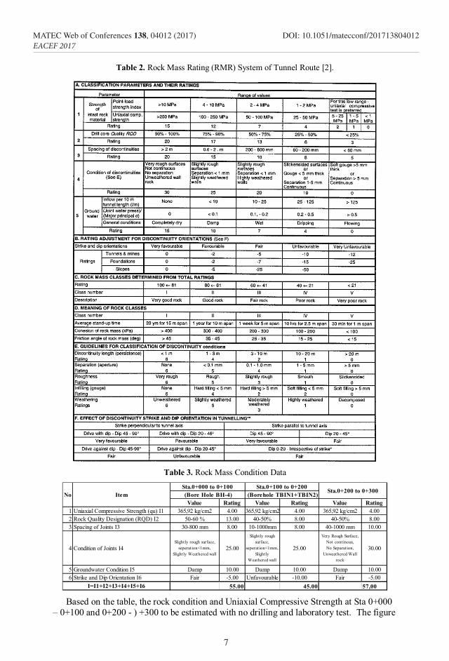
Table 2. Rock Mass Rating (RMR) System of Tunnel Route [2].
Table 3. Rock Mass Condition Data
Value Rating Value Rating Value Rating1 Uniaxial Compressive Strength (qu) I1 365,92 kg/cm2 4.00 365,92 kg/cm2 4.00 365,92 kg/cm2 4.002 Rock Quality Designation (RQD) I2 50-60 % 13.00 40-50% 8.00 40-50% 8.003 Spacing of Joints I3 30-800 mm 8.00 10-1000mm 8.00 40-1000 mm 10.00
4 Condition of Joints I4Slightly rough surface,
seperation<1mm, Slightly Weathered wall
25.00
Slightly rough surface,
seperation<1mm, Slightly
Weathered wall
25.00
Very Rough Surface, Not continous, No Separation,
Unweathered Wall rock
30.00
5 Groundwater Condition I5 Damp 10.00 Damp 10.00 Damp 10.006 Strike and Dip Orientation I6 Fair -5.00 Unfavourable -10.00 Fair -5.00
55.00 45.00 57,00
Sta.0+200 to 0+300
I=I1+I2+I3+I4+I5+I6
No ItemSta.0+000 to 0+100 (Bore Hole BH-4) (Borehole TBIN1+TBIN2)
Sta.0+100 to 0+200
Based on the table, the rock condition and Uniaxial Compressive Strength at Sta 0+000
– 0+100 and 0+200 - ) +300 to be estimated with no drilling and laboratory test. The figure
7
MATEC Web of Conferences 138, 04012 (2017) DOI: 10.1051/matecconf/201713804012EACEF 2017

of rock mass class compared to the theory of Rock mass classification, shows that the rock mass class is categorized as Rock Mass Class III which is classified as Sand Rock condition.
Fig. 5. (a) Supports are put if the rock condition is unstable, (b) Support Condition which is related to the Value of RMR.
The figure 6 indicates the support with a span length of 10 metres. Assuming the value of RMR (Rock Mass Rating) obtained from the result and relation of drilling test, the time known to resist the load will remain for 2 days and 4 years. The higher the RMR value, then the lesser the support can be or even without support. Besides that, the support can be given for more duration. For the two days duration may stand for two days, then shotcrete must be done. Meanwhile, the four years may last for four years, then shotcrete should also be done.
4.5 Horseshoe Tunnel Type
Fig. 6. Total Displacement for (a) Horseshoe and (b) Circle shaped tunnel. Abaqus, 2016.
The shape and size of the design cross-section derive firstly from the purpose of the tunnel (rail tunnel, road tunnel, sewer, water tunnel or pressure runnel for a hydropower station) and thus the required clearance gauge [7]. In this case, the use is for water tunnel for a hydropower station. The analysis has been done by numerical analysis using the finite element method based on Abaqus, a computer program used for the modelling. The result shows the maximum of total displacement of 34,0 x 10⁻³ meters for the modelling of the horse shaped tunnel. Meanwhile, the maximum total displacement of the circular shape tunnel result is 195,59 x 10⁻³ meters. This means that the model generated Horse hoe shaped displacement value due to the deformation are smaller than the circle shaped
8
MATEC Web of Conferences 138, 04012 (2017) DOI: 10.1051/matecconf/201713804012EACEF 2017

of rock mass class compared to the theory of Rock mass classification, shows that the rock mass class is categorized as Rock Mass Class III which is classified as Sand Rock condition.
Fig. 5. (a) Supports are put if the rock condition is unstable, (b) Support Condition which is related to the Value of RMR.
The figure 6 indicates the support with a span length of 10 metres. Assuming the value of RMR (Rock Mass Rating) obtained from the result and relation of drilling test, the time known to resist the load will remain for 2 days and 4 years. The higher the RMR value, then the lesser the support can be or even without support. Besides that, the support can be given for more duration. For the two days duration may stand for two days, then shotcrete must be done. Meanwhile, the four years may last for four years, then shotcrete should also be done.
4.5 Horseshoe Tunnel Type
Fig. 6. Total Displacement for (a) Horseshoe and (b) Circle shaped tunnel. Abaqus, 2016.
The shape and size of the design cross-section derive firstly from the purpose of the tunnel (rail tunnel, road tunnel, sewer, water tunnel or pressure runnel for a hydropower station) and thus the required clearance gauge [7]. In this case, the use is for water tunnel for a hydropower station. The analysis has been done by numerical analysis using the finite element method based on Abaqus, a computer program used for the modelling. The result shows the maximum of total displacement of 34,0 x 10⁻³ meters for the modelling of the horse shaped tunnel. Meanwhile, the maximum total displacement of the circular shape tunnel result is 195,59 x 10⁻³ meters. This means that the model generated Horse hoe shaped displacement value due to the deformation are smaller than the circle shaped
tunnel. Beside that the cross-section shape is also influenced by the selected construction process and the associated machinery; for example a tunnel boring machine can only bore a circular section [7].
4.6 A Comparison to TBM
The tunnel boring machine (TBM) is usually used for large size tunnel with consistent rock condition. The process of extracting the drilling machines are continuously used, being fitted with equipment that threw out the results of excavation at the same speed. Thus the drilling machine can run continuously. When the tunnel pass through loose soil layers, then the drilling machine needs to be equipped with a shield, so the progress cannot match the speed when through consistent rocks. Meanwhile for the soft soil, the use of the drilling machine will cause troubles. Because, the drilling machine may change its position (the soil does not hold the load of heavy drilling machine), which will compound the control of the tunnel. In such cases in the soft soil, the use of grouting before bypassed by the drilling Machine will be a must.
Fig. 7. Contour/geotechnical Relief of Lau Gunung Region, Dairi, North Sumatera. [4]
Fig. 8. Site condition and Modelling of Lau Gunung Hydropwoer Plant.
5 Conclusion The method of NATM consisting of preparatory work, surveying, drilling, charging, blasting, ventilating, mucking, scaling, shotcreting, and rock bolting. The function of the tunnel is made to drain the water that has been free of sediment to be streamed to the surge tank. Technical geological factors and geotechnical conditions are a major cause chosen
9
MATEC Web of Conferences 138, 04012 (2017) DOI: 10.1051/matecconf/201713804012EACEF 2017

NATM. Horseshoe shape displacement value is smaller than the circle. The construction of with NATM method is an indispensable engineering geological surveys regular to get the result of strength of the rock surveyed. Meanwhile, the cost consideration, especially the aspect of mobilization, implementation and maintenance, will be the factors considered in the method chosen. A special Acknowledgments goes to PT. Inpola Meka Energi in welcoming to conduct a preliminary study to one of the project owned. Besides that, special thanks to PT. PP (Persero), tbk, Construction & Investment for providing data and substantial information about the Lau Gunung Hydropower plant. Additionally, acknowledgement for Beijing Jiaotong University for support related to the paper and conference.
References 1. Arshad, R.A. Abdullah, A Review on Selection of Tunnelling Method and Parameters
Effecting Ground Settlement. Mal. Eng. Vo. 21 Bund 14. (2016) 2. Bieniawski Z.T., Engineering rock mass classifications. (John Wiley & Sons, New
York, 1989) 3. PT. PP, Buku Referensi untuk Kontraktor PP. (Gramedia Pustaka Utama Press, Jakarta,
2003) 4. PT. IME, Buku Geology Report of Proyek PLTA Lau Gunung. (Jakarta, 2016) 5. L.C Vydrova. Comparison of tunneling methods NATM and Adeco RS. (2015). 6. B. Maidl, M. Thewes, U. Maidl. Handbook of Tunneling Engineering: Volume I:
Structures and Methods. (Ernst & Sohn, Berlin, 2013) 7. B. Maidl, M. Thewes, U. Maidl Handbook of Tunneling Engineering: Volume II:
Basics and Additional Engineering Services for Design and Construction. (Ernst & Sohn. Berlin, 2014)
8. K. Haruyama, S. Teramoto, K. Taira. Construction of large cross-section double-tier Metropolitan. Inter-city Highway (Ken-O-Do) Ome Tunnel by NATM. Tun. & Und. Space Tech. 20. 111–119. (2005)
9. The International Tunneling Association (ITA). Guidelines for the design of tunnels. Tun. & Und. Space Tech., Vo. 3, pp. 237-249. https://www.ita-aites.org/media/k2/attachments/public/Tust_Vol_3_3_237-249.pdf (1988)
10. M.A. Wiweko. Pembuatan terowongan (Tunneling). www.pusdiklat-minerba.esdm.go.id/index.../335-pembuatan-terowongan-tunneling. (2015)
10
MATEC Web of Conferences 138, 04012 (2017) DOI: 10.1051/matecconf/201713804012EACEF 2017