the effect of out of plane perpendicular beams on the
TRANSCRIPT

Civil Engineering Infrastructures Journal 2021, 54(1): 75-92
DOI: 10.22059/ceij.2020.288767.1612
RESEARCH PAPER
The Effect of Out of Plane Perpendicular Beams on the Ductility Demand
of Steel Moment Framed Structures during Progressive Collapse
Ghassemieh, M.1*, Mortazavi, S.M.R.2 and Valadbeigi, A.3
1 Professor, School of Civil Engineering, College of Engineering, University of Tehran,
Tehran, Iran. 2 Assistant Professor, School of Civil Engineering, Shahid Rajaee Teacher Training
University, Tehran, Iran. 3 M.Sc., School of Civil Engineering, College of Engineering, University of Tehran,
Tehran, Iran.
© University of Tehran 2021
Received: 11 Sep. 2019; Revised: 03 Aug. 2020; Accepted: 16 Aug. 2020
ABSTRACT: Unexpected loading, induced by severe earthquake or blast, could cause
local damage to a structure. In this case, the structure has the potential of progressive
collapse phenomenon. Hence, further consideration is required to mitigate the
consequences of such loading. This study is aimed to evaluate the progressive collapse
capacity of steel moment frames with different heights under column removal conditions.
Seven and twelve story buildings modeled in different conditions in order to view effects
of various parameters like the out of plane frames, column removal location, and the
height of buildings in the results. One of the middle column and/or the corner columns is
removed in order to evaluate the effect of column removal location in response of
structures. The General Services Administration and the Department of Defense
guidelines are considered for defining load combination for the analysis of the collapse.
Nonlinear dynamic analysis is conducted in order to obtain the ductility demand of
structures when the out of plane effect is considered. The structures have welded cover
plate connections, designed for high-seismic zone area. For evaluating the response of the
structures, for each connection at the point of column removal, maximum vertical
displacement is measured. For Finite Element analysis, a sub-assemblage of structures is
modeled using ABAQUS software and the ability of beams deformation and it’s out of
plane effect is measured.
Keywords: Column Removal, Ductility, Finite Element Analysis, Nonlinear Dynamic
Analysis, Progressive Collapse.
1. Introduction
Progressive collapse happens due to the
failure of main structural components or
local failure of structural elements. This
complex phenomenon always accompanied
* Corresponding author E-mail: [email protected]
with large deformations and nonlinear
behavior of the structural elements.
Subsequently, the damaged structure via the
catenary action finds a new load path to
transfer the forces from failed region to the
stable one. Catenary action is an ability of
76 Ghassemieh et al.
beams to resist the vertical displacement
and can further help a damaged structure to
reach stability. The Catenary action can
somehow control the structural damage as
well as force redistribution from damaged
portion of the structure to the robust parts of
structure in order to avoid progressive
collapse. This capability also decreases the
bending force moment, rotation and vertical
deformation in the exterior beams of
structures.
US General Services Administration
guideline (GSA, 2003) and Department of
Defense guideline (DoD, 2016) are
recommending different analysis methods
for the structures in the progressive collapse
analysis. Those guidelines have their
specific load combination for nonlinear
analysis. In the methodology of the
progressive collapse, the impact of the
collapse (abnormal load) is usually
presented by column removal. Both
guidelines offer different locations for
column removal in external frame in order
to simulate the abnormal load conditions.
After column removal, the structure is
reanalyzed to find out whether the initial
damage could further extend to the stable
part of structure or not. Three types of
analysis procedure exist in the GSA and the
DoD. Those are linear elastic static (called
LSP analysis), nonlinear static (called NSP
analysis), and nonlinear dynamic (called
NDP analysis).
Marjanishvili and Agnew (2006)
investigated the advantages and
disadvantages of the above analytical
procedure in details. It was shown that the
most effective analysis procedure is
nonlinear dynamic analysis. More research
was conducted in order to prove that the
results from nonlinear analysis are more
realistic than results obtained from linear
analysis. More importantly, the impact
factor that exists in the GSA guideline in
consideration of dynamic effects, could be
decreased (Kim and Kim, 2009).
Several researchers investigated the
progressive collapse response of steel
moment frame and their connections.
Khandelwal and El-Tawil (2007) focused
on the ductility of special moment frame
structures subjected to progressive collapse.
They evaluated the ability of the deformed
structure through the catenary action. Their
results revealed that the ductility and
strength were discordantly influenced by an
increase in beam depth and also by growth
of the yield to ultimate strength ratio.
Lee et al. (2009) recommended
simplified nonlinear analysis methods for
the progressive collapse response in the
welded steel moment frame structures. The
methods presented the relevance between
the column load and the chord rotation of
the beams. Kim and An (2009) investigated
the influence of the catenary action on the
progressive collapse response of the steel
moment frame structures. Their results
indicate that the maximum displacement
caused by snap column removal would be
less when the catenary action is considered.
They also concluded that the influence of
the catenary action would be superior when
the constraint of lateral movement of the
structure is increased. This would be
achieved by using additional bays or braces.
Kim et al. (2009) used alternative load
path method recommended in the
aforementioned guidelines in order to
examine progressive collapse resistance of
the steel moment frame structures. Their
results indicate that the nonlinear dynamic
analysis has larger structural response. In
addition, it was shown that progressive
collapse potential increased when the
corner column was eliminated and this
potential was decreased as the story number
increased.
Khandelwal and El-Tawil (2011) used
the pushdown analysis in order to study the
soundness of building systems by launching
collapse conditions of a damaged system. It
was concluded that with regard to the
column removal, the dynamic impact
factors associated with it were lower than
the generally used. Li et al. (2012) assessed
the progressive failure of steel structures
numerically and they developed a
procedure for multi-scale analyses on

Civil Engineering Infrastructures Journal 2021, 54(1): 75-92 77
seismic damage and progressive failure and
seismic damage in steel buildings with
including meso-scale damage development.
Sadek et al. (2013) presented a
computational method of the response of
steel moment frame simulating a column
removal situation. Using the Finite Element
method of analysis and material
nonlinearity with shell and solid elements
and conducting fracture mechanics, they
obtained results that matched well with the
experimental results.
Li et al. (2013) carried out two full scale
experiments on connections with steel I-
beam to tubular column. They subjected the
connections to a column removal and they
observed two modes of failure; namely a
continuous flexural and an interrupted
flexural failure. Song et al. (2014)
performed experimental and numerical
study to study the progressive collapse of an
existing steel frame structure.
Yang and Tan (2013) conducted several
experiments of the behavior of the bolted
connection under column removal situation.
Their study presented the modes of the
failure of different connection types and
also the capacity of the connections to
deform in catenary action.
Mashahdali and Kheyroddin (2014)
numerically studied the progressive
collapse of the new hexagrid structural.
Their research focused on the collapse of 28
and 48 story buildings models. They
demonstrated that the new hexagrid system
has sufficient force redistribution during the
progressive collapse mechanism. Also in a
progressive collapse scenario, Kheyroddin
et al. (2014) proposed an easy method in
order to compute of the dynamic load
amplification factor due to sudden column
loss. Their concept was based on the kinetic
energy transfer criteria.
Guo et al. (2015) studied the response of
the flush endplate moment connection
subjected to column removal in the
composite frame. They also developed
Finite Element model in order to simulate
the experimental test. They found that the
progressive collapse of their system is
susceptible to the properties of bolts.
Tavakoli and Kiakojouri (2015)
investigated numerically the threat-
independent progressive collapse in the
steel moment frame structures. The
influence of the pertinent parameters such
as number of stories and location of primary
failure were discussed.
Dinu et al. (2016) investigated the
response of steel frame structures under the
removal of a central numerically as well as
experimentally. They found that the beam
ultimate rotation of the system was larger
than the deformation limit given in the
codes. Abdollahzadeh et al. (2016)
investigated the impacts of progressive
collapse on four story steel building with a
special moment frame system. They
assessed the rate of the collapse risk and the
reliability of the structure. Li et al. (2017)
conducted a small scale analysis with the
static push down. They revealed that the
catenary and the flexural actions are the
principal and primary source of the collapse
resisting.
Zhong et al. (2017) presented the anti-
progressive collapse performance of steel
frames with different connections subjected
to internal column removal. Different
modes of failure were observed for different
connections. Three dimensional Finite
Element models developed by Rahnavard et
al. (2018) in order to study the progressive
collapse of high rise steel frame structures
with different types of lateral systems
including regular and/or irregular plans.
From the obtained results, they made
certain recommendations in order to
prevent progressive collapse in future
designs.
Meng et al. (2018) studied the
progressive collapse behavior of steel
structures with different connections and
dissimilar spans. Their research contained
experimental as well as numerical study.
They concluded that, when the stiffness of
the beam and column are matching, then
performance of the anti-progressive
collapse mechanism can be improved. Lee
et al. (2018), using the energy based

78 Ghassemieh et al.
approach, evaluated the progressive
collapse behavior of the steel frame
structures with several connection types.
They demonstrated that the steel frame with
RBS connections were least sentient to
progressive collapse in comparison with the
other type of connections. Sensitivity
analysis was conducted by Rezaie et al.
(2018) and Kheyroddin et al. (2019); and by
following the GSA and DoD guidelines the
key elements of the progressive collapse
such as plan and height of the structure were
identified. Yavari et al. (2019) investigated
the effects of torsional irregularity together
with seismic evaluation on the progressive
collapse behavior of special steel moment
frames. They demonstrated that buildings
designed with greater torsional
irregularities have better resistance to the
progressive collapse.
As reported, most researchers only used
two dimensional analyses in order to
determine the progressive collapse behavior
of steel structures and therefore the
participation and influence of out of plane
frames are neglected in the analysis. The
main contribution of this research is to
investigate the out of plane effects on the
collapsing frames. It is included in the
nonlinear dynamic analysis to evaluate the
progressive collapse of special steel
moment resisting frames more realistically.
The results of nonlinear analysis obtained
from the GSA and the DoD guidelines are
compared in order to illustrate the role of
out of plane frame stiffness in the
progressive collapse potential. The
influence of different parameters such as the
position of column removal and the number
of stories that could influence the behavior
of steel moment structures during
progressive collapse are examined.
Furthermore, Finite Element analysis is
carried out to evaluate the performance of
flange plate connections. Numerical results
are compared with both guidelines
prediction of progressive collapse potential.
2. Analytical Procedure
2.1. Acceptance Criteria for Nonlinear
Analysis
In regards to the nonlinear dynamic
analysis, both GSA and DoD guidelines
consider ductility and maximum plastic
hinge for the criteria of progressive collapse
potential. Tables 1 and 2 depict the
complying criteria of steel beams and
columns for progressive collapse in
accordance with the GSA and the DoD
guidelines respectively. It must be pointed
out that here the definition of ductility is the
ratio of maximum displacement at the
column removal point to the yield
displacement and the rotation criterion is
calculated by proportioning the maximum
vertical displacement to the beam’s length.
2.2. Dynamic Analysis
The GSA recommends the following
load combination for the dynamic analysis
in every bay:
𝐷𝐿 + 0.25𝐿𝐿 (1)
where DL: is the dead load and LL: is the
live load.
In comparison with the GSA, the load
combination for the DoD guideline is
somehow different and it considers greater
load factor for DL and LL. For the DoD, the
wind load is also initiated in the load
combination; as follows:
Table 1. Acceptance criteria for nonlinear analysis in the GSA guideline Component Ductility Rotation (rad.)
Steel beams 20 0.21
Steel columns (Tension controls) 20 0.21
Steel columns (Compression controls) 1 -
Table 2. Acceptance criteria for nonlinear analysis in the DoD guideline Component Criteria
Steel beams Collapse prevention
Steel columns Life safety

Civil Engineering Infrastructures Journal 2021, 54(1): 75-92 79
(1.2𝐷𝐿 + 0.5𝐿𝐿) + 0.2𝑊𝐿 (2)
where WL: corresponds to wind load.
The following load criterion, as
recommended by Kim and Kim (2009) is
used for the dynamic analysis. First, column
axial force (P), bending moment (M) and
shear force (V) are calculated prior to the
column removal. Second, as it is shown in
Figure 1, the column is substituted by
balanced and equal loads in order to elude
from the unpleasant vertical displacement at
the point where the column is removed.
For this purpose, the gravity load and the
wind load as well as computed column
loads are increased linearly and
simultaneously until reaching their full
intensity in the fifth second. Column loads
remain unchanged for two seconds, while
the gravity and wind loads will stay the
same until the end of analysis. This step
allows the system to reach a stable
condition. In the final step, column forces
are suddenly removed in the seventh
seconds of the collapse time operation in
order to resemble the progressive collapse
event and perceive the dynamic influence of
the column removal in structure.
2.3. Structural Characteristics
In this study, seven and twelve stories
buildings are chosen to assess their
progressive collapse potential. Figure 2a
presents the structural plan for both
structures, while Figure 2b and 2c show the
elevation view of the analytical models.
Story height and bay size are set as 3 m and
5 m; respectively. Each structure contains
five bays in X direction and three bays in Y
direction. These buildings are designed
according to the AISC (2003) specification.
The location of the structures is assumed
to be in Tehran, Iran, which is regarded as a
highly seismic region. Special moment
resisting frame system is used for the lateral
system as well as gravity load resisting
system. The structural elements such as
columns and beams are designed with ST37
steel and the basic wind speed is considered
to be 100 km/h. The dead loads of 56.2 kPa
and 45 kPa are used for the floors and the
top roof; respectively. The wall loading of
32 kPa and 15 kPa are used for the external
and internal walls; respectively. The live
loading of 20 kPa, 30 kPa and 15 Kpa are
used for the floors, stairs and top roof;
respectively.
The structural sections of the building
models are presented in Tables 3 and 4.
2.4. Analytical Modeling
For dynamic analysis, the OpenSees
program is used for two-dimensional
modeling of the structure. The exterior
frame, as illustrated in Figure 2a, is
considered for the analysis purposes. For
modeling the structural elements, the beam
with hinges element of the program (called
BeamWithHinge Element) is employed
(Figure 3a). With this kind of element, the
plastic hinge is defined at the starting and
the finishing part of each column and beam
elements. In beam with hinges elements, the
nonlinear behavior of members must be
specified and determined at plastic hinge.
Therefore, the moment-rotation curvature
of beam and column sections with
considering the elastic and plastic effects
are defined using steel 01 material, which is
a bilinear material model and is provided in
the OpenSees (Figure 3b).
Table 3. Main structural sections for the seven story building
Column section Beam section Story number
Box 320×20 I330×160 1
Box 320×20 I330×160 2
Box 320×20 I330×160 3
Box 320×20 I330×160 4
Box 270×20 I330×120 5
Box 270×20 I330×120 6
Box 270×20 I320×100 7

80 Ghassemieh et al.
Table 4. Main structural sections for the twelve story building
Column section Beam section Story number
Box 350×25 I380×240 1
Box 350×25 I380×240 2
Box 350×25 I380×240 3
Box 350×25 I380×240 4
Box 320×20 I330×160 5
Box 320×20 I330×160 6
Box 320×20 I330×160 7
Box 320×20 I330×160 8
Box 270×20 I330×120 9
Box 270×20 I330×120 10
Box 270×20 I330×120 11
Box 270×20 I330×120 12
Fig. 1. The method of inserting loads
(a)
(b)

Civil Engineering Infrastructures Journal 2021, 54(1): 75-92 81
(c)
Fig. 2. Structural configuration of the models chosen: a) Structures plan; b) Seven story frame and; c) Twelve
story frame
(a)
(b)
Fig. 3. Opensees element and material: a) Beam with hinge element and; b) Steel01 material model

82 Ghassemieh et al.
The defined sections are assigned to the
hinges with section aggregator command.
As a definition of beam with hinges
element, the middle section of elements will
have an elastic behavior during analysis.
Two different scenarios are considered for
each frame. For the first case, the frame is
perceived without considering out of plane
stiffness, and in the other case, the frame is
modeled with considering out of plane
effect of vertical frames in 2D model to
evaluate such effect. The influence of out of
plane frames is considered by employing
equivalent springs. The springs are
regarded as the vertical stiffness of out of
plane frames. They are attached to the
intersection nodes of beams and columns in
the model. The post yield stiffness of the
structural elements is considered to be 2%
of the initial stiffness and for large
deformation analysis; the damping ratio is
assumed to be of 5% of the critical
damping.
3. Nonlinear Dynamic Analyses of
Structures
Nonlinear dynamic analyses are conducted
subjected to different states by removing
the corner column and the center column of
the structure in order to resemble the
progressive collapse. The vertical
displacement is evaluated at the position of
column removal; mainly because this
parameter plays an important role to
evaluate the collapse behavior as well as
ductility demand of structures. Plastic hinge
rotation of beams is also assessed and the
results are used to provide useful
comparison between guidelines criteria and
analyzed structural response. Each structure
is modelled with two different conditions;
with and without considering stiffness of
out of plane frames.
In Figures 4a and 4b, the vertical
displacement due to the time history for the
seven story structure with and without the
inclusion of out of plane frame stiffness are
depicted based on the GSA loading
recommendation. In Figures 4c and 4d, the
same graphs are also presented for the
twelve story structure. Figure 5 shows also
the same parameters based on the DoD
instructions for both the seven story and the
twelve story structure. The red graph shows
the state of the model that the out of plane
effect is not included and the blue graph
shows the frame which considers the out of
plane effect of frames.
It can be concluded from Figures 4 and 5
that the maximum vertical displacement is
decreased when the number of floors rises.
Thus, the results are largely dependent upon
the number of stories. The vertical
displacement of structures in case of corner
column removal is greater than the models
where their center column is removed. This
conclusion is valid to both circumstances
(with and without considering out of plane
effect). The results show that considering
out of plane effect has significant effects on
the response of the structures; and structural
demand is decreased if their effects are
taken into the account.
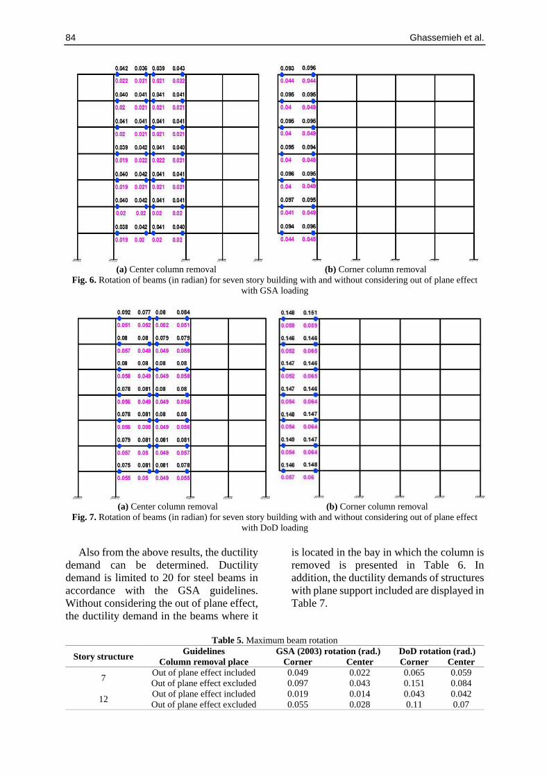
Beams rotation (in radian) for seven
story models with and without considering
out of plane effect due to the GSA (2003)
guideline is presented in Figure 6. The
numbers in purple color demonstrate the
rotations in which out of plane effect
excluded and the numbers in black color
present the rotations in which out of plane
effect included. As it is shown, the beams
rotation at the bay where the center column
is removed, does not exceeded the
maximum specified rotation given by the
GSA (2003) guideline (0.21 rad). For the
corner column removal scenario, the plastic
hinge rotation increased; although the
acceptance criteria still satisfied. When the
structure is analyzed subjected to the DoD
load combination, the end beams rotation
increased compared with the GSA (2003)
results (Figure 7). The maximum beam
rotation in Figure 7 is 15% whereas this
number is 10% in Figure 6. Both beam
rotations are less than the maximum
acceptance criterion of the GSA which is
21%. In summary, maximum beam
rotations of each model is presented in
Table 5.

Civil Engineering Infrastructures Journal 2021, 54(1): 75-92 83
(a) Seven story (center column removed) (b) Seven story (corner column removed)
(c) Twelve story (center column removed) (d) Twelve story (corner column removed)
Fig. 4. Vertical displacement for seven and twelve story models with GSA (2003)
(a) Seven story (center column removed) (b) Seven story (corner column removed)
(c) Twelve story (center column removed) (d) Twelve story (corner column removed)
Fig. 5. Vertical displacement for seven and twelve story models due to the DoD loading
-25
-20
-15
-10
-5
0
5
0 5 10 15 20
Ver
tical
dis
pla
cem
ent
(cm
)
Time (sec)
With Out-of-Plane Stiffness
Without Out-of-Plane Stiffness
-50
-40
-30
-20
-10
0
10
0 5 10 15 20Ver
tical
dis
pla
cem
ent
(cm
)
Time (sec)
With Out-of-Plane Stiffness
Without Out-of-Plane Stiffness
-15
-10
-5
0
5
0 5 10 15 20
Ver
tical
dis
pla
cem
ent
(cm
)
Time (sec)
With Out-of-Plane Stiffness
Without Out-of-Plane Stiffness
-40
-30
-20
-10
0
10
0 5 10 15 20
Ver
tical
dis
pla
cem
ent
(cm
)
Time (sec)
With Out-of-Plane Stiffness
Without Out-of-Plane Stiffness
-50
-40
-30
-20
-10
0
10
0 5 10 15 20Ver
tical
dis
pla
cem
ent
(cm
)
Time (sec)
With Out-of-Plane Stiffness
Without Out-of-Plane Stiffness
-75
-60
-45
-30
-15
0
15
0 5 10 15 20Ver
tical
dis
pla
cem
ent
(cm
)
Time (sec)
With Out-of-Plane Stiffness
Without Out-of-Plane Stiffness
-40
-30
-20
-10
0
10
0 5 10 15 20
Ver
tical
dis
pla
cem
ent
(cm
)
Time (sec)
With Out-of-Plane Stiffness
Without Out-of-Plane Stiffness
-60
-45
-30
-15
0
15
0 5 10 15 20Ver
tical
dis
pla
cem
ent
(cm
)
Time (sec)
With Out-of-Plane StiffnessWithout Out-of-Plane Stiffness
84 Ghassemieh et al.
(a) Center column removal (b) Corner column removal
Fig. 6. Rotation of beams (in radian) for seven story building with and without considering out of plane effect
with GSA loading
(a) Center column removal (b) Corner column removal
Fig. 7. Rotation of beams (in radian) for seven story building with and without considering out of plane effect
with DoD loading
Also from the above results, the ductility
demand can be determined. Ductility
demand is limited to 20 for steel beams in
accordance with the GSA guidelines.
Without considering the out of plane effect,
the ductility demand in the beams where it
is located in the bay in which the column is
removed is presented in Table 6. In
addition, the ductility demands of structures
with plane support included are displayed in
Table 7.
Table 5. Maximum beam rotation
DoD rotation (rad.) GSA (2003) rotation (rad.) Guidelines Story structure
Center Corner Center Corner Column removal place
0.059 0.065 0.022 0.049 Out of plane effect included 7
0.084 0.151 0.043 0.097 Out of plane effect excluded
0.042 0.043 0.014 0.019 Out of plane effect included 12
0.07 0.11 0.028 0.055 Out of plane effect excluded

Civil Engineering Infrastructures Journal 2021, 54(1): 75-92 85
Table 6. Ductility demand without considering out of plane effect
Corner column removal Center column removal
Story
structure
Yield disp.
(mm)
Max. disp.
(mm) Ductility
Yield disp.
(mm)
Max. disp.
(mm) Ductility
GSA
7 72 410 5.69 55 190 3.45
12 60 280 4.67 51 135 2.65
DoD
7 72 665 9.24 55 375 6.81
12 60 510 8.5 51 345 6.76
Table 7. Ductility demand with considering out of plane effect
Corner column removal Center column removal
Story
structure
Yield disp.
(mm)
Max. disp.
(mm) Ductility
Yield disp.
(mm)
Max. disp.
(mm) Ductility
GSA (2003)
7 62 135 2.18 50 100 2
12 52 94 1.81 45 70 1.55
DoD
7 62 315 5.08 50 240 4.8
12 52 225 4.33 45 205 4.55
As presented in the above tables, the
ductility demand values are not over the
specified value set by the GSA (2003).
However, the ductility demand values for
the DoD loading analyses illustrates a large
discrepancy with respect to the GSA (2003)
results. As expected, the DoD guideline
load pattern requests larger ductility
demand in comparison with the GSA
(2003) guideline. It is concluded from
Tables 6 and 7 that a ductility ratio obtained
from corner column removal is larger than
the state of center column removal.
Where the influence of out of plane
frames considered in the models, the
ductility demand decreases significantly in
comparison with the situation in which the
out of plane frames are ignored. It is also
observed that the story number has the
reverse relation with the ductility demand
and with increasing the story number, the
ductility demand is reduced. It could be
mentioned that none of the ductility demand
of structures exceeds the acceptance
criterion of 20. It can be deduced that
structures with moment resisting frame
system have a reasonable reserve functional
abilities when as an initiation of progressive
collapse is subjected to column removal due
to the investigated guidelines.
4. Finite Element Modeling of Beam-
Column Connections
4.1. Characteristics of Models
The welded flange plate connection
(Ghobadi et al., 2009), as shown in Figure 8
is selected in order to study the progressive
collapse potential.
Fig. 8. Welded flange plate connection

86 Ghassemieh et al.
For increasing the capacity of beam
section in the beam-column connection area
cover plates are added instead of reducing
beam section. As a result, a plastic hinge
will not be formed at the connection zone
and brittle fracture of connection will be
prevented. Beam and column sections of
models are shown in Table 8. In Finite
Element modeling, beams are modeled with
their real length and columns are modeled
with 1 m height. Therefore, the boundary
condition can be applied at the ends of the
column and then the catenary action can be
started. Cover plate dimensions for both
models are shown in Figure 9. For seven
story and twelve story models, the top plate
has thickness of 20 mm and the bottom plate
thickness is 15 mm.
4.2. Material Properties
In the Finite Element model, in order to
capture the realistic connection behavior, it
is most proper to describe the material in the
form of true stress and strain correlation.
Since mostly the material data is available
in the form of engineering stress and strain
relationship, hence it is essential to change
material data from engineering to true
relationship. The following equations can
be utilized in order to do the conversion.
𝜎 = 𝜎𝑛𝑜𝑚 (1 + 𝜀𝑛𝑜𝑚) (3)
𝜀 = ln(1 + 𝜀𝑛𝑜𝑚) (4)
in which 𝜎: is the true stress, 𝜀: is the true
strain, 𝜎𝑛𝑜𝑚 : is the nominal engineering
stress and 𝜀𝑛𝑜𝑚: is the nominal engineering
strain.
In ductile materials such as mild steel,
fracture initiation could start by plasticity.
Ductile fracture will arise as a consequence
of vast necking and plastic deformation in
the necked vicinity. When the specified
equivalent plastic strain is reached, the
model presumes the damage begins. Since
the triaxial test data for the mild steel
materials used in this study is not available,
hence the triaxial effect could not be
documented. Thus, the fracture strain
defined in the ductile criterion is
independent of hydrostatic stress; however,
previous researchers (Ghobadi et al., 2009;
Mehr and Gobadi, 2017; Jazany and
Ghobadi, 2018) have demonstrated that the
ductility of steel rests considerably on the
stress triaxiality.
Table 8. Geometrical properties
Member length (m) Section (mm) Member Story structure
5 I 330×160 Beam Section 7
1 Box 320×20 Column Section
5 I 380×240 Beam Section 12
1 Box 400×20 Column Section
Top plate Top plate
Bottom plate Bottom plate
(a) Seven story building (b) Twelve story building
Fig. 9. Cover plate dimensions

Civil Engineering Infrastructures Journal 2021, 54(1): 75-92 87
Therefore, model parameters needed for
ductile criterion that have been calibrated to
a specific experiment cannot be considered
as material properties and may not be able
to correctly simulate ductile fracture in
circumstances which vary mainly from the
prototype experiment used for model
calibration. It should be specified that this
fracture criterion is also dependent on mesh
size. The steel yield stress was taken as
244.8 Mpa and the ultimate stress was taken
as 444 Mpa. The ultimate equivalent plastic
strain value is taken as 0.16.
4.3. Finite Element Modeling
ABAQUS Finite Element software is
used in order to perform numerical
modeling of the connections. Two exterior
bays of a perimeter moment frame and
corner bay of exterior frame are considered
for analysis (Figure 2). For all models
considered, both material as well as
geometric nonlinearity are considered.
Material nonlinearity is being considered in
the ABAQUS software using standard
metal plasticity material model; which is
based on an incremental plasticity
formulation. Three dimensional solid brick
elements with twenty nodes (three degrees
of freedom for each node which includes
the secondary effects) were used for the
modeling of the connection area and three
dimensional solid brick elements with eight
nodes were used for the beam and column
elements. For verifying an approach of the
present study, comparison of results
between Khandelwal and El-Tawil (2007)
study and this study is undertaken, as shown
in Figure 10.
Based on the results from Figure 10, it
can be concluded that the results obtained
from present study is quite close to the
results of Khandelwal and El-Tawil (2007);
and the differences is quite insignificant.
Four different Finite Element models are
generated in order to investigate four
different conditions. They are middle beam-
column connection with and without
transverse beam and corner beam-column
connection with and without transvers
beam. Sub-assemblages are assumed
located at the first story.
(a)
(b)
Fig. 10. First story Force-Displacement relation for non RBS connections without transverse beam: a)
Khandelwal and El-Tawil (2007) and; b) Present analysis
-200
300
800
1300
1800
0 0.25 0.5 0.75 1 1.25 1.5 1.75 2
Forc
e (k
N)
Vertical displacement (m)
Analytical Model
88 Ghassemieh et al.
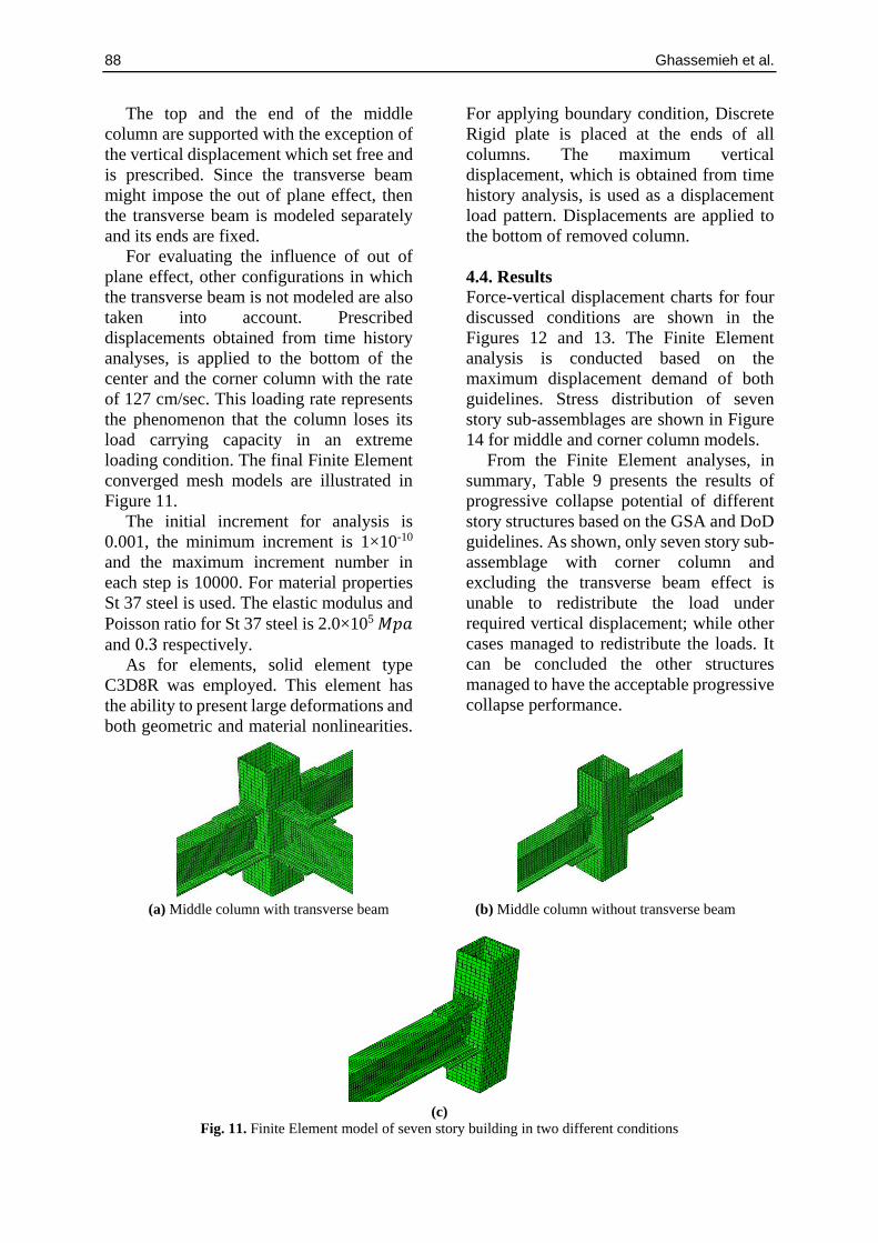
The top and the end of the middle
column are supported with the exception of
the vertical displacement which set free and
is prescribed. Since the transverse beam
might impose the out of plane effect, then
the transverse beam is modeled separately
and its ends are fixed.
For evaluating the influence of out of
plane effect, other configurations in which
the transverse beam is not modeled are also
taken into account. Prescribed
displacements obtained from time history
analyses, is applied to the bottom of the
center and the corner column with the rate
of 127 cm/sec. This loading rate represents
the phenomenon that the column loses its
load carrying capacity in an extreme
loading condition. The final Finite Element
converged mesh models are illustrated in
Figure 11.
The initial increment for analysis is
0.001, the minimum increment is 1×10⁻¹⁰
and the maximum increment number in
each step is 10000. For material properties
St 37 steel is used. The elastic modulus and
Poisson ratio for St 37 steel is 2.0×10⁵ 𝑀𝑝𝑎
and 0.3 respectively.
As for elements, solid element type
C3D8R was employed. This element has
the ability to present large deformations and
both geometric and material nonlinearities.
For applying boundary condition, Discrete
Rigid plate is placed at the ends of all
columns. The maximum vertical
displacement, which is obtained from time
history analysis, is used as a displacement
load pattern. Displacements are applied to
the bottom of removed column.
4.4. Results
Force-vertical displacement charts for four
discussed conditions are shown in the
Figures 12 and 13. The Finite Element
analysis is conducted based on the
maximum displacement demand of both
guidelines. Stress distribution of seven
story sub-assemblages are shown in Figure
14 for middle and corner column models.
From the Finite Element analyses, in
summary, Table 9 presents the results of
progressive collapse potential of different
story structures based on the GSA and DoD
guidelines. As shown, only seven story sub-
assemblage with corner column and
excluding the transverse beam effect is
unable to redistribute the load under
required vertical displacement; while other
cases managed to redistribute the loads. It
can be concluded the other structures
managed to have the acceptable progressive
collapse performance.
(a) Middle column with transverse beam (b) Middle column without transverse beam
(c)
Fig. 11. Finite Element model of seven story building in two different conditions

Civil Engineering Infrastructures Journal 2021, 54(1): 75-92 89
Fig. 12. Seven story building beam-column connection models
Fig. 13. Twelve story beam-column connection models
(a) Stress distribution for middle column with
transverse beam at 61 cm vertical displacement
(b) Stress distribution for middle column without
transverse beam 51 cm vertical displacement
0
50
100
150
200
250
300
350
400
0 10 20 30 40 50 60
Fo
rce
(kN
)
Vertical displacement (cm)
Middle Column with lateral Stiffness Middle Column without lateral Stiffness
Corner Column with lateral Stiffness Corner Column without lateral Stiffness
0
100
200
300
400
500
600
0 10 20 30 40 50 60
Fo
rce
(kN
)
Vertical displacement (cm)
Middle Column with Lateral Stiffness Middle Column without Lateral Stiffness
Corner Column with Lateral Stiffness Corner Column without Lateral Stiffness

90 Ghassemieh et al.
(c) Stress distribution for corner column without transverse beam at 43 cm vertical displacement
Fig. 14. Stress contour for seven story beam-column connections
Table 9. Progressive collapse potential of structures
DoD GSA (2003) Guideline Story structure
Center Corner Center Corner Column removal place
No No No No With transverse beam 7
No Yes No No Without transverse beam
No No No No With transverse beam 12
No No No No Without transverse beam
5. Conclusions
This study focused on the progressive
collapse behavior in the special moment
resisting framed structures. The influence
of the pertinent parameters such as the story
number, position of column removal,
impact of out of plane frames on maximum
vertical displacement and ductility demand
of beams are investigated. The analyses
carried out using the General Services
Administration as well as the Department of
Defense guidelines; and the differences
between the results are assessed.
Results reveal that the special steel
moment resisting frames designed for
lateral loads have a reasonable performance
during progressive collapse simulation. It is
concluded that when the structure suffers
from losing its corner column, it becomes
more vulnerable in comparison with the
structure losing one of its central columns.
It is observed that there is a relation between
the number of stories and the potential of
progressive collapse. As the story number
increased, the ductility demand as well as
beams rotation reduce indicating the
decrease of potential of progressive
collapse. The structures are analyzed due to
the GSA (20030 and the DoD guidelines
and their progressive collapse potential are
illustrated.
Moreover, the effect of out of plane
frame is evaluated independently. As
explained, out of plane have an effective
influence over the results and decreased the
potential of progressive collapse. In some
cases, due to this affect, the ductility
demand decreased by more than one-half.
The importance of considering out of plane
and its influence on the maximum vertical
displacement is demonstrated.
This advantage could considerably
reduce the ductility demand of structures.
Based on the Finite Element analysis, the
structures showed that they have more
resistance to progressive collapse than it
was expected regarding both guidelines.
Only one sub-assemblage showed not
having the ability of the demand required
and it loses its capacity before reaching the
required displacement. In some cases, the

Civil Engineering Infrastructures Journal 2021, 54(1): 75-92 91
results are dissimilar from guidelines
expectations and therefore further
investigation is required.
6. References
Abdollahzadeh, G., Nemati, M. and Avazeh, M.
(2016). "Probability assessment and risk
management of progressive collapse in strategic
buildings facing blast loads", Civil Engineering
Infrastructure Journal, 49(2), 427-338.
American Institute of Steel for Construction (AISC).
(2003). Load resistance factor design
specification for structural steel buildings,
Chicago, IL.
Department of Defense (DoD) (2016). "Unified
facilities criteria (Ufc) design of buildings to
resist progressive collapse", Washington D.C.
Dinu, F., Marginean, I. Dubina, D. and Petran I.
(2016). "Experimental testing and numerical
analysis of 3D steel frame system under column
loss", Engineering Structures, 113(15), 59-70.
Ghobadi, M.S., Mazroi, A. and Ghassemieh, M.
(2009). "Cyclic response characteristics of
retrofitted moment resisting connections",
Journal of Constructional Steel Research, 65(3),
586-598.
Ghobadi, M.S., Ghassemieh, M., Mazroi, A. and
Abolmaali, A. (2009). "Seismic performance of
ductile welded connections using T-stiffener",
Journal of Constructional Steel Research, 65(4),
766-775.
Guo, L., Gao, S. and Fu, F. (2015). "Structural
performance of semi-rigid composite frame
under column loss", Engineering Structures,
95(15), 112-126.
Jazany, R.A. and Ghobadi, M.S. (2018). "Seismic
evaluation and upgrading details of plate-
reinforced moment-resisting connections",
Journal of Constructional Steel Research, 150,
230-248.
Khandelwal, K. and El-Tawil, S. (2007). "Collapse
behavior of steel special moment resisting frame
connections", Journal of Structural Engineering,
133(5), 646-655.
Khandelwal, K. and El-Tawil, S. (2011). "Pushdown
resistance as a measure of robustness in
progressive collapse analysis", Engineering
Structures, 33(9), 2653-2661.
Kheyroddin, A., Gerami, M. and Farshad, M. (2014).
"Assessment of the dynamic effect of steel frame
due to sudden middle column loss", The
Structural Design of Tall and Special Buildings,
23, 390-402.
Kheyroddin, A., Sharbatdar, M.K. and Farahani, A.
(2019). "Assessment effect of structural height
on the location of key element in progressive
collapse of RC structures", Civil Engineering
Infrastructure Journal, 52(1), 41-58.
Kim, H.S., Kim, J. and An, D. (2009). "Development
of integrated system for progressive collapse
analysis of building structures considering
dynamic effects", Advances in Engineering
Software, 40(1), 1-8.
Kim, J. and An, D. (2009). "Evaluation of
progressive collapse potential of steel moment
frames considering catenary action", The
Structural Design of Tall and Special Buildings,
18(4), 455-465.
Kim, J. and Kim, T. (2009). "Assessment of
progressive collapse-resisting capacity of steel
moment frames", Journal of Constructional Steel
Research, 65(1), 169-179.
Kim, T. and Kim, J. (2009). "Collapse analysis of
steel moment frames with various seismic
connections", Journal of Constructional Steel
Research, 65(6), 1316-1322.
Lee, C., Kim, S., Han, K. and Lee, K. (2009).
"Simplified nonlinear progressive collapse
analysis of welded steel moment frames",
Journal of Constructional Steel Research, 65(5),
1130-1137.
Lee, S.Y., Noh, S.Y. and Lee, D. (2018). "Evaluation
of progressive collapse resistance of steel
moment frames designed with different
connection details using energy-based
approximate analysis", Sustainability, 10(10), 1-
28.
Li, H., Cai, X., Zhang, L., Zhang, B. and Wang, W.
(2017). "Progressive collapse of steel moment-
resisting frame subjected to loss of interior
column: Experimental tests", Engineering
Structures, 150, 203–220.
Li, L., Wang, W., Chen, Y. and Lu, Y. (2013).
"Experimental investigation of beam-to-tubular
column moment connections under column
removal scenario", Journal of Constructional
Steel Research, 88, 244-255.
Li, Z.X., Jiang, F.F. and Tang, Y.Q. (2012). ‘Multi-
scale analyses on seismic damage and
progressive failure of steel structures’, Finite
Elements in Analysis and Design, 48(1), 1358-
1369.
Marjanishvili, S. and Agnew, E. (2006).
"Comparison of various procedures for
progressive collapse analysis", Journal of
Performance of Constructed Facilities, 20(4),
365-374.
Mashhadiali, N. and Kheyroddin, A. (2014).
"Progressive collapse assessment of new
hexagrid structural system for tall buildings",
The Structural Design of Tall and Special
Buildings, 23(12), 947-961.
Mehr, S.M. and Ghobadi, M.S. (2017). "Seismic
performance of retrofitted WFP connections
joined to box column using ribs", Journal of
Constructional Steel Research, 137, 297-310.
Meng, B., Zhong, W. and Hao, J. (2018). "Anti-
collapse performances of steel beam-to-column

92 Ghassemieh et al.
assemblies with different span ratios", Journal of
Constructional Steel Research,140, 125-138.
Rahnavard, R., Fathi Zadeh Far, F., Hosseini, A. and
Suleiman, M. (2018). "Nonlinear analysis on
progressive collapse of tall steel composite
buildings", Case Studies in Construction
Materials, 8, 359-379.
Rezaie, F., Fakhradini, S.M. and Ghahremannejad
M. (2018). "Numerical evaluation of progressive
collapse potential in reinforced concrete
buildings with various floor plans due to single
column removal", Civil Engineering
Infrastructures Journal, 51(2), 405-424.
Sadek, F., Main A., Lew, H. and El-Tawil, S. (2013).
"Performance of steel moment connections under
a column removal scenario II: Analysis", Journal
of Structural Engineering, 139(1), 108-119.
Song, B.I., Giriunas, K.A. and Sezen, H. (2014).
"Progressive collapse testing and analysis of a
steel frame building", Journal of Constructional
Steel Research, 94, 76-83.
Tavakoli, H. and Kiakojouri, F. (2014). "Threat-
independent column removal and fire-induced
progressive collapse: Numerical study and
comparison", Civil Engineering Infrastructures
Journal, 48(1), 121-131.
US General Services Administration (GSA). (2003).
"Progressive collapse analysis and design
guidelines for new federal office buildings and
major modernization projects", Washington D.C.
Yang, B. and Tan, K.H. (2013). "Experimental tests
of different types of bolted steel beam-column
joints under a central-column-removal scenario",
Engineering Structures, 54, 112-130.
Yavari, H., Ghobadi, M.S. and Yakhchalian, M.
(2019). "Progressive collapse potential of
different types of irregular buildings located in
diverse seismic sites", Heliyon, 5(1), 01137.
Zhong, W., Meng, B. and Hao, J. (2017).
"Performance of different stiffness connections
against progressive collapse", Journal of
Constructional Steel Research, 135, 162-175.
This article is an open-access
article distributed under the
terms and conditions of the
Creative Commons Attribution
(CC-BY) license.