the effect of a t6 heat treatment on the fretting wear of a sic particle-reinforced a356 aluminum...
TRANSCRIPT
Ž .Wear 238 2000 110–119www.elsevier.comrlocaterwear
The effect of a T6 heat treatment on the fretting wear of a SiCparticle-reinforced A356 aluminum alloy matrix composite
Rong Chen ), Akira Iwabuchi, Tomoharu ShimizuDepartment of Mechanical Engineering, Faculty of Engineering, Iwate UniÕersity, Morioka 020, Japan
Received 15 March 1999; received in revised form 11 October 1999; accepted 12 October 1999
Abstract
The fretting wear behavior of an A356 aluminum alloy reinforced by 15 vol.% 10 mm silicon carbide particle with and without T6Ž . Ž .heat treatment is investigated, when tested against a bearing steel ball SJU2-QT at different applied loads 5–20 N and fretting cycles
Ž 4 6 .10 –10 cycles under a ballrflat contact. It is proven that T6 heat treatment of composites offers better fretting wear resistancecompared with that without heat treatment. The effect of load on the fretting wear damage reveals that the wear loss volume of thecomposite is increased with the increase of the load. At higher load, the aluminum matrix in the composite is transferred from thecomposite to the counterface steel ball. However, at low load, the SiC particles in the composites have high probability to abrade the steelball seriously. After long cycle duration, the plastic deformation of the composite becomes more serious, meanwhile, the debristransferred from the steel ball to the composite is accumulated. The heap volume becomes larger, and the net wear volume becomes smallor even negative. q 2000 Published by Elsevier Science S.A. All rights reserved.
Keywords: Metal matrix composites; Particulate-reinforced MMCs; Fretting wear; Fretting damage; Heat treatment
1. Introduction
Particle-reinforced aluminum alloy matrix compositesare recognized to have more improved elastic modulus,
w xtensile and fatigue strength over monolithic alloys 1–3 .Liquid stirring method in the manufacturing of these mate-rials can achieve uniform distribution of particles in com-posite. High specific modulus and strength, combined withan ability to be near net shaped by conventional castingprocess, make these materials attractive for use in dynami-
w xcally loaded applications 4,5 . However, welding of thesematerials is difficult without decreasing their mechanicalperformance. Mechanical connection using bolts, for ex-ample, can result in fretting wear problems which arecaused by vibration with small amplitude at contactingsurfaces. As a result, attention has been given to frettingwear of particle-reinforced aluminum alloy matrix compos-ites.
Aluminum alloy matrix composites are generally re-ported to show improved sliding wear resistance compared
) Corresponding author. Tel.: q81-19-621-6417; fax: q81-19-621-6417; e-mail: [email protected]
w xwith their monolithic alloys 6–10 . The study on thefretting wear of metal matrix composites is comparatively
w x w xless. Sumita et al. 11 and Maruyama et al. 12 hadreported improved fretting fatigue performance for bothwhisker and particulate-reinforced aluminum alloy matrix
w xcomposites. McColl et al. 13 examined a 2124-T4 alu-minum alloy reinforced with 20 vol.% of 3 mm SiCparticles, tested it against a medium carbon steel, andfound it to be superior to the monolithic alloy over fretting
Ž 6 .wear distances up to ;80 m 1=10 cycles . Recentw xstudy 14 found that although the composite possessed
significant advantages over the monolithic alloy up to;1=106 fretting cycles, the artificial ageing treatmentroutes had little influence on the wear rate of the compos-ite. In contrast, the effect of the anodizing surface treat-ment was most marked.
Further studies are required to clarify the effect of heattreatment on the fretting wear of an aluminum alloy rein-forced with SiC particles at several affecting factors suchas applied normal load and fretting cycles. In this study,we compared the fretting wear behavior of Al–Si alu-minum alloy reinforced by 15 vol.% SiC particles compos-ites with and without T6 heat treatment at different normal
Ž . 6loads 5–20 N up to 1=10 cycles. The most attention is
0043-1648r00r$ - see front matter q 2000 Published by Elsevier Science S.A. All rights reserved.Ž .PII: S0043-1648 99 00328-2
( )R. Chen et al.rWear 238 2000 110–119 111
paid on the effects of T6 heat treatment on the frettingwear behavior of the composites.
2. Experiment
2.1. Materials
The material used for fretting wear is A356 aluminumalloy matrix composites reinforced by 15 vol.% 10 mmSiC particles, supplied by Dulacan Aluminum. This mate-rial was made by molten liquid aluminum stirring method,and then cast into an ingot. One part of specimens wastested in T6 heat treatment, it was solidified at temperature535"58C for 6 h and quenched in 808C water, then agedat a temperature of 2008C for 5 h in air. The counterface
Ž .steel ball is a commercial bearing steel ball JIS:SJU2-QTafter quench. Material specifications are listed in Tables 1and 2. The tested surface of the composite was polished bythe SiC abrasive papers up to 1000 grits. The polishedspecimens and the bearing steel ball were then cleanedultrasonically in acetone for 10 min.
2.2. Fretting wear tests
The fretting apparatus used in the present work wasw xnoted elsewhere 15 . The normal load was applied to the
upper specimen by a dead weight through a loading leverusing a ball bearing. The linear oscillating slip was appliedto the upper specimen by an eccentric device. The fric-tional force was measured with strain gauges and ampli-fiers, and the data was recorded into a PC through ArDboard. The friction coefficient was automatically calcu-lated. The sampling time was 2.0 ms.
The experiment was conducted at the sliding amplitudeof about 80"4 mm, and frequency of 10 Hz. The appliednormal loads were 5, 10 and 20 N, and the fretting cycleswere 104, 105 and 106, respectively. Temperature wasabout 20"38C, and relative humidity was about 55"10%in the laboratory air.
The composite material was a lower disc specimen witha diameter of 20 mm and a height of 8 mm. The upperspecimen was an SJU2-QT steel ball with diameter of 9mm. At the fretting cycles of 104 and 105, the experimentwas taken 10 times in different places under the samecondition for getting an average value. However, at 106
cycles, because the scatter of experiment data becomes
Table 1Ž .Chemical compositions of A356 and SUJ2-QT bearing steel ball mass%
Materials Al Fe C Si Mn Cr Mg Cu
A356 91.8 0.3 – 7.0 0.3 – 0.3 0.3SUJ2-QT – 96.77 1.03 0.25 0.50 1.45 – –
Table 2Yield strength, hardness and roughness of fretting specimens
Materials Yield strength Hardness, Roughness,Ž . Ž . Ž .MPa Hv 5 Nr15 s Ra mm
SiCprA356 175 89 0.4Ž .as-receivedSiCprA356 205 105 0.4Ž .T6SUJ-2 – 802 0.1Ž .ball, Ds9 mm
small, the experiment was only taken five times to saveexperiment time.
2.3. Fretting scar assessment
Fretting scar area was like an ellipse, the two diametersin the two perpendicular direction of the ellipse weremeasured by the optical microscope with an accuracy of 1mm. The wear scar area was calculated according to theform of ellipse.
Heap and loss volumes were obtained, respectively, bythe surface roughness profilometer with an interval of 5mm for a scar. The former was caused by plastic deforma-tion and adhered debris and the latter by wear damage,respectively. They are volumes above and below the origi-nal unworn specimen surface as a datum region, as shownin Fig. 1. Net wear volume losses were obtained from lossvolume subtracted by the heap volume.
3. Results
3.1. Coefficient of friction
Coefficient of friction of composites with and withoutheat treatment at normal loads of 5, 10 and 20 N is shownin Fig. 2. At low normal load of 5 N, the coefficient offriction at the beginning is low, about 0.16 and 0.25 for
Ž . Žheat treatment white point and no heat treatment dark.point , respectively. It increases with the fretting cycles,
and at about 300 cycles, it reaches the maximum value andthen drops slightly and keeps unchanged. At a normal loadof 10 N, it shows the same trend, however, the coefficientof friction at the beginning becomes larger, about 0.28 and0.34 for heat treatment and no heat treatment, respectively.At a load of 20 N, the coefficient of friction is large fromthe beginning and basically keeps unchanged, about 0.45.
Heat treatment has the effect on the coefficient offriction dependent on the normal load. The composite withheat treatment shows a low coefficient of friction duringthe initial fretting stages. At a load of 10 N, the coefficientof friction with heat treatment is lower by about 0.1 thanthat without heat treatment. However, when the load

( )R. Chen et al.rWear 238 2000 110–119112
Fig. 1. The 3-D surface roughness trace of a SiCprAl without T6 heat treatment at 5 N and 106 cycles.
reaches 20 N, the coefficient of friction with and withoutheat treatment is almost the same.
3.2. Wear scar area
The configuration of the wear scar is like an ellipse asshown in Fig. 3. There are mounds of debris around thewear scar perimeter. In some specimens, brown debriswere found to exist on the surface of the wear scar, as
Ž .shown in Fig. 3 b . The wear area is larger at this case,about 1.5 times the usual one. The probability for this kindof wear area to occur is about 23.3% for the low load of 5N, 4% for 10 N and only 2% in the case of 20 N. It isrelated with the contact surface and wear mechanism atdifferent loads as will be discussed in Section 4.2.
Fig. 2. Coefficient of friction of the composite with and without heattreatment at different loads vs. fretting cycles.
Wear scar area at 104, 105 and 106 fretting cycles withand without heat treatment vs. the normal load is shown inFig. 4. The scatter of data of wear area is about 25% of
Ž .Fig. 3. The configuration of the fretting wear scar: a usual fretting wearŽ .scar and b brown debris surrounding the surface.

( )R. Chen et al.rWear 238 2000 110–119 113
Fig. 4. Wear scar area of the composites with and without T6 heattreatment vs. normal load.
their average value. Composites without T6 heat treatmenthave larger wear area, especially when the normal loadsare large at 10 and 20 N and with an increase in frettingcycles. The wear area without heat treatment is obviouslyincreased with normal load, however, that with heat treat-ment was unchanged with normal load, except at 20 N and106 fretting cycles.
3.3. Wear Õolumes
The net wear volume at different normal loads vs.fretting cycle is presented in Fig. 5. The scatter of experi-ment data of heap and loss volume is about 30% of theiraverage value. Due to the presence of adhered debriswithin the scars, these data will underestimate the true lossvolumes.
Almost for all the specimens at different normal loads,the net wear volume reaches the maximum for test dura-tion up to 105 cycles. When the test duration is increasedto 106 cycles, the net wear volume is decreased continu-ally and even becomes negative for some specimens at lowloads of 5 and 10 N. The net wear volume is negative at
Fig. 5. Net wear volume of the composite with and without T6 heattreatment vs. fretting wear cycles.
Ž 4 .the initial stage 10 cycles for the composite with heattreatment at low load of 5 N.
Heat treatment exhibits obvious effects on the change ofthe net wear volume. At the short test duration at 104 and105 cycles, the net wear volume without heat treatment islarger. When the test duration is up to 106 cycles, since itis easy for the composite without heat treatment to be in alarger scale of plastic deformation, the net wear volumebecomes smaller at that time.
3.4. Heap Õolumes
The heap volume is due to the plastic deformationaround the scar perimeter, and including a degree of theadhered debris above the specimen surface. To gain animpression of the degree of the heap volume, the heapvolume vs. fretting cycles is shown in Fig. 6. At short testduration before 105 cycles, the heap volume is unchanged,however, it increases obviously when at 106 cycles, be-cause the plastic deformation on the surface of compositeis serious at long test duration.
The heap volume becomes smaller by heat treatment. Itis very obvious during the long test duration at 106 cycles.The heap volume will, to some extent, be close to thevalue of loss volume, or larger than it, which makes thenet wear volume become negative.
3.5. Fretting wear of counterface steel ball
The fretting wear behavior of counterface steel ball isclosely related with the applied normal load. The typicalfretting wear surfaces of steel ball wear against the com-posite with T6 heat treatment at different loads of 5 and 20N are shown in Fig. 7. At a low load 5 N, the steel ballsuffered serious fretting wear, the loss parts are veryobvious, and the wear area is also large. On the contrary,at a high load of 20 N, the surface of the steel ball showsthat only a little loss volume occurs.
The composition analysis by EDX of the wear surfaceof steel ball at different loads is shown in Table 3. It
Fig. 6. Heap volume of the composite with and without T6 heat treatmentvs. fretting wear cycles.

( )R. Chen et al.rWear 238 2000 110–119114
5 Ž . Ž .Fig. 7. The 3-D surface roughness trace of the steel ball wear against the composite with T6 heat treatment at 10 cycles and at a 5 and b 20 N.
reveals that in low load of 5 N, Fe element at the frettingsurface dominates. The content of Fe element is about68.27 wt.% and Al element is only about 4.92 wt.%, whichmeans the transferred volume of Al debris to the steel ballis less. However, at high load of 20 N, the wear surface ofsteel ball is mainly Al element, about 48.84 wt.%. Thecontent of Fe element is only 33.78 wt.% at this case. Sothat at high load, the aluminum in the composite is trans-ferred to the surface of steel ball. It is proven by thesurface analysis of steel ball by EDX shown as in Fig. 8, itshows that there is a block of aluminum oxide adhesive onthe wear surface of steel ball according to the distributionof Al, O and Fe elements.
3.6. Microscopy
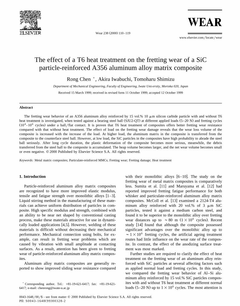
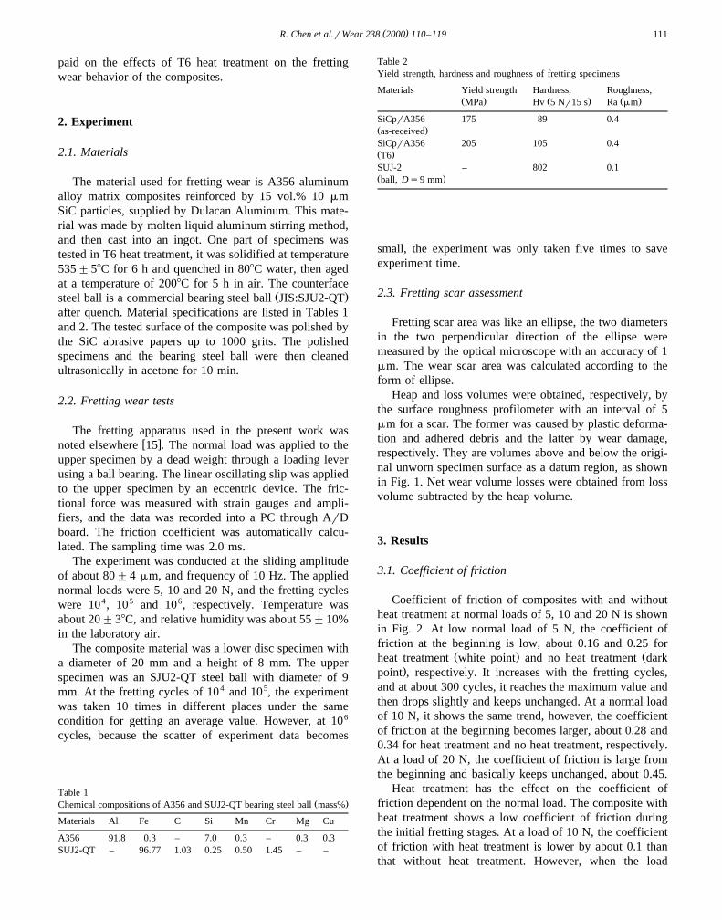
SEM views of a composite specimen show that frettingwear damage is more serious in the edge of the wear scar,as shown in Fig. 9. A creak is also formed at the defectplace in the center of the fretting surface, as shown in Fig.10. After the creak formed under the oscillated plasticdeformation, the crack may propagate and at last results indelamination of materials. Finally, a trough is left in thecenter of the fretting surface by delamination. The originalresource of the crack more easily occurs in a place wherethe SiC particles aggregate due to the non-uniform desper-ation of the SiC particles.
Table 3The content of chemical element in the fretting wear surface of the steelball against the composite with T6 heat treatment at 105 cycles
Ž . Ž .Applied load Fe wt.% Al wt.% OthersŽ . Ž .N Si, Cr, Ni
5 68.27 4.92 26.8120 33.78 48.84 17.38
The scar area with heat treatment is smaller, there arerelatively less cracks and the troughs can be found infretting surface. The degree of damage is also relativelymild. At 104 cycles for both cases, damage is found toeasily occur in the edge of fretting scar. At 105 cycles,severe damage occurs in the whole fretting wear surfacewithout heat treatment. The depth and area of existingtroughs are increased with the increasing of fretting cycles,meanwhile, the scar perimeter suffers a heavy deformationunder the normal load, which makes the heap of moundwide and high for both composite with and without heattreatment.
4. Discussion
4.1. Effect of heat treatment
The hardness and yield strength of composite are in-creased after T6 heat treatment as shown in Table 2, it isadvantageous in improving deformation–adhesion resis-tance, restricting the initial transfer of composite debris tothe counterface. Fig. 2 reveals that at low load of 5 N,composite with heat treatment has the obviously lower
Ž .coefficient of friction in the initial stages 400 cycles , andat middle load of 10 N, the coefficient of friction with heattreatment is also smaller. However, when the load isincreased to 20 N, even heat treatment loses its resistanceto deformation–adhesion. As a result, the coefficient offriction does not show the trend from a low to high value,it reaches the average value at the beginning, and keepsunchanged, and the value is the same for both heat treat-ment and without heat treatment.
In the fretting wear of the composite against steel ball,the aluminum particle debris is easily transferred from the

( )R. Chen et al.rWear 238 2000 110–119 115
Fig. 8. The fretting wear surface and the chemical element composition analysis of the steel ball against the composite with T6 heat treatment at 105 cyclesand 20 N.
composite to the steel ball, as shown in Table 3. The highhardness and yield strength of the composite by T6 heattreatment would have the advantage of preventing theformation of aluminum debris, and decreasing its transferto the surface of steel ball will decrease the adhesive wearbetween the fretting wear surface.
4.2. Effect of normal contact load
The SiC particles in the composite abrade the counter-face steel seriously at low load for its high hardness in the
w xsliding wear 16 . For the same reason, when fretting wearis conducted between the composite and the steel ball at
low load, the particles may abrade the steel ball seriously.However, since the stroke of fretting wear is only 80 mm,and the axle length of the fretting wear scar is only about
Ž .300 mm see Fig. 3 , in the contact surface between thecomposite and the steel ball the number of particle isdifferent due to the non-uniform distribution of the SiCparticle. When the number of the particle is larger, theparticles abrade steel ball seriously. The trough is formed
Ž .in the surface of ball, as shown in Fig. 7 a . As a result,the contact wear surface between ball and composite isincreased, which makes the wear scar area larger like the
Ž .case in Fig. 3 b . It occurred on the probability of 23.3% atthe low load of 5 N, only 4% and 2% at loads of 10 and 20
( )R. Chen et al.rWear 238 2000 110–119116
Fig. 9. The fretting wear surface of the composites showing the fretting damage is serious at the edge of the wear scar at 5 N and 105 cycles with T6 heattreatment.
N. Because the probability of the distribution of SiC is thesame at different loads, we can infer that at high load, theparticle may fracture and loss some ability to abrade thesteel ball. Fig. 11 shows the fretting surface and composi-
Ž .tion analysis of the composite at low load of 5 N a andŽ .high load of 20 N b , at low load, the intensity of Fe
element is larger than that at high load. The distribution ofFe element is close to that of Si element related with thedistribution of SiC particle, it proves that SiC particleabrade the steel ball at low load. At high load, although theintensity of Si element is high, it means the SiC particlesexist in this area, the particle may fracture at high load, it
may lose the ability to abrade the ball, so the intensity ofFe element is very small on high load.
When the normal load is increased to reach the fracturestrength of the particle, the particles begin to fracture.Besides, the particle near the contact surface may easilyinduce the nucleation of cracks due to the interfacedebonding between particle and matrix than monolithicaluminum alloy, as shown in Fig. 12. These cracks maypropagate and connect to form the subsurface cracks infretting wear process. At higher load of 20 N, the net wearvolume is not increased obviously. The composite suffersheavy plastic deformation which makes the heap volume
Fig. 10. The fretting wear surface of the composites showing the damage also occurs in the center of fretting area at 10 N and 105 cycles without T6 heattreatment.

( )R. Chen et al.rWear 238 2000 110–119 117
much larger, then the net wear volume is not increasedobviously.
4.3. Effect of fretting cycles
In Fig. 5, the net wear volume of composite is themaximum at 105 cycles. The net wear volume is defined aswear loss volume subtracted by heap volume. So when theincrease of the heap volume is larger than that of lossvolume, the net wear volume will decrease. At frettingwear before 105 cycles, the wear loss volume dominates,however, at longer fretting duration, the plastic deforma-tion of aluminum alloy is accumulated, and become moreserious, as shown in Fig. 1. The heap volume is increased
about three times at 106 cycles compared to that at 105
cycles, as shown in Fig. 6. As a result, although the wearloss volume increased after 105 cycles, the net wear vol-ume decreased, as shown in Fig. 5.
5. Conclusions
The following conclusions could be obtained form thefretting wear behavior of a particle-reinforced aluminummatrix composite against a bearing steel ball.
Ž .1 T6 heat treatment of composites offers better fret-ting wear resistance compared with that without heat treat-ment, including low coefficient of friction, small net fret-ting wear and heap volumes.
5 Ž . Ž .Fig. 11. The fretting wear surface and composition analysis of the composite without T6 heat treatment at 10 cycles and a 5 and b 20 N.

( )R. Chen et al.rWear 238 2000 110–119118
Ž .Fig. 11 continued.
Ž .2 The loss and heap volumes of the composite areincreased with increase in normal load. At higher load, the
Fig. 12. Schematic diagram of a model of fretting wear damage of aSiCprA356 composite and steel ball dependent on normal loads.
aluminum matrix in the composite is transferred from thecomposite to the steel ball.
Ž .3 After long test duration, the heap volume due to theplastic deformation and the degree of debris transferredfrom the steel ball to composite is larger than the lossvolume, especially for the composite without heat treat-ment.
Ž .4 At low load, the SiC particles in the composite havethe larger probability to abrade the steel ball seriously.
Acknowledgements
The author, Rong Chen, wish to thank Japan Society forthe Promotion of Science for providing JSPS fellowship
( )R. Chen et al.rWear 238 2000 110–119 119
for the research. Many thanks are due to Mr. K. Mat-sumoto and S. Takahashi in the workshop in Iwate Univer-sity who helped prepare the specimens.
References
w x1 H. Sekine, R. Chen, A combined microstructure strengthening analy-Ž .sis of SiCprAl metal matrix composites, Composite 6 1995 183–
188.w x2 R. Chen, G.D. Zhang, Casting defects and properties of cast A356
alloy reinforced with SiC particulates, Compos. Sci. Technol. 4Ž .1993 511–556.
w x3 P.M. Singh, J.J. Lewandowski, Effects of heat treatment and rein-forcement size on reinforcement fracture during tension testing of aSiCp discontinuously reinforced aluminum alloy, Metall. Trans. A
Ž .24 1993 2531–2543.w x4 L. Wei, J.C. Huang, Influence of heat treatment and hot working on
fracture toughness of cast aluminum base composites, Mater. Sci.Ž .Technol. 9 1993 841–852.
w x5 B. Venkataraman, G. Sundararajan, The sliding wear behavior ofAl–SiC particulate composites: 1. Macrobehaviour, Acta Mater. 44Ž .1996 451–460.
w x6 A.T. Alpas, J. Zhang, Effect of SiC particulate reinforcement on theŽ .dry sliding wear of aluminum–silicon alloys A356 , Wear 155
Ž .1992 83–104.w x7 A.T. Alpas, J.D. Embury, Sliding and abrasive wear behavior of an
Ž .aluminum 2014 SiC reinforced composite, Scr. Metall. Mater. 24Ž .1990 931–935.
w x Ž8 A.T. Alpas, J. Zhang, Effect of microstructure particulate size and.volume fraction and counterface materials on the sliding wear
resistance of particulate-reinforced aluminum matrix composites,Ž .Metall. Trans. A 25A 1994 969–983.
w x9 O.P. Modi, B.K. Prasad, A.H. Yegneswaran, M.L. Vaidya, Dry
sliding wear of squeeze cast aluminum alloy–silicon carbide com-Ž .posites, Mater. Sci. Eng., A 151 1992 235–245.
w x10 B. Manish Roy, B. Venkataraman, V.V. Bhanuprasad, Y.R. Maha-jan, G. Sundarajan, The effect of particle reinforcement on thesliding wear behavior of aluminum matrix composites, Metall. Trans.
Ž .A 22A 1992 2833–2847.w x11 M. Sumita, N. Maruyama, K. Nakazawa, Role of second phases in
fretting fatigue strength in a SiC whisker reinforced aluminum alloyŽ .composite, J. Jpn. Inst. Met. 57 1993 1141–1148.
w x12 N. Maruyama, M. Sumita, K. Nakazawa, Fatigue and fretting fatiguebehavior of A2024-T6 composite materials reinforced with 20 vol.%
Ž .SiC particles, J. Jpn. Inst. Met. 57 1993 1268–1274.w x13 I.R. McColl, S.J. Harris, G.J. Spurr, Fretting wear of a fine particu-
late reinforced aluminum alloy matrix composite against a mediumŽ .carbon steel, Wear 197 1996 179–191.
w x14 I.R. McColl, S.J. Harris, Q. Hu, G.J. Spurr, P.A. Wood, Influence ofsurface and heat treatment on the fretting wear of an aluminum alloy
Ž .reinforced with SiC particles, Wear 203–204 1997 507–515.w x15 A. Iwabuchi, The role of oxide particles in the fretting wear of mild
Ž .steel, Wear 151 1991 301–311.w x16 R. Chen, A. Iwabuchi, T. Shimizu, H.S. Shin, H. Mifune, The
sliding wear resistance behavior of NiAl and SiC particles reinforcedŽ .aluminum alloy matrix composites, Wear 213 1997 175–184.
Rong Chen, received his PhD in Engineering from Shanghai Jiao TongUniversity in China in 1989. Then, he became a lecturer and an associateprofessor at Shanghai Jiao Tong University. Now he is an assistantprofessor at Iwate University in Japan. His major research areas are metalmatrix composites, tribology and mechanics.
Akira Iwabuchi, is a professor of Iwate University with a PhD inEngineering. Major research areas are tribology, mechanical working andmechanical materials.
Tomoharu Shimizu, is an associate professor of Iwate University, with aPhD in Engineering. Major research areas are tribology and mechanics.