the early evolution of the ebs in safety assessments
TRANSCRIPT

THE EARLY EVOLUTION OF THE EBS IN SAFETY ASSESSMENTS
Includes PEBS deliverable D1.1 (and D1.2)
A PEBS WP1 REPORT Version October 2012, updated after HLEC comments SKB ANDRA NAGRA ENRESA GRS
BGR

The research leading to these results has received funding from the European Atomic Energy Community's Seventh Framework Programme (FP7/2007-2011) under grant agreement n° 249681

Preface The main aim of the project PEBS (Long-term Performance of the Engineered Barrier System) is to evaluate the sealing and barrier performance of the EBS with time. The focus is to study the processes in the early evolution of the repository system and to evaluate the impact of the processes on the long-term safety functions. The final objective of the project is to improve the treatment of the early transients in long-term safety assessments for HLW/Spent fuel. This report covers the work performed within PEBS WP 1 and describes current treatment of the early evolution of the EBS in safety assessments from a number of European national programs (state of the art). The description starts with an overview of the repository concepts. Both HLW and spent fuel repositories are covered as well as both clay and crystalline host rocks. This is followed by an overview of the assessment methodology used in the different programs. One important aspect of the methodology is the definition an application of safety functions. Basically, safety functions are a tool that is used for the evaluation of the performance as a function of time for individual repository components. The uncertainties in the early evolution in the EBS can generally evaluated with aid of the safety functions. The main part of the report describes the treatment of the THMC-process in the EBS and the potential impact on the safety functions. Some examples of processes are:
Saturation of buffer Buffer homogenisation Buffer upward expansion Movement of the canister in the deposition hole Homogenisation after loss of bentonite mass Thermal evolution Iron/clay interaction Chemical evolution of the buffer including alteration of the clay Effects of gas on the hydration process
A key purpose of the report is to identify the uncertainties in the process understanding and in the treatment of the processes in the assessment. The significance of the identified uncertainties on the evaluation of the safety functions is also discussed. The report also summarizes the uncertainties and defines a number of cases or “scenarios” that will be assessed further within the PEBS project. Despite the differences in repository concepts, the safety functions defined for the engineered clay barriers are similar. The key processes occurring in the EBS in the early evolution of the repository that may affect the long the long-term performance are identical for all concepts on a fundamental level. However, the significance as well as the treatment of the processes in the safety assessment can differ between the concepts. The key processes identified are:
Water uptake in clay components of the EBS Mechanical evolution Alteration of the hydro-mechanical properties
These processes will be the main topic for further assessments within the project. The details in the cases will be discussed further within the project. The report covers PEBS deliverable D1.1 and D1.2. D1.2 is also presented as a separate volume. This version of the report has been updated to cover comments from the HLEC.

1 Table of contents
Preface ..................................................................................................................................................... 3 1 Table of contents ............................................................................................................................. 4 2 Introduction ..................................................................................................................................... 6
2.1 The PEBS project .................................................................................................................... 6 2.2 Analysis of system evolution during early post closure period: Impact on long-term safety functions .............................................................................................................................................. 7
3 Sweden ............................................................................................................................................ 8 3.1 Repository concept .................................................................................................................. 8 3.2 Safety assessment methodology .............................................................................................. 8 3.3 Safety Functions .................................................................................................................... 11
3.3.1 Definition of safety functions, indicators and criteria ................................................... 11 3.3.2 Quantities for safety function indicators ....................................................................... 12 3.3.3 Derivation of safety functions, indicators and criteria .................................................. 12 3.3.4 Safety function indicator criteria are not the same as design premises ......................... 12 3.3.5 Safety functions for containment ................................................................................... 12 3.3.6 Summary of safety functions related to containment .................................................... 14 3.3.7 Safety functions for retardation ..................................................................................... 15
3.4 Early evolution of the EBS .................................................................................................... 16 3.4.1 Methodology ................................................................................................................. 16 3.4.2 Assessment of the buffer evolution during the excavation/operational period and the first 1,000 years after repository closure and the initial period of temperate domain from the reference glacial cycle ................................................................................................................... 20
3.5 Identified uncertainties .......................................................................................................... 37 3.5.1 Thermal evolution of the near field ............................................................................... 37 3.5.2 Saturation of buffer ....................................................................................................... 37 3.5.3 Piping Erosion ............................................................................................................... 38 3.5.4 Homogenisation after loss of bentonite mass ................................................................ 38 3.5.5 Swelling and swelling pressure ..................................................................................... 38 3.5.6 Buffer chemical evolution ............................................................................................. 38 3.5.7 Summary of issues ......................................................................................................... 39
4 France ............................................................................................................................................ 40 4.1 Repository concept ................................................................................................................ 40
4.1.1 The Meuse / Haute-Marne site and the Callovo-Oxfordian clay layer .......................... 40 4.1.2 Overall design of the repository .................................................................................... 41 4.1.3 Spent fuel disposal cell .................................................................................................. 42
4.2 Safety assessment methodology ............................................................................................ 44 4.2.1 Basic Input Data ............................................................................................................ 45 4.2.2 Functional Analysis and System Requirements ............................................................ 46 4.2.3 Design based on Functions and Requirements .............................................................. 47 4.2.4 Phenomenological Analysis of Repository Situations ................................................... 48 4.2.5 Normal and Altered Evolution Scenarios ...................................................................... 48 4.2.6 Qualitative Safety Assessment ...................................................................................... 50 4.2.7 Overall Performance Calculation .................................................................................. 50
4.3 Safety Functions .................................................................................................................... 51 4.4 Early evolution of the EBS .................................................................................................... 53
4.4.1 Thermal processes ......................................................................................................... 53 4.4.2 Hydraulic/gas processes ................................................................................................ 54 4.4.3 Chemical processes ....................................................................................................... 55 4.4.4 Mechanical processes .................................................................................................... 58
4.5 Identified uncertainties .......................................................................................................... 59
4.5.1 Uncertainties on hydraulics processes ........................................................................... 59 4.5.2 Uncertainties on mechanical behaviour in contact with the metal elements ................. 59 4.5.3 Uncertainties in accounting for the mechanical effect of gases inside Argillites and swelling clay .................................................................................................................................. 59 4.5.4 Uncertainties over thermo-mechanical effects .............................................................. 60 4.5.5 Uncertainty concerning the technologies implemented in the repository: swelling clay seals and engineered barriers ......................................................................................................... 61 4.5.6 Summary of issues ......................................................................................................... 62
5 Switzerland .................................................................................................................................... 63 5.1 Repository concept ................................................................................................................ 63 5.2 Safety assessment methodology ............................................................................................ 63 5.3 Safety Functions .................................................................................................................... 65 5.4 Process evaluation of the near field ....................................................................................... 66
5.4.1 The resaturation period (0 to 100 years) ........................................................................ 67 5.4.2 100 to 10,000 years ....................................................................................................... 72 5.4.3 Beyond 10,000 years ..................................................................................................... 73
5.5 Identified uncertainties .......................................................................................................... 74 5.5.1 Thermo-hydraulic evolution of the buffer ..................................................................... 74 5.5.2 Hydro-mechanical evolution of the buffer .................................................................... 74 5.5.3 Chemical evolution of the buffer ................................................................................... 74 5.5.4 Summary of issues ......................................................................................................... 74
6 Spain .............................................................................................................................................. 75 6.1 Repository concept ................................................................................................................ 75 6.2 Safety assessment methodology ............................................................................................ 76 6.3 Safety Functions .................................................................................................................... 78
6.3.1 Main safety functions .................................................................................................... 78 6.3.2 Safety functions and safety requirements ...................................................................... 78 6.3.3 Safety functions and requirements of the buffer ........................................................... 79
6.4 Early evolution of the bentonite buffer ................................................................................. 80 6.4.1 THM evolution of the bentonite buffer ......................................................................... 80 6.4.2 Geochemical evolution of the bentonite buffer ............................................................. 85
6.5 Identified uncertainties .......................................................................................................... 86 6.5.1 THM evolution of the bentonite buffer ......................................................................... 86 6.5.2 Geochemical evolution of the bentonite buffer ............................................................. 86 6.5.3 Summary of issues ......................................................................................................... 87
7 Germany ........................................................................................................................................ 88 7.1 Preliminary concept for a clay repository ............................................................................. 88 7.2 Safety assessment methodology ............................................................................................ 90
8 Definition of cases/scenarios to be studied ................................................................................... 92 8.1 Introduction ........................................................................................................................... 92 8.2 Water uptake in clay components of the EBS ....................................................................... 92
8.2.1 Overview ....................................................................................................................... 92 8.2.2 Process description ........................................................................................................ 93 8.2.3 Uncertainties .................................................................................................................. 93
8.3 Mechanical evolution ............................................................................................................ 93 8.3.1 Overview ....................................................................................................................... 93 8.3.2 Process description ........................................................................................................ 93 8.3.3 Uncertainties .................................................................................................................. 94
8.4 Alteration of the hydro-mechanical properties ...................................................................... 94 8.4.1 Overview ....................................................................................................................... 94 8.4.2 Process description ........................................................................................................ 95 8.4.3 Uncertainties .................................................................................................................. 95
8.5 Cases to be studied in PEBS .................................................................................................. 95 9 References ..................................................................................................................................... 97

2 Introduction
2.1 The PEBS project
The main aim of the project PEBS (Long-term Performance of the Engineered Barrier System) is to evaluate the sealing and barrier performance of the EBS with time, through development of a comprehensive approach involving experiments, model development and consideration of the potential impacts on long-term safety functions. The experiments and models cover the full range of conditions from initial emplacement of wastes (high heat generation and EBS resaturation) through to later stage establishment of near steady-state conditions, i.e. full resaturation and thermal equilibrium with the host rock. These aspects will be integrated in a manner that will lead to a more convincing connection between the initial transient state of the EBS and its long-term state that provides the required isolation of the wastes. The work proposed within the project builds on existing knowledge and experience generated during recent years and supported by ongoing national and EC research programmes. The project pretends to provide a more complete description of the THM and THM-C (thermo-hydromechanical-chemical) evolution of the EBS system, a more quantitative basis for relating the evolutionary behaviour to the safety functions of the system and a further clarification of the significance of residual uncertainties for long-term performance assessment. The importance of uncertainties arising from potential disagreement between the process models and the laboratory and in situ experiments to be performed within PEBS, and their implications for extrapolation of results will be reviewed, with particular emphasis on possible impacts on safety functions. In addition to the scientific-tech. aim, the consortium will spread the essential results to the broad scientific community within the EC, China and Japan, use its expertise for public information purposes and promote knowledge and technology transfer through training. The PEBS project consists of seven Work Packages:
WP 1: Analysis of system evolution during early post closure period, Impact on long-term safety functions
WP 2: Experimentation on key EBS processes and parameters WP 3: Modeling of short-term effects and extrapolation to long-term evolution WP 4: Analysis of impact on long term safety WP B: China-Mock-Up WP 5: Dissemination WP 6: Project Management
The current report covers the work performed within WP 1.
2.2 PEBS Work Package 1
According to the PEBS Description of Work, the work in WP 1 is broken down into six tasks: Task 1.1 Identify important processes during the early evolution of the EBS. This task involves a listing of the processes that are considered in description of the evolution of the EBS in safety assessments. This task will also review the outcome of the NF-Pro project. The listing will give input to the expectations from the experiments done in WP2. Task 1.2 Describe the current treatment of the early evolution of the EBS in long-term safety assessments for HLW and spent nuclear fuel. This task will deal with how the processes described in 1) are treated in the assessments, which types models, assumptions and boundary conditions are used. This task is closely connected with the work in WP3. Task 1.3 Discuss how the short-term transients will/may affect the long-term performance and the safety functions of the repository. The purpose of this task is to connect the processes to the safety functions

in the repository – ie what impact will a process have on the overall performance of the repository. This task will be continued within WP4. Task 1.4 Identify the merits and shortcomings of the current treatment. This task will make a summary about the uncertainties related to the processes as well as to the treatment of the processes. This includes uncertainties in boundary conditions, data and in the conceptual models. Task 1.5 Discuss the needs for additional studies of these issues and how they can support future assessments. Based on the results of 4), lists of issues that can be handled by the PEBS project will be generated. These lists will give guidance to the work in WP2 and WP3. Task 1.6 Define “scenarios” related to events in the early evolution of the EBS. This task is an integration of the all the previous. The purpose is to define “cases” of EBS evolution that can be treated in WP4 The work in WP1 will progress during the first 12 months of the PEBS project. After that the assessment activities will be handled in WP4. The next section describes how the Tasks where handled within the project. Two deliverables were defined for the WP: D1.1: List of issues D1.2: List of scenarios and cases to be studies D1.1 is covered by listed uncertainties from the national safety assessments and can be found in sections: 3.5, 4.5, 5.5and 6.5. D1.2 is documented in chapter 8.
2.3 Analysis of system evolution during early post closure period: Impact on long-term safety functions
The early period of repository evolution is characterized by an elevated temperature together with strong thermal and hydraulic gradients (possibly mechanical and chemical as well). The duration of this period is very short in the view of the entire operational timeframe of the repository. However, the processes occurring during this period may have an impact on the performance of the barriers in a longer timescale. The objectives of WP 1 in the PEBS project is to identify the important processes, describe how they are treated in currently in long –term safety/performance assessments, discuss how the short-term transients will/may affect the long-term performance and the safety functions of the repository and to consider the key uncertainties in the current treatment. Task 1.1 – 1.3 was covered by a summary of the treatment of the early evolution of the EBS in safety assessments with examples from Sweden, France, Switzerland and Spain (and possibly a brief description of how the issues are treated in Germany). This includes a discussion on how the early evolution of the EBS could affect the long-term safety functions. Information outside of the national safety reports was not specifically covered by the WP. This was partly due to the limited resources of the project, but more importantly that it is up to the national safety assessment programs to judge which type of information that should go into the assessment. Some recent information may therefore be missing, especially for the programs where the safety assessments are a few years old. Task 1-4 and 1-5 is covered by the discussion of uncertainties in the different assessments. The merits and shortcomings of the current treatment of the processes in the assessments are not covered directly. However, the merit of the current treatment of a process is generally that that particular treatment was selected by the assessment team and the shortcoming is the identified uncertainties. Based on the current treatment of the processes remaining uncertainties in the conceptual understanding, the mathematical formulations and the input data can be identified. The identified uncertainties should be the basis for future study and could serve as a guide to WP2 and WP3 in the FORGE project. This does not mean that this report will define the work on WP2 and WP3. The overall experiments and modelling tasks have been defined prior to PEBS by the needs from the national programs. The uncertainties identified in WP1 are meant to serve as guidance for which parameters should be studied and how results should be interpreted.

According to Task 1-6, the product of WP1 should be a list of “scenarios” or cases related to events in the early evolution of the EBS that should be an integration of the entire study. The list should serve as an input to the analysis of impact on long-term safety and guidance for repository design and construction that will be performed in WP 4. The term “scenario” has a specific definition in certain programs. To avoid confusion, this document uses the more general term “case”. The cases are discussed chapter 8. The objective is still to address cases of relevance for the long-term safety of a repository.
3 Sweden
3.1 Repository concept
Several decades of research and development has led SKB to put forward the KBS-3 method for the final stage of spent nuclear fuel management. In this method, copper canisters with a cast iron insert containing spent nuclear fuel are surrounded by bentonite clay and deposited at approximately 500 m depth in groundwater saturated, granitic rock, see Figure 1. The purpose of the KBS-3 repository is to isolate the nuclear waste from man and the environment for very long times. Around 12,000 tonnes of spent nuclear fuel is forecasted to arise from the currently approved Swedish nuclear power programme (where the last of the 10 operating reactors is planned to end operation in 2045), corresponding to roughly 6,000 canisters in a KBS-3 repository.
Figure 1 The KBS-3 concept for disposal of spent nuclear fuel
3.2 Safety assessment methodology
The SR-Site report /SKB 2011/ constitutes a part of SKB’s licence applications to construct and operate a final repository for spent nuclear fuel at Forsmark. The safety assessment SR-Site consists of eleven main steps, which are carried out partly concurrently and partly consecutively. From a project management point of view, many of the steps can be seen as sub-projects in a larger integrated safety assessment project. Figure 2 is an illustration of the steps.

Figure 2 An outline of the eleven main steps of the SR-Site safety assessment. The boxes at the top above the dashed line are inputs to the assessment.
For the purpose of the PEBS project the steps of interest are: 2b. Description of engineered barrier system (EBS) initial state. The initial state of
engineered components of the repository system are described in a number of so called Production reports covering the spent fuel, the canister, the buffer, the tunnel backfill, the repository closure and the underground openings constructions, respectively. The last report contains a description of the repository layout after site adaptation. Each production report gives an account of i) design premises derived from the earlier SR-Can assessment, ii) the reference design selected to achieve the requirements, iii) verifying analyses that the reference design does fulfil the design premises, iv) the production and control procedures selected to achieve the reference design, v) verifying analyses that these procedures, if implemented, would achieve the reference design and vi) an account of the achieved initial state. The last point is the key input to the safety assessment.
4. Compilation of Process reports. The identification and handling of processes of importance for the long-term evolution and safety of the repository is a key element in the safety assessment. The identification of processes is based on earlier assessments and FEP screening. All identified processes within the system boundary relevant to the long-term evolution of the system are described in three dedicated Process reports. Each process is documented in the Process reports, following a template with given headings. Under the last two headings it is established how the process will be handled

in the safety assessment and how the uncertainties will be treated. This constitutes the key output from the process reports. The process reports thus provide a “recipe” for the handling of the various processes in the assessment.
5. Definition of safety functions and function indicators. A central element in the methodology of the SR-Site assessment is the definition of a set of safety functions that the repository system should ideally fulfil over time. Here, the overall safety functions containment and retardation are differentiated into a number of lower level functions for the canister, the buffer, the deposition tunnel backfill and the host rock. The evaluation of the safety functions over time is made possible by associating every safety function with a safety function indicator, i.e. a measurable or calculable property of the repository component in question. For several functions, it is also possible to associate a safety function indicator criterion such that if the safety function indicator fulfils the criterion, then the safety function in question is upheld.
6. In this step, data to be used in the quantification of repository evolution and in dose calculations are selected using a structured procedure. The process of selection and the data values adopted are reported in a dedicated Data report. The process follows a template for discussion of input data uncertainties.
7. Definition and analyses of reference evolution. In this step, a reference evolution of the repository system that follows from the reference external conditions defined in step 3 is defined and analysed. The purpose is to gain an understanding of the overall evolution of the system and of uncertainties affecting the evolution, for the scenario selection and scenario analyses that follow in the two subsequent steps. Focus is on the containment capacity of the system. Two cases of the reference evolution are analysed. 1. A base case in which the external conditions during the first 120,000 year
glacial cycle are assumed to be similar to those experienced during the most recent cycle, the Weichselian. Thereafter, seven repetitions of that cycle are assumed to cover the entire 1,000,000 year assessment period.
2. A global warming variant in which the future climate and hence external conditions are assumed to be substantially influenced by human-induced greenhouse gas emissions. This analysis is related to that of the base case.
For both these, the initial state with its uncertainties described in step 2 is assumed, all internal processes, with their uncertainties, are handled according to the specification given in the Process reports, as summarised in step 5 and data with their uncertainties are taken from the Data report as summarised in step 6. The presentation of the analysis of the base case of the reference evolution is divided into four time frames: The excavation/operational period;
The first 1,000 years after repository closure and the initial period of temperate domain from the reference glacial cycle;
The remaining part of the glacial cycle; and
Subsequent glacial cycles up to one million years after repository closure.
For each time frame, issues are presented in the following order: climate issues;
biosphere issues;
thermal, mechanical, hydraulic and chemical issues in the geosphere; and
thermal, mechanical, hydraulic and chemical issues for the engineered barrier system (canister, buffer and backfill).

The discussion of each of the issues is concluded with an account of identified uncertainties to be propagated to later stages of the reference evolution and to subsequent parts of the safety assessment.
11. This step includes integration of the results from the various scenario analyses, development of conclusions regarding safety in relation to regulatory criteria and feedback concerning repository design, detailed site investigations and SKB’s R&D programme. The discussion of compliance with the regulatory risk limit is a central part of the conclusions. This is associated with a confidence statement, discussing the confidence in the various aspects of the assessment on which the risk calculations are built. This step also contains conclusions and feedback regarding the design of the engineered barriers and the repository. Specifically, a set of design basis cases is presented, based on the risk contributing scenarios, in agreement with applicable regulations. These updated design basis cases, together with other findings from SR-Site, are used to assess the need for updating the design premises related to long-term safety used for developing the current design for long term safety. In addition to the design basis cases and other input to revision of the design premises, feedback is given regarding a number of detailed aspects of the design.
3.3 Safety Functions
The overall criterion for evaluating repository safety is the risk criterion issued by the Swedish regulator, SSM, which states that “the annual risk of harmful effects after closure does not exceed 10−6 for a representative individual in the group exposed to the greatest risk”. This is a “top level” criterion that requires input from numerous analyses on lower levels, and where the final risk calculation is the integrated result of various model evaluations using a large set of input data.
3.3.1 Definition of safety functions, indicators and criteria
A detailed and quantitative understanding and evaluation of repository safety requires a more elaborated description of how the main safety functions of containment and retardation are maintained by the components of the repository. Based on the understanding of the properties of the components and the long-term evolution of the system, a number of subordinate safety functions to containment and retardation can be identified. In this context, a safety function is defined qualitatively as a role through which a repository component contributes to safety. For example, canisters should resist isostatic loads in the repository without the containment function being breached. A safety function related to the canister and subordinate to containment would therefore be the ability of the canister to resist isostatic loads. In order to quantitatively evaluate safety, it is desirable to relate or express the safety functions to measurable or calculable quantities, often in the form of barrier conditions. For the canister’s function of resisting isostatic loads in the repository, the total isostatic load with contributions from the buffer swelling pressure and the hydrostatic pressure is a suitable quantity to use in order to evaluate the extent to which this safety function is fulfilled. The isostatic load is said to be a safety function indicator for the mentioned canister safety function. A safety function indicator is thus a measurable or calculable quantity through which a safety function can be quantitatively evaluated. In order to determine whether a safety function is maintained or not, it is desirable to have quantitative criteria against which the safety function indicators can be evaluated over the time period covered by the safety assessment. The situation is however different from safety evaluations of many other technical or industrial systems in an important sense: The performance of the repository system or parts thereof do not, in general, change in discrete steps, as opposed to e.g. the case of a pump or a power system that could be characterised as either functioning or not (possibly in addition to intermediate states of partial functioning). The repository system will evolve continuously and in many respects there will be no sharp distinction between acceptable performance and a failed system on a sub-system level or regarding detailed barrier features.

There are thus many safety function indicators on which no limit for acceptable performance can be given. The groundwater concentrations of canister corroding agents or agents detrimental to the buffer are examples of this kind of factor related to containment. Usually, they enter in more complex analyses where a number of parameters together determine, e.g., the corrosion rate of the canister. Most of the factors determining retardation are also of this nature. Nevertheless, there are some crucial barrier properties on which quantitative limits for safe functioning can be put. Regarding containment, an obvious condition is the requirement that the copper canister should nowhere have a penetrating defect, i.e. there should, over the entire surface of the canister, be a non-zero copper thickness. In addition to this direct measure of containment performance, a number of quantitative supplementary criteria can also be defined. These relate, for example, to the peak temperature in the buffer and to requirements on buffer density and buffer swelling pressure giving favourable buffer properties for maintaining containment. Most of them determine whether certain potentially detrimental processes can be excluded from the assessment. Relating to the above example of isostatic loads in the repository, the design analysis of the canister has demonstrated that the canister withstands an isostatic load of 45 MPa. The requirement that the isostatic load should not exceed 45 MPa is thus a safety function indicator criterion in this case.
3.3.2 Quantities for safety function indicators
There is, for some safety functions, a certain degree of freedom in the choice of quantities for the indicators used to represent the safety function. For example, in the presently developed version, the indicator used to quantify the buffer safety function “prevent colloid transport through buffer” is the buffer density, whereas one could also have chosen the buffer pore size, a more direct measure of the safety function. For a specific bentonite material, the pore size is however directly related to the density and the buffer density is of interest in many other aspects of the safety assessment. Therefore, the density was chosen as the safety function indicator in this case. There are other similar examples, in particular for the buffer for which many characteristics are dependent and thus to some degree interchangeable.
3.3.3 Derivation of safety functions, indicators and criteria
For the set of safety functions, their indicators and criteria to be useful in the evaluation of safety, they need to be sufficiently comprehensive. It is therefore important to have a systematic approach to the derivation of these entities. The pillars on which the derivation of safety functions is built are: the two principal safety functions containment and retardation on which the design of the KBS-3
repository is based,
the scientific understanding of the long-term evolution of a KBS-3 repository.
Throughout the decades of research related to the long-term safety of a KBS-3 repository, safety functions or barrier requirements have been discussed and established successively.
3.3.4 Safety function indicator criteria are not the same as design premises
It is noted that safety function indicator criteria are not the same as design criteria, formalised into design premises. Safety function indicator criteria are meant to be fulfilled throughout the one million year assessment period, whereas design premises relate to the initial state of the repository. Design premises need to be defined with sufficient margin to allow deterioration of the system components over the assessment period so that safety is still fulfilled, i.e. so that, ideally, all the safety function indicator criteria are fulfilled also at the end of the assessment period.
3.3.5 Safety functions for containment
For the sake of the PEBS project, the buffer is the repository component of primary interest and only the safety functions for the buffer are discussed further in this document.

Safety functions, function indicators and, where applicable, function indicator criteria for containment for the buffer in the KBS-3 concept are presented below: Buff1. Limit advective transport
An important safety function of the buffer is to limit transport of dissolved copper corroding agents to the canister and potential radionuclide releases from the canister. The material of the buffer surrounding the canister has been chosen so as to prevent advective transport in the deposition hole. A guideline is that the hydraulic conductivity of the buffer should fulfil: kBuff < 10–12 m/s The requirement refers to all parts of the buffer, i.e. the variability within the buffer must be such that the requirement is everywhere fulfilled. The buffer homogeneity is ensured partially by the fact that the buffer is made of a clay material that swells when water saturated. A swelling pressure criterion is therefore formulated:
BuffSwellP > 1 MPa
The requirement refers to all parts of the buffer, i.e. the variability within the buffer must be such that the requirement is everywhere fulfilled. Diffusion controlled transport in the buffer in combination with the buffer being in tight contact with the wall of the deposition hole, which is obtained if the swelling pressure criterion is fulfilled, contributes to increasing the transport resistance in the buffer/rock interface. Buff2. Reduce microbial activity
The sulphide production by sulphate reducing bacteria present initially in the buffer is, in the long-term, normally bounded to insignificant levels by their reliance on nutrients present in the groundwater. In certain transient situations, the access to nutrients could be significant, e.g. due to degradation of construction and stray materials in the repository. In such cases, the buffer has the function of reducing the activity of initially present microbes. The microbial activity decreases with increasing density. The quantitative treatment of a situation of this type would, however, depend on a number of factors, meaning that while the buffer density, or swelling pressure are a useful indicators for this buffer function, a strict criterion on buffer density cannot be formulated. Buff3. Damp rock shear movements
Another safety function of the buffer is to protect the canister from rock movements, in particular from the consequences of rock shear movements. Also here the buffer density plays a critical role, the following design premise has been established:
BuffBulk < 2,050 kg/m3 (Ensure protection of canister against rock shear)
In this case the safety function coincides with the design premise since no process which could increase the mass of buffer in a deposition hole has been identified. Buff4. Resist transformations (requirement on temperature)
The buffer temperature should not exceed 100 °C in order to limit chemical alterations: T Buffer < 100°C Buff5. Prevent canister sinking
Also, the swelling pressure should be sufficient to prevent the canister from sinking in the deposition hole since this would render the canister in direct contact with the rock (or the concrete bottom plate in the deposition hole) thus short-circuiting the buffer. The main determinant of the creep rate and the resulting canister sinking is the magnitude of the mobilised shear strength (shear stress divided by shear strength), which results in an increased canister sinking. The shear strength decreases with decreasing swelling pressure. Analyses of canister sinking in a deposition hole for a range of buffer densities and hence swelling pressures indicate that the total

sinking will be less than 2 cm for swelling pressures down to 0.1 MPa. Based on these calculations, the following safety function indicator criterion is cautiously formulated: Buff
SwellP >0.2 MPa (Prevent canister sinking).
Buff6. Limit pressure on canister and rock
a. Swelling pressure limit The design premise isostatic load on the canister has been determined under the assumption that the buffer swelling pressure will not exceed 15 MPa. This is the swelling pressure of a saturated buffer of density 2,050 kg/m3 for a pessimistically chosen ionfree groundwater composition. This swelling pressure limit is thus set as a function indicator criterion for the buffer PSwell < 15 MPa b. Buffer freezing If the buffer freezes, development of damaging pressures due to expanding water cannot be ruled out. Therefore, the buffer temperature should not fall below the freezing temperature of a water-saturated buffer. The minimum buffer temperature will occur at the buffer/rock interface; therefore the limit is applied to this boundary. If the groundwater in the rock around the buffer freezes, further cooling of the buffer decreases the swelling pressure by approximately 1.2 MPa/°C. At a critical temperature Tc, the swelling pressure is completely lost. Tc depends on the swelling pressure at 0°C. When the buffer temperature is below the critical temperature Tc ice starts forming in the buffer. Tc is thus the temperature at which freezing is initiated, whereas complete freezing occurs at much lower temperatures. For a typical buffer with a density in the interval of 1,950-2,050 kg/m3, Tc is is in the interval −4 to −11 °C. The temperature −4 °C is, therefore, used as a safety function indicator criterion: T Buffer > −4 °C In summary, the pressure decreases from the freezing point of water surrounding the buffer down to the critical temperature. Below the critical temperature the water within the buffer may start to freeze. Other requirements
The content of canister corroding agents in the buffer should be low. Apart from unavoidable initial amounts of oxygen, the pyrite content could pose a long-term problem, as pyrite, if not oxidised by initially present or intruding oxygen, will release sulphide, a canister corroding agent. There is, however, no absolute criterion placed on this amount.
3.3.6 Summary of safety functions related to containment
The safety function, and associated indicators and criteria derived are summarised in Figure 3.

Figure 3 Safety functions (bold), safety function indicators and safety function indicator criteria related to containment. The colour coding shows how the buffer functions contribute to the canister safety functions Corrosion resistance (red), Isostatic load (green) and Shear load (blue).
3.3.7 Safety functions for retardation
Should a canister be breached, a number of additional phenomena and processes related to the release and transport of radionuclides, i.e. relating to the retarding function of the system, become relevant. Also for retardation, the buffer has an important function in limiting advective transport. The criteria on hydraulic conductivity and swelling pressure hence apply also for retention. In order to keep its favourable properties, the buffer should also resist transformation for which there is a criterion on temperature and it should prevent canister sinking that could short-circuit the buffer, ensured through a criterion on swelling pressure. There are a few additional buffer safety functions that only relates to retardation. They are of limited concern for the PEBS project, but the sake of completeness they are listed below: Buff7. Filter colloids
The buffer should furthermore be dense enough to prevent transport of colloids through it. This requirement is put on the buffer so that fuel colloids should not be able to escape a defective canister. Thereby, the releases of several key radionuclides will be limited by their solubilities. This requirement has led to the following criterion:
BuffWet >1,650 kg/m3
Buff8. Sorb radionuclides
Limited advection in the buffer so that diffusion is the dominant transport mechanism is of primary importance also for radionuclide transport and ensured by the same safety functions as for containment. In addition, the sorption of radionuclides in the buffer may provide a significant limitation on the outward transport of radionuclides. The movement of water through the buffer is strongly limited, through the diffusion dominated transport in an intact buffer. In comparison to water, the transport of radionuclides is further retarded: by slower diffusion, which may be caused by a smaller diffusion coefficient in free water and by
the electrostatic influence on apparent diffusion-available porosity (anion exclusion),
by interaction with the clay surface, leading to sorption (expressed as Kd).
The element specific effective diffusion coefficients (De) and sorption coefficients (Kd) are suitable indicators for this safety function.

Buff9. Allow gas passage
The buffer should allow gas produced within a potentially damaged canister to escape. The gas transport properties are related to the buffer swelling pressure, where a lower swelling pressure is an advantage, but quantitative limits for favourable buffer function in this respect cannot be formulated at this stage. A limit would be related to the potential damage to the repository from the pressure or release of an overpressurised gas.
3.4 Early evolution of the EBS
As mentioned in the previous section, the presentation of the analysis of the base case of the reference evolution in SR-Site is divided into four time frames: The excavation/operational period; The first 1,000 years after repository closure and the initial period of temperate domain from
the reference glacial cycle; The remaining part of the glacial cycle; and Subsequent glacial cycles up to one million years after repository closure. Of these only the two first are of interest for the PEBS project.
The purpose of the analysis of a reference evolution is to gain an understanding of the overall evolution of the system, for the scenario selection and scenario analyses that follow later in the assessment. The ambition is to assess the impacts of processes affecting the containment safety functions and to describe a reasonable evolution of the repository system over time. The reasonable evolution is an important basis for the definition of a main scenario. Focus is on the containment capacity; consequences in terms of radionuclide releases are not analysed.
The EBS in the KBS-3 concept consists of the canister and the buffer, which are the key barriers, but there are also deposition tunnel backfill, the plugs, the backfill in the other repository areas, the bottom plate in the deposition hole and the seals in the investigation bore holes. The performance of all these components is assessed in SR-Site. However, in this document the focus will stay on the buffer.
3.4.1 Methodology
A thorough understanding and handling of the processes occurring over time in the repository system is a fundamental basis for the safety assessment. The basic sources of information for this are the results of decades of R&D efforts by SKB and other organisations. In a broader sense, these are based on the knowledge accumulated over centuries of scientific and technological development. The R&D efforts have led to the identification and understanding of a number of processes occurring in the engineered barriers and the natural systems relevant to long-term safety. For the purpose of the safety assessment, the relevant process knowledge for the engineered barriers and the host rock is compiled in a number of process reports which also, for each process, contain a prescription for its handling in the safety assessment. To summarise the handling of processes in the safety assessment, a table showing the handling of each process has been produced, based on the handling documented in the process reports. The description is broken down in different time frames where relevant. Table 1 shows the prescribed handling of the buffer processes in SR-Site.
Table 1 Process table for the buffer describing how buffer processes are handled in different time frames and for the special case of an earthquake. Green fields denote processes that are neglected or not relevant for the period of interest. Red fields denote processes that are quantified by modelling in the safety assessment. Orange fields denote processes that are neglected subject to a specified condition.
Resaturation/ ”thermal” period
Long-term after saturation and “thermal” period
Earthquakes

Resaturation/ ”thermal” period
Long-term after saturation and “thermal” period
Earthquakes
Intact canister
Bu1. Radiation attenuation/heat generation
Neglected since dose rate is too low to be of importance for the buffer.
Neglected since dose rate is too low to be of importance for the buffer.
Not relevant
Bu2. Heat transport Thermal model Thermal model Not relevant
Bu3. Freezing Neglected, since this requires permafrost conditions
Neglected if buffer temperature > −4°C. Otherwise bounding consequence calculation.
Not relevant
Bu4. Water uptake and transport for unsaturated conditions
Buffer & backfill THM model
Not relevant by definition
Not relevant
Bu5. Water transport for saturated conditions
Neglected under unsaturated conditions, For saturated conditions the treatment is the same as for “Long-term”
Neglected if hydraulic conductivity < 10−12 m/s since diffusion would then dominate
See process Bu9
Bu6. Gas transport/ dissolution
Through dissolution (Through dissolution) No gas phase is assumed to be present
(Through dissolution) No gas phase is assumed to be present
Bu7. Piping/erosion Quantitative estimate with an empirical model
Not relevant, see also Bu18
Not relevant
Bu8. Swelling/Mass redistribution
Buffer & backfill THM modelling including interaction buffer/backfill and thermal expansion
Integrated evaluation of erosion, convergence, corrosion products, creep, swelling pressure changes due to ion exchange and salinity, canister sinking
Part of integrated assessment of buffer/canister/ rock
Bu9. Liquefaction Not relevant Neglected since liquefaction from a short pulse cannot occur in a high density bentonite, due to high effective stresses.
Neglected since liquefaction from a short pulse cannot occur in a high density bentonite, due to high

Resaturation/ ”thermal” period
Long-term after saturation and “thermal” period
Earthquakes
effective stresses.
Bu10. Advective transport of species
Simplified assumptions of mass transport of dissolved species during saturation.
Neglected if hydraulic conductivity < 10−12 m/s
See process Bu9
Bu11. Diffusive transport of species
Chemistry model (thermal, saturated phase; unsaturated phase disregarded)
Chemistry model Not specifically treated
Bu12. Sorption (including ion-exchange)
Chemistry model (thermal, saturated phase; unsaturated phase disregarded)
Chemistry model Not specifically treated
Bu13. Alterations of impurities
Chemistry model (thermal, saturated phase; unsaturated phase disregarded)
Chemistry model Not specifically treated
Bu14. Aqueous speciation and reactions
Chemistry model (thermal, saturated phase; unsaturated phase disregarded)
Chemistry model Not specifically treated
Bu15. Osmosis Evaluation through comparison with empirical data
Evaluation through comparison with empirical data
Not specifically treated
Bu16. Montmorillonite transformation
Model calculations (thermal, saturated phase; unsaturated phase disregarded)
Estimate based on evidence from nature
Part of integrated assessment of buffer/canister/ rock
Bu17. Iron-bentonite interaction
Neglected since no iron will be in contact with the bentonite
Only considered for failed canister. Possible loss of buffer efficiency
Only considered for failed canister. . Possible loss of buffer efficiency
Bu18. Montmorillonite colloid release
Neglected if total cation charge is > 4 mM Otherwise modelled
Neglected if total cation charge is > 4 mM Otherwise modelled
Not specifically treated
Bu19. Radiation-induced transformations
Neglected since dose rate outside canister is too low to have any effect
Neglected since dose rate outside canister is too low to have any effect
Neglected since dose rate outside canister is too

Resaturation/ ”thermal” period
Long-term after saturation and “thermal” period
Earthquakes
low to have any effect
Bu20. Radiolysis of pore water
Neglected since dose rate outside canister is too low to have any effect
Neglected since dose rate outside canister is too low to have any effect
Neglected since dose rate outside canister is too low to have any effect
Bu21. Microbial processes
Neglected under unsaturated conditions, since the extent of aqueous reactions is limited. For saturated conditions the treatment is the same as for “Long-term”
Quantitative estimate of sulphate reduction, limited by supply of microbe nutrients in groundwater.
Not specifically treated
Bu22. Cementation Discussed together with Process Bu16 “Montmorillonite transformation”
Discussed together with Process Bu16 “Montmorillonite transformation”
Part of integrated assessment of buffer/canister/ rock
Failed canister
Bu6 Failed canister. Gas transport/ dissolution
(no failures are expected this period)
Quantitative estimate based on empirical data
Quantitative estimate based on empirical data
Bu19 Failed canister. Radiation-induced transformations
Neglected since dose rate outside canister is too low to have any effect
The effect of α-radiation from nuclides from a failed canister is estimated
The effect of α-radiation from nuclides from a failed canister is estimated
Bu23. Colloid transport Neglected if density at saturation > 1,650 kg/m3, otherwise bounding calculation (no failures are expected this period)
Neglected if density at saturation > 1,650 kg/m3, otherwise bounding calculation
Neglected if density at saturation > 1,650 kg/m3, otherwise bounding calculation
Bu24. Speciation of radionuclides
(no failures are expected this period)
Assumptions based on empirical data
Assumptions based on empirical data

Resaturation/ ”thermal” period
Long-term after saturation and “thermal” period
Earthquakes
Bu25. Transport of radionuclides in water phase
(no failures are expected this period)
COMP23
COMP23 Reduced diffusion path
Bu26. Transport of radionuclides by a gas phase
(no failures are expected this period)
Quantitative estimate Quantitative estimate
3.4.2 Assessment of the buffer evolution during the excavation/operational period and the first 1,000 years after repository closure and the initial period of temperate domain from the reference glacial cycle
The processes in the buffer that need to be assessed during the early evolution of the repository are identified in Table 1. These are: 1. Heat transport 2. Water uptake and transport for unsaturated conditions 3. Piping/erosion 4. Swelling/Mass redistribution 5. Advective transport of species 6. Diffusive transport of species 7. Sorption (including ion-exchange) 8. Alterations of impurities 9. Aqueous speciation and reactions 10. Osmosis 11. Montmorillonite transformation 12. Cementation The processes are treated in different modelling activities. The focus of the treatment is to evaluate how the processes can affect the safety function, either directly or indirectly. Thermal evolution of the near field
The heat transport in the buffer is included in the integrated assessment of the thermal evolution in the near field. The thermal evolution of the near field is of importance as general input information to the mechanical, chemical and hydrological processes. The direct safety relevant thermal criterion concerns the buffer peak temperature, safety function indicator Buff4 (Fehler! Verweisquelle konnte nicht gefunden werden.) that requires that this temperature does not exceed 100°C, chosen pessimistically in order to avoid, with a margin of safety, mineral transformations of the buffer. An estimate of the distribution of peak buffer temperatures in both dry and wet deposition holes can be made by use of an analytical solution. In dry deposition holes the maximum buffer temperature is found at the top of the canister where the bentonite is in direct contact with the copper surface, cf. Figure 4(left). Note that the hottest point on the canister surface is located at canister mid-height. In wet deposition holes, the air-filled gap between the canister and bentonite blocks will be closed at the time of the peak temperature, and the bentonite will also be in direct thermal contact with the copper shell at points on the vertical canister surface. In this case the maximum buffer temperature will coincide with the hottest point on the canister surface, i.e. at mid-height, cf. Figure 4 (right).

10 mm air-filled verticalgap between canisterand bentonite blocks
Tunnelbackfill
2
1
3
Dry deposition holes
10 mm air-filled verticalgap between canisterand bentonite blocks
Tunnelbackfill
2
1
3
Dry deposition holes
No gap betweencanister and bentoniteblocks
Tunnelbackfill
2
1
3
Wet deposition holes
No gap betweencanister and bentoniteblocks
Tunnelbackfill
2
1
3
Wet deposition holes
Figure 4 Rock wall temperature (1), temperature drop across bentonite (2), maximum bentonite temperature (3) located at the top of the canister in dry deposition holes and at canister mid-height in wet deposition holes
Figure 5 shows the peak temperature distribution using the canister spacing in the layout. There are two cases: with and without the temperature correction above. Without the correction there are temperature over- and underestimates, for canisters associated with the low- and high conductivity parts of the distributions, respectively.
0
10
20
30
40
50
60
70
80
90
100
76 78 80 82 84 86 88 90 92 94 96 98 100
Peak buffer temperature (°C)
Cu
mu
lati
ve
pro
ba
bili
ty (
%)
Can cc = 6 m(no corrections)
Can cc = 6 m(tail correction)
Rock domain RFM029 –1 m upscaled to 5 mMean thermal conductivity3.57 W/(m·K)Rock heat capacity2.06 MJ/(m3·K)In situ temperature11.2°CBarrier conductivity1.0 W/(m·K)10 mm open canister-bentonite gap
0
10
20
30
40
50
60
70
80
90
100
76 78 80 82 84 86 88 90 92 94 96 98 100
Peak buffer temperature (°C)
Cu
mu
lati
ve
pro
bab
ilit
y (
%)
Can cc = 6.8 m(no corrections)
Can cc = 6.8 m(tail correction)
Rock domain RFM045 –1 m upscaled to 5 mMean thermal conductivity3.56 W/(m·K)Rock heat capacity2.12 MJ/(m3·K)In situ temperature11.2°CBarrier conductivity1.0 W/(m·K)10 mm open canister-bentonite gap
Figure 5 Distribution of buffer peak temperature in two different rock domains in the Forsmark site (rock domains RFM029 (left) and RFM045 (right)), with and without correction for spatial variability.
On average, less than one canister position, out of 6,000 canister positions, would have a peak buffer temperature larger than 95°C meaning that the design requirement and the safety function Buff4 would be satisfied with a margin of 5°C, based on this analysis.

Saturation of buffer
The process “Water uptake and transport for unsaturated conditions” is treated in the modelling of the saturation of the buffer. The safety functions for the buffer and assumes a fully water saturated state. This should mean that the buffer needs to be saturated to perform properly. However, no performance is needed from the buffer as long as the deposition hole is unsaturated, since no mass-transfer between the canister and the groundwater in the rock can take place in the unsaturated stage. The water saturation process itself has therefore no direct impact on the safety functions of the buffer and backfill. It is still important to understand the water saturation process since it defines the state of the barriers in the early evolution of the repository. During the early stage of the repository evolution, the deposited buffer blocks will take up water from the surrounding bedrock. The water will expand the mineral flakes and the buffer will start swelling. The swelling will be restricted by the rock wall and a swelling pressure will develop. The process is dependent on the properties of the buffer as well as on the local hydraulic conditions and the saturation state of the tunnel backfill. After final saturation, the hydraulic conductivity of the buffer will be very low and the swelling pressure will be high. The buffer water saturation process is externally influenced by the wetting/drying from the rock and backfill and the heating from the canister. Inwards in the buffer, from the rock side, liquid water is transported by “advective” flow in the buffer and outwards, from the canister, vapour is transported by diffusion. The advective flow is driven by the water pressure gradient and the diffusive flow is driven by the vapour concentration gradient. The transport properties are dependent on the state of the materials in terms of degree of saturation and temperature. The different retention properties of the buffer constituents (cylinder- and ring-shaped blocks and the pellet filled slot) will also influence the water transport in the buffer. The saturation of the buffer has been calculated in /Åkesson et al. 2010/ for a number of cases with different conditions and assumptions: pellets and blocks or a homogenised material, unfractured rock, fractured rock, the effect of extremely low rock permeability, rock permeability dependence, the effect of higher water retention for the rock, the effect of an initially ventilated tunnel, the effect of altered block retention, the effect of altered buffer permeability.
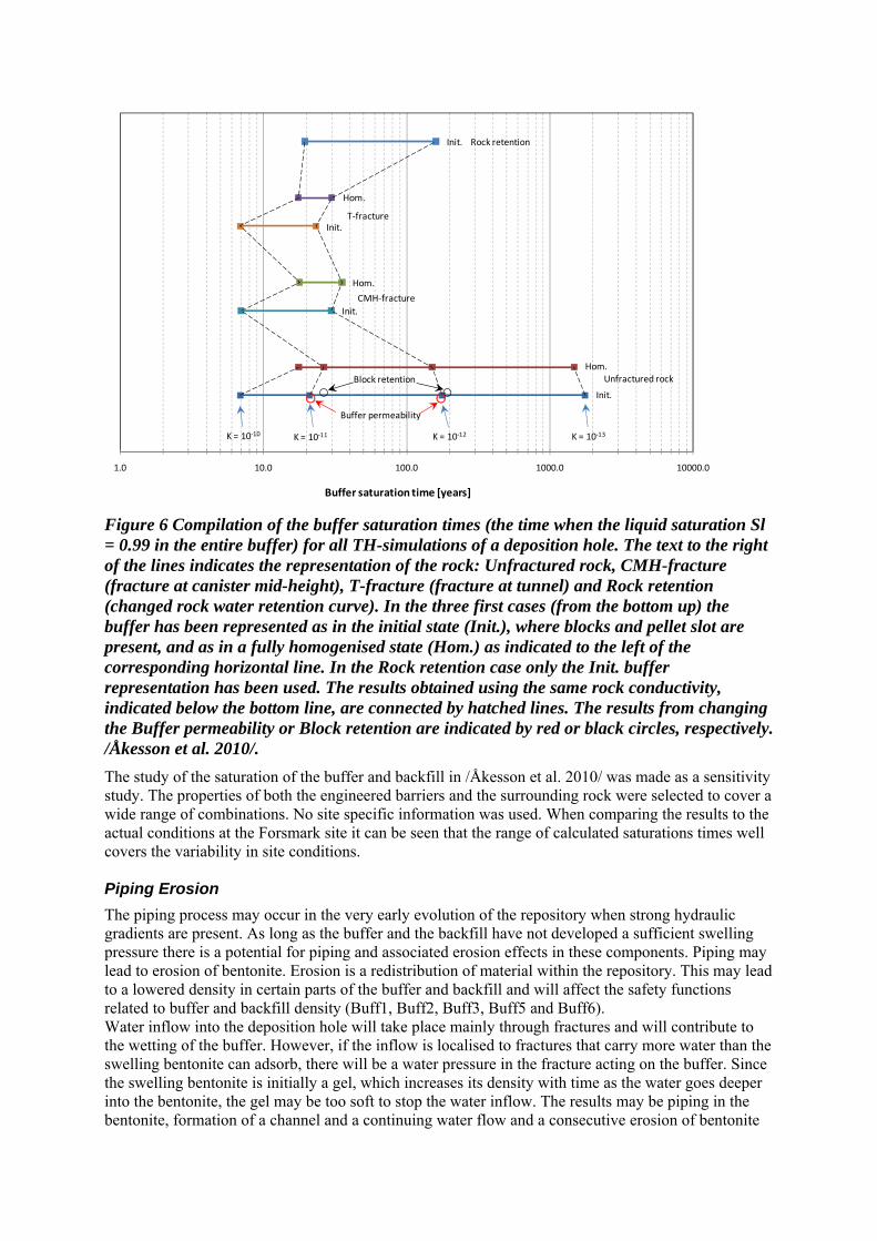
The buffer saturation times (the time where Sl ≥ 0.99 (liquid saturation) in the entire buffer), for all Thermo-Hydraulic (TH)-simulations of a deposition hole made in /Åkesson et al 2010a/, are shown in Figure 6. The horizontal lines represent the cases indicated to the right of the line where also the “mechanical assumption”, where Homogenised refers to an initially homogenised buffer material while Initial state considers the case with blocks and pellets, is indicated. The concept of using a homogenised and initial state model is to obtain two extreme solutions that are bounding the “true case” (in which mechanics, i.e. the homogenisation process, should be incorporated). Below the lower line (Init. Unfractured rock) the rock conductivity used is indicated. The hatched lines connect models with identical rock conductivities. Close to the lower line, the positions of the models where the buffer was altered are given (unfilled circles). A more detailed description of the cases can be found in /Åkesson et al. 2010/.
1.0 10.0 100.0 1000.0 10000.0
Buffer saturation time [years]
Unfractured rock
CMH‐fracture
T‐fracture
Rock retention
Hom.
Init.
Init.
K = 10‐11K = 10‐10 K = 10‐12 K = 10‐13
Block retention
Buffer permeability
Hom.
Init.
Hom.
Init.
Figure 6 Compilation of the buffer saturation times (the time when the liquid saturation Sl = 0.99 in the entire buffer) for all TH-simulations of a deposition hole. The text to the right of the lines indicates the representation of the rock: Unfractured rock, CMH-fracture (fracture at canister mid-height), T-fracture (fracture at tunnel) and Rock retention (changed rock water retention curve). In the three first cases (from the bottom up) the buffer has been represented as in the initial state (Init.), where blocks and pellet slot are present, and as in a fully homogenised state (Hom.) as indicated to the left of the corresponding horizontal line. In the Rock retention case only the Init. buffer representation has been used. The results obtained using the same rock conductivity, indicated below the bottom line, are connected by hatched lines. The results from changing the Buffer permeability or Block retention are indicated by red or black circles, respectively. /Åkesson et al. 2010/.
The study of the saturation of the buffer and backfill in /Åkesson et al. 2010/ was made as a sensitivity study. The properties of both the engineered barriers and the surrounding rock were selected to cover a wide range of combinations. No site specific information was used. When comparing the results to the actual conditions at the Forsmark site it can be seen that the range of calculated saturations times well covers the variability in site conditions. Piping Erosion
The piping process may occur in the very early evolution of the repository when strong hydraulic gradients are present. As long as the buffer and the backfill have not developed a sufficient swelling pressure there is a potential for piping and associated erosion effects in these components. Piping may lead to erosion of bentonite. Erosion is a redistribution of material within the repository. This may lead to a lowered density in certain parts of the buffer and backfill and will affect the safety functions related to buffer and backfill density (Buff1, Buff2, Buff3, Buff5 and Buff6). Water inflow into the deposition hole will take place mainly through fractures and will contribute to the wetting of the buffer. However, if the inflow is localised to fractures that carry more water than the swelling bentonite can adsorb, there will be a water pressure in the fracture acting on the buffer. Since the swelling bentonite is initially a gel, which increases its density with time as the water goes deeper into the bentonite, the gel may be too soft to stop the water inflow. The results may be piping in the bentonite, formation of a channel and a continuing water flow and a consecutive erosion of bentonite

particles. There will be a competition between the swelling rate of the bentonite and the flow and erosion rate of the buffer. The consequence of piping is always that there will be erosion of material that has been torn off from the pipes. That material is transported in the pipes out into either a stagnant part of the backfill where the eroded material may settle or out from the backfill into the open transport tunnel. A large number of erosion tests have been performed. Based on the tests an exponential erosion model described by the equation below has been suggested:
)( ws mm
where ms= accumulated mass of eroded bentonite (g)
mw= accumulated mass of eroding water (g)
= 0.02-0.2 = parameter defined by the level of erosion at a certain accumulated water flow. The range is valid for vertical erosion in deposition holes
α = 0.65 = parameter defined by the inclination of the straight line relation between ms and mw. For deposition holes where the inflow is at the limit value for acceptance in accordance with the design premises of 150 m3 the models yields an erosion of 4-41 kg of bentonite. Homogenisation after loss of bentonite mass
Swelling and mass distribution in the buffer is an important process to ensure that mass losses caused by piping and erosion do not have negative impacts on the safety functions (Buff1, Buff2, Buff3, Buff5 and Buff6). The swelling properties of bentonite make the buffer and backfill material swell and close open gaps or channels to form a more homogeneous medium. Homogenisation of buffer and backfill is crucial to fulfil the safety functions related buffer and backfill density (swelling pressure and hydraulic conductivity). Erosion caused by piping will not be prevented by the bentonite as long as water flow and high water pressure gradients persist in the deposition tunnel. This will be the case until the flow and gradients are limited by the tunnel plug. If the erosion is strong, large openings of missing bentonite may locally be formed. The swelling and sealing of bentonite cannot take place unhindered since there is a resistance to swelling caused by friction both internally in the bentonite and between the bentonite and the surrounding fixed walls represented by the rock surface. In order to investigate how well the buffer material seals the openings resulting from the mentioned processes a number of finite element calculations with the code Abaqus have been performed /Åkesson et al. 2010/. In the calculations a mass loss geometry in the form of a half torus shaped pipe around the deposition hole has been selected to maximise the mass loss around the canister. A more likely geometry would be a vertical half pipe going up towards the deposition tunnel. The results from the variations of the water supply show that the final swelling pressure varies very little as a function of the water supply. However, the time for saturation and sealing of a pipe with radius of 67 mm (61 kg) varies from 2.2 years for the case where the water is supplied from rock surface, the inside space and the backfill to 42 years when water is only supplied from the backfill. The final swelling pressure in the original hole (pipe) is around 1.2 MPa. Variations of the radius of the half torus also yielded very similar final swelling pressures, even though 240 kg of bentonite is lost when the radius is increased. Swelling and swelling pressure
Swelling and mass distribution in the buffer is also important after the saturation process is completed. The primary purpose of the buffer is to ensure that transport of species from the rock to the canister and from the canister to the rock is dominated by diffusion. The swelling pressure in the bentonite is expected to seal all gaps and ensure that there is tight contact between the rock and the buffer. It is, therefore, important that the swelling pressure is maintained. The safety function indicator criterion for ensuring tightness in the buffer is a swelling pressure of 1 MPa, safety function indicator Buff1b in Fehler! Verweisquelle konnte nicht gefunden werden.. A high swelling pressure is needed for

reducing microbial activity (Buff2). The required swelling pressure for preventing canister sinking is 0.2 MPa (Buff 5). On the other hand, the swelling pressure must not be higher than 15 MPa in order to limit the pressure on canister and rock (Buff6). In order to verify that the intended conditions after swelling will be reached, it is, necessary to assess more carefully the swelling process with focus on: buffer homogenisation,
buffer upward expansion,
movement of the canister in the deposition hole,
homogenisation after loss of bentonite mass.
Buffer homogenisation
The initial state of the buffer after placement is unsaturated bentonite blocks and rings with much higher density than the average density for the entire hole and one empty slot at the canister surface and a pellet filled slot with very low density at the rock surface. Due mainly to friction within the material, but also due to hysteresis effects, the swelling and homogenisation that comes with the wetting of the bentonite is not complete and there will remain density differences and swelling pressure differences in the buffer. The important geometrical components of the models are the initial open slot between the canister and the buffer blocks, the buffer blocks themselves and the pellet filled outer slot as shown in Figure 7. The key phenomena investigated with the Code_Bright, was the influence on the homogenisation and swelling pressure of slot width in a section between the canister and the rock and the wetting sequence. In the study, the slot width was varied from 3 to 9 cm with the other parameters kept constant. Figure 8 shows the final swelling pressure in the buffer components as a function of slot width.
open slot bentonite block pellet slot
canister
rock
0.525
0.5350.825
0.875
Figure 7 Model geometry and constituents /Åkesson et al. 2010/

0
2
4
6
8
10
12P
ress
ure
[M
Pa]
pellet slot 8.48 6.54 3.89
block 9.97 7.65 4.72
tot 9.91 7.55 4.57
w=3 cm w=5 cm w=9 cm
Figure 8 Averages of pressure for 3, 5 and 9 cm pellet slot /Åkesson et al. 2010/.
The finite element code Abaqus was used to model the homogenisation process in an entire deposition hole with identical initial conditions and boundary conditions with those in the CRT. The results shown in Figure 9 and Figure 10 give an expected final density and stress distribution in a deposition hole covered with a backfill that is compressed about 3 cm.

Figure 9 Final state of the buffer after full saturation and completed homogenisation. The distribution of the dry density and the vertical swelling is shown /Åkesson et al. 2010a/.

Figure 10. Final state of the buffer after full saturation and completed homogenisation. The distribution of radial and axial stress is shown /Åkesson et al. 2010a/.
The only remarkable observation is that there is no obvious density gradient (decrease in density and swelling pressure towards the backfill) in spite of there being an upwards swelling of 3 cm. Buffer upward expansion
One of the main design requirements of the backfill is to keep the buffer in place and prevent it from swelling upwards so that the buffer will not lose too much of its density. Some upwards swelling is expected since the backfill has a lower swelling pressure than the buffer and a certain degree of compressibility. At installation both the buffer and the backfill consist of bentonite blocks with very high density and different degrees of saturation and pellets filling all remaining slots between the blocks and the rock surface. Then water enters the deposition hole and the tunnel with wetting and swelling of the blocks together with wetting and compression of the pellet filling. The rate of these processes depends on the rate and location of water inflow and the actual evolution of the saturation and homogenisation of the buffer and backfill. The corresponding interaction between the buffer and backfill materials is

different in every deposition hole. The complicated nature calls for simplifications in order to be able to model the process with moderate effort. The extreme cases are to assume either completely saturated (wet) or completely un-wetted (dry) conditions, which yield four cases: 1. Wet buffer and wet backfill 2. Wet buffer and dry backfill 3. Dry buffer and dry backfill (uninteresting) 4. Dry buffer and wet backfill
Case 3 is obviously not interesting and is therefore not considered, but also case 4 is not of primary interest since there will be very little compression of the buffer blocks and rings. It was found that Case 2 had the largest impact on the final buffer density and /Åkesson et al. 2010/ did additional studies on the case with a wet buffer and a dry backfill. The objective was to carry out additional modelling of the dry case with some alternative geometries that were not considered in the former models and check how the final density distribution of the buffer in the deposition hole is affected by the swelling of the buffer and consequent compression of the backfill. Three calculations were done with different initial densities of the buffer and different slot heights at the roof. The results show that there will be a significant upwards swelling in the extreme case of a completely water saturated buffer material and a completely un-wetted backfill. The geometry modelled had a degree of block filling of about 76% and a pellets filled slot at the roof of 30 or 55 cm. The important results of the three calculations are summarised in Table 2.
Table 2 Summary of results for the cases with slot at the roof
Variable Model 1 Model 2 Model 3 Density at saturation 2,000 kg/m3 2,000 kg/m3 1,950 kg/m3 Pellets filled slot 30 cm 55 cm 55 cm Max buffer upwards swelling 96 mm 102 mm 68 mm Canister heave 4.8 mm 5.0 mm 3.2 mm Buffer density at top of canister 1,960 kg/m3 1,960 kg/m3 1,920 kg/m3 Average axial swelling pressure at top of canister
3.8 MPa 3.6 MPa 2.1 MPa
The modelled cases represent an extreme wetting situation and have a rather large pellets filled slot at the roof. Most important for the upwards swelling are the horizontal joints between the backfill blocks. The properties of those joints are not known and the stress-strain relation used is estimated. The results show that there is a loss in density of the buffer above the canister but the resulting lowest density at water saturation at the canister/buffer contact at the initial density 2,000 kg/m3 is 1,960 kg/m3. If the initial density is only 1,950 kg/m3, the corresponding final density will be 1,920 kg/m3, but the swelling pressure is still 2.1 MPa. The overall picture is that the swelling pressure of the buffer and the associated safety functions will be maintained during the expansion of the buffer into the backfill for all possible combinations of buffer and backfill conditions. Movement of the canister in the deposition hole
One of the safety functions for the buffer is that it should prevent the canister from sinking in the deposition hole since this would render the canister in direct contact with the rock thus short-circuiting the buffer. Canister settlement consists mainly of four different processes:
1. Consolidation/swelling caused by the canister weight 2. Volumetric creep caused by the canister weight 3. Deviatoric creep caused by the canister weight 4. Stress changes caused by upwards swelling of the buffer/backfill interface
a) Consolidation/swelling b) Volumetric creep c) Deviatoric creep

The fourth process can thus be divided into the same processes as the first three processes but the consolidation and creep is caused by the swelling pressure from the buffer on the backfill instead of the weight of the canister. The settlement of the canister has been modelled in /Åkesson et al. 2010/. The calculations include two stages, where the first stage models the swelling and consolidation that takes place in order for the buffer to reach force equilibrium. This stage takes place during the saturation phase and the subsequent consolidation/swelling phase. The second stage models the deviatoric creep in the buffer over 100,000 years. The base cases in the calculations correspond to the final average density at saturation of 2,000 kg/m3 with the expected swelling pressure 7 MPa in a buffer. In order to study the sensitivity of the system to loss in bentonite mass and swelling pressure seven additional calculations were done with reduced swelling pressure down to 80 kPa corresponding to a density at water saturation of about 1,500 kg/m3. The results of the calculations with fixed backfill boundary and the corresponding friction angle at retained initial swelling pressure are summarized in Table 3. The canister settlement shown in column 5 also includes the consolidation settlement, which takes into account that the compressibility increases when the swelling pressure decreases whereas a reduced friction angle with retained swelling pressure will not have an increased compressibility. The settlements at the presented friction angles have for this reason been recalculated as the sum of the settlement of the base case and the creep from respective creep calculation (column 7)
Table 3 Summary of results from the calculations with fixed buffer/backfill boundary /Åkesson et al 2010/.
Calculation
No
Density at saturation
m (kg/m3)
Swelling pressure
p (kPa)
Mises´ stress at failure
qf (kPa)
Canister settle-ment
(mm)
Friction angle at retained swelling pressure
(˚)1)
Canister settlement at
corresponding friction angle and retained
swelling pressure
(mm)2)3)
1 (base case)
2,010 7,000 2,238 0.35 8.8 0.35
2 1,950 3,500 1,312 0.67 5.2 0.47
3 1,890 1,750 770 1.26 3.1 0.67
4 1,840 875 451 2.42 1.8 1.04
5 1,780 438 265 4.63 1.1 1.67
6 1,720 219 155 8.89 0.63 2.78
7 1,690 (1,640)1)
160 122 12.0 0.50 3.51
8 1,620 (1,470)1)
80 72 22.5 0.29 5.54

1) For the actual values of void ratio and density at saturation since the void ratio, e>1.5 and
Equation 16
3
fqp
2) Derived from the consolidation in the base case (0.20 mm) + the creep from respective creep calculation
3)The total bottom buffer thickness is 500 mm
The conclusion is thus that the expected displacement of the canister in a deposition hole from consolidation and creep during 100,000 years is very small. Homogenisation after loss of bentonite mass
Homogenisation of buffer and backfill is crucial to fulfil the safety functions related to buffer and backfill density (swelling pressure and hydraulic conductivity). The swelling properties of bentonite make the buffer and backfill material swell and close open gaps or channels to form a more homogeneous buffer. These properties are important not only for homogenising the buffer and backfill after installation of the bentonite blocks but also for limiting the potential for the long term formation of openings in the buffer and backfill. Except for the natural slots that exist after installation, which are treated in the Buffer homogenisation section, such spaces may appear for several reasons, as summarised below.
1. The postulated case of missing bentonite rings.
2. Erosion before closure of the repository caused by water inflow into deposition holes and a deposition tunnel until the water flow and high water pressure gradients are stopped by temporary plugs. If the erosion is severe, large openings of missing bentonite may locally be formed.
3. Long term erosion of bentonite by water from fractures intersecting the deposition hole or the deposition tunnel mainly caused by bentonite dispersion and subsequent colloid transportation after fresh water intrusion.
The consequences of erosion before the closure have been discussed earlier. Case 1 is only postulated and Case 3 is only relevant for very long timeframes. Therefore, this process will not be discussed further in this document. Buffer chemical evolution
The processes: “Advective transport of species”, “Diffusive transport of species”, “Sorption (including ion-exchange), “Alterations of impurities” and “Aqueous speciation and reactions” are all parts of the geochemical evolution of the buffer. After deposition, the buffer is subjected to a thermal gradient due to the heat generation from the canister. At the same time there will be a hydraulic gradient caused by the suction in the unsaturated bentonite blocks and the hydrostatic pressure in the surrounding rock. After saturation and cooling of the near-field, the interaction of groundwater with the bentonite buffer may result in an evolving distribution of some aqueous species in the bentonite porewater, as well as the redistribution of accessory minerals and the cation exchanger. Three aspects must be considered regarding the geochemical evolution of the near field: 1. The effect of the thermal period; 2. The processes during the saturation of bentonite; 3. The interaction of the water-saturated bentonite with the local groundwater.
There are no buffer safety functions directly connected to this evolution, but an assessment needs to be made as to whether this evolution indirectly would violate the buffer safety functions. During the period of bentonite saturation (before 10, 100, 1,000 and 2,000 years, depending on the hydrological model) advection of solutes to the bentonite porewater is the main mechanism of

transport between the groundwater and the buffer. The effect of solute diffusion between the inflowing groundwater and the bentonite porewater is negligible in the cases with a high rate of water saturation (10 and 100 years). In the models with low rates of saturation (1,000 and 2,000 years), the effects of the diffusion on the calculated concentrations during the period of saturation are significant. When the bentonite buffer becomes fully saturated, diffusion is the exclusive mechanism of solute transport. During the thermal period of the repository, the initially unsaturated compacted bentonite will progressively saturate due to the hydraulic pressure of the surrounding rock (Figure 11). Although the main transport mechanism in the low permeability compacted bentonite is diffusion, advective transport will be more important during the saturation stage due to the capillary pressure that is established during this stage.
Heat flow
Spentnuclearfuel
Water flow and transport of solutes
Evaporation
Condensation
Wetting front
Copper tube
Bentonite buffer
Host rock
Figure 11 Sketch of a vertical cross section of the near-field of a KBS-3 repository showing the thermo-hydraulic and transport processes that are believed to occur during the saturation period of the bentonite buffer /Sena et al. 2010/.
The buffer material consists of montmorillonite and accessory minerals. In the repository environment these minerals may dissolve and sometimes re-precipitate depending on the prevailing conditions. /Sena et al. 2010/ has calculated the redistribution of accessory minerals during the early repository evolution when a thermal gradient is present and the details about the processes and mechanisms in the modelling can be found in the reference. In the calculations the following was tested:
1. The saturation time 2. The flow rate in a fracture intersecting the deposition hole.
Under a higher flow rate regime within the fracture, the effect of the diffusion of solutes from the bentonite porewater to the granite or vice versa on the chemical conditions of the granite around the deposition hole will be rapidly buffered by the supply of unaffected granitic groundwater. Under these conditions, the geochemical changes induced by the chemical reactions taking place in the buffer will be limited to the buffer itself since any influence of these over the chemical conditions of the granite will be rapidly flushed due to granitic groundwater renewal On the other hand, if the advective flow in the fracture is very low, diffusion will prevail and therefore, the chemical and diffusive processes occurring in the buffer will influence the chemical conditions of the fracture around the deposition hole. In the calculations these parameters have been considered independently. However, a high flow rate would affect the saturation time. Therefore, no combinations of high flow and long saturation have been studied. Ca-sulphates are originally present in the MX-80 bentonite mineralogy. At the beginning of the thermal period, anhydrite precipitates in the bentonite pores due to the increase of temperature, except close to the outer boundary of the buffer where the granitic groundwater (which is unsaturated with respect to this mineral) flows into the buffer. The dissolution of the primary anhydrite is more efficient for a situation when the saturation is rapid (10 and 100 years in Figure 12).

0.0
0.2
0.4
0.6
0.8
1.0
0.50 0.55 0.60 0.65 0.70 0.75 0.80 0.85
An
hyd
rite
(wt%
)
Distance (m)
0 yr
10 yr
100 yr
1,000 yr
3,000 yr
10,000 yr
Saturation time 10 years
0.0
0.2
0.4
0.6
0.8
1.0
0.50 0.55 0.60 0.65 0.70 0.75 0.80 0.85
An
hyd
rite
(wt%
)
Distance (m)
Saturation time 100 years
0.0
0.2
0.4
0.6
0.8
1.0
0.50 0.55 0.60 0.65 0.70 0.75 0.80 0.85
An
hyd
rite
(w
t%)
Distance (m)
Saturation time 2,000 years
0.0
0.2
0.4
0.6
0.8
1.0
0.50 0.55 0.60 0.65 0.70 0.75 0.80 0.85
An
hyd
rite
(w
t%)
Distance (m)
Saturation time 1,000 years
Figure 12. Calculated evolution of the amount of anhydrite in the MX-80 bentonite buffer as a function of buffer saturation time /Sena et al. 2010/.
SiO2(am) is also a primary mineral of the MX-80 bentonite. The primary SiO2(am) in the bentonite is preferentially dissolved close to the inner surface of the buffer (left side in Figure 13). In the case with a relatively fast saturation (10 years), a small amount of SiO2(am) is also dissolved during the saturation period, close to the contact with the granite. Until 10 years, the SiO2(aq) concentration progressively increases, both in the bentonite and in the granite due to the solute supply by SiO2(am) dissolution close to the hot boundary of the system. After 10 years the aqueous SiO2 concentration decreases due to dilution provided by the inflow of the granitic groundwater, which is depleted in SiO2(aq) compared to the initial bentonite porewater.

2.75
2.80
2.85
2.90
2.95
0.50 0.55 0.60 0.65 0.70 0.75 0.80 0.85
SiO
2 (w
t%)
0 yr10 yr100 yr1000 yr10000 yrSaturation time: 2000 years
0.E+00
1.E-03
2.E-03
3.E-03
4.E-03
5.E-03
0.5 1.0 1.5 2.0 2.5 3.0 3.5
Distance (m)
[SiO
2 (a
q)]
(m
ol/k
g w
)
GraniteBent.
Figure 13. Calculated evolution of the amount of SiO2 in the modelled domain of MX-80 bentonite, for a saturation time of the bentonite of 10 years /Sena et al. 2010/.
In general, the calculated evolution of the composition in the montmorillonite exchanger in the MX-80 bentonite indicates that the concentration of sodium decreases with time in favour of more calcium adsorbed. The concentration of potassium and magnesium also decreases in the montmorillonite exchanger. Within the same case of advective flow in the fracture intersecting the deposition hole, the calculated evolution of the composition of the exchanger is very similar for the different cases of bentonite saturation. As a result of the numerical simulations in /Sena et al. 2010/, it can be concluded that the main mechanisms controlling the mineralogical changes of the bentonite during the thermal period are related to: the dependence of the mineral solubilities on the evolution of the temperature in the near-field, the solute transport and mass transfer between the groundwater flowing along the fracture and
the bentonite porewater.
The evolution of the concentrations obtained for the bentonite porewater is a result of mixing with the local groundwater during the period of bentonite water saturation, whereas thereafter, diffusion of solutes is the dominant mechanism. The distribution of the concentration of solutes in the granitic groundwater is a consequence of the ratio between: the diffusion rate through the granite-bentonite interface, the fluid flow rate along the fracture in contact with the deposition hole.
In this way, the results obtained considering two regimes of groundwater flow rates along the fracture intersecting the deposition hole are substantially different.

Effects of salinity
The process “Osmosis” basically describes how the hydromechanical properties of the buffer are affected by the ionic strength of the surrounding groundwater. The salinity of the groundwater influences the vapour pressure relation and thereby the water saturation process. However, for the groundwater at the Forsmark site the effect is negligible. Montmorillonite transformation
The advantageous physical properties of the buffer, e.g. swelling pressure and low hydraulic conductivity, (safety functions: Buff1, Buff2 and Buff5) are determined by the ability for water uptake between the montmorillonite mineral layers (swelling) in the bentonite. However, montmorillonite can transform into other naturally occurring minerals of the same principal atomic structure but with less or no ability to swell in contact with groundwater. The transformation processes usually involve several basic mechanisms. At the expected physico-chemical conditions in a repository, the following possible mechanisms are identified:
congruent dissolution, reduction/oxidation of iron in the mineral structure, atomic substitutions in the mineral structure, octahedral layer charge elimination by small cations, replacement of charge compensating cations in the interlayer.
Transformation from smectite (montmorillonite) to illite, which is the most common alteration observed in natural sediments, is well documented in different geological formations, and has been reproduced under laboratory conditions. The main mineralogical differences being that the illites have approximately one unit charge higher tetrahedral charge, and potassium as the main charge compensating cation. Thus, potassium is a must for the montmorillonite to turn into illite. Simplified, the total illitization reaction may be expressed: Ca2+/Na+-montmorillonite + K+ + (Al3+) → Illite + Silica + Ca2+/Na+ High content of smectite is commonly found in old formations exposed to repository temperatures. For example, /Velde and Vasseur 1992/ studied the time-temperature space of illitization in seven deep wells in four sedimentary basins in the US, Japan and France. In all wells there was a typical reduction of smectite content with depth, which represents increase in both age and temperature (Figure 14).
Figure 14. Smectite content versus depth in smectite-illite mixed layer material in two sediments representing relatively fast burial rate (left) and slow burial rate (right). T.G. indicates the present temperature gradient and B.R. indicates the burial rate. Redrawn from /Velde and Vasseur 1992/.
The prerequisites for a transformation are obviously present in the sediments and time and temperature are the governing parameters. A decrease to around 60% smectite was observed in the Californian

Norwal formation after 4.5 million years at a depth of 5 km, representing a final temperature increase of over 100°C. The same transformation took around 60 million years at a depth of 2 km and a temperature increase of around 70°C in the Texan Peelan sediments. The reaction rate at these repository relevant temperatures is consequently very slow in relation to the timescale of a repository. The silica solubility increases significantly at pH above 9. The tetrahedral silica in the montmorillonite consequently equilibrates at higher concentrations at pH over 9. Diffusive removal of silica or precipitation of new silica minerals thereby lead to a faster increase of the tetrahedral layer charge compared to near neutral conditions. The corresponding increase in concentration of charge compensating cations leads to a change in the interaction with water and thereby to a change in sealing properties. The layer charge may reach the critical value for collapse, which results in total loss of expandability and in principle, to the same consequences as for illitization. At pH 11 the total silica concentration is calculated to be approximately 16 times larger than at neutral pH conditions, and at pH 12.4, representing matured Portland cement, the theoretical increase in total silica solubility is more than 3 orders of magnitude higher than at near neutral conditions. The effect of the alkaline plumes is especially strong for young cement waters and for high temperatures, In the KBS-3 concept any contact between cement pore water and bentonite will occur at the contact with the bottom plate, plug and fracture grouting where the temperature is relatively low and the pH is restricted to < 11. The bentonite components should therefore be much more stable. The montmorillonite transformation in a KBS-3 repository is assumed to be small based on the following observations and arguments: 1. The timescale for significant montmorillonite transformation at repository temperatures in
natural sediments is orders of magnitude larger than the period of elevated temperature in a KBS-3 repository /e.g Velde and Vasseur 1992/
2. The bentonite material is close to mineralogical equilibrium to start with
3. Transformation is limited by transport restrictions.
4. All published kinetic models, based both on natural analogues and laboratory experiments indicate that the transformation rate is very low at repository conditions
Based on this reasoning two safety function indicator criteria have been defined (see also chapter 8). As long as the maximum temperature is below 100°C and the pH of the water in the rock is below 11 the montmorillonite in the buffer is assumed to stable for the timescale for assessment. Cementation
The term “cementation” has often been used in a broad sense to describe processes, which lead to specific changes in rheology and swelling properties of the buffer material. A number of quite different chemical/mineralogical and mechanical underlying processes could conceivably cause such cementation effects. The above sections addressing the underlying and related processes, i.e. montmorillonite stability, ion exchange, accessory minerals alteration, diffusive transport etc. are consequently very relevant to the cementation process. There are two main concerns about the effects of cementation on the bentonite buffer; one is an increase in hydraulic conductivity, and the other is an increase of shear strength. As described earlier in this section there is no reason to believe that there would be mineralogical changes in the buffer that would lead to substantial changes of the mechanical or hydraulic properties over the assessment timescale. The redistribution of soluble accessory minerals calculated in the previous section is rather limited and is not expected to have a significant impact on the buffer properties. However, there are experimental results that show that the mechanical properties of bentonite can be altered if the material is exposed to an elevated temperature in a saturated state /Dueck 2010/. This is observed both in field experiments over a number of years as well as in 24-hour laboratory experiments. Figure 15 shows the influence of temperature on the stress-strain behaviour for the two reference bentonites for a saturated density of about 2,000 kg/m3. A tendency towards increasing deviatoric stress at failure with increasing temperature is seen for both MX-80 and Ibeco RWC (Deponit CA-N).

However, the influence of temperature is in the same range as the difference between the two bentonites. The strain at failure is approximately the same for MX-80 and Ibeco RWC (Deponit CA-N) at the same density for any particular temperature.
0
1000
2000
3000
4000
5000
6000
0 5 10 15 20 25
q (k
Pa
)
strain (%)
F123 20˚C 2000
C108 150˚C 2000
C111 150˚C 2000
F120 200˚C 1980
F121 200˚C 2030
0
1000
2000
3000
4000
5000
6000
0 5 10 15 20 25
q (k
Pa)
strain (%)
E114 20˚C 2000
E117 150˚C 2010
Figure 15. Influence of temperature on the stress-strain behaviour of MX-80 (left) and Ibeco RWC (right) with a density about 2,000 kg/m3 /Dueck 2010/.
Important observations from /Dueck 2010/ are that the influence of temperature on the stress/ strain behaviour of bentonite can be seen after only a few hours of exposure and that milling and re-compaction after heating restored the original failure behaviour. It is evident that an increased temperature will have an effect on the mechanical properties of the bentonite. The reason behind this is still unknown. The effect is not very pronounced even at 150 degrees and does not seem to progress with time. However, this effect does have to be considered in the evaluation of shear load on the canister.
3.5 Identified uncertainties
3.5.1 Thermal evolution of the near field
For the thermal evolution during the initial temperate period there is an adequate margin to the peak temperature criterion for the buffer, even when the spatial variability of the rock thermal properties is taken into account and with other data essential for computing the result chosen pessimistically. However, the thermal evolution is input to other assessments of the reference evolution. Only a representative thermal evolution without uncertainty is propagated for use in these assessments since the uncertainty in the thermal evolution is sufficiently small that it would not impact these other parts of the assessment.
It is possible to envisage deposition sequences, e.g. when a canister is deposited centrally in a panel where nearby positions were deposited several years before, where the resulting temperature in the buffer would exceed the maximum allowed. Such situations will, however, always be avoided, but this observation highlights the need for careful thermal management of the disposal sequence. This needs to be further considered in providing feedback to current design premises.
3.5.2 Saturation of buffer
The saturation times for both backfill and buffer range from a few tens of years to several thousand years. Examples from across this entire range are likely to arise at Forsmark, since rock properties (matrix hydraulic conductivity and presence and characteristics of fractures) are the primary controls, with backfill and buffer properties only a secondary consideration.
3.5.3 Piping Erosion
Piping and subsequent water flow from a fracture into a deposition hole and further out into the deposition tunnel cannot be excluded if the inflow rate is higher than the rate of water absorption of the buffer material, since the pellet filling and the bentonite blocks cannot stop the water inflow until the deposition holes and the tunnel are water filled and the hydraulic gradient occurs over the end plug. Erosion tests have shown that the dry mass of eroded bentonite can be modelled as a function of the total volume of inflowing water according to the model discussed in this section, which yields a loss of 41 kg of dry bentonite mass if the inflow requirements on the deposition holes are fulfilled. The model is purely empirical and it is difficult to theoretically derive a model.
3.5.4 Homogenisation after loss of bentonite mass
The analysis of homogenisation processes occurring in the buffer after erosion yielding a half torus-shaped pipe indicates a strong decrease in density and swelling pressure in the analysed volume due to the friction in the bentonite. However, the swelling pressure after complete homogenisation is above 1MPa for the analysed cases with torus radius varying from 3.4 cm to 13.4 cm. The influence of the radius seems to be insignificant due to the long distance to the bentonite boundaries. For the cases when the piping occurs as a half torus (or half pipe) the conclusion is thus that more 100 kg of dry bentonite may be lost from one deposition hole due to erosion without violating the safety function of the buffer. However, the uncertainty in the assessment of the eroded volume will be considered when revising the design premises in order to determine the acceptable inflow to deposition holes.
3.5.5 Swelling and swelling pressure
If the buffer and backfill is installed as envisaged by the reference design, the buffer density and swelling pressure will homogenise to a situation where the relevant safety functions will be upheld. Modelling of the large-scale tests and comparison with measurements confirm that the material model of unsaturated bentonite blocks and the calculation technique used are relevant for modelling the homogenisation process. The uncertainties are mainly the material models, which are very complicated, and the parameter values. Although they have been verified for the one-dimensional case of swelling and homogenisation of the bentonite rings and pellets between the canister and the rock, the two-dimensional case involves more degrees of freedom for the variables and more interactions like the friction between the bentonite and the rock or canister. The overall picture is that the swelling pressure of the buffer and the associated safety functions will be maintained during the expansion of the buffer into the backfill for all possible combinations of buffer and backfill conditions. However, in the analysis the buffer is modelled as completely water saturated and homogenised from start, which may affect the results such that the modelled density gradient between the canister and the backfill probably is larger than if a heterogeneous unsaturated buffer was modelled. The mechanical behaviour of the horizontal contacts between the backfill blocks has not been measured. The effect of local crushing of the blocks that may occur close to the floor is not included in the model, but this is not expected to yield any problems. Another uncertainty relates to how the blocks are piled. It is assumed that the blocks are not overlapping each other, which means that there will be no lateral spreading of the pressure. The swelling is expected to be smaller if the blocks are piled with overlaps like masonry. The safety function for canister settlement in the deposition hole will not be violated as long as there is a reasonable amount of buffer left in the deposition hole.
3.5.6 Buffer chemical evolution
The geochemical changes in the buffer during the period of saturation and thermal gradient are small and are not considered to have any significant impact on the long-term performance.

In the reference evolution, both the pH and the temperature in the buffer are assumed to be within the given limits and mineral alteration is not expected to proceed to a level where it will affect the properties of the buffer. The salinity of the groundwater influences the vapour pressure relation and thereby the water saturation process, but for the groundwater at the Forsmark site the effect is negligible. An increased temperature will have an effect on the mechanical properties of the bentonite, but the effect is not very pronounced even at 150 degrees and does not seem to progress with time.
3.5.7 Summary of issues
Mass loss due to piping and erosion in the very early evolution Swelling and homogenisation of components with different density and sealing after losses of
mass The importance of friction within the bentonite and between bentonite and other materials –
also in the unsaturated state Effects of temperature on the mechanical properties

4 France To fulfill its obligations as stipulated in the 1991 French Waste Act, Andra submitted the Dossier 2005 to French Government in 2005. This Dossier reports on Andra’s feasibility study pertaining to deep geological disposal of high level and long lived radioactive waste. Andra has based its approach of safety and reversibility, in the Dossier 2005, on the close integration of scientific knowledge – including site characterization -, engineering studies and safety assessments. This has lead to the utilization and development of specific tools, such as FA (Functional Analysis) PARS (phenomenological analysis of repository situations) and AQS (qualitative and quantitative safety analysis). The waste inventory to be disposed constitutes basic input data of the Dossier 2005. The underlying design options and the feasibility assessment are based upon knowledge of such an inventory. Quantity, type, and characteristics of current and future waste packages, as well as their long-term behavior in a repository environment and eventual radionuclide release are at the core of this knowledge. In the Dossier 2005, three main types of wastes were treated, without prejudging at this step, the reprocessing scenarios which would or should be considered at least: - Intermediate level long lived waste (ILW-LL or MAVL-type waste) - high level waste (HLW) :
vitrified wastes (or HA-type waste) spent fuels (CU-type waste).
The French planning Act of 28 June 2006 prescribes that a deep geological repository in clay formation is the reference system for intermediate and long lived waste management, and defines as objective for Andra to submit a licensing application in 2014-2015. Spent fuel wastes are not considered as wastes anymore. Nevertheless, particular spent fuels, those from naval propulsion and research reactors, are still taken into account. As Clay buffer material only concerns spent fuel disposal cells, this chapter essentially deals with studies on spent fuel which have been carried out for the French Dossier 2005 /Andra 2005a/, /Andra 2005b/, /Andra 2005c/.
4.1 Repository concept
4.1.1 The Meuse / Haute-Marne site and the Callovo-Oxfordian clay layer
The Meuse / Haute-Marne center is defined as the authorized perimeter for the construction of the underground research laboratory. It is located in Eastern France, on the boundary between the Meuse and Haute-Marne departments (see Figure 1). Geologically, the Meuse / Haute-Marne center is part of the eastern region of the Paris Basin. In this region, the Paris Basin is composed of alternating sedimentary layers (predominantly argillaceous) and limestone layers, deposited in a stable marine environment during the Jurassic, between 165 and 135 million years ago. These layers have a simple and regular geometric structure, slightly sloping towards the northwest (1.5 to 2 degrees) in accordance with the general structure of the Paris Basin (bowl-shaped structured centered in the Paris area). Within the sedimentary sequence, the Callovo-Oxfordian clay layer has been selected for the repository emplacement. It is surrounded by two geological formations (underlying Dogger and overlying carbonated Oxfordian) containing aquifers sedimentary horizons with low permeability and slow runoffs (approximately one kilometer per hundred thousand years for the Darcy water velocity). The structural framework is stable, with natural mechanical stresses oriented in a stable manner for the past 20 million years. The center is located apart from large regional faults such as the Marne fault towards the southwest. The Callovo-Oxfordian layer is an argillaceous layer at least 130 meters thick, laterally homogeneous, with low porosity (15 %) and low permeability, consisting of argillaceous mineral phases (smectites,

illites and illite/smectite inter-layers) representing up to 60 % of its mass, as well as silts (fine quartzes) and carbonates. The 3D seismic data produced by Andra shows no faults with a vertical throw exceeding 2 meters within the layer. Directional boreholes confirm the absence of secondary (sub seismic) faults. Moreover, only a few micro fissures, stable and not affecting water flow, have been observed in over 4 km of core samples, and some of them are sealed with sulphates (celestine), which is indicative of a precocious formation during the compaction of deposits. Finally, the argillites have mechanical properties favoring the feasibility of underground engineered structures at the depth of the Callovo-Oxfordian layer in the transposition zone (simple compression resistance > 21 MPa) and also significant thermal properties (thermal conductivity of between 1.2 and 2,7 W.m-1.K-1, depending on the stratigraphy). Based on the position of the underground research laboratory, Andra defines a transposition zone within which the Callovo-Oxfordian layer has physical and chemical properties similar to those observed at the laboratory. Its surface area is approximately 250 km². The depth of the Callovo- Oxfordian roof varies from 420 m at the underground research laboratory to over 600 m along the dip direction, and the thickness of the layer varies from 130 m at the laboratory to 160 m towards the north. The repository will be located within the transposition zone.
4.1.2 Overall design of the repository
The repository design is intended to meet the safety and reversibility objectives. Simplification and control of the repository's phenomenological evolution are principles adopted to favor/ensure repository safety and reversibility. Various design measures contribute to achieving this goal. Repository location in the middle of the Callovo-Oxfordian layer
In order to take into account the nearly horizontal geological structure of the Callovo-Oxfordian layer and preserve a sufficient minimum distance between the repository and the surrounding formations, the repository is constructed on a single plane within the layer (at least 60 m from the top of the Callovo-Oxfordian layer according to its thickness within the transposition zone). At the location of the Meuse / Haute-Marne underground research laboratory, the Callovo-Oxfordian layer has a thickness of approximately 135 meters. For the Dossier 2005, conventionally the repository was therefore positioned in the middle of the Callovo-Oxfordian layer. This corresponds to a distance of 65 meters between the roof and wall of the layer and the mid-plane of the repository, thus ensuring a clearance of 60 meters of argillites between the repository (average thickness: 10 meters) and the surrounding carbonated Oxfordian and Dogger formations. The thickness of the Callovo-Oxfordian layer increases from the underground research laboratory over the rest of the transposition zone; for any other position of the repository within the transposition zone, the distance of 65 meters between the roof of the layer and the mid-plane of the repository was adopted by convention. Compartmented and modular repository architecture
Compartmented and modular repository architecture with distinct and separate reference package repository zones for each type waste (and distinct and separate disposal modules within each repository zone). The objective here is to limit or prevent any phenomenological interaction between repository zones and between disposal modules within the same zone, thereby effectively minimizing the complexity of their phenomenological evolutions. The repository then behaves as a sum of elementary repositories that are nearly independent with regard to phenomenological evolution. Orientation of the engineered structures to limit mechanical perturbations
In order to limit the mechanical stresses exerted by the repository structures on the argillites in the near-field (particularly to prevent the formation of a excavated disturbed zone in the near field with permeability zone larger than this of undisturbed argillites, which could increase water fluxes within the repository or significantly decrease the migration times of the radionuclide released by the

packages), the disposal cells and the drifts accommodating the repository's hydraulic closure seals are oriented in the direction of the major mechanical stress. Compactness of the repository to limit mechanical perturbations
Empty spaces and residual gaps within the repository after its closure are generally minimized to ensure a compactness limiting mechanical deformations of the repository and its geological environment. This is the purpose of the drift backfill (as dense as possible). Limiting the increase in temperature associated with the heat release from waste packages
HA waste and spent fuels are characterized by significant heat release. At this stage of the studies, in order to remain within a temperature domain that is currently well understood in terms of (i) evolution of the materials, (ii) knowledge and modeling of the phenomena involved and (iii) limited or negligible impact on the properties of the repository components and Callovo-Oxfordian layer, a maximum temperature of 90 °C is defined for HA-waste in contact with argillites and for spent fuels in contact with the clay buffer (see below).
4.1.3 Spent fuel disposal cell
Disposal cells for spent fuel are horizontal tunnels, some 45 meters long, in which the disposal packages are placed in rows. In the case of PWR fuels releasing considerable heat (1000 to 1500 watts per package after pre-disposal storage of 60 to 90 years), the disposal packages are spaced apart with spacers and each tunnel contains three of four packages. The number of assemblies in each package depends on the type of spent fuel and, in particular, the heat released. For PWR fuels, the packages studied contain one (in the case of MOX – package type CU2) or four assemblies (in the case of UOX – package type CU1). Moreover, the disposal package design ensures that the risk of criticality is controlled over the various time scales. For the design of spent PWR fuel disposal cells, the insertion of a swelling clay buffer (engineered barrier) between the packages and the geological formation has been adopted. The aim is to safeguard against uncertainties in the thermo-mechanical behavior of the cell, caused by a relatively slow decrease in the heat released from the spent fuel. Where water saturates the cell, this option enables a continuous, low-permeability medium to be formed around the packages by exploiting the capability of certain clays to swell considerably in the presence of water, and accept a high deformation rate. This barrier will limit, locally, the transport of dissolved species and thereby favor the control the physical and chemical environment of the fuel. It makes it possible to manage the uncertainties existing at this stage regarding the thermo-hydro-mechanical evolution of the argillites located in proximity during the thermal phase. The excavated diameter of the disposal cell corresponding to this configuration is around 3 meters. The engineered swelling clay barrier is provided with an axial internal sleeve to enable the introduction and possible future withdrawal of the packages.

Figure 16 Scheme of spent fuel (UOX or MOX) disposal cell in operation
The spent fuel disposal cells are closed by the emplacement of a swelling clay plug held by a concrete retaining plug.
Figure 17 Scheme of sealed spent fuel disposal cell
The cell, as designed at this stage of the studies, is a tunnel closed at one end, around 3.3 m in diameter in the case of the CU1 cell and around 2.6 m in diameter for the CU2 cell. In the usable part destined to receive the packages, the cell consists of three components: a steel lining, a swelling clay-based engineered barrier with a radial thickness of 800 mm, and a permanent metal sleeve (maintained after closing). The sleeve facilitates the positioning or withdrawal of packages. The head of the cell is designed to receive a seal. The latter consists of a clay plug and a concrete retaining plug. The peripheral parts of the retaining plug (clay and concrete) are positioned after the swelling clay buffer, before the packages. The central space allows the packages to pass and to this end receives a temporary sleeve, removed in order to close the cell. Main operating steps of the disposal cell are: To fit the clay buffer and the sleeve The clay buffer described above is formed by complete rings in a single piece. The external diameter of the rings is approximately 2 meters and their thickness (along the cell axis) is 0.5 m. These dimensions are due to manufacturing constraints. Each ring pre-fabricated in this way will weigh approximately 5 tonnes. A high-capacity uni-axial press (for example: 30 000 tonnes) makes it possible to achieve the pressures in excess of 50 MPa required to obtain dry densities of around 1.9. To insert pre-assembled buffer rings In order simplify the positioning operations, the rings can be assembled in the workshop in groups of four. There are various possible techniques for fitting these rings into the cell. For reasons of size and the availability of experience feedback, the air cushion technique appears to be particularly suitable.

The pre-assembled rings are placed on a cradle fitted with air cushions. After the air cushions have been inflated, a trolley rolling on guide rails pushes the cradle to the required position in the cell. The air cushions are then deflated. The rings then sit on the rails, thus freeing the cradle. The carrying capacity of a 380 mm diameter air cushion is around 2 500 kg. Each cushion is inflated to 0.3 MPa and slightly raises the ring to be moved by lifting it. The procedure for putting heavy loads with large diameters in place is the subject of technological testing in the framework of the ESDRED project. To close the disposal cell The spent fuel disposal cell closing process begins as for that of the type HA disposal cell, with the fitting the metal radiological protection plug. Once the choice has been made, there follows the fitting of the swelling clay core, in addition to the rings already installed. There are at least two possible processes:
one consists of inserting pre-fabricated cylinders in the central space, probably at the same time as the temporary sleeve is withdrawn; this process, however, leads to the creation of an initial round space between the prefabricated cylinders and the rings already in place (thickness of the temporary sleeve increased by the handling clearance), a space which will in time close up as the clay swells;
another possible process would consist of compacting clay pellets or powder in-situ; it would be done in the same way as the solution described for the type C disposal cell.
At this stage, the prefabricated component solution appeared to be the simplest. The next phase consists of producing the retaining plug. Unlike for the type C disposal cell, part of the retaining plug is already in place before closing the cell (prefabricated concrete rings). Closing therefore consists of pouring an additional concrete plug in the central space and, if necessary, injecting the concrete/concrete and concrete/lining contacts.
4.2 Safety assessment methodology
The feasibility assessment builds upon a number of key elements: - Basic input: the inventory model of the waste and the geological site; - Safety functions and requirement management; - Technical solutions based on industrial experience; - Reversible management and monitoring; - Phenomenological Analysis of Repository Situations (PARS) and detailed, coupled process
modeling; - Qualitative Safety Assessment (AQS); - Quantitative Safety Assessment (AQS). Although the following sections may suggest a linear progression from basic input data to designing a “solution” and assessing its safety, the process thus summarized is in fact highly iterative, with repeated feedback exchanged between the various processes. In addition to the routine feedback common to parallel engineering, three main iteration loops have been identified since 1991, each corresponding to a major milestone of the program: License application for construction and operation of the underground research laboratory (in 1996), submission of the Dossier 2001 (in 2001), and the submission of the Dossier 2005 (in 2005).

Acquisition of knowledge Architecture and design
Science and safety studies
Feedback concerning
Comprehension of the systemModelling and simulation
Research priorities Design orientations
Newiteration
• uncertainties• design• robustness• feasibility
Newiteration
Acquisition of knowledge Architecture and design
Science and safety studies
Feedback concerning
Comprehension of the systemModelling and simulation
Research priorities Design orientations
NewiterationNewiteration
• uncertainties• design• robustness• feasibility
NewiterationNewiteration
Figure 18 An iterative design approach
4.2.1 Basic Input Data
The waste inventory to be disposed of constitutes basic input data for the feasibility study of HLW disposal and includes future, but already identified waste that has yet to be produced by the current French nuclear power plant fleet. The underlying design options and the feasibility assessment are based upon knowledge of such an inventory. Quantity, type, and characteristics of current and future waste packages, as well as their long-term behavior in a repository environment and eventual radionuclide release are at the core of this knowledge. To this end, Andra has compiled an inventory of the waste - the Dimensioning Inventory Model (MID), as well as the reference document on waste package behavior. It was developed in collaboration with the waste producers (EDF, AREVA, CEA) and takes into account several possible future spent fuel reprocessing scenarios. It ensures that bounding values pertaining to disposed waste are used in the feasibility assessment. The geological site constitutes another basic input to the study. A decade of research has provided Andra with sufficient data to conclude that the Callovo-Oxfordian formation at the Meuse / Haute-Marne site has properties that are one of the pillars of the safety case. Moreover, the site properties respect other key selection criteria of the Basic Safety Rule, such as absence of notable natural resources. The Callovo-Oxfordian host rock layer is a stiff, argillaceous rock formation, 155 million years old and located at a depth between approximately 400 m and 600 m, where it is unaffected by future climatic changes or erosion. Its very low permeability, homogeneity over a large area and absence of faults result in negligible water circulation. Its significant contribution to the safety case is related to its very low permeability and good sorption properties, as well as other favorable chemical properties, providing for a strong buffer effect. Laboratory and in situ experiments all yield permeability values in the range of 10-12 to 10-14 m/s, with most data points ranging from 5×10-13 to 5×10-14 m/s. In situ and laboratory diffusion experiments on samples taken at different depths in the Callovo-Oxfordian layer all point to diffusion coefficient reference values of 5×10-12 m2/s for anions (in particular for iodine and chloride) and of 2.5×10⁻¹¹ m2/s for tritiated water. Furthermore, a diffusive transfer model across the Callovo-Oxfordian layer was shown to provide a satisfactory fit of chloride concentration distributions. The host rock confinement properties are preserved over the long term: its deformation is small, it responds well to perturbations resulting from excavation and from the thermal and chemical impact of construction materials and of emplaced waste. It benefits from a stable geological environment and its surrounding formations also show low permeability and slow water circulation. According to Andra’s

investigations, these favorable properties may be found throughout a 200 km2 transposition zone to the North and West of the URL.
4.2.2 Functional Analysis and System Requirements
Andra wanted to make the maximum use of the notion of “safety functions” that is gradually being recommended at the international level as a complement to the multi-barrier approach. In many ways, the “multi-function” approach is a generalization of the “multi-barrier” concept. It allows safety to rest on multiple functions performed by various components of the disposal system. This approach acknowledges the fact that the components of a repository may not act as traditional “barriers” once the repository is closed, as total containment may not be guaranteed in the long run. Safety functions give access to a finer definition of the role of each component. It may allow to identify features that are important for the global safety of the repository, even though they may not relate to a containment capacity. For example, the backfill of the repository has no containment function, and therefore is not a “barrier” in the traditional sense of the word. However, its mechanical function with relation to the prevention of EDZ over-extension may become important for safety. By identifying the functions that are to be performed if one wants to guaranty the safety of the repository, one makes a natural link between safety objectives on the one hand, the features and processes that are critical as regards safety functions, and the engineering options that may favor safety functions. Therefore, the clear identification of safety functions, and a shared understanding of this notion among different teams within Andra, are the main tools to provide a natural link between engineering, phenomenological understanding, and safety. The fundamental safety function: - To protect man and the environment from the dissemination of radionuclide, led to the
definition of three high-level safety functions, that are at the core of the long-term safety assessment:
- To prevent water circulation in the repository, - To limit the release of radionuclide and immobilize them inside the repository (including total
confinement during the operational and thermal phase), - To delay and to reduce the migration of radionuclide toward the environment. In light of the great importance of the host rock properties for long term safety, a fourth high-level safety function was identified as: - To preserve favorable properties of the geological medium and limit disturbances An external functional analysis develops these high-level safety functions into a subset of functions. They are further broken down by an internal functional analysis into specific functions attributed to specific repository components for pre- , or post-closure. High-level functions may be broken down into safety functions that are more closely related to the properties of specific waste forms. For example, the function “limit the release of radionuclide…”, ultimately leads to specific design requirements in order to protect MAVL-type waste (for example protect metallic waste from corrosion) and HA-type waste (no dissolution during thermal period). The derivation of specific safety functions, starting from general ones to more detailed ones, is guided by a standard methodology already used in other industrial contexts. One has to underline that the exact method is of a lesser importance than the result: various methodologies exist and may lead to a different expression of the safety functions. But as long as the methodology provides enough systematism, the outcome is always very similar. The internal functional analysis must not refer to the definition of the architectures, but only to elements of knowledge over which the implementer has no control (for example, regulatory requirements, or elements of phenomenological knowledge). For example, a correct way to express a

function is “protecting vitrified waste from water” rather than “maintaining the water tightness of the vitrified waste container”. This way, the real objective is clearly expressed and technical options may vary without any change to safety functions. The functional analysis of Dossier 2005 was derived using only requirements from the Basic Safety Rule and the results from previous scientific studies. One of the difficulties of performing such an analysis is to make sure that the set of safety functions that is finally obtained is “complete”. “Completeness” here means that all functions that are important and may guide the design of the repository are clearly identified. Since a functional analysis is the expression of a certain state of the art, it is expected that some functions may be overlooked at one time and added later on. But, at any given time, the functions should mirror the reflections of the implementer. What was used for Dossier 2005 was a method of “flux management”, that is to say to identify what “fluxes” (of matter, of energy, etc.) are important to be managed, and make sure that safety functions exist to perform such management. Of course, one thinks of the flux of radionuclide through the repository, which is the most important one. But the flux of water may prove important also, even though only small fluxes are expected. The flux of mechanical constraints inside the repository may need to be considered, as the host rock may be damaged by it. On the other hand, it was judged at the time of Dossier 2005 that, for example, taking into account explicitly the flux of hydrogen produced by anoxic corrosion and to address it with specific safety functions, was premature.
4.2.3 Design based on Functions and Requirements
To ensure that safety considerations govern repository design, as well as construction and operating procedures, the above mentioned safety functions are used as a basis for developing technical requirements imposed on design options. In addition, requirements related to reversibility are also taken into account. The near circular profile of the engineered structures, their dimensioning, their dead-end arrangement, their closure with low-permeability seals, backfill of all access and the choice of materials (concrete, steel, clay) all contribute to the main safety functions. At first, they contribute to reducing perturbations, then to minimizing water flow in the geological formation, and, after failure of the waste disposal packages (WDPs), to limiting and delaying the release of radionuclide. With this approach, simple and robust technical design solutions are presented for waste disposal packages, disposal cells, and for underground infrastructure. To assess the industrial realism of suggested design solutions, Andra has based its studies on existing industrial feedback, has conducted the design of underground facilities and operational equipment up to a reasonable level of detail, and has conducted specific tests (above ground), pertaining for example to the horizontal emplacement of HA-type waste. Furthermore, studies related to operational safety were conducted, to cover a range of situations, such as fire in underground drifts, as well as WDP drop during transfer and during emplacement operations. Overall dimensions were limited to no more than 12 m excavation diameter and 250 m of effective disposal length. Standardized waste disposal packages were studied to regroup primary waste packages, for ease of handling and to minimize residual voids in the disposal cell. They are stacked in the disposal cell using remote operations. Upon closure, the head of the disposal cell is backfilled with concrete and a swelling clay based seal is installed in the approximately 50 m long access drift. The overall length used in the analysis was limited to 40 m, to ensure technical feasibility. The excavated diameter is adapted to the WDP (approximately 0.7 m) and excavation procedures are based on the use of a micro-tunneling device. The use of a metal sleeve ensures ease of WDP emplacement, as well as a sufficient mechanical stability for potential future retrieval. Cell sealing is achieved by retracting the temporary portion of the sleeve at the cell head, installing a swelling clay plug (to control hydraulic and transfer properties in the cell) which is mechanically supported by a concrete plug.

The repository design also provides for a flexible management of construction, operation, and closure of the modular repository architecture. The example shown was developed under the assumption that all spent fuel will be reprocessed, and provides a basis for disposal safety studies corresponding to a “complete reprocessing” scenario. The architecture is so structured around distinct waste emplacement zones, dedicated to MAVL-type waste and HA-type waste, respectively. Alternative reprocessing scenarios were also considered. The corresponding repository architectures include one or several additional emplacement zones for spent fuel. Each one of these is similar to the HA-type waste zone. All architectures include a single zone regrouping all access shafts, which is located outside the limits of a repository footprint. All zones, disposal modules and cells respect a dead-end topology, to contribute to the “prevent water circulation” safety function, and in particular, to provide for additional robustness against potential seal failure. In addition, the architecture is also adapted to respect any thermal constraints, to avoid mechanical interaction between neighboring disposal cells and modules, and to allow isolation of certain MAVL-type wastes. In particular, the design of HA-type waste and spent fuel disposal zones is constrained by thermal requirements. The interstitial water is to remain below boiling at all times, the host rock temperature is not to exceed 70 °C for a period in excess of 1,000 years, and the waste temperature is to have decreased significantly before water comes in contact with the waste form. The latter requirement also constrains WDP design, to prevent failure from corrosion over the corresponding thermal period.
4.2.4 Phenomenological Analysis of Repository Situations
As a support to the definition of architectures, and in close relationship with them, Andra has systematically described the possible pre- and post-closure situations, as compiled and presented in the pre- and post-closure phenomenological analysis of repository situations (PARS). It is based on knowledge of the undisturbed geological medium properties, for which it then systematically analyses all transient impacts related to the presence of a repository, from construction until all transients have settled into a new thermal, hydrogeological and mechanical equilibrium. To ensure thoroughness in describing the repository evolution and identifying the main occurring phenomena, the analysis uses a space and time breakdown of the repository components and their evolution during pre- and post-closure. The temporal evolution of the pre-closure PARS is structured according to the situations typical of the evolving, reversible disposal procedure. Emphasis was placed on the impact of progressive construction, operation, and closure of waste disposal cells, modules, zones, connecting drifts and shafts. In particular, commensurate with the technical breakdown of reversible management, the evolution of each component during the successive closure steps was analyzed. For example, specific studies address the evolution of a HA-type waste disposal cell before cell closure, after closure, after all cells in a given module are filled, closed, and the module itself was closed, etc. Comparable studies were conducted for MAVL-type waste disposal cells, access, etc. The temporal evolution of the post-closure PARS is structured according to the transient evolution of the repository – the thermal phase, the resaturation phase, a phase of gradual liner degradation combined with increasing mechanical load – and by a final “situation” describing the very long-term evolution. The actual durations depend in part on the type of disposal package considered. While the transient thermal period is bound by approximately a thousand years for HA-type waste, it is expected to last several times longer for spent fuel. The resaturation phase may be prolonged by the production of hydrogen from anoxic corrosion of steel components.
4.2.5 Normal and Altered Evolution Scenarios
RFS III.2.f requires safety to be quantitatively evaluated by the means of “situations” (so as to avoid confusion with PARS, Andra uses the word “scenario”) that encompass different possible evolutions

of the repository and that are judged as the most detrimental in terms of consequences, among all possible evolutions that can be reasonably foreseen. ”Scenarios” are simplified descriptions of the repository evolution, based on PARS. Compared to the detailed understanding and modeling of each component of the repository, a choice was made either to ignore certain processes in the overall safety calculation, or to represent them in a simplified, conservative manner. For example, detailed modeling of radionuclide transfer using available site properties has shown that actinides do not migrate further than a few meters through the host rock argillite over a million years. It was therefore decided not to include actinide transfer in the dose calculation. Sometimes a semi-stylized approach was adopted, for example when representing geodynamic evolution of the site – which is represented by means of two alternative models corresponding respectively to the present situation and to a conservative vision of the evolution of the site in one million year. The system representation for the safety model thus developed is based on a “Normal evolution scenario” (SEN). It does not aim to provide a best possible description, and according to ICRP 81 recommandations, is not presented as a prediction of long term repository impact. Rather, its purpose is to provide a bounding value for all likely or probable future evolutions. For example, the event of a few early WDP failures is included in its description. Calculation results based on this SEN are at the core of the performance assessment of the repository. In addition, to provide an understanding of the potential impact of unlikely future evolutions related to specific system failures, a set of four “Altered evolution scenarios” (SEA) were developed. Calculation results based on SEA make it possible to evaluate overall repository robustness. The first SEA examines the impact of partial or overall deterioration of seal performance. Partial failure shows no significant impact compared to SEN, due to the redundant nature of multiple seals in a dead-end architecture. Failure of all seals shows a limited increase in water circulation through backfilled repository galleries, but no significant impact on dose. The host rock remains the predominant transfer path for radionuclide. The second SEA examines the impact of WDP failure, first for a limited number of 50 HA-type WDPs and 30 spent fuel containers, related to a hypothetical month-long manufacturing defect, and secondly for failure of all packages in the repository. WDPs are assumed to loose water-tightness one century after disposal. Due to their earlier release into a warmer environment surrounding the disposal cells, radionuclide migration is accelerated over part of the host rock thickness, which translates into simulated doses rising earlier at the outlet. In the case of limited failure, however, the resulting calculated dose remains small, i.e., several orders of magnitude below regulatory limits. In the very penalizing case of all WDP’s failing, calculations still reveal an order of magnitude margin below regulatory dose limits. In addition to demonstrating the robustness conferred by the host rock to repository performance, even in the presence of 100% failed WDPs, this altered evolution scenario calculation also highlighted the limited impact of release during the thermal phase. A third SEA examines the impact of human intrusion, conventionally represented by a borehole going through the repository. Calculations have shown the robustness conferred to the repository by the very low permeability of the host rock and the dead-end architecture, which contribute to limiting water circulation towards such a borehole. Finally, an SEA based on strongly degraded safety functions was considered. All parameter values used in the safety calculation were set to a conservative or penalizing extreme. Calculation results remain below the 0.25 mSv per year threshold, which contributes to lending credibility to the robustness of the proposed design in its geological environment.

4.2.6 Qualitative Safety Assessment
The qualitative safety assessment (AQS) consists in identifying uncertainties and studying their influence on repository evolution, thus analyzing the limits of validity of the given scenarios. It systematically confronted the design options of each major repository component with the functional analysis, PARS and supporting simulation results. It makes it possible to highlight uncertainties significant with regard to safety. It then verified whether design options are robust in light of these uncertainties, or whether they risk affecting the safety functions. The AQS methodology was developed specifically for Dossier 2005. It was based on previous attempts and on the comments that these attempts generated, especially from the 2003 NEA peer review of “Dossier 2001 Clay”. The aim was to provide traceability in the management of uncertainties. The reader of Dossier 2005, and especially safety evaluators, have a direct access to a list of the uncertainties that have been managed in the dossier, explaining how they have been managed and what consequences they might have on safety. This proved useful when discussing the management of uncertainties with the various evaluators. The AQS helped to determine more precisely the set of uncertainties actually taken into account in the SEN. The SEN definition was based on some choices, made in common by scientific experts and safety engineers, about what parameters and models best fitted the objectives of the scenario. Traceability of the exact amount of uncertainties that are taken care of by these choices is not easy to define ex ante. AQS allowed for an ex post analysis, and the identification of uncertainties that were not covered, and therefore that needed to be addressed specifically, especially by the means of the SEAs. It therefore helped to check that the SEAs provided for an as complete as possible description of foreseeable altered evolutions. It helped to define additional calculations for sensitivity analysis, by shedding light on possible couplings between different uncertainties. Finally, the AQS offers an integrated vision of all uncertainties, by taking into account the various types of treatment (qualitative, calculation results, and scenarios). The NEA peer review of Dossier 2005 showed interest in the methodology, and recommended that it could be used ex ante, for the definition of future scenarios, rather than ex post. Andra’s view is that the method is now mature enough to be used in such a manner.
4.2.7 Overall Performance Calculation
The overall safety model, based on the SEN and SEA, is composed of a number of hydraulic and chemical analyses and transfer models. One or several dedicated simulation codes were chosen for each of these models – for example, Castem, Porflow or Traces for hydraulic simulation; Castem, MT3D, Traces, Chess, or PhreeqC for chemical transport simulation; LHS, Kalif, Pastis to sample and analyse sensitivity simulations. All individual codes are linked together on a simulation platform to build an overall safety calculation best suited for the considered scenario. The simulation results provide several indicators for evaluating safety. One such indicator is the comparison of the calculated effective dose to the dose objective of 0.25 mSv per year, recommended by the RFS.III.2.f for a normal evolution. Other indicators allow to assess the performance of individual barriers with respect to their safety functions (for example, molar fluxes of radionuclide, which are independent of uncertainties on the future evolution of the biosphere). Among the analyzed indicators are (i) the relation between convective and diffusive flux in the repository and the host rock, (ii) the overall activity leaving the WDPs, the underground structures and the host rock, as compared to the initial quantity contained in the WDPs, (iii) the activity flux at each of these components, (iv) and the concentration distributions of dissolved materials in the host rock and in surrounding formations. Finally, calculations based on SEAs allowed evaluating the robustness of the repository in the event of one or several failures of safety functions or barriers.

4.3 Safety Functions
The spent fuel disposal cell has a number of similar features to that of the type HA-waste cell. The main difference is the presence of a swelling clay buffer which leads to its diameter being increased (to approximately 3.3 m for type CU1 waste and to approximately 2.6 m for type CU2). As for waste cells, spacers are used to space the packages for improved heat distribution within the rock. The functions are therefore based on design provisions:
To prevent the arrival of water on the spent fuel in order to avoid any release into the environment during the thermal phase. This is because the speciation of the radionuclide in water is less know under thermal conditions and because temperature can substantially accelerate the aqueous corrosion processes for the cladding and pellets. The measure retained is a container made from unalloyed or weakly alloyed steel which allows sealing for 10,000 years. This lifetime is estimated under pessimistic conditions, more realistic assessments carried out in conditions closer to the phenomenology (taking into account the unsaturated phases, less conservative corrosion rates) demonstrate that sealing periods of the order of 30 000 years can in fact be expected ;
To control of pH, as the behavior of spent fuel is not well known at pH values exceeding 10,
by avoiding the presence of cement based materials in the cell and by assigning the plug the function of limiting the progression of the alkaline perturbation ;
To maintain a diffusive regime in the cell, to resist the transport of dissolved species. The
aim here is not to immobilize the silica, but in a more general way to limit the dissolution of the fuel, by controlling the concentration of the uranium dissolved in the water. Note also that the diffusive regime renders concentration of the fissile material after the deterioration of the containers, and therefore any associated criticality accident, extremely unlikely. Diffusion effectively promotes isotropic migration of the radionuclide ;
To maintain reducing conditions in the cell, to promote the formation of species with low
solubility. The homogeneity of the reducing conditions also prevents the formation of geochemical « fronts » that could cause local concentrations of fissile material by precipitation ;
To filter colloids at the level of the cell.
Spent fuel has a thermal transient with a long duration. The effects on the argillites of a temperature that significantly exceeds the geothermal temperature over several thousand years are not currently well known. At this stage of knowledge, it seems important to retain extra protection for the rock, by means of a structure composed of bentonite and sand providing a thermal buffer. This also contributes to the maintenance of a diffusive regime in the cell. With the advances in terms of knowledge and the forthcoming observations from the underground laboratory, the benefit of such a buffer option could be reviewed.

Function Period
Met
al s
leev
e
Sw
elli
ng
clay
en
gin
eere
d
bar
rier
Met
al p
lug
and
sh
ield
ed t
rap
d
oor
Cel
l plu
g
Sp
acer
s
Mod
ule
sea
lin
g
Acc
ess
dri
ft b
ack
-fil
lin
g
To transfer the packages to their disposal location;
Operations X
To mechanically support the structures
Operations and monitoring
X
To protect personnel from radiation Operations and
monitoring x X x
To enable packages to be retrieved from disposal
Operations and monitoring
X x
To stop water from circulating After closing x x X To limit the release of radioactive nuclides and hold them within the repository
After closing x X X
To retard and reduce the migration of radioactive nuclides
After closing x x
To limit mechanical deformation in the argilites of the Callovo-Oxfordian clay
After closing x x x x x X
To dissipate the heat
All x x X
To divide up the repository After closing X The metal lining has the following three functions: to physically support the argilites, to protect personnel and, during excavation, to act as a thrust tube. The larger diameter of CU1 cells leads to their thickness being increased to 30 mm, as against 25 mm for CU2 cells. The metal lining is perforated to allow water to pass through it and re-saturate the swelling clay buffer The clay engineered barrier consists of swelling clay (approximately 70 %) and sand (approximately 30 %) in the form of prefabricated rings. Three major phases can be identified and analysed in the light of the functions fulfilled by the clay buffer or to which it contributes. These functions are the constitution of a diffusive barrier (protecting the packages from aqueous alteration) and the dissipation of the heat released by the packages (and its transfer to the argilites). In phase 1, during the first decades, the unsaturated clay buffer does not need to fulfil its role as a diffusive barrier (the container prevents the water from coming into contact with the fuel). However, the clay buffer must allow the still very high heat flow from the packages to be evacuated (the temperature peak occurs a few decades after placing the packages). In phase 2 (up to approximately 10 000 years), the container still protects the fuel (by preventing water from coming into contact with them). The clay buffer, by being re-saturated, is able to fulfil its role as a diffusive barrier. The buffer continues to dissipate the heat produced by the waste to the clay

host rock. However, the heat flow rate is gradually reduced as the heat rating of the packages decreases. In the longer term, in phase 3, (beyond 10 000 years), the container loses its watertight integrity and the water can come into contact with the spent fuel assemblies. The clay buffer (re-saturated to over 95%) then fulfils its function as a diffusive barrier, limiting the possibility of transport around the spent fuels. The buffer’s thermal role gradually diminishes. The internal sleeve of the spent fuel cells is of the same type as that of type C cells. Its thickness is adapted to the diameter of the packages. It would be possible to install fittings to make it easier to guide and retrieve packages (for example rails or shims or ceramic linings). Components and functions of the cell head in the operating configuration
The metal lining is identical to that described on the inside of the cell, except that there are no perforations in the head of the cell. The swelling clay buffer rings in the future sealing zone are identical to the rings around the permanent sleeve. The prefabricated concrete rings are the same size as the swelling clay rings. These rings support the temporary sleeve during package insertion. They participate in radiological protection. They confine the clay during its re-saturation and transfer the clay swelling thrust to the access drift.
4.4 Early evolution of the EBS
4.4.1 Thermal processes
As the disposal concept (the number of packages and spacers per cell, the distances between disposal cells and the preliminary storage period for the packages) is adapted to each type of package (and to each concept) and based on compliance with the same criterion of a maximum admissible temperature of 90°C in clay (clay host rock), the temperature levels reached within and around the disposal cells are similar for the various types of package. Differences are essentially found in the temperature rise times and, more clearly, in the heat discharge times which are longer for spent fuels than for HA waste. The 90°C maximum temperature at the lining/engineered swelling clay barrier interface is reached around 20 years after emplacing the packages in the spent fuel disposal cells. The maximum temperatures in the various disposal cell components, which decrease with distance from the packages, are reached after a few tens of years near to the packages and a hundred or two hundred years at the periphery of the disposal cells. The temperature of the argillites half-way between two disposal cells does not exceed 60-65°C. This maximum is reached after a period 100-200 years for spent fuel. The maximum temperature on the inner surface of the disposal cell plug is 70-75°C and is reached after 15-20 years for spent fuel type CU1 and 50-100 years for spent fuel type CU2. It is just 50-55°C on the outer surface of the disposal cell plug, reached after 150-200 years for spent fuel.

Figure 19 Thermal evolution within and around a CU2 spent fuel disposal cell emplaced in a repository after a 90-year storage period
The temperature change of the wall of the clay buffer between 0 and 600 years (see Figure below) shows that, for the dimensioning indicated in the table above, the temperature returns below the 70°C threshold well before 1 000 years, which meets the long-term thermal criterion.
20
30
40
50
60
70
80
90
0 40 80 120 160 200 240 280 320 360 400 440 480 520 560 600
Nombre d'années aprés la mise en stockage
Tem
pér
atu
re (
C°)
CU2
CU1 court
CU1 long
Figure 20 Temperature with time at Clay buffer wall for spent fuels
4.4.2 Hydraulic/gas processes
The engineered barrier and the disposal plugs are installed at a saturation degree of nearly 80 %, which enables the produced hydrogen to migrate without obstruction towards the access drift. Accordingly, the structures act as the preferred transfer path for the hydrogen until the degree of saturation of the disposal cell plugs and subsequently the module seals exceeds 95-97%. The hydrogen that has been mainly produced inside the disposal cells, therefore simply flows across the disposal cell plugs then across the module seals. The 100-year value is representative for a spent fuel disposal cell and resaturation of the swelling clay (engineered barrier and disposal cell plug). The timescale for disposal cell plug resaturation is about ten years shorter for HA waste disposal cells. An equivalent process affects MAVL waste disposal cells whose seals behave like drift seals in that they take about 1000 years to achieve saturation in over of 95-97%.

Figure 21 Diagram of the main hydrogen migration paths to the access drift before and after resaturation of the ways from a spent fuel disposal cell plug
4.4.3 Chemical processes
The fitting of the sealing caps shortly after placing the packages in type spent fuel disposal cells makes it possible to greatly limit any exchanges with the adjacent access drifts. Under these conditions, it can be considered that the chemical evolution of these unventilated structures during the operational phase differs only very slightly from that in the post-closing phase, which really starts after emplacement of the swelling clay plug. The task of removing the sealing cap and fitting the disposal cell end plug takes at maximum of a few days. The oxidizing transient associated with this short operation can be ignored in the chemical evolution of these disposal cells. Type spent fuel package disposal cells include a swelling clay based engineered barrier fitted between the packages and the argillites. More precisely, the engineered barrier is fitted between the lining and the metal coating of spent fuel disposal cells. However, both types of disposal cell have very similar ends, namely a swelling clay plug and a concrete plug. The design of these disposal cells in two distinct parts with different dimensions leads to considering that their chemical evolution also has two distinct components, one related to the inside of the disposal cell and the other to the disposal cell end. In fact, other than the indirect chemical effects associated with the release of heat by the packages inside the disposal cell or the transfer of hydrogen, the chemical evolutions of both parts of the disposal cell have little influence on each other and can be considered as practically independent. Beyond the chemical behavior of the spent fuel assemblies and glass matrices themselves, the
chemical evolution of the inside of the disposal cell is marked by the presence of metal components (coating, lining, over-pack or container) and of clay-based materials in the broadest sense (argillites and/or the swelling clay of the engineered barrier). Corrosion, interactions between clays in the broadest sense and iron, and chemical balancing between argillites and swelling clays are thus the main chemical processes involved.
The chemical evolution of the disposal cell end is principally marked by interactions between
clays in the broadest sense (argillites and the swelling clays of the plug) and concrete: The alkaline disturbance of clays and the chemical deterioration of concretes.

The chemical evolution of both parts of the disposal cell is influenced by hydraulic processes and by the thermal load. The former determines a set of parameters on which the nature and spatial and temporal extent of the chemical processes depend: the presence of water, water flows, organization of the flows, solute transport conditions. The thermal load comes in as a conventional parameter in chemical reactions. In particular, it should be noted that: 90°C thermal peak in the disposal cells is reached after a few decades and, thus, before the
disposal cells become completely saturated, particularly the engineered barrier of the spent fuel disposal cells. The temperature has already dropped back to around 30°C-35°C after a few thousand years;
hydraulic evolution is characterized by the production of hydrogen due to the corrosion of the
lining and metal coating. This production does not prevent the disposal cell plugs and engineered barrier of spent fuel disposal cells from reaching a state of near total saturation (Sw > 95 %) in approximately a hundred years.
In view of all the considerations outlined above, the presentation of the chemical evolution of the disposal cells is structured by separating the inside of the disposal cell and the disposal cell end. As far as the inside of the disposal cell is concerned, we will deal in succession (in roughly chronological order) with the arrival of water inside the disposal cell until it reaches the inside of the packages: corrosion of metal components: coating, lining and over-packs and containers, chemical
evolution of the engineered barrier and near-field argillites, the chemical behaviour of spent waste assemblies (dissolution of UOx and MOx pellets,
corrosion of sheaths and structural components)
As far as the disposal cell end is concerned, the following will be discussed: the alkaline disturbance of the swelling clay plug and argillites in the near-field by the
concrete of the plug, the chemical deterioration of the concrete in the plug
From re-saturation onwards, the clay engineered barrier of spent fuel disposal cells interacts with the water from the Callovo-Oxfordian layer and metal components (coating and lining).
Corrosion
Generally speaking, the corrosion of the various metal components over time depends on their successive discharge of sealing integrity: (i) firstly, corrosion of the coating in spent fuel disposal cells (internal and external faces) and of the lining (external face), (ii) then, after the discharge of the lining’s sealing integrity, corrosion of the lining on both faces and on the outside of the containers, and (iii) finally, after the discharge of the containers’ sealing integrity, corrosion of its internal face, of the type HA waste primary package’s stainless steel envelope and of the insert of spent fuel packages. The discharge of the sealing integrity of linings, coatings and containers is mainly mechanical in origin: corrosion gradually reduces the thickness of the metal components until they can no longer withstand the mechanical stresses to which they are subjected. At this stage, they distort and locally fracture). Generalized corrosion in a reducing medium leads to the formation of expanding corrosion products on the interfaces of metal components, notably: (i) at the point of contact between the Callovo-Oxfordian argillites and the coating of spent fuel disposal cells and the lining of type HA waste disposal cells, (ii) at the point of contact between the swelling clay engineered barrier and the coating of spent fuel disposal cells, and (iii) at the point of contact between the lining and the packages. Associated with the flow of the argillites and the swelling of the engineered barrier of spent fuel disposal cells during its re-saturation, the formation of these corrosion products contributes to the establishment of a direct contact between the metal components and between these components and clay-based media (argillites and engineered barrier of spent fuel disposal cells). This encourages the establishment of weak corrosion kinetics at an approximated maximum rate of 2 to 5 µm.year-1.

The 30 mm thick coating of spent fuel disposal cells corrodes on both sides. The estimated time required for it to fully corrode is a few thousand years. Whether it is in type HA waste disposal cells or spent fuel disposal cells, the outside of the lining takes at least 1000 years to corrode before it loses its sealing integrity by distortion and mechanical fracture. Thenceforth, the inside of the lining can also corrode, as can the containers of type HA waste and spent fuel packages. The re-saturation of the lining’s internal clearances is initially limited by the production of hydrogen by corrosion in a reducing medium. Compressive mechanical distortion and the formation of expanding corrosion products (magnetite (Fe2O3), siderite (FeCO3) etc.), contribute to the resorption of the gaps. Saturation inside the lining increases and significant corrosion of the inside of the lining and outside of the package containers may begin. A few thousand years are required to fully corrode the lining. It therefore takes approximately 4 000 to 5 000 years for the coating and lining to be fully corroded. The thicknesses of the containers of type HA waste and spent fuel packages are specified in order for their sealing integrity to remain intact for 4 000 and 10 000 years, respectively. By design, the total thickness of containers has been determined using a conservative approach concerning both the kinetics of corrosion and mechanical strength in view of the stresses involved. The 55 mm thickness of type HA waste over-packs was thus calculated to allow for a corrosion thickness of 27 mm and a mechanical strength thickness of 28 mm. The phenomenological approach developed in this document, concerning both corrosion and mechanical changes, results in the achievement of longer intact sealing integrity being achieved than that specified: it is approximately 15 000 years for the over-pack of type HA waste packages and 30 000 years for spent fuel containers, whose initial thickness is greater (110 mm for type CU1 spent fuels and 120 mm for type CU2). In the remainder of the document, the 4 000 and 10 000 year figures will be taken as the reference and the phenomenological figures will be used exceptionally when justified. The evolution of the inside of containers is described below for type HA waste and for spent fuels.
Achieving a state of equilibrium with water from the Callovo-Oxfordian argillites and the effect of temperature
The engineered barrier gradually achieves a state of chemical equilibrium with the water from the argillites. That occurs principally by ionic exchange and protonation / deprotonation processes. In fact, both types of clay-based materials (swelling clay and argillites) consist of similar mineral phases and have similar balanced water chemistries. Thus the achievement of equilibrium between the swelling clay of the engineered barrier and the water in the argillites does not produce any major changes to its crystal chemistry or to the chemistry of the interstitial waters. This balancing process occurs over a period of approximately ten thousand years, notably linked to the solute transfer kinetics in the near-field argillites and in the swelling clay. However, the changes to the major chemical parameters of the water in the swelling clay (pH, Eh, carbonates, sodium, calcium…) associated with this process are limited. The mineralogical changes concern the dissolution of the secondary minerals in swelling clay (calcite, gypsum, siderite) and the Na / Ca ionic exchange causes some of the initial Na montmorillonite in the swelling clay to change into a Ca montmorillonite, the former however remaining largely preponderant in the swelling clay when chemical equilibrium is achieved. The thermal load can cause precipitation of gypsum and dissolution of quartz contained in the swelling clay, but these processes remain localized (interface with the lining) and limited, notably given the small quantity of quartz in swelling clays (< 3 %). Generally speaking, temperature is an important parameter in the illitisation process, the consequence of which is the gradual dissolution of the minerals within the swelling clay and, therefore, the discharge of its swelling properties. However, the small concentration of potassium in argillites and the temperatures reached in disposal cells during the first thousand years (always below 65 °C on the outside of the engineered barrier and between 85 °C and 55 °C in contact with the containers) are insufficient to allow illitisation of the engineered barrier

in its mass. In fact, the numerous studies of the illitisation process in sedimentary basins demonstrate that it only starts at temperatures in over of 80 °C and does not become significant until beyond 100 °C, as long as there is a potassium source. Illitisation of the engineered barrier therefore remains localized at the interface between the coating and the argillites. Modeling leads to an estimate of the illitized thickness of the engineered barrier of less than one centimeter. It is accompanied by iron/clay disturbance developing in swelling clay in contact with the coating. The influence of iron/clay disturbance on illitisation has so far not been assessed, but is almost certainly negligible due to the mechanisms involved in the two disturbances respectively. Thus, under repository conditions, the engineered barrier, when in equilibrium with the interstitial waters of the Callovo-Oxfordian argillites, generally retains its initial mineralogical structure and an interstitial water chemistry moving towards that of the argillites, thus maintaining their hydraulic, swelling and retention properties.
Iron/clay interaction
An iron/clay disturbance develops at the point of contact with the coating and lining. This process is closely linked to the corrosion kinetics of the steel components. In fact, the corrosion of the metal causes gradual release of iron in the disposal cell saturation water. This iron may spread in the swelling clay and react with the minerals in the clay, notably smectites. The iron/clay disturbance in clay-based material is characterized by ionic exchange and dissolution / precipitation processes. It progresses by means of concentric fronts, starting at the interfaces: coating/swelling clay and swelling clay/lining. Experiments, combined with the recent modeling activities, demonstrate that the disturbance takes the form of the formation of an initial highly re-mineralized area, one centimeter or so thick, in contact with the metal components, consisting mainly of ferric chloride and ankerite. This gradually moves into a second, less disturbed area, characterized only by the smectite being iron-enriched and the formation of secondary minerals (particularly quartz, feldspar and zeolites). This enrichment does not change the swelling or retention properties of smectite. This second mechanism affects the entire thickness of the engineered barrier over a period of a few tens of thousands of years. The reaction processes are only really effective when the engineered barrier is re-saturated (after about a hundred years) and are more intense at higher temperatures. Thus, the iron/clay disturbance develops mainly when favorable temperature and saturation conditions occur simultaneously, i.e. during the first few thousand years. It develops more slowly after the thermal transient. Taking into account the effects of the lining and coating, the total extent of the re-mineralized areas has been assessed by chemical/transport modellng at a maximum of ten centimeters, or 15 % of the thickness of the swelling clay. This result and the limited mineralogical transformations in the remainder of the swelling clay, do not lead to a change in the hydraulic, retention or swelling properties of the entire engineered barrier for a period of a million years.
4.4.4 Mechanical processes
The resaturation of the swelling clay in the disposal cell plug and the engineered barrier (spent fuel cell) starts immediately upon installation and continues up to degrees of saturation in the order of 97% over approximately one hundred years. It affects firstly the periphery, forming a thin layer of saturated swelling clay. Saturation then continues by an inward flow within the swelling clay; this closes the residual clearances (swelling clay/argillites for HA waste disposal cell and swelling clay/liner for the spent fuel cell) and develops the swelling pressure. At saturation, the swelling pressure, lower than 7 MPa through the choice of swelling clay is applied radially to the argillites or the lining and liner (for the spent fuel cell) and axially on the metallic plug and the overall disposal cell closing system, which contain the swelling clay plug, as they are not degraded at this stage.

4.5 Identified uncertainties
4.5.1 Uncertainties on hydraulics processes
In the spent fuel disposal cells, hydrogen produced by the perforated metal liner may follow the same route; beyond this, the pressure of the gases produced by the corrosion of the lining and container rises to reach the gas intake pressure in the clay engineered barrier. The effect of the gases on the clay engineered barrier has been investigated in several international tests, which have shown its healing capability; the transient passage of gas does not jeopardize the functions required of it. The gas then escapes via the various routes considered above. The cell therefore remains under gas pressure for a few thousand years. This pressure does not significantly desaturate the plugs or the rock. However, the gas may impose transient hydraulic gradients on the rock at a period when the containers are still leak tight (for spent fuels, the dimensioning imposes a minimum of 10,000 years). The share of each transfer route depends on the relative intake pressures and surface area presented and therefore remains relatively uncertain. However, these uncertainties have no significant effect on the representation of the SEN, in so far as this scenario assumes that the cell is resaturated.
4.5.2 Uncertainties on mechanical behaviour in contact with the metal elements
Corrosion products of metal components are expansive and could develop pressure on the geological medium. The expected expansion coefficients for these types of product, and the residual space inside the cell, are in principle sufficient to prevent unfavorable mechanical action. In all events, all unpredicted effects are covered by the sensitivity calculation carried out for the SEN with pessimistic values of fractured zone permeability in the standard cell section (10-6 m/s, giving the fractured zone the value of sand medium). The metal lining close to the plug is designed to be removed before the plug is installed. In the worst case, the swelling pressure of the corrosion products could only damage the standard section and not the contact zone between the plug and the rock
4.5.3 Uncertainties in accounting for the mechanical effect of gases inside Argillites and swelling clay
For argillites, the pressure level above which the gases are likely to interact with the rock has been evaluated by analogy with measurements made by Nagra on clays at Opalinus in Switzerland and also by analogy with bentonite. The value is around 9 MPa. Above this pressure, the gas can act on the porosity of the rock and expand it locally, creating the equivalent of microfissures which can only remain open while the pressure is maintained. By their very nature, these are reversible phenomena. On the other hand, fracturing by gases at greater pressures could lead to irreversible changes to the rock structure. Experiments have been conducted in the Meuse / Haute-Marne laboratory, in which gas was continuously injected into a bore-hole until reaching the pressure at which the geological medium is fractured. The value measured is 12 MPa. Injection lasted for several days. After the experiment, the rock regained its initial water permeability due to creep in the rock. It seems therefore that the mechanical effects of gases on rock, including both micro-fissuring and fracturing, are reversible in terms of the hydraulic properties of the rock. In addition, gas production evaluations, even when conducted under pessimistic conditions, show that it is impossible to exceed 9 MPa, thus ruling out the possibility of fracturing of the medium by gases. With less pessimistic gas production kinetics, additional evaluations, still to be completed, may confirm that any form of micro-fissuring can be ruled out. The behavior of the swelling clay under the effect of gases is similar to that described above for argillites, and the same conclusions can be drawn. The reversibility of the mechanical action of gases is also assisted by the swelling properties of this clay.

Argillites and swelling clay are not therefore subject to any irreversible mechanical effect linked to gases. The SEN which does not take such effects into account, is representative on this point. If however, for the purposes of managing residual uncertainties, it is supposed that this experimental finding can be called into question, the effects would be as follows: For argillites, the zones that are theoretically the most fragile (fractured and micro-fissured
zones) could undergo secondary damage. This results in degradation of their hydraulic properties. This situation has been considered in a sensitivity study under the SEN ;
If even the sound argillite was affected, which seems improbable, the hypothesis that micro-fissuring is irreversible suggests that a continuous damaged zone would be created in the near field of the disposal cells, principally spent fuel disposal cells. The damage would cause a pressure drop which would prevent significant spread of gas in the rock. However, a local fractured zone would be created around the cell or could even form around the plug. This would be equivalent to bypassing the plug. Given that the pressures are lower, it is even more improbable that this kind of effect could spread as far as the drifts and access shafts. Nevertheless, a situation where all the seals are by-passed by a continuous fractured zone, has been considered in a « seal failure » SEA and covers this situation ;
An irreversible mechanical effect on the swelling clay would open paths of least resistance inside the seal - and the clay engineered barrier of the spent fuel disposal cells - in the form of fissures. From the hydraulic point of view, it makes no difference if such a route is in the core of the clay massif or at the rock interface; in either case the situation is equivalent to an interface defect between the seal and the argillites. If the seal is more severely damaged (which is highly improbable), its permeability would be degraded. A situation of this kind with by-passing of inefficient seals combined with degradation of their overall permeability is considered in the « seal failure » SEA.
4.5.4 Uncertainties over thermo-mechanical effects
The impact of thermo-mechanical effects on the vitrified waste and spent fuel cells primarily concerns the argillites in the immediate vicinity of the cells. They can temporarily undergo deformations linked to thermal stresses, leading to a moderate and reversible increase in the EDZ around the edge of the cell. This damage is in the end compensated for by argillite creep. The effect is more appreciable close to the packages, where the temperature field is highest, and less so at the plug which is further away. So, any increase in the size of the EDZ, at a sufficient distance from the plug, has no significant impact on the disposal cells, insofar as diffusive conditions continue to be guaranteed by contact between the plug and the rock (for HA waste disposal cells) or by the clay engineered barrier (for spent fuels). Even if the damage were to propagate as far as the plug, its swelling would make up for the EDZ. For the spent fuel disposal cells, given that this damage would remain moderate, this does not change the representation of the SEN, which already envisages the presence of a lasting, unclosed fractured zone around the cells. In order to manage the uncertainties, we include the possibility that a fractured zone can be created in the HA waste disposal cells and not eventually taken up by the plug (for example by associating this uncertainty with failure a swelling clay swelling). An isolated defect of this type is envisaged in the SEN and has no influence on the hydraulics of the repository. Systematic failure of all the HA cell plugs is included in the « seal failure » SEA. The thermo-mechanical load experienced by the containers and over-packs within the vitrified waste and spent fuel cells is covered by their mechanical sizing. It is not such as to compromise the functions performed by these components. The same applies to the cell coating (the liners in concepts without clay engineered barrier). Any deformations would be minimal and could not on their own generate additional forces on the environment of the containers and liners (and thus on the argillite itself).The residual uncertainty concerns the occurrence of a possible seal defect on the spent fuel containers or HA waste over-packs during the hydraulic transient. In principle, an event of this kind would have no consequences. As most of the gas production term comes from the lining (and also the metal liner around the clay engineered barrier in the case of spent fuel disposal cells), a defect during the pressure

rise phase would occur at a time when the container was not yet corroded and was not in a saturated medium. The defect would not be likely to evolve and releases would therefore be prevented. Nevertheless, a degree of uncertainty concerning this qualitative reasoning has been factored in by considering the sensitivity of the SEN to a container defect leading to release during the thermal and hydraulic transient. The pressure levels imposed in the near-field Callovo-Oxfordian are around 7 MPa at most in the HA disposal cells and 9 MPa at most in the spent fuel disposal cells, for periods of less than 10,000 years. The modeling adopted does not take into account the favorable effect produced by gas occupying the pores, which prevents water migration. Despite these choices, it has been seen that this event is too short to have any consequence on the impact. This sensitivity study has been conducted in the « package defect » SEA. However, it must be remembered that at this stage only uncertainties concerning resaturation time and transport are dealt with: the mechanical effect of gases on the repository components is dealt with in a specific section.
4.5.5 Uncertainty concerning the technologies implemented in the repository: swelling clay seals and engineered barriers
One final uncertainty concerns installation of the seals and clay engineered barriers. The problem arises differently in the drifts, in other words for the horizontal or sub-horizontal seals, than for the seals in the shafts. Installation of the swelling clay seals was experimentally validated in the Lac du Bonnet laboratory in Canada, as part of the TSX experiment. This experiment utilized and hydraulically tested drift seals. Although the test drift was excavated with explosives, thus creating significant damage, experience shows that the grooves interrupting the damaged zone can be created using mechanical means (abutting boreholes) and are effective. The swelling capacity reduces the effect of any installation heterogeneities. Transposition of this test to a clay context is self-evident with respect to installation of the seal body, while there are specific aspects for construction of the hydraulic cut-off. Its feasibility was shown with Opalinus clay similar to the mechanical behavior of the argillites, in the Mont Terri laboratory and with KEY experiment in the Bure underground laboratory. The first KEY tests were conducted in an experimental drift at level -490m, the most clayey level. Three grooves were cut with a saw specially designed for this test based on experience acquired at Mont Terri. In the course of this test, the feasibility of cutting two metre-deep grooves to a thickness of 30 cm and the good working order of the saw were demonstrated. This test also showed the good behaviour of the argillite during sawing operations, especially through the quality and stability of the vertical walls obtained. The first tests to verify system performance indicated that the grooves interrupt circulations in the damaged zone effectively. Tests are continuing with the emplacement of bentonite bricks. With regard to the clay engineered barriers, the technology using insertion of bentonite rings limits the risk of incorrect installation, which could be greater with a stack of bricks. However for the seals and the clay engineered barrier, the safety analysis requires inclusion of the risk of imperfect installation of the swelling clay elements. The effect of these contact faults is attenuated by the swelling and plasticity of the bentonite. The final homogeneity of the seal, in hydraulic terms, depends on the possibility of filling in the voids during swelling. When the FEBEX experiment was dismantled, it revealed good healing of the bricks, as did dismantling of the OPHELIE mockup in the Mol laboratory in Belgium. One cannot however entirely rule out that permeability will locally be a little higher along imperfect contacts with respect to the core of the rings. If this were the case, it could encourage an extension of the chemical reaction front linked to disturbances along the heterogeneities. Situations such as this would seem to be unlikely. They are however taken into account in the

definition of altered situations, representing the effect of bricks that are poorly compacted and poorly healed (for example owing to insufficient swelling pressure) owing to increased permeability of all the bentonite structures associated with loss of the protective role of the plug against the content of the cells. The « seal failure » SEA thus envisages a contact defect between the seals and the rock (from the calculation viewpoint, equivalent to a contact defect within the bentonite) coupled with high pH within the vitrified waste disposal cells and degradation of plug permeability leading to rapid release by the vitreous matrices being taken into account in the sensitivity analysis. A non homogeneous installation or a heterogeneous swelling of the buffer could result in excessive constraints on the spent fuel container. Its mechanical dimensioning should be sufficient to bear them. In any case, the isolated package failure envisioned in the SEN encompasses such situation. Installation of a seal hydraulic cut-off is a delicate operation which in particular entails removal of the ground support, excavation of the rock in order to cut the grooves, then installation of the bentonite bricks inside these grooves with the minimum of gaps. The risks are that loss of confinement of the argillites, caused by removal of the ground support, or excavation of the cut-off, will generate secondary damage of the EDZ leading to an unanticipated extension of it. Given the small thicknesses concerned, and the limited duration of the operation, this risk is however slight. The hydraulic cut-off as envisaged today on the basis of these evaluations also has the ability to intercept the entire damage, including that which may be created by temporary loss of confinement. In these conditions, failure to control the conditions for installation of the seal hydraulic cut-off, leading to undetected secondary damage, would seem to be unlikely. A case such as this would be an altered situation, which we nonetheless include in the « seal failure » SEA, which envisages simultaneous failure by all the anchored seals.
4.5.6 Summary of issues
The effect of gases on the hydraulic and mechanical Effects of the thermo-mechanical load Uncertainties related to the installation

5 Switzerland
5.1 Repository concept
The repository concept in Opalinus Clay envisions an array of long (~ 800 m) parallel tunnels at a depth of 600 to 900 m containing SF or HLW canisters, with the region around the canisters filled with bentonite, as shown in Fig. 4.1a (Nagra 2002). The canisters would be constructed from thick (12-14 cm) carbon steel or possibly copper. The bentonite buffer has a reference saturated density of about 1.9 Mg m3. The Opalinus Clay has a low hydraulic conductivity (< 10-13 m s-1) and a porosity of ~ 0.12. The formation is locally more than 100m thick and is surrounded by clay-rich confining units (Nagra 2002b). The repository is connected with a shaft and ramp with the surface which are backfilled partially with bentonite as well. Under conditions of good rock stability, no tunnel liner is envisioned (Figure 22 – inset), although steel rock bolts and mesh would be used as tunnel support. In the event that greater tunnel support is required, a low-pH shotcrete liner would be used, with a hydraulic seal placed between every tenth canister. The hydraulic seal would comprise bentonite of higher density than that used around the disposal canisters, constructed using a combination blocks and pellets. In the seal zone, steel ribs would be used for support rather than a shotcrete liner. The purpose of eliminating the liner in the hydraulic seal zone is to prevent any possibility of hydraulic flow through the more permeable liner, as indicated Fig. 4.1b.
Figure 22 View of SF/HLW/ILW repository in Opalinus Clay with inset of SF canister emplacement tunnel and b) longitudinal section of emplacement tunnels for SF for the design option using low pH shotcrete tunnel support
5.2 Safety assessment methodology
A schematic of the safety assessment methodology is shown in Figure 23. The approach represents a revision of the approach used in Project Disposal Feasibility (Nagra 2002) and is currently under development.
a
b Hydraulic seal

Figure 23 The current Nagra concept for steps undertaken and products obtained in the course of a safety assessment and the production of a safety case (under development)
The assessment context provides the starting point for the main line of assessment activities. Within the assessment context are disposal principles; those relevant to bentonite buffer include: Reliable construction of the repository Limited influence of unfavourable phenomena including repository-induced effects The assessment basis includes the development of a synthesis of process understanding for the defined disposal system compiled in a number of process reports. These elaborate the processes occurring in the system in the various time periods of repository evolution.
From the assessment basis, the safety assessment group defines the system concept and the safety concept. From the system concept and safety concept, the safety assessment group identifies key safety-relevant phenomena. These include:
Safety-relevant properties of the barrier system. These are the properties of the components specified in the system concept that provide the safety functions specified in the safety concept. For example, in current system concepts for the disposal of spent fuel and vitrified high-level waste, the bentonite buffer has a number of safety functions including, for example, attenuating radionuclides and providing long-term stability (see Section 4.3).
Perturbing phenomena and uncertainties. For the bentonite buffer, the important perturbing phenomena and uncertainties are repository induced and include interactions with the geosphere. These include interaction of corrosion products with bentonite, effects of elevated

temperatures and chemical interaction between the shotcrete liner and bentonite. These will be affected by a range of other uncertainties, such as uncertainties in the chemical composition of water coming into contact with the bentonite, which will in turn be affected by uncertainties in the evolution of groundwater flow. The synthesis in the process reports, along with scoping calculations and sensitivity analyses, play an important role in determining which perturbing phenomena and uncertainties are safety relevant (i.e. those that may significantly affect the safety functions).
System attributes giving robustness. In determining the safety relevance of perturbing phenomena and / or uncertainties (e.g. by scoping calculations), attributes of the disposal system that lessen the sensitivity of the safety functions to detrimental phenomena and / or uncertainties must be taken into account; i.e. attributes giving robustness. For example, the limited duration of the elevated temperature period in the buffer reduces the alteration rate and the convergence of the rock may compensate for reduction in swelling pressure that may arise due to alteration.
The identification of key safety-relevant phenomena provides guidance from safety assessment to scientific and design studies. For example, these studies may aim (by improved understanding) to reduce or better quantify or (by design) to avoid or mitigate the impact of perturbing phenomena and uncertainties. The identification of key safety-relevant phenomena also provides the basis for the development of calculation cases. In Nagra’s terminology these are termed assessment cases. An assessment case is a specific conceptualisation of the evolution of the disposal system that is investigated in the safety assessment. Typically, a wide range of assessment cases will be defined to illustrate the impact of the various perturbing phenomena and / or uncertainties regarding scenarios, models and parameters. The development of calculation cases, the selection of conceptual models, codes and data and the carrying out of assessment calculations is an iterative process, as described in the discussion of the generic flowchart and depicted by feedback arrows in Fig. 4.2.1.
5.3 Safety Functions
The safety functions of the repository include the following: Physical separation of the waste from humans and the biosphere Ensuring the required stability for the 1 M year safety assessment time frame Containment of radionuclides Delayed release of radionuclides Attenuation of radionuclides in the near field and geosphere Low release rates of radionuclides
These safety functions all apply to the bentonite buffer and Table 4 shows the associated safety-relevant attributes of the buffer and how they contribute to the safety functions. For a number of the safety-relevant attributes, quantitative performance requirements have been developed.
Table 4 Safety-relevant attributes of the bentonite buffer and associated performance indicators (under development)
Safety-relevant attributes
Favours/contributes to ... Performance indicator
Low hydraulic conductivity
Attenuation safety function of buffer, by ensuring diffusive transport
K < 10-12 m s-1 for hydraulic seal K < 10-11 m s-1 for buffer around canister
Chemical retention of radionuclides
Attenuation safety function of buffer, by retarding transport from the buffer
No quantitative criterion, strong sorption is favored

Sufficient density
Attenuation safety function of buffer, by preventing colloid transport
ρs > 1650 Mg m-3
Sufficient swelling pressure
Attenuation safety function of rock, by providing mechanical stabilization of rooms, and hence avoiding significant extension of EDZ
0.6 MPa < Ps < minimum principal stress ρs > 1750 Mg m-3
Containment safety function of canister, by ensuring it is surrounded by a protective layer of buffer (stress buffering)
0.2 MPa < Ps < minimum principal stress of rock - canister has to be designed to be robust enough to take up the deformation - buffer must be sufficiently viscous to avoid canister sinking
Sufficient gas transport capacity
Attenuation safety function of buffer, by ensuring gas can migrate without compromising hydraulic barrier
No quantitative criterion (less than the minimum principal stress)
Minimize microbial corrosion
Containment safety function of canister, by ensuring conditions favorable to slow corrosion
No quantitative criterion (density should be high)
Resistance to mineral transformation
Ensuring the required long-term stability, by providing longevity of safety-relevant attributes of buffer
No quantitative criterion
Containment safety function of canister, by providing stress buffering
No quantitative criterion
Suitable heat conduction
Containment safety function of canister, by ensuring favorable maximum temperature conditions
0.4 < Tc < 2 W m-1 K-1 (for a specific thermal heat load of 1500 W)
Safety functions of buffer and rock, by ensuring favorable maximum temperature conditions
0.4 < Tc < 2 W m-1 K-1 (for a specific thermal heat load of 1500 W)
5.4 Process evaluation of the near field
The assessment basis in Figure 23 includes the synthesis of process understanding compiled in a number of process reports. These elaborate the processes occurring in the system in the relevant time periods of repository evolution. For the bentonite buffer, the relevant processes will be compiled and evaluated in a report covering all processes in repository evolution. This will include all host rock and coupled host rock / near-field processes, with the exception of canister / waste form processes. The structure and approach has not yet been developed, but it is planned that all processes relevant to repository evolution will be treated systematically. The processes influencing bentonite buffer behaviour include:
heat transport radiation-related processes water uptake (unsaturated conditions) evolution of swelling pressure, including hydro-mechanical interaction with liner, host rock
and canister hydraulic transport (diffusion and advection) advective and diffusive transport of solutes gas dissolution and transport thermal alteration

cementation interaction with steel corrosion products interaction with cementitious shotcrete liner advective and diffusive transport of radionuclides colloid transport microbial activity
The processes will be elaborated in process reports according to three broad time periods of repository evolution:
the bentonite buffer resaturation period (about 100 years), the thermal period of <10,000 years, in which canisters are expected to be unbreached the “steady-state” period (after 10,000 years), after which the temperature is almost uniform in
the repository and is approaching the ambient rock temperature Because the overall approach and evaluation of processes is not yet completely documented, only a rough picture is provided here dealing with the most significant processes in buffer evolution.
5.4.1 The resaturation period (0 to 100 years)
Thermo-hydraulic evolution of the buffer
Thermo-hydraulic evolution of the bentonite buffer and host rock has been modelled using TOUGH2 for the case of no shotcrete tunnel liner and spent fuel canisters with a thermal load of 1500 W at emplacement (Senger and Ewing 2008). The granular bentonite buffer has an initial saturation of about 5%, whereas the blocks beneath the canister have a saturation of about 50%. Results of the time dependence of temperature, gas pressure, capillary pressure (water activity from Kelvin equation), gas and liquid saturation, liquid flow and gas flux are shown in Figure 24 and Figure 25 for t = 0, 10, 50 and 80 years after canister emplacement. No significant variation in resaturation rates is expected because of the relatively uniform hydraulic properties of the host rock. The case of a shotcrete liner has not yet been modelled; however, the high hydraulic conductivity of shotcrete would not be expected to hinder inflow, so results are likely to be similar to the case with no liner.

Figure 24 Simulation results of spatial distribution of temperature and gas fluxes (left) and gas saturation and liquid fluxes (right) along close-up of 2D vertical cross-section at 0 yrs (top) and 10 yrs (bottom) (Senger and Ewing 2008)

Figure 25 Simulation results of spatial distribution of temperature and gas fluxes (left) and gas saturation and liquid fluxes (right) along close-up of 2D vertical cross-section at 50 yrs (top) and 80 yrs (bottom) (Senger and Ewing 2008)
The results illustrate several important points:

1) For the assumed ambient rock temperature of 38°C the canister surface temperature is
expected to reach the maximum of about 135°C after about 10 years. 2) Complete water saturation of the buffer will take about 80 years, at which time the canister
surface temperature will decline to 100°C, although supplementary calculations show that the hydraulic pressure in the buffer will take a few hundred years to reach the value of the pore water pressure in the rock.
3) Heat transfer is more effective through the buffer blocks supporting the canister than through the granular bentonite buffer,
4) The inner third of the buffer will exceed a temperature of 100°C for about 80 years. No coupled thermo-hydraulic calculations have been performed for canisters of HLW canisters; however, based on previous calculations done for a case with pure thermal conduction (Johnson et al. 2002), the main difference is the relatively rapid decline in temperature in the buffer. For example the temperature at the canister surface will decline to about 65°C after 100 years. Hydro-mechanical evolution of the buffer
Studies of the development of swelling pressure of granular bentonite buffer samples in the laboratory show that it will rapidly (within a few weeks) swell on contact with water and that for the reference dry density of about 1.45 Mg m-3 the swelling pressure will be about 3-4 MPa at a salinity equal to that of Opalinus Clay pore water (Karnland et al. 2007). A preliminary study of the effect of the high temperature partially saturated period on granular buffer for temperatures of up to 150°C showed little effect on swelling pressure at 110 and 125°C but significant reduction of swelling pressure at 150°C (Pusch et al. 2003). Hydro-mechanical modelling of the interaction between the rock and the buffer is not yet complete. The expected evolution is that the rock will be somewhat plastic and some convergence may occur until a stress equilibrium is reached between the swelling stress of the buffer and the stress arising from deformation of the rock. In the case of a shotcrete liner, which is required solely for operational safety during the canister and buffer emplacement phase, the strength of the liner is low and it would not prevent tunnel convergence during the resaturation phase. The time scale of such interactions is not yet established. Because of the hydraulic gradient advective inflow from the geosphere into the near field will dominate transport of dissolved species until saturation has occurred, after which time diffusion will control transport. Chemical evolution of the buffer
Chemical changes to the bentonite buffer from resaturation by Opalinus Clay pore water are insignificant. In the event that a shotcrete liner is used, the buffer will resaturate with calcium rich water with an initial pH of up to 11. In the short-term alteration would largely be limited to ion exchange. Close to the canister, increased dissolution of silica followed by precipitation upon cooling may occur. This may cause local cementation (Pusch et al. 2003). The expected temperature evolution at the contact between the canister and the bentonite buffer, along with a schematic of buffer resaturation processes, is shown in Fig. 4.3.2.1.

Figure 26 Evolution of relative humidity and temperature with time at the spent fuel canister / buffer interface and the associated corrosion processes and bentonite buffer processes (Landolt et al. 2009).
Figure 26 Evolution of relative humidity and temperature with time at the spent fuel canister / buffer interface and the associated corrosion processes and bentonite buffer processes (Landolt et al. 2009).

5.4.2 100 to 10,000 years
Thermo-hydraulic evolution of the buffer
The buffer will be fully saturated throughout after 100 years. The temperature at the canister surface will decrease from ~100°C at 100 years to ~50°C after 10000 years. The temperature at the centre of the bentonite will begin to decline from its peak value of 90°C after about 80 years.
Hydro-mechanical evolution of the buffer
Hydraulic pressure in the buffer will increase from a few MPa at 100 years to the in situ pore water pressure of the host rock (about 6 MPa) after a few hundred years. The full swelling pressure of the buffer of 3-4 MPa would be reached after about 100 years, but some reduction of swelling pressure close to the canister and adjacent to the shotcrete liner would be expected to gradually take place at longer times as a result of buffer alteration processes. Reduction in swelling pressure is likely to be compensated for by increased convergence of the host rock. The concentration of hydrogen in pore water in the buffer, produced by anoxic corrosion of steel, would be expected to exceed the solubility within some hundreds of years. When the pressure reaches the swelling pressure of bentonite buffer, breakthrough of hydrogen would subsequently occur and two-phase flow may start in the excavation-disturbed zone. In the case of a liner, hydrogen outflow may be reduced by plugging of pores at the interface between buffer and liner. In this event, gas would be expected to move laterally until a seal element is encountered at which point gas outflow would occur. Diffusion will dominate transport of solutes.
Chemical evolution of the buffer
Hydro-chemical interactions of corrosion products from the canister with bentonite will occur, initially (up to a few decades) under oxidizing conditions, followed by reaction of Fe(II) corrosion products with bentonite. These are expected to be limited to a region within a few cm of the canister, but this may gradually increase over time. The products of the interaction may be Fe(II) silicates including iron-rich smectites and non-swelling Fe-rich clays. In the case where a shotcrete liner is used, dissolution and precipitation reactions at the interface with bentonite buffer would cause changes in mineralogy and porosity. The hydro-chemical interaction between the bentonite buffer and the shotcrete liner has been evaluated by Savage et al. (2010). Some conclusions of the study are:
1) The alteration zones of the bentonite buffer and Opalinus Clay adjacent to the liner are estimated to be about 0.02 for realistic assumptions. There is no concrete along the sealing element interface, so there may be slight edge effects, at most (see Fig. 4.1b).
2) The hydraulic conductivity of the zones of perturbed clay will be decreased in comparison with the initial state, but there are no experimental or model data to quantify this change.
3) Reaction-transport modelling calculations indicate that the porosity of the buffer is likely to decrease to zero within the zone of alteration over a timescale of a few hundreds to a thousand years.
4) The swelling pressure of the buffer will decrease to zero within the few cm zone of alteration due to dissolution of montmorillonite, with an estimated further front of 50 % reduced swelling pressure in a 10 cm thickness due to exchange of Ca for Na in montmorillonite.

5) The canister is likely to be surrounded by an annulus of unperturbed bentonite of at least 55 cm thickness (of the original 72 cm) at all timescales.
6) The mineralogically-altered zones of the clays (compacted bentonite and Opalinus Clay) are likely to be characterised by a sequence of calcite, C(A)SH minerals, Ca-zeolites, sepiolite and saponite clays, with CSH minerals forming nearest the cement contact, and other minerals such as zeolites and clays forming further away.
5.4.3 Beyond 10,000 years
Thermo-hydraulic evolution of the buffer
After 10,000 years the temperature within the buffer is about 40-45°C and is close to the normal ambient rock temperature.
Hydro-mechanical evolution of the buffer
Hydrogen will continue to be evolved by canister corrosion until all canister material is consumed, a time period of about 100,000 years. Gas pressure in the near field is expected to be sustained in the range of 10-12 MPa until corrosion ceases. In this range two-phase flow and dilatancy-controlled flow may occur in the bentonite and EDZ (Nagra 2004). In the case of a liner, hydrogen outflow may be reduced by plugging of pores at the interface between buffer and liner. In this event, gas would be expected to move laterally until a seal element is encountered at which point gas outflow would occur. Reduction in swelling pressure as result of hydro-chemical interactions is likely to be compensated for by increased convergence of the host rock.
Chemical evolution of the buffer
In the period beyond 10,000 years, canister corrosion will have produced a thick (~2 cm) layer of corrosion products, such as magnetite and siderite, which will have partially dissolved and diffused into the buffer forming iron-rich clays. Sometime beyond 10,000 years, steel canisters may be breached by corrosion in combination with mechanical failure and diffusion of dissolved radionuclides from the breached canister through the buffer into the host rock will occur. About one half of the buffer may be altered to some degree after many tens of thousands of years, as a result of interactions with corrosion products near the canister and, to a much lesser degree, with liner in the outer region of the buffer, but the buffer will still have a low hydraulic conductivity (<10-11 to 10-12 m s-1) and significant swelling pressure.

5.5 Identified uncertainties
5.5.1 Thermo-hydraulic evolution of the buffer
The calculated temperature in the inner third of the buffer will exceed 100°C for about 80-100 years. There remain uncertainties in the predicted temperatures and resaturation rates as the models used have not been tested against large-scale experiments. Studies are inconclusive regarding changes in hydraulic and swelling properties of bentonite that has been exposed to partially saturated conditions at temperatures above 100°C. Nonetheless, the performance indicator value for buffer for hydraulic conductivity is <10-11 m s-1, a value which is likely to be achieved in terms of average buffer properties.
5.5.2 Hydro-mechanical evolution of the buffer
Swelling pressure reduction that arises from hydro-chemical alteration is likely to occur over many tens of thousands of years, as a result of the slow dissolution and alteration processes at the canister / buffer and liner / buffer interfaces. The degree to which this reduction is compensated for by convergence of the host rock (with an in situ stress of about 15 MPa at 600 m) and the rate of the convergence are unclear and remain to be determined in modelling and experimental studies.
5.5.3 Chemical evolution of the buffer
The rate of alteration of bentonite buffer as a result of its interaction with Fe(II) corrosion products is not well understood. The alteration products have not yet been established and whether or not the alteration will affect a few cm or tens of cm of buffer is uncertain. In the case where no shotcrete liner is used and the buffer directly contacts the Opalinus Clay, such interaction is not likely to lead to significant loss of buffer function, given that the performance indicator value for buffer for hydraulic conductivity is <10-11 m s-1. In the case where a liner is used, the thickness of buffer affected by interaction with a low pH liner is not certain, but is likely to be in the few cm range after many tens of thousands of years. This has been compensated for in the design by the use of a hydraulic seal (dense bentonite) placed after every tenth canister, that will not be significantly affected by either canister / buffer or buffer / liner alteration processes.
5.5.4 Summary of issues
The effect of temperatures exceeding 100°C on the hydraulic properties of the buffer The evolution of swelling pressure with time and the interaction with the convergence of the
host rock Chemical Interaction between bentonite and Fe and the low pH liner

6 Spain The present chapter describes the Spanish disposal system in granitic rock and its expected early time evolution, and builds on the ENRESA Performance Assessment exercise, named ENRESA 2000 (Enresa 2001) and the R&D programme on bentonite material, particularly the FEBEX project (Enresa 2006).
6.1 Repository concept
The repository concept in granite is based on the disposal of spent fuel in carbon steel canisters in long horizontal disposal drifts. Canisters are surrounded by high-density bentonite. Access is accomplished by means of "main drifts" which run perpendicular to the disposal drifts. The main drifts meet at a central area, which includes the required underground infrastructure. Communications between the surface and the central underground area are accomplished by means of 3 access shafts and a ramp. Figure 27shows a view of the underground installations.
Figure 27 ENRESA repository concept. Underground installations
The canister measures 4.54 m in length and 0.90 m in diameter, and contains 4 PWR or 12 BWR fuel elements in a subcritical configuration. The thickness of the wall of the canister is 0.10 m at the cylindrical wall and 0.12 m at the ends, and is capable of withstanding the pressures to which it is subjected under disposal conditions and of providing a minimum period of containment of one thousand years. After being unloaded from the reactor, the fuel elements are temporarily stored for their thermal power to decay to a level at which they may be disposed of with a total thermal power of 1,220 W per canister. A total 3,600 canisters will be required for the final waste inventory of spent fuel estimated for the Spanish nuclear power programme. Canisters are disposed in cylindrical disposal cells, constructed with blocks of precompacted bentonite. Pre-compacted bentonite blocks, of 1,700 kg/m3 dry density (in order to achieve a final dry density of 1,600 kg/m3), are used. The blocks are initially non-saturated (degree of saturation of 66%). The disposal drifts of 500 m in length and 2.4 m in diameter (see Figure 28) are located at a depth of 500 m in the host formation. The separation between canisters is determined mainly by thermal

constraints. Separations of 2.0 m between canisters and 35 m between disposal drifts have been established, in order not to exceed a temperature of 100 ºC in the bentonite. Actual separation is a function of the properties of the host rock. The thermal calculations have been made for a reference generic site. The detailed dimensions of an individual “cell” are shown in Figure 29.
Canister
Bentonite
blocks
• Deep disposal
• Crystalline rock• Spent fuel• Carbon steel canister• Horizontal emplacement
• Bentonite buffer
DISPOSAL CONCEPT
Figure 28 Longitudinal section of a disposal drift
Canister
Bentonite
4.54 m
5.94 m
2.40 m 0.90 m
Figure 29 Dimensions of an individual disposal cell
Once a disposal drift is completed, it is sealed with a 6 m long seal made of bentonite blocks and closed with a concrete plug at its entry. After completion of all the disposal drifts, main drifts, ramp, shafts and other remaining rock cavities will be backfilled with a mixture of bentonite and natural sand or an appropriate crushed material. The backfilling material will consist of 10 % bentonite (increasing up to 20 % at the top of the drifts) and suitably graded sand.
6.2 Safety assessment methodology
The ENRESA 2000 Performance Assessment exercise is divided into the following five stages:

I. Description of the disposal system, which describes the various barriers of the disposal system and provides baseline data necessary for analysis and assessment calculations.
II. Scenario analysis, with the description of all relevant processes that can occur in the disposal system and selection of scenarios to be considered.
III. Analysis of the system performance, which analyzes the long-term evolution of the barriers of the disposal system.
IV. Analysis of transport of radionuclides from the waste into the biosphere, and its impact on humans.
V. Evaluation of results, sensitivity and uncertainty analysis. Comparison to the established safety criteria and conclusions.
In the scenario development process, all the features, events and processes (FEPs) that may occur in space and time influencing the disposal system and affecting their safety have been identified. The FEPs database includes the compilation of relevant FEPs, the description of its essential characteristics, degree of knowledge, assessment of confidence in their knowledge, the estimation of the importance of each FEP and how is treated in different performance assessments. According to the limited scope of the assessment, the selected scenarios are defined in terms of their representativeness. The exercise considers the following scenarios, a reference, which incorporates the processes expected to take place in the disposal system with a stationary biosphere similar to the current one and natural discharges to a river, a climate, biosphere with other stationary and four altered scenarios (presence of a shallow or a deep well with moderate water production, degradation of the buffer and sealing materials, human intrusion). To perform ENRESA 2000 the following activities were considered:
1. DESCRIPTION OF WASTE 2. SITE DESCRIPTION 3. DESCRIPTION OF THE BIOSPHERE 4. DESCRIPTION OF THE DISPOSAL CONCEPT 5. FEPs DATABASE 6. SCENARIO ANALYSIS 7. WASTE PERFORMANCE 8. CANISTER PERFORMANCE 9. THERMO-HYDRO-MECHANICAL EVOLUTION (THM) 10. GEOCHEMICAL EVOLUTION 11. HYDROGEOLOGICAL EVOLUTION 12. TRANSPORT THROUGH THE DIFERENT BARRIERS 13. BIOSPHERE PERFORMANCE 14. ANALYSIS OF CONSEQUENCES
Generically, in each of the above activities the following specific tasks are carried out:
Definition of the baseline data. By identifying data which are taken into account in the development of the activity.
Data Generation. Selecting and preparing the data required within the scope of the activity.
Given the uncertainties, a single value, reasonably conservative estimate, is used for the deterministic calculations and a probability distribution function is selected for the probabilistic calculations.
Modeling. The conceptual and mathematical models used to represent the different processes
are described. A brief description and discussion of the codes used is also performed.

Assessment of the level of confidence. Providing and evaluating the scientific and technical basis underpinning the decisions on data, models, hypotheses, etc.., taking into account the essential methodological and generic nature of the exercise. The confidence limits are shown and uncertainties are discussed. As far as possible the references used are identified and the elements that provide confidence, such as modeling experiments, intercomparison exercises and natural analogues, are discussed.
6.3 Safety Functions
6.3.1 Main safety functions
Overall, the main safety functions of a repository system are:
Containment: consists in avoiding or limiting the transport and release of the hazardous materials disposed of in the repository.
Isolation: consists in the protection of the repository components against environmental
conditions, which could impair their intrinsic condition and/or their performance. Barriers are those repository components that maintain the safety functions. Containment may be accomplished by a physical barrier, which cannot be crossed by contaminants, as that provided by the canister wall (absolute containment). Another form of containment is the retention of contaminants, which hinders their transport thus limiting fluxes and release rates. Both absolute containment and retention provide for retardation of the releases of contaminants, which allows for decay of radionuclides. The latter leads in general to a decrease of the inventories, and of the release rates, the magnitude of which is a function of the retardation to half-life ratio. Nevertheless it could happen that the retention in a barrier allows for the accumulation of contaminants in it, increasing the inventory available for release at a later stage. This is the case, for example, of the activity build up of actinide daughters in the wastes prior to their degradation. Retention may otherwise spread releases over time, and in this way reduce the maximum release rates, even in absence of decay. The buffer acts in this way limiting the rate of releases to the host rock of the radionuclides which make up the instant release fraction of the spent fuel. Isolation is most frequently associated with providing favourable boundary conditions for the longevity and performance of the inner barriers, and avoiding the potential adverse effects of external actions. The most prominent case in this category is the host rock assuring protection of the engineered barriers against the chemical, hydraulic, mechanical, thermal and biological conditions prevailing in the biosphere.
6.3.2 Safety functions and safety requirements
The reference concept is a multibarrier system where both engineered and natural barriers contribute to the overall safety through a diversity of safety functions, so that the uncertainties and variability (both in time and space) in the performance of any barrier are compensated with the margins available in the performance assured by the others. This feature of geological repositories corresponds with the principle of defence-in-depth, which is paramount in nuclear safety. The multiple barrier criteria provide for system robustness, which in turn confers robustness to the safety analysis. They both are mirror concepts. The former can be understood as the capability of the repository system to comply with safety criteria with ample safety margins and low sensitivity to the

performance of individual barriers. Robustness of the assessment includes the use of reasonable pessimistic assumptions in the safety analysis and the existence of additional safety functions, which are not actually accounted for in the assessment (reserve safety functions). Regulations only specify safety requirements for the total system in the form of individual dose constraint. There are not regulatory requirements applicable to any individual barrier.
6.3.3 Safety functions and requirements of the buffer
The bentonite buffer is required to maintain a large diversity of safety functions, which can only be fulfilled once the bentonite saturates and swells, closing tightly the construction gaps between the bentonite blocks and the drift wall or the canister wall on the one hand and between the blocks themselves on the other. The gaps will close quickly upon contact with groundwater; in the case of the outer gaps, this will happen shortly (weeks or months) after buffer emplacement. Nevertheless there are not safety functional requirements applicable during the time the canister provides absolute containment. During the resaturation of the buffer the main concern is the preservation of the favourable properties of the buffer material. As the safety functions assured by the buffer are accounted for the full duration of the quantitative safety assessment (in the scale of the million years) its properties have to be preserved at a sufficient level for commensurable periods of time. The long-term safety functions of the buffer are the following: - Isolate the waste package from the geosphere by limiting advective transport of corroding agents
to the canister. These have to diffuse trough the bentonite pores in order to gain access to the canister, delaying and slowing down harmful chemical reactions (including the inhibition of microbial activity) with waste packages materials. The products of these reactions are not actively removed, reducing the rates at which they proceed. This isolation function is important in relation to the lifetime of the canister, the degradation of the waste form, and the precipitation of many radionuclides within the EBS (waste package and buffer)
- Isolate mechanically the canister from limited shear displacements in the disposal drift walls. In the reference case shear faults are not expected, so this is a reserve function.
- Avoid canister sinking in the disposal drift that could result in a direct contact of the canister with
the rock, hence short-circuiting the buffer
Avoid excesive swelling pressures that could contribute to total pressures that the canister cannot withstand
Avoid excessive temperatures (> 100 ºC) that could result in chemical alterations of the
bentonite, by transfering radiogenic heat from the waste package to the host rock.
The buffer is a containment barrier by itself, as it retains radionuclides on the base of its properties:
Low hydraulic conductivity, which makes radionuclide transport by advection negligible Sorption of many radioelements, especially with actinides Filtration of colloids and large complex molecules, because of the small size of the pores
Avoid the build up of excessive gas pressure in the near field, without undue impairment of the
safety functions.

Safety function indicators which are intended to quantitatively evaluate if a repository component fulfills its asigned safety funtions, were not explicitly declared in ENRESA 2000, exception made of the temperature limit in the bentonite (< 100 ºC)
6.4 Early evolution of the bentonite buffer
The processes affecting the buffer evolution that were included in the ENRESA 2000 exercise are:
Heat transport Water uptake and transport (unsaturated conditions) Swelling pressure evolution Advective and diffusive transport of species Aqueous speciation and reactions Sorption Gas generation and transport Interaction with steel corrosion products
Two different analyses (coupled THM, geochemical) were conducted on the reference scenario with the main objective of describing and understanding the time evolution and performance of the bentonite buffer.
6.4.1 THM evolution of the bentonite buffer
The THM early evolution of the bentonite buffer and the surrounding near field granitic rock was analyzed with CODE_BRIGHT. The main initial conditions of the bentonite are: saturation degree of 66 %, suction of about 44 MPa, porosity of 41 % and intrinsic permeability of 6E-21 m2 . The near field granitic rock mass is considered as a homogeneous and continuous material with a 1 % initial porosity and an initial temperature at repositoy depth of 30.5 ºC. Temperature
For the configuration of disposal galleries and canisters taken at the reference repository, the maximum temperature does not exceed 100 ºC at any time. The maximum temperature (about 97 ºC) is reached at the contact with the canister after about 24 years of disposal (Figure 30).

0
10
20
30
40
50
60
70
80
90
100
0 1 10 100 1.000 10.000 100.000
Time (years)
Bentonite (in contact with canister) Bentonite (center) Bentonite (in contact with granite) 1,52 m depth into granite
Tem
pe
ratu
re (
C)
o
Figure 30 Temperature evolution
Water saturation
The time required for the full saturation is 16.4 years (Figure 31). Close to the canister, the bentonite undergoes a drying process due to the sudden increase in temperature. This part of the bentonite reduces the degree of saturation to 0.503 in the first year and thereafter begins to resaturate, reaching full saturation at 16.4 years. By contrast, in the part of the bentonite in contact with the granite the saturation process is progressive, quickly saturating at 2.7 years by the constant supply of water from the granite. A midpoint of bentonite needed 4.6 years to complete saturation.

0
0,2
0,4
0,6
0,8
1
1,2
0,0 0,1 1,0 10,0 100,0
Time (years)
Bentonite (in contact with canister) Bentonite (center) Bentonite (in contact with granite) 0,2 m in graniteS
atu
rati
on
de
gre
e (
-)
Figure 31 Evolution of the degree of saturation
A sensitivity analysis was conducted on the saturation process by using different parameters in the water retention curve of the bentonite (Table 5). Results indicate that the maximum temperature in the bentonite is not sensitive to the water retention curve parameters while on the contrary, the saturation time depends very much on them (Table 6). This is particularly true for the bentonite closest to the canister.
Table 5 Water retention curve (sensitivity analysis)
Water retention curve (bentonite)
00
1
1
l PPP
s1S
Cases P0(MPa)
Reference 30 0,39
Case 1 30 0,32
Case 2 15 0,37

Table 6 Results of the sensitivity analysis
Results Reference Case 1 Case 2
Maximum temperature (ºC) 97,5 96,84 98,31
Saturation time (yearss) 16,4 7,5 88
Maximum Stress (MPa) -10,9 -10,9 -10,8
Porosity
The evolution of bentonite porosity is shown in Figure 32. The results show that the outer part of the bentonite in contact with the granite swells due to water supply and that the inside near the heat source contracts because of heating.
0,2
0,25
0,3
0,35
0,4
0,45
0,5
0 1 10 100 1.000 10.000 100.000
Time (years)
Po
r os
ity
(-)
Bentonite (in contact with canister) Bentonite (center) Bentonite (in contact with granite)
Figure 32 Porosity evolution
Stress
In the stresses that are obtained from the calculations is generally observed a monotonous behavior, except in the instant it reaches saturation in the inner face of the bentonite closest to the heat source (Figure 33). This discontinuity could be due to the coupling between the two behaviors before and after saturation of the bentonite material, and that its effects are reflected throughout the system. The radial stresses presented in Figure 33 are total stresses due to the swelling pressure of the bentonite and the water pressure at a depth of 500 m. The effective stresses after the process of saturation in the bentonite are the order of 5 MPa which corresponds to the value of the swelling pressure of bentonite. In Figure 33 the negative sign indicates that these stresses are compressive.

-12
-10
-8
-6
-4
-2
0
0 1 10 100 1.000 10.000 100.000
Bentonite (in contact with canister) Bentonite (center) Bentonite (in contact with granite)
Time (years)
Tota
l rad
ial s
tre s
s (-
)
Figure 33 Stress evolution
Gas saturation
Anaerobic corrosion of various metals in the near field, primarily carbon steel of the canister, results in the formation of hydrogen gas. Other processes such as bacterial activity, radiolysis of water or gas generation by decay of radionuclides within the fuel lead to the formation of hydrogen and other gases, but in amounts that are an order of magnitude lower than the first mentioned process. The presence of hydrogen in the bentonite in significant quantities begins at the moment there is contact of the bentonite pore water with the canister. This actually occurs before the complete saturation of the bentonite. Once corrosion starts hydrogen migrates through the pores of bentonite or through any path accessible through the following mechanisms:
Transport by diffusion of gas dissolved in the water in the pores or fractures in the clay barrier.
Transport by advection of gas dissolved in the water in the pores or fractures of the bentonite.
Transport of gas by forming a free gas phase in biphasic or multiphase flow. The analysis was performed with CODE_BRIGHT. The hypothesis are: first, the air initially contained in the bentonite at the time of emplacement has been associated with hydrogen (to avoid introducing an additional component in the equations) and on the other hand, a constant hydrogen generation rate of 5 mol / year / canister from time zero is assumed. The degree of gas saturation in the bentonite (Figure 34), diminishes in most of the bentonite from 40% initially to values that can be considered zero in the early years due to the advance of the water saturation front that expells and compresses the air in the barrier. In the area next to the canister, however, the degree of gas saturation in the first phase increases due to two processes: one is the area of the system in contact with the surface where the gas is being generated and the region away from the water front. On the other hand, heat produces a drying of bentonite increasing the proportion of air over the water. Later, as the water front penetrates in the bentonite, the air is compressed but only to levels of saturation of 2 ‰, the instant when the gas pressure is the same order as the water pressure and the two phases coexist (about 6 MPa).

After reaching water saturation and as the corrosion of the canister progresses, hydrogen flows through the connected porosity of the bentonite, expelling a small portion of water (4 ‰ on average). This process of partial hydraulic desaturation takes place from the 30 years after emplacement in the middle of the bentonite. The gas saturation level is higher near the canister (7 ‰) and lowest in the proximity of the granite (0.7 ‰).
0,0001
0,001
0,01
0,1
1
0 1 10 100 1.000
Hydraulic saturation
Hydraulic desaturation
Bentonite (in contact with canister) Bentonite (center) Bentonite (in contact with granite)
Time (years)
Gas
deg
ree
of
satu
r ati
on
(-)
Figure 34 Evolution of gas saturation in the bentonite
In conclussion, the main aspects from the THM analysis are: - The maximum temperature does not exceed 100ºC at any time - Water saturation time ranges from about 8 to 90 years, depending mainly on the water retention
properties of the bentonite - Gas generated by canister corrosion will not result in preferential flow paths to radionuclide
migration
6.4.2 Geochemical evolution of the bentonite buffer
During the resaturation period, advection from granite to bentonite is the relevant transport process . Dilution of the chemical concentration of bentonite porewater and mineral dissolution in bentonite are the two main processes produced by resaturation with granitic water. The maximum temperature at the middle point of the bentonite barrier has a value of 83 ºC. The value of pH is 6.6 and Eh is -2.8 V. Chloride and sodium presents, respectively, the higher chemical concentration of anions and cations. In general, after a few years of resaturation, chemical changes in the bentonite barrier in terms of porewater, mineralogy and cation exchange complex are not very significant. Changes in porosity of the bentonite and the granite are extremely small (on the order of 2 10-4 in bentonite and 2 10-5 in granite). Once bentonite becomes fully saturated, solutes diffuse from the bentonite into the granite because concentrations are much larger in bentonite than in granite for all solutes except bicarbonate and silica. As consequence of diffusion, the chemical concentration of sodium and potassium decrease in the bentonite porewater while calcium and magnesium suffer a slight increase in concentration. The

behaviour of bivalent cations could be explained taking into account that calcium diffusion through granite causes calcite and anhydrite dissolution, and, therefore, an increase in the calcium chemical concentration in bentonite porewater. This affects the cation exchange complex because dissolved calcium enters into the exchange complex and sodium, magnesium and potassium are released to the bentonite porewater. This combination of reactions leads to a slight increase in the concentrations of dissolved calcium and magnesium. The concentration of chloride in the bentonite porewater decreases by diffusion through granite. Bicarbonate increases by diffusion from granite through bentonite and by the effect of calcite dissolution. Sulphate increases until 10.000 years by anhydrite dissolution. This effect is greater than diffusion through granite during the thermal period. The concentration of dissolved silica decreases in the bentonite porewater due to precipitation of silica solid phases due to the decrease of temperature. The concentration of dissolved iron decreases by diffusion through granite and magnetite precipitation during a period of time from 100 to 1.000 years. After that, from 1.000 to 10.000 years, iron concentration increases by dissolution of the precipitated magnetite and by the presence of canister corrosion products. Finally, pH increases during the thermal period due to the combined effect of decreasing of temperature and calcite dissolution. The value of pE presents the opposite behaviour than the pH. Its decreasing is caused by temperature and by magnetite dissolution and precipitation.
6.5 Identified uncertainties
6.5.1 THM evolution of the bentonite buffer
No relevant uncertainties for the long-term safety, arising from the THM evolution of the buffer, were identified during the ENRESA 2000 exercise. The maximum calculated temperature in the buffer does not exceed 100 ºC at any time. The model used, CODE_BRIGHT, has been exhaustively tested against different large scale in-situ experiments, particularly the FEBEX experiment over the last 15 years. The ”standard THM model” is able to make reasonably good predictions for THM buffer evolution in the FEBEX experiment and conservatively characterize the safety relevant parameters (e.g. swelling pressure, hydraulic conductivity). There is however a discrepancy in the water saturation process of the buffer, being the predicted hydration rates larger than the experimental values. There is hence uncertainty in the conceptual model and several new processes have been postulated (e.g. threshold hydraulic gradient, thermo-osmosis, water adsorbed density) in order to improve the ”standard model” predictions. Parameter uncertainty also exists, although is generally deemed less important, at least in the FEBEX context. In any case, the detected uncertainities (or model discrepancies) can be easily taken into account in the future required conservative design of the real EBS. The potential swelling pressure reduction derived from the formation of corrosion products was not included in ENRESA 2000 and remains uncertain, although some studies indicate that the resulting volume increase might be adsorbed by the bentonite.
6.5.2 Geochemical evolution of the bentonite buffer
The interaction process of corrosion products and bentonite remains uncertain, and current models should be tested with data from laboratory experiments and improved by: (1) incorporating the dependence of corrosion rates on environmental and geochemical conditions, (2) selecting the most appropriate set of secondary minerals, (3)solving uncertainties in the thermodynamic data, (4)obtaining data for mineral reactive surfaces, (5)accounting for illitization, saponization and dissolution/precipitation of clay minerals, (6) including gaseous phases, and (7) considering inhomogeneous corrosion.

6.5.3 Summary of issues
There is a discrepancy in the water saturation process of the buffer between predicted hydration rates and experimental values. This is, however, of minor concern for the long term performance of the repository.
The interaction process of corrosion products and bentonite remains uncertain
7 Germany In contrast to Sweden, France, Switzerland, and Spain, the German reference concept for a high-level radioactive waste repository does not consider a crystalline or argillaceous host rock formation, but a rock salt formation. The engineered barrier systems in the reference concept are, with the exception of a sealing element in the shaft close to the salt level, not based on clay materials. Consequently, many of the issues of safety assessment for a salt repository differ from those of a repository involving clay materials. Nevertheless, since no final decision on the repository site has been made yet, clay remains being an option, though a secondary one. The German Bundesministerium für Wirtschaft und Technologie (ministry of economy and technology) places in its research advancement concept on HLW disposal /BMWi 2007/ the following statements:
R&D work on uncompleted question on radioactive waste disposal in a rock salt formation has the highest priority.
Cooperation in selected projects performed in European underground research laboratories (URLs) keeps having a high significance, with the emphasis on URLs in clay rock.
Work in URLs in crystalline rock is maintained with regard to special questions. Since the state of knowledge with regard to clay rocks is in Germany lower than with regard to rock salt, most of the clay research has focused on process understanding. There have, however, also been investigations on potential clay sites in Germany and on a feasible repository concept in clay (Section 6.1). A safety assessment methodology, highly developed for a rock salt repository, is also available for other rock types (Section 6.2).
7.1 Preliminary concept for a clay repository
In 2007, the DBE Technology GmbH (DBE TEC) finished a project on the design of a generic repository in clay rock in Germany (GENESIS) /Jobmann et al. 2007/. Based on a study of the Bundesanstalt für Geowissenschaften und Rohstoffe (BGR, the German geological survey), four model sites (see Figure 35) were selected and respective geological models generated. The reference depths of the different sites vary between 300 to 400 m and 900 m, and the reference formations cover lower Cretaceous and Jurassic clays (north) and Opalinus clay (south). DBE TEC came to the conclusion that the most favourable site is in north Germany in the lower Cretaceous clay at a depth between 300 and 400 m. The criteria for the selection were the geological situation and the thermal and mechanical design as a consequence of the reference depth. For the selected generic site a first reference concept was developed by DBE TEC in the project ERATO /Pöhler et al. 2010/. Both drift disposal of POLLUX casks and borehole emplacement of fuel rod canisters were considered and the disposal of canisters in 50 m deep lined vertical boreholes was selected as the most promising. Figure 36 shows a sketch of a disposal borehole for the favoured design concept. The boreholes are lined with an outer steel liner and bentonite rings as a technical barrier. Inside the rings, the waste canister and a heat spreader (sand) are emplaced. The canisters are held in the center of the borehole by a centralizer during emplacement.

Figure 35 Map of promising clay formations in Germany (red circles: model sites) /Jobmann et al. 2007/
Figure 36 Sketch of a disposal borehole for HLW canisters /Pöhler et al. 2010/
Obviously, this disposal concept is much less developed than the salt concept or the clay concepts of other European countries. DBE TEC focused their work on thermal and operative aspects. In the

future, the clay concept will have to be refined or even be redefined, when other aspects are taken into account.
7.2 Safety assessment methodology
In Germany, there exists great experience with with safety assessment of repositories in rock salt. The methodology is highly developed and has been applied in various studies in the past /e.g., Buhmann et al. 1991, Boese et al. 2000, Keesmann et al. 2005/. The methodology has permanently been refined and kept up-to-date. For a long time, however, also other types of host rock have been taken into account and a methodology for clay and hard rock formations has been developed. Figure 36 shows the scheme of radionuclide transport through the barrier system. The container is assumed to hold three different sections containing radionuclides: the matrix, the precipitate and the container water. If the container is defect, the radionuclides can reach the bentonite barrier and cross it by diffusion. A number of clay layers with different properties form the geological barrier, from which the radionuclides are finally released to the biosphere.
Biosphere
Ben
toni
te
Container
Cla
y F
orm
atio
n 1
Cla
y F
orm
atio
n 2
Matrix
Precipitate
Containerwater
GeotechnicalBarrier
GeologicalBarrier
Figure 37 Schematic view of the total barrier system in clay
The safety assessment methodology comprises a numerical calculation as well as an assessment of the results. The calculation part consists of the following steps:
- calculation of the mobilization of radionuclides from the matrix, - calculation of the concentration in the container water, - calculation of the diffusive transport through the bentonite and the clay formation, - calculation of radiological effects in the biosphere.
To assess the calculation results safety and performance indicators are applied. While safety indicators are used specifically for assessing the consequences for the safety of the overall system by comparing calculated radiological measures with relevant reference values, the purpose of performance indicators is more an assessment of individual barriers or groups of barriers. They are calculated for different parts of the barrier system, which are called compartments, and allow the modeler to compare the compartments in view of their retention capabilities. This procedure gives an insight to the system and helps understand its functioning /Becker et al. 2002, Rübel et al. 2010/. An important component of the safety assessment methodology is the probabilistic uncertainty and sensitivity analysis. This is necessary to assess the uncertainty of the calculation results as well as the individual influences of individual parameters. It is performed by executing the total calculation chain many times with statistically varied input data. The uncertainty and sensitivity analysis is then done by applying specific mathematical techniques. Such an analysis has been performed for a hypothetical

clay repository in a recent study /Rübel et al. 2010/. Applied to performance indicators, a probabilistic analysis can provide valuable information about the EBS.

8 Definition of cases/scenarios to be studied
8.1 Introduction
8.1.1 Scope
In the previous sections the repository concepts from Sweden, France, Switzerland and Spain was presented. Despite the differences in repository concepts the safety functions defined for the engineered clay barriers are similar. This can be clearly seen by comparing Figure 3 and Table 4 where safety function indicators for the buffer the Swedish and the Swiss concepts are documented. Most safety functions are common and the value for the criteria are very similar, despite the fact that the expected performance of a bentonite buffer is rather different between a concept in diffusion-controlled clay rock and one in fractured rock. The key processes occurring in the EBS in the early evolution of the repository that may affect the long the long-term performance are identical for all concepts on a fundamental level. However, the significance as well as the treatment of the processes in the safety assessment can differ between the concepts. In particular, the importance for repository safety of satisfying the buffer safety function criteria is greater in the case of fractured crystalline rock than in clay rock. The key processes identified are:
Water uptake in clay components of the EBS Mechanical evolution Alteration of the hydro-mechanical properties
These will be discussed further in the next sections.
8.1.2 Out of scope
The PEBS project is focussed on the performance of a bentonite buffer or a bentonite seal in a repository for heat emitting waste. This is generally the component that is exposed to the strongest thermal and hydraulic gradients in the early repository evolution. The mechanical and chemical processes in the early phase are also of prime importance for the long-term performance of the repository. A number of considerations and processes regarding the EBS are therefore not treated within PEBS, for example: Canister processes, such as corrosion and mechanical behaviour, are generally not studied
within the scope of PEBS, since they are normally not regarded as “early evolution”. Reactions between corrosion products and the buffer are however treated, since they may have an impact on buffer performance.
PEBS focuses on the “early evolution”, thusprocesses involving radionuclide transport are not considered. Furthermore, the processes that are unique to conditions of a a failed waste canister are not considered. No comparisons between concepts and components from different concepts are done within PEBS. It is up to the national program to justify their selections of repository systems.
8.2 Water uptake in clay components of the EBS
8.2.1 Overview
The water uptake/saturation does not have any direct effect on the performance of the repository. However, in most cases, the repository is designed to operate under saturated conditions while it is constructed under unsaturated conditions. Therefore, it is important to include a description of the saturation process in the assessment of long-term performance.

8.2.2 Process description
During the early stage of the repository evolution, the deposited buffer blocks will take up water from the surrounding bedrock. The water will expand the mineral flakes and the buffer will start swelling. The swelling will be restricted by the rock wall and a swelling pressure will develop. The process is dependent on the properties of the buffer as well as on the local hydraulic conditions and the saturation state of the tunnel backfill. After final saturation, the hydraulic conductivity of the buffer will be very low and the swelling pressure will be high. This process is common for all concepts with a bentonite buffer and is also relevant for bentonite seals. The timescale for the saturation process is however strongly dependent on the boundary conditions.
8.2.3 Uncertainties
The ”standard THM model” is able to make reasonably good predictions for THM buffer evolution in the FEBEX experiment and conservatively characterize the safety relevant parameters (e.g. swelling pressure, hydraulic conductivity). There is however a discrepancy in the water saturation process of the buffer, being the predicted hydration rates larger than the experimental values. There is hence uncertainty in the conceptual model and several new processes have been postulated (e.g. threshold hydraulic gradient, thermo-osmosis, water adsorbed density) in order to improve the ”standard model” predictions. Parameter uncertainty also exists, although is generally deemed less important, at least in the FEBEX context.
8.3 Mechanical evolution
8.3.1 Overview
The sealing ability is essential for the engineered clay barriers in all repository concepts. This is normally achieved by a swelling pressure and a low hydraulic conductivity. The swelling pressure may also impact the impact the barriers in the repository. The mechanical properties of the installed EBS, that may consist of a mixture of blocks, pellets and engineering voids, will be entirely different from the situation after full saturation. It is therefore important to understand: 1. The mechanical evolution during the saturation phase 2. The final situation after equilibrium Friction within the clay and between the clay and rock/canister may lead to permanent density gradients within the barrier. A good knowledge of the mechanical evolution is necessary to ensure that a given design is sufficient to meet the performance targets.
8.3.2 Process description
The mechanical processes in the EBS normally includes the swelling and swelling pressure from the buffer/seal as well as other stress-strain-related processes that can cause mass redistribution within the buffer, for example thermal expansion, creep and a number of interactions with the canister and the near field rock. In a deposition position, the buffer is initially inhomogeneous due to the gaps between the buffer blocks and/or pellets (depending on concept) and the rock and canister surfaces. When water from the rock fills the outer slot and enters the bentonite blocks there will be swelling of the blocks and compression of the pellets and expansion into voids. At first the swelling will be pronounced because of the overall low bulk density of the pellet-filled slots and voids. The resistance to compression is thus small relative to that of the buffer. This means that the outer part of the blocks will swell to a lower density than the average density expected after complete homogenisation. Ultimately, the water will be drawn so deeply into the blocks that the swelling pressure compresses both the gap and the swollen outer part of the blocks. With time, saturation is achieved and the compression of the outer part and the expansion of the inner part will come to some kind of equilibrium. This will not be a completely homogenous material due to inner friction in the bentonite and hysteresis effects. A small density gradient is expected to persist.

Besides mechanical effects, the buffer’s hydraulic conductivity and diffusion properties are also altered by swelling. Other phenomena that could lead to mass redistribution, expansion or contraction of the buffer include creep, shear movements and convergence of the deposition hole, canister movements, pressure exerted by canister corrosion products and thermal expansion of the buffer porewater. The swelling can be conceived as being caused by a force of repulsion between the montmorillonite layers. If there is a limited supply of water in a free specimen, the swelling is counteracted by a negative pressure in the porewater. If a specimen is water-saturated, i.e. all pores are filled with water; the swelling is counteracted by the formation of a negative pressure in the porewater in the water menisci on the surface of the specimen. The negative pore pressure is equal to the swelling pressure if no external pressure is applied. If the specimen is unsaturated, the water menisci develop inside the specimen as well. The negative pressure in the porewater is chiefly a function of the water ratio in the specimen, i.e. the quantity of water per unit weight of dry material. This negative pressure is called suction potential. When water is added to an unconfined specimen, the water ratio increases and the repulsion forces and the suction potential decrease. This causes the specimen to swell until a new equilibrium is established with a lower internal swelling pressure. If the volume is kept constant, a portion of the internal swelling pressure is instead transferred to an external swelling pressure, which can be measured. When a specimen with constant volume is completely water-saturated and the porewater pressure is kept positive, the entire swelling pressure becomes an external pressure. At water saturation, the swelling pressure and the porewater pressure are independent quantities and give a total pressure that is the sum of the pressures (effective stress theory).
8.3.3 Uncertainties
Modelling of the large-scale tests and comparison with measurements confirm that the material model of unsaturated bentonite blocks and the calculation technique used are relevant for modelling the homogenisation process. The uncertainties are mainly the material models, which are very complicated, and the parameter values. Although they have been verified for the one-dimensional case of swelling and homogenisation of the bentonite rings and pellets between the canister and the rock, the two-dimensional case involves more degrees of freedom for the variables and more interactions like the friction between the bentonite and the rock or canister. Swelling pressure reduction that arises from hydro-chemical alteration is likely to occur over many tens of thousands of years, as a result of the slow dissolution and alteration processes at the canister / buffer and liner / buffer interfaces. The degree to which this reduction is compensated for by convergence of a clay host rock and the rate of the convergence are unclear and remain to be determined in modelling and experimental studies. Corrosion products of metal components are expansive and could develop pressure on the geological medium. The expected expansion coefficients for these types of product, and the residual space inside the cell, are in principle sufficient to prevent unfavorable mechanical action. For the seals and the clay engineered barrier, the safety analysis requires inclusion of the risk of imperfect installation of the swelling clay elements. The effect of these contact faults is attenuated by the swelling and plasticity of the bentonite. The final homogeneity of the seal, in hydraulic terms, depends on the possibility of filling in the voids during swelling. A non homogeneous installation or a heterogeneous swelling of the buffer could result in excessive constraints on the spent fuel container. Its mechanical dimensioning should be sufficient to bear them.
8.4 Alteration of the hydro-mechanical properties
8.4.1 Overview
The advantageous physical properties of a clay buffer, principally swelling pressure and low hydraulic conductivity, are determined by the capacity for water uptake between the montmorillonite layers

(swelling) in the bentonite. Montmorillonite can transform into other minerals of the same principal atomic structure but with less or no ability to swell in contact with groundwater.
8.4.2 Process description
The transformation processes usually consist of several basic mechanisms. At the physico-chemical conditions expected in a repository, the following possible mechanisms have been identified: Congruent dissolution, montmorillonites will not necessarily be in chemical equilibrium with
repository groundwater. As mineral solubility is low, no significant mass loss is expected from this mechanism. However, solubility is temperature and pH
Reduction/oxidation of iron in the mineral structure, this process alters the layer charge and may destabilize the mineral structure. Corrosion of metallic iron or bacterial activity could promote the process.
Atomic substitutions in the mineral structure; this process alters the layer charge by e.g. Al replacement of Si in the tetrahedral sheets, or Al replacement by Mg.
Octahedral layer charge elimination by small cations, at high temperatures, e.g. Li+ may penetrate into the octahedral sheet, which reduces the layer charge.
Replacement of charge compensating cations in the interlayer, i.e. ion-exchange. If montmorillonite transformation occurs the buffer functions will alter. Layer charge changes in the montmorillonite lead to changes in the interplay with water and thereby affect the swelling pressure. The hydro-mechanical properties of the clay could also be affected by other processes, generally referred to as “cementation”. These processes need to be considered separately, since they may depend on different boundary conditions, temperature, groundwater composition, engineering materials, etc, but the combined effect of all processes need to be accounted for in the assessment.
8.4.3 Uncertainties
The interaction process of corrosion products and bentonite remains uncertain, and current models should be tested with data from laboratory experiments and improved by: (1) incorporating the dependence of corrosion rates on environmental and geochemical conditions, (2) selecting the most appropriate set of secondary minerals, (3)solving uncertainties in the thermodynamic data, (4)obtaining data for mineral reactive surfaces, (5)accounting for illitization, saponization and dissolution/precipitation of clay minerals, (6) including gaseous phases, and (7) considering inhomogeneous corrosion. Other uncertainties relate to the choice of original material.
8.5 Cases to be studied in PEBS
The product of WP1 was a list of r cases related to the early evolution of the EBS that should be an integration of the entire study. Cases (defined for this document): based on the description of the early evolution of the EBS in the disposal concepts studied and their respective safety assessment methodologies, cases need to be identified. A case can be defined as a combination of a configuration (the defined EBS with its initial conditions) and the description of an evolution of the EBS reflecting an identified uncertainty (eg by identifying case variants) and:
(1) assessing the impact of this uncertainty on the evolution of the EBS by evaluating the processes
(2) assessing the impact of the evolution of the EBS on the safety elements (functions, indicators and criteria).
This is done through integration of the knowledge, gained during PEBS and other recent EBS projects, in the existing process understanding of the real evolution of the EBS that is described in WP1. This definition implies that a case is likely (but not necessarily) to be repository concept (and thus host rock) specific.

The term “cases” as it is used here is thus not identical to “cases” or “scenarios” as part of a formal safety assessment, but the meaning is similar in that it describes a system evolution making assumptions with respect to certain aspects (parameters or processes) of the system. WP1 proposed that the cases be based on the topics 8.2-8.4, thus the main processes related to the evolution of the EBS, including the associated uncertainties, should be captured, i.e. Water uptake in clay components of the EBS Mechanical evolution Alteration of the hydro-mechanical properties It should also be ensured that the cases: Are of general interest Are related to studies performed within the project Use data and observations from the project Are possible to evaluate within the project The cases were considered likely to be disposal concept specific and therefore a balance should be struck. A standard table that describes the cases shouldl be used. An example is given in Table 7 for one of the cases “Discrepancy in water saturation of the buffer”.
Table 7 Standard table for the cases. “Discrepancy in water saturation process of buffer” given as an potential example of a “case”
Title Discrepancy in water saturation process of buffer
Description Reference disposal concept Concepts based on bentonite as an engineered
barrier Processes involved/boundary conditions assumed
Temperature profile (eg as calculated for Nagra’s case) Permeability of the hostrock (eg Opalinus clay) The initial state of the material (eg Febex/Mx-80)
Potential impact of safety functions Defines the initial state Treatment in SA up to now ”standard THM model”
Potential relevant information from WP2/WP3
WP2: HE-E experiment, lab tests WP3: Prediction/Validation modelling of HE-E
Other potential relevant information outside PEBS
FEBEX mock-up and in situ test SKB experiments
Feasibility of making progress within PEBS
Will this information allow for improvement of the current understanding?
Based on the outlined approach, WP4 proposed a specific set of cases that was agreed upon after discussion with Work Package leaders. The cases are outlined in Table 8. Table 8 Cases related to early evolution of the EBS to be used as a basis for integration of project findings in WP4 Case Number
Case description Origin of the Case (from WP1)
PEBS activities feeding into case assessment
Case 1 Uncertainty in water uptake in buffer (T< 100°C)
Discrepancies between standard THM model and FEBEX
1. Modelling by Clay Technology 2. FEBEX mock-up data and

observations modelling 3. THM Column Tests at Ciemat 4. EB experiment 5. FEBEX in situ test and modelling
Case 2 Uncertainty in T evolution in buffer (T >100°C)
Lack of validation of TH model for high temperature and low saturation rate
1. HE-E experiment and modelling
Case 3 Uncertainty in HM evolution of buffer
Lack of large-scale experiments
1. EB experiment and modelling 2. HE-E experiment and modelling 3. Febex mock-up and in situ 4. Stress-strain behaviour studies
Case 4 Uncertainties in geochemical evolution
Experiments vs. models of corrosion product/bentonite and cement/bentonite interactions
1. GAME experiments and modelling 2. Interface studies (WP2.3) 3. Modelling in WP3.4
The proposed group of cases serves as the basis for integrating the knowledge gained from PEBS experimental and modelling studies and should serve as an input to the analysis of impact on long-term safety and guidance for repository design and construction that will be performed in WP 4.
9 References Åkesson M, Kristensson O, Börgeson L, Dueck A, Hernelind J, 2010. THM modelling of buffer, backfill and other system components. Critical processes and scenarios. SKB TR-10-11, Svensk Kärnbränslehantering AB. Andra 2005a, Andra, DOSSIER 2005 ARGILE - TOME évolution phénoménologique du stockage géologique, C.RP.ADP.04-0001 Andra 2005b, Andra, DOSSIER 2005 ARGILE – Tome architecture et gestion du stockage géologique, G.RP.ADPG.05.0002 Andra 2005c, Andra, DOSSIER 2005 ARGILE – Tome évaluation de sûreté du stockage géologique, C.RP.ADSQ.04.0022 Becker, D.-A.; Buhmann, D.; Storck, R.; Alonso, J.; Cormenzana, J.-L.; Hugi, M.; van Gemert, F.; O'Sullivan, P.; Laciok, A.; Marivoet, J.; Sillen, X.; Nordman, H.; Vieno, T.; Niemeyer, M.: Testing of Safety and Performance Indicators (SPIN). EUR 19965 EN, Brussels 2002 BMWi (2007): Schwerpunkte zukünftiger FuE-Arbeiten bei der Endlagerung radioaktiver Abfälle (2007 – 2010), Bundesministerium für Wirtschaft und Technoologie, Referat III B 3, und Forschungszentrum Karlsruhe GmbH, Projektträger Forschungszentrum Karlsruhe Wassertechnologie und Entsorgung (PTKA-WTE), Dezember 2007.

Boese, B.; Buhmann, D.: Einfluß von Stützversatz und anderen technischen Maßnahmen auf die Langzeitsicherheit eines Endlagers im Salinar. GRS-162, Braunschweig 2000 Buhmann, D.; Nies, A., Storck, R.: Analyse der Langzeitsicherheit von Endlagerkonzepten für wärmeerzeugende radioaktive Abfälle. GSF-Bericht 27/91, Braunschweig 1991. Dueck A, 2010. Thermo-mechanical cementation effects in bentonite investigated by unconfined compression tests. SKB TR-10-41, Svensk Kärnbränslehantering AB. ENRESA 2000. Evaluación del comportamiento y de la seguridad de un almacenamiento de combustible gastado en una formación granítica. ENRESA Informe 49-1PP-M-15-01. Madrid, 2001. ENRESA. FEBEX. Full-scale Engineered Barriers Experiment in Crystalline Host Rock. Updated Final Report 1994-2004. ENRESA Publicación Técnica 5/2006. Madrid, 2006. Jobmann, M., L. Uhlig, P. Amelung, D. Billaux, M. Polster, H. Schmidt (2007): Untersuchungen zur sicherheitstechnischen Auslegung eines generischen Endlagers im Tonstein in Deutschland – GENESIS. Abschlussbericht, DBE Technology GmbH, März 2007.
Johnson, L.H., Niemeyer, M., Klubertanz, G., Siegel, P. & Gribi, P. 2002: Calculations of the temperature evolution of a repository for spent fuel, vitrified high-level waste and intermediate level waste in Opalinus Clay. Nagra Technical Report NTB 01-04. Nagra, Wettingen, Switzerland.
Keesmann, S.; Noseck, U.; Buhmann, D.; Fein, E.: Anke SchneiderModellrechnungen zur Langzeitsicherheit von Endlagern in Salz- und Granitformationen. GRS-206, Köln 2005 Landolt, D. A Davenport, J. Payer and D. Shoesmith 2009: A review of materials and corrosion issues regarding canisters for disposal of spent fuel and high-level waste in Opalinus Clay, Nagra Technical Report NTB 09-02, Nagra, Wettingen, Switzerland.
Nagra 2004: Effects of Post-disposal Gas Generation in a Repository for Spent Fuel, High-level Waste and Long-lived Intermediate Level Waste Sited in Opalinus Clay. Nagra Technical Report NTB 04-06, Nagra, Wettingen, Switzerland. Pöhler, M., P. Amelung, W. Bollingerfehr, H.J. Engelhardt, W. Filbert, M. Tholen (2010): Referenzkonzept für ein Endlager für radioaktive Abfälle in Tongestein – ERATO. Abschlussbericht, DBE Technology GmbH, Juni 2010. Pusch, R.. P. Blümling and L. Johnson 2003: Performance of strongly compressed MX-80 pellets under repository-like conditions. Applied Clay Sci. 23, 239-244. Rübel, A.; Becker, D.-A.; Fein, E.; Ionescu, A.; Lauke, T.; Mönig, J.; Noseck, U.; Schneider, A.; Spießl, S.; Wolf, J.: Development of Performance Assessment Methodologies. GRS-259, Köln 2010 Savage, D, C. Walker and S. Benbow 2010: An analysis of potential changes to barrier components due to interaction with a concrete liner in a repository for SF/HLW in Opalinus Clay, Nagra NAB 10-17. SKB, 2011. Long-term safety for the final repository for spent nuclear fuel at Forsmark. Main report of the SR-Site project. SKB TR-11-01, Svensk Kärnbränslehantering AB.

Senger, R. and J. Ewing 2008: Evolution of temperature and water content in the bentonite buffer: Detailed modelling of two-phase flow processes associated with the early closure period. Nagra Arbeitsbericht NAB 08-32. Nagra, Wettingen, Switzerland. Velde B, Vasseur G, 1992. Estimation of the diagenetic smectite to illite transformation in time-temperature space. American Mineralogist, 77, pp 967–976.