the dominant thermal resistance approach for heat transfer
TRANSCRIPT
page 1
1. Nuclear Engineering Division, U. Idaho, Idaho Falls, Idaho 83402 U.S.A.
2. Professor Emeritus, U. Arizona, Tucson, Ariz. 85721 U.S.A.
3. Institut für Kernergetik und Energiesysteme (IKE), Uni. Stuttgart, D-70569 Stuttgart, Germany
4. Mechanical Engineering Dept., U. Sheffield, Sheffield S1 3JD, England
5. Now at Daresbury Laboratory, Science and Technology Facilities Council, Warrington, WA4 4AD England
The Dominant Thermal Resistance Approach forHeat Transfer to Supercritical-Pressure Fluids
Donald M. McEligot1,2, Eckart Laurien3,
Shuisheng He4 and Wei Wang4,5
page 2
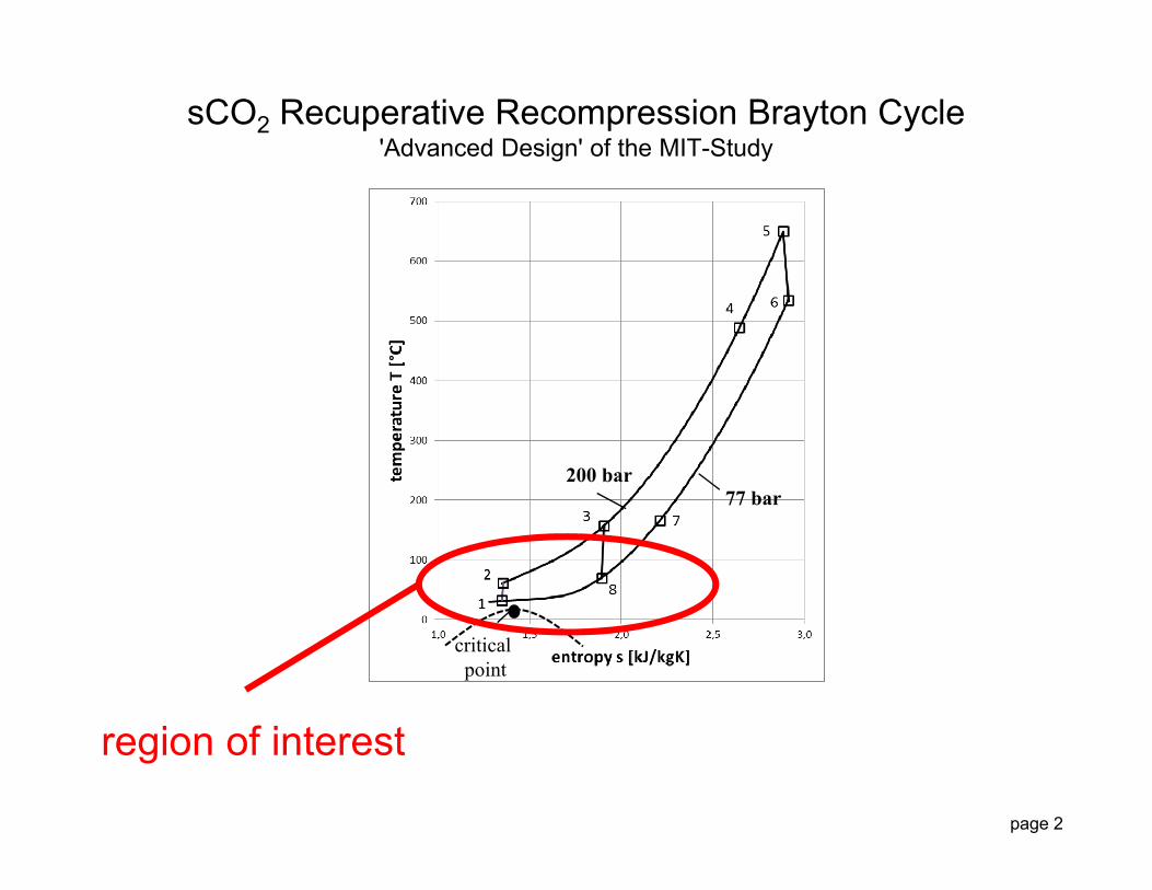
sCO2 Recuperative Recompression Brayton Cycle'Advanced Design' of the MIT-Study
criticalpoint
200 bar77 bar
region of interest
page 3
Outline
Introduction
Test Case : Direct Numerical Simulation (Wang, He)
Dominant Thermal Resistance Approach
Results
Conclusions and Outlook
page 4
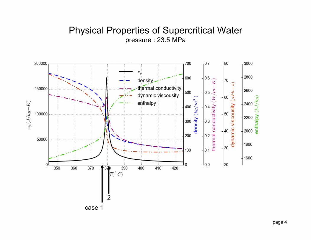
Physical Properties of Supercritical Waterpressure : 23.5 MPa
2case 1

page 5
Approach to provide approximate predictions and improved analyses with varying fluid properties
Possibly a useful basis for extending constant property correlations to variable properties
A reasonable, sensible, simple analysis will (may) provide better predictions than empirical correlations for fluids with significant property variation
Improved treatment for wall functions in CFD
Why Develop an Approximate Method ?
page 6
Outline
Introduction
Test Case : Direct Numerical Simulation (Wang, He)
Dominant Thermal Resistance Approach
Results
Conclusions and Outlook
page 7
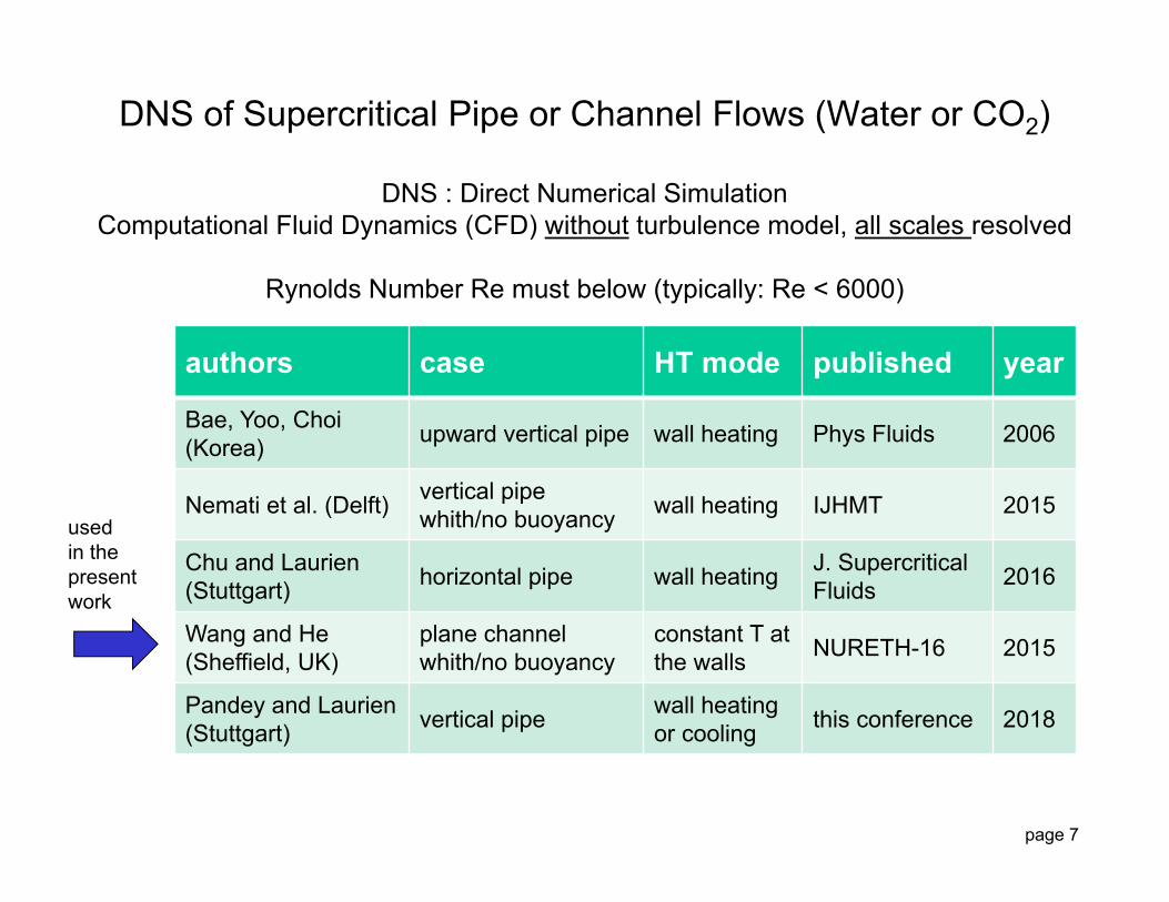
DNS of Supercritical Pipe or Channel Flows (Water or CO2)
DNS : Direct Numerical SimulationComputational Fluid Dynamics (CFD) without turbulence model, all scales resolved
Rynolds Number Re must below (typically: Re < 6000)
authors case HT mode published year
Bae, Yoo, Choi(Korea) upward vertical pipe wall heating Phys Fluids 2006
Nemati et al. (Delft) vertical pipewhith/no buoyancy wall heating IJHMT 2015
Chu and Laurien(Stuttgart) horizontal pipe wall heating J. Supercritical
Fluids 2016
Wang and He(Sheffield, UK)
plane channelwhith/no buoyancy
constant T at the walls NURETH-16 2015
Pandey and Laurien(Stuttgart) vertical pipe wall heating
or cooling this conference 2018
usedin thepresentwork
page 8
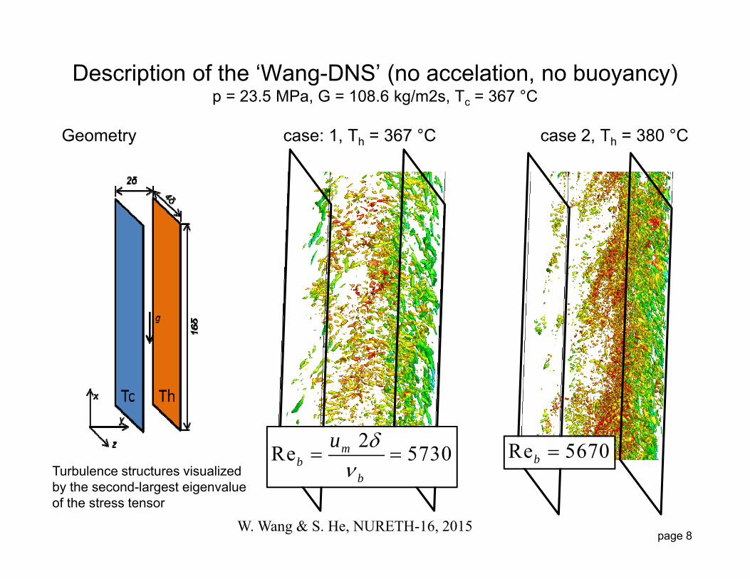
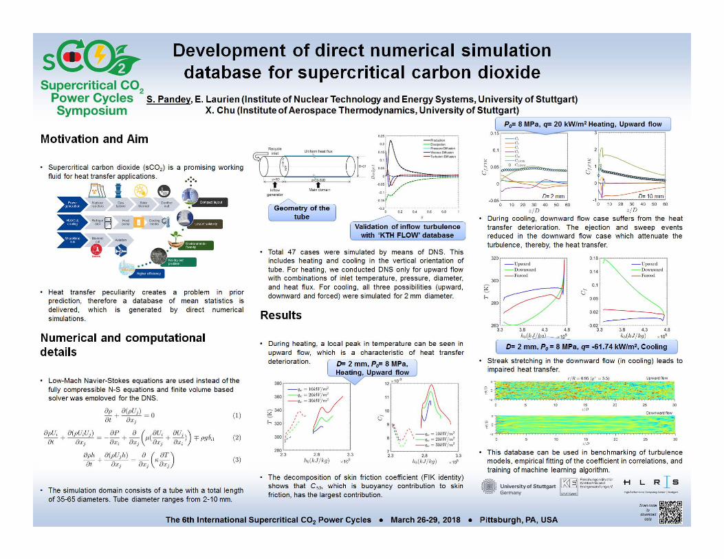
Description of the ‘Wang-DNS’ (no accelation, no buoyancy)p = 23.5 MPa, G = 108.6 kg/m2s, Tc = 367 °C
Geometry case: 1, Th = 367 °C case 2, Th = 380 °C
Turbulence structures visualizedby the second-largest eigenvalueof the stress tensor
W. Wang & S. He, NURETH-16, 2015
2Re 5730mb
b
u
Re 5670b
page 9
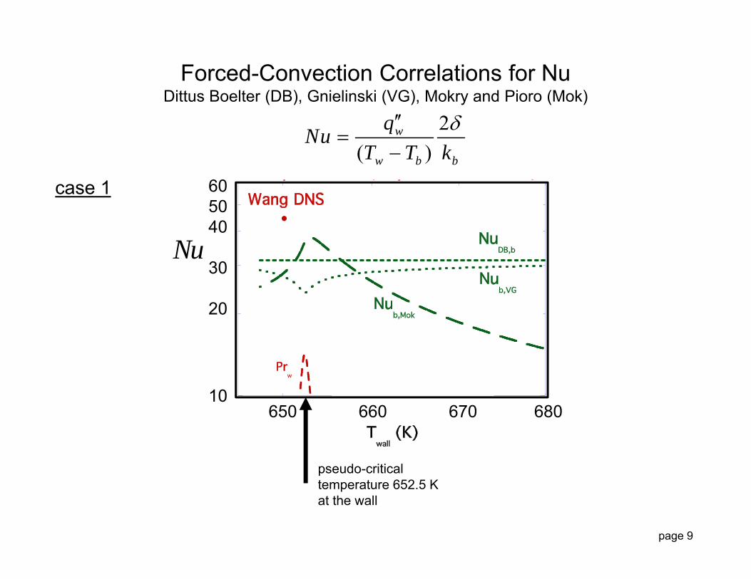
Forced-Convection Correlations for NuDittus Boelter (DB), Gnielinski (VG), Mokry and Pioro (Mok)
605040
30
20
10 650 660 670 680
pseudo-criticaltemperature 652.5 Kat the wall
case 1
Nu
2( )
w
w b b
qNuT T k

page 10
Forced-Convection Correlations for NuDittus Boelter (DB), Gnielinski (VG), Mokry and Pioro (Mok)
30
10
4
2650 660 670 680
pseudo-criticaltemperature 652.5 Kat the wall
case 2
Nu
2( )
w
w b b
qNuT T k

page 12
Importance of the Turbulent CoreDNS data from Bae, Yoo and Choi, Phys. Fluids 2005
/r R
laminarsub layer
y
5 %
page 13
Outline
Introduction
Test Case : Direct Numerical Simulation (Wang, He)
Dominant Thermal Resistance Approach
Results
Conclusions and Outlook
page 14
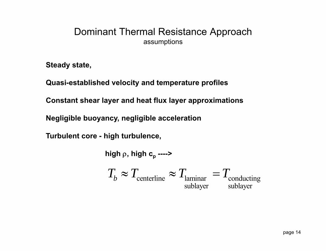
Steady state,
Quasi-established velocity and temperature profiles
Constant shear layer and heat flux layer approximations
Negligible buoyancy, negligible acceleration
Turbulent core - high turbulence,
high , high cp ---->
Dominant Thermal Resistance Approachassumptions
centerline laminar conductingsublayer sublayer
bT T T T
page 15
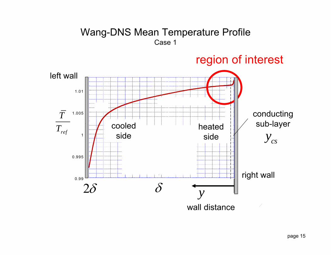
Wang-DNS Mean Temperature ProfileCase 1
0.99
0.995
1
1.005
1.01
-1 -0.5 0 0.5 1
WangF653-Profs-T.qpc
2
h
c pc
ref
TT
y2
region of interest
cooledside
wall distance
heatedside
left wall
right wall
conductingsub-layer
csy

page 16
0
0.5
1
1.5
-1 -0.5 0 0.5 1
WangF653-Profs.qpc
2
h
c pc
Wang-DNS Mean Velocity ProfileCase 1
U
y2
region of interest
wall distance
ucooledside
heatedside
viscoussub-layer
vsy

page 17
Integration of the Thermal Energy Equationin the laminar, conducting sub-layer: the region of dominant thermal resistance
0 ( ) .p wT qc U q y const qx y
Near the wall we have Fourier‘s law:
( ) ( ) Tq y k Ty
Define
( )
0
( ) ( )w
y T y
T
q y d y k T d T Integrate:
( ) ( )ref
T
T
T k T d T a property
then
( ) ( )b ww
cs
T Tqy
At y = ycs
( ) ( )w wq y T T
May be a good approximationIf one has a good estimateof ycs
page 18
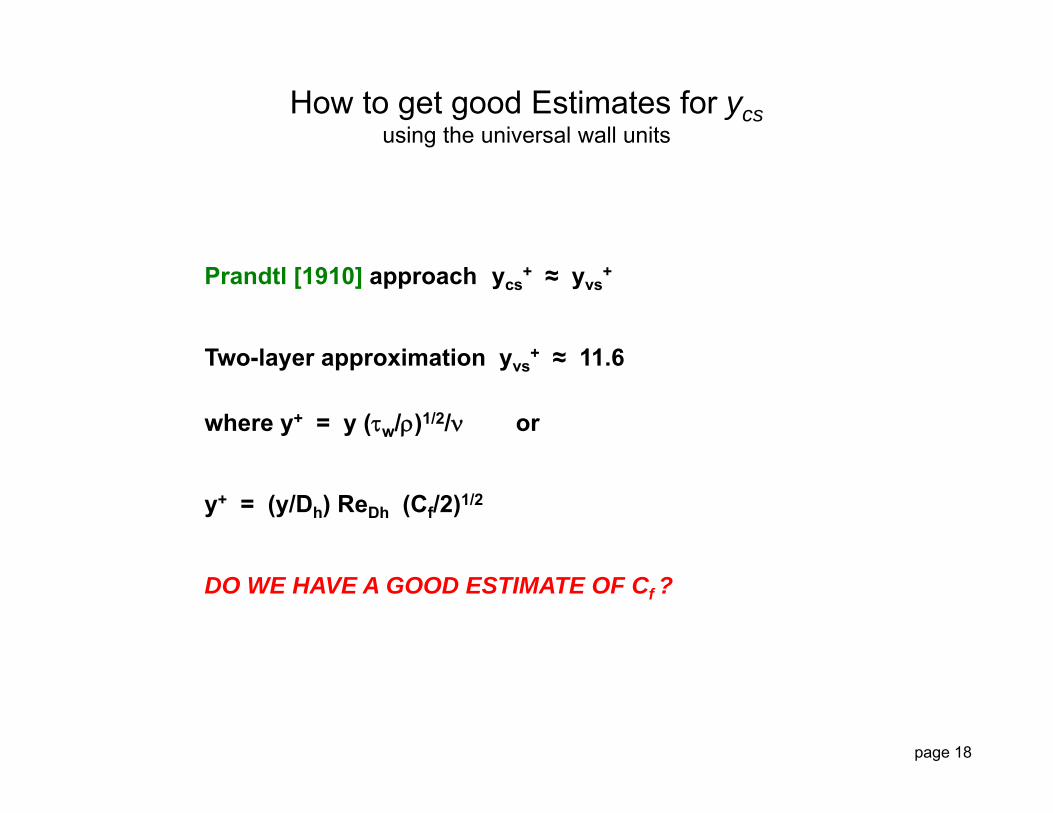
Prandtl [1910] approach ycs+ ≈ yvs
+
Two-layer approximation yvs+ ≈ 11.6
where y+ = y (w/)1/2/ or
y+ = (y/Dh) ReDh (Cf/2)1/2
DO WE HAVE A GOOD ESTIMATE OF Cf ?
How to get good Estimates for ycsusing the universal wall units

page 19
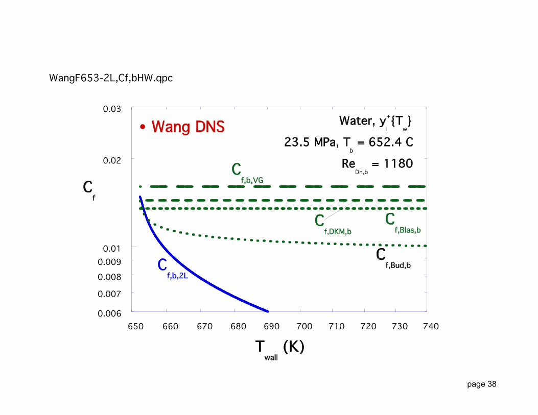
Forced-Convection Correlations for wall friction used in Gnielinski (VG), Drew, Koo, McAdams (DKM), M.F. Taylor (MFT), Blasius (Blas)
660 680 700 720 740
wT K
fccase 1
fc
20.5w
fw m
cu

page 20
Forced-Convection Correlations for Nuused in Gnielinski (VG), Drew, Koo, McAdams (DKM), M.F. Taylor (MFT), Blasius (Blas)
Case 2
660 680 700 720 740 wT K
fc
20.5w
fw m
cu
page 21
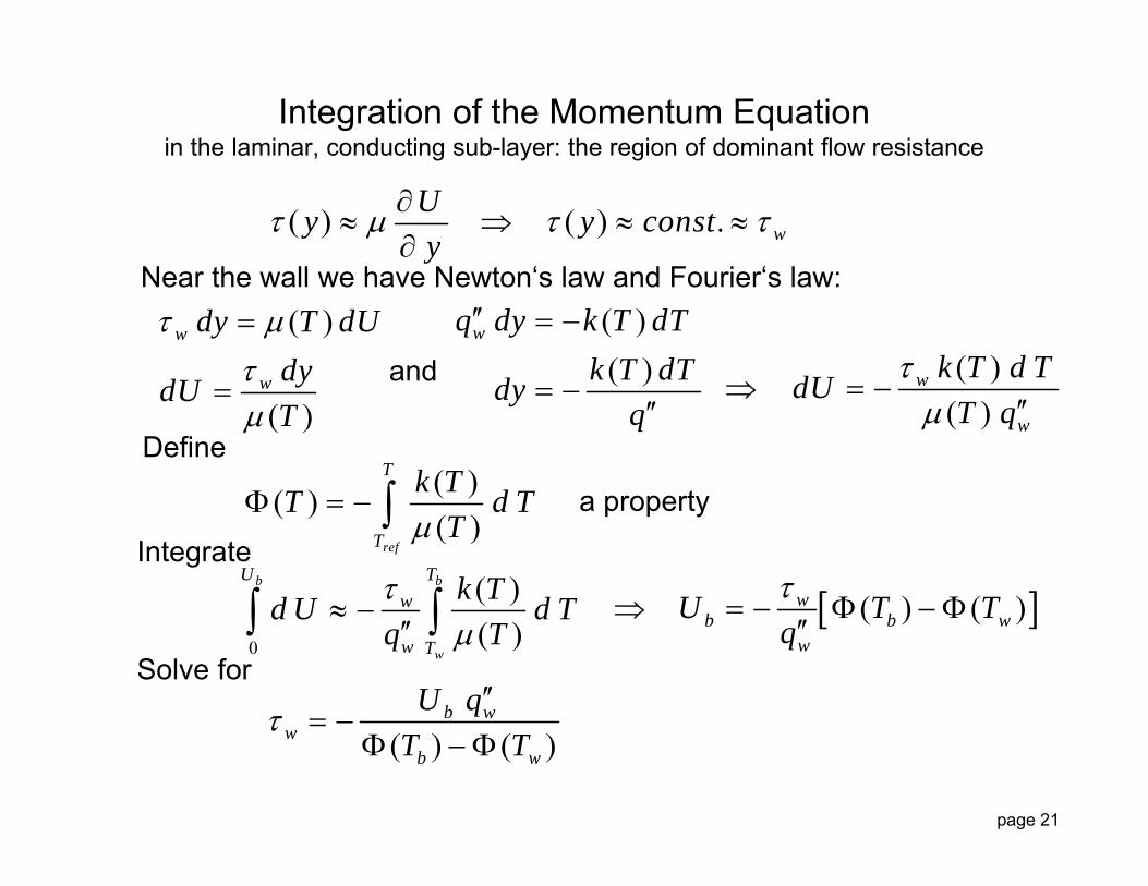
Integration of the Momentum Equationin the laminar, conducting sub-layer: the region of dominant flow resistance
( ) ( ) . wUy y consty
Near the wall we have Newton‘s law and Fourier‘s law:
( )
( )
w
w
dy T dUdydUT
Define
0
( )( )
b b
w
U Tw
w T
k Td U d Tq T
and
( )( )( )
ref
T
T
k TT d TT
a property
( ) ( )wb b w
w
U T Tq
Integrate
( )( )
wq dy k T dTk T dTdy
q
( )( )
w
w
k T d TdUT q
Solve for
( ) ( )b w
wb w
U qT T
page 22
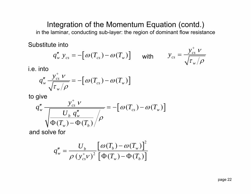
Integration of the Momentum Equation (contd.)in the laminar, conducting sub-layer: the region of dominant flow resistance
( ) ( )w cs cs wq y T T Substitute into
cscs
w
yy
with
( ) ( )csw cs w
w
yq T T
( ) ( )
( ) ( )
csw cs w
b w
w b
yq T TU q
T T
i.e. into
to give
and solve for
2
2
( ) ( )( ) ( ) ( )
b wbw
cs w b
T TUqy T T
page 23
Outline
Introduction
Test Case : Direct Numerical Simulation (Wang, He)
Dominant Thermal Resistance Approach
Results
Conclusions and Outlook
page 24
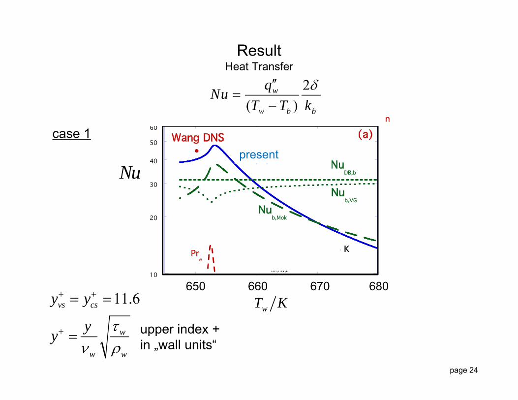
ResultHeat Transfer
case 1present
650 660 670 680
wT K
Nu
11.6vs cs
w
w w
y y
yy
upper index +in „wall units“
2( )
w
w b b
qNuT T k
page 25
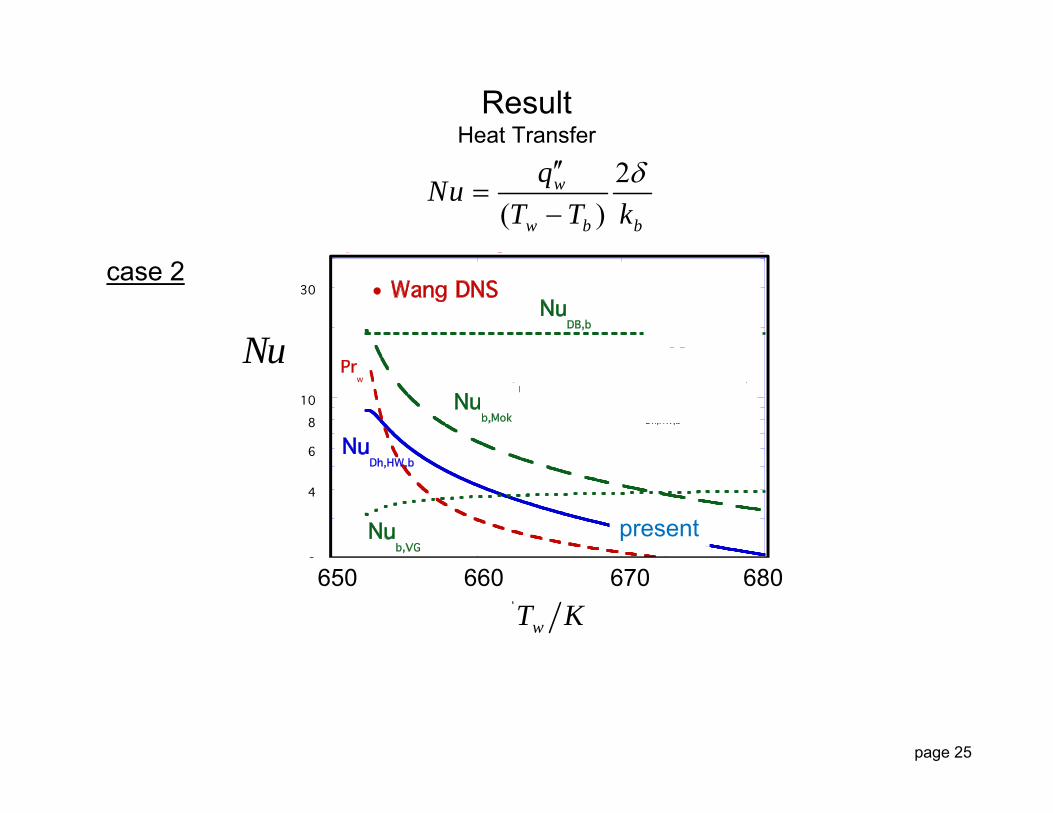
ResultHeat Transfer
case 2
present
650 660 670 680
wT K
Nu
2( )
w
w b b
qNuT T k
page 26
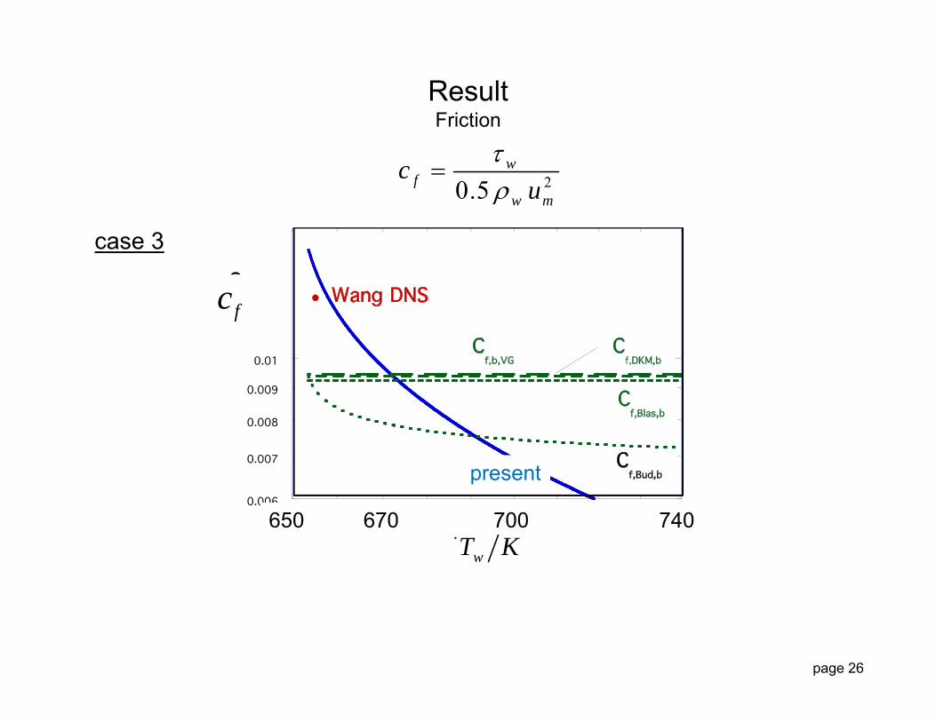
ResultFriction
case 3
present
650 670 700 740 wT K
fc
20.5w
fw m
cu
page 27
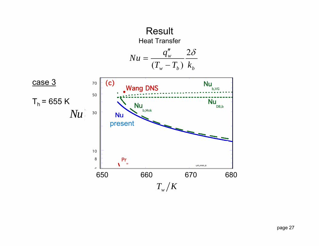
ResultHeat Transfer
case 3
Th = 655 K
present
650 660 670 680
wT K
Nu
2( )
w
w b b
qNuT T k

page 28
Demonstrated a closed-form, approximate, coupled analysis for Nu for ScPF (with negligible buoyancy and acceleration)
Some reasonable agreement with DNS of Wang+He
Nu is sensitive to choice of yvs+
Useful approach to provide approximate predictions and improved analyses
Improved treatment for wall functions in CFD
Can provide a first estimate for interative processes in "more sophisticated" analyses
Concluding Remarks
page 29
Extend to significant buoyancy and acceleration
Revise analysis to treat differing ycs+ and yvs
+
Add thermal resistance for turbulent core?
Outlook
page 30
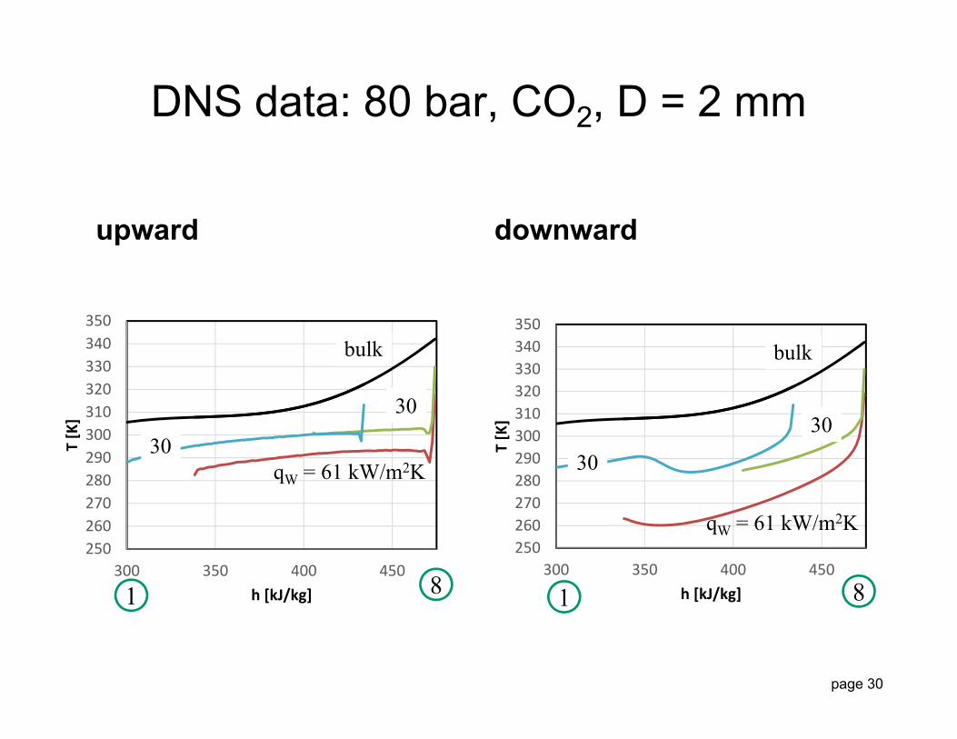
DNS data: 80 bar, CO2, D = 2 mm
upward downward
250260270280290300310320330340350
300 350 400 450
T [K]
h [kJ/kg]
250260270280290300310320330340350
300 350 400 450
T [K]
h [kJ/kg]1 18 8
qW = 61 kW/m2K30
bulk
qW = 61 kW/m2K
30
3030
bulk

page 31
Backup Slides
page 32
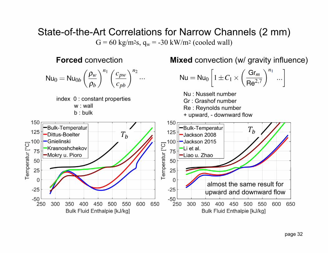
Forced convection Mixed convection (w/ gravity influence)
almost the same result forupward and downward flow
State-of-the-Art Correlations for Narrow Channels (2 mm)G = 60 kg/m2s, qw = -30 kW/m2 (cooled wall)
index 0 : constant propertiesw : wallb : bulk
Nu : Nusselt numberGr : Grashof numberRe : Reynolds number+ upward, - downward flow
page 33
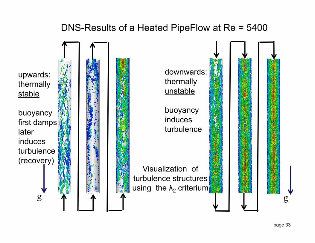
DNS-Results of a Heated PipeFlow at Re = 5400
upwards:thermallystable
buoyancyfirst dampslaterinducesturbulence(recovery)
downwards:thermallyunstable
buoyancyinducesturbulence
Visualization of turbulence structures using the λ2 criterium
g g

page 34
0 50 100 150 200T [°C]
100
10
p[bar]
73.1
30.9
coolingcriticalpoint
pseudo-critical line
bulk temperature (Tb) of aheated/cooled pipe/channel
pseudo-criticalpoint (ppc, Tpc)
ρ = 100 kg/m3
50
150
200250300
saturation line
heating
Terminologyof Single-Pipe or Channel Experiments at Super-Critical Pressure

page 35
sCO2 Recuperative Recompression Brayton Cycle'Advanced Design' of the MIT-Study: Net Efficiency ~47 %
RejectHX
InputHX
MainCompressor
Alternator
Re-Com-pressor
HighTempRecuperator
Low TempRecuperator
Turbine
60%
40%
6 12
34
5
7 8
200 bar
77 bar p TMPa °C
1 7,7 32,02 20 61,13 20 157,14 20 488,85 20 650,06 7,7 534,37 7,7 165,88 7,7 68,9
critical point
200 bar77 bar
region of interest

page 36
Example: Two-Layer Model for Turbulent Boundary LayersPrandtl 1910, Kays and Crawford 1980, constant properties
T
y
lT
bTT R
2R D
pw p
w
c uT y T T y c u R
q
The temperature in wall units
Can be considered a non-dimensional thermal resistance. Expand to
p lam turbT y c u R R
And compare to the Kays and Crawford relation
PrPr ln lntlam lam bT R y R y T
The total resistance is the sum of two individualresistances fore the two layers
wT turbulentcore layer
laminarsub-layer

page 37
page 38