the directed heavy atom effect: by a dissertation
TRANSCRIPT

The Directed Heavy Atom Effect:
A Design Principle for Metal-Free Organic Phosphors
by
Onas James Bolton
A dissertation submitted in partial fulfillment
of the requirements for the degree of
Doctor of Philosophy
(Materials Science and Engineering)
in The University of Michigan
2010
Doctoral Committee:
Associate Professor Jinsang Kim, Chair
Associate Professor Lingjie Guo
Assistant Professor Max Shtein
Assistant Professor Anton Van der Ven

© Onas James Bolton
2010

ii
For Carrie, Charlotte, and Abby.

iii
Acknowledgements
I first must thank Professor Jinsang Kim. When I first met with Professor Kim I
was an under-utilized engineer at a struggling company, possessor of a modest academic
record, four years removed from college, and clinging to uncertain hope that I be
accepted into graduate school. I can only imagine now what he saw in me then, but
nothing in my time at Michigan is more visible than his commitment to support and
mentor me. The opportunity he gave me is perhaps the greatest professional, and in some
ways personal, gift I have ever received and I will always be in his debt. Thank you,
Professor Kim.
Secondly I must thank my colleague, Dr. Kangwon Lee, whose unbridled success
in his main research is the only reason I was lucky enough to inherit this most interesting
and fruitful project. Without his keen observations none of these findings nor our success
with them would have happened. Thank you, Kangwon.
I would also like to thank the members of our research group and my other
collaborators. In particular Dr. Hyong-Jun Kim, Dr. Myung-Su Kim, Dr. Eun Jeong
Jeong, and Bong-Gi Kim contributed much time as they helped to make devices and new
compounds. Dr. Jae Choel Cho taught me the finer points of chemical synthesis. Laura,
Rob, Donghwan, and Jisama, I will always treasure your camaraderie. The members of
the Shtein Group, Shaurjo Biswas and Steven Morris, were selfless with their time to
fabricate devices and move our materials further. Thanks, all.
The small army of undergraduate students that helped me can certainly not be
forgotten. In the project’s early days Kevin Lin and Matt Gray suffered with me as we
struggled to identify the critical compound. Later Jacqueline Harper, Young-Do Kim,
Sarah Wang, Sunghyun Jeon, and Kevin Yien helped to take the work to new places and
run lots and lots of tests. Lots. Their contributions were all critical. Thanks, guys.
Of course, I thank my family for their support throughout the years. I am the
product of their love and guidance and I hope I make them proud. Thanks to my
Grandparents and siblings. Thanks to Fred and Jean for helping me juggle science and
fatherhood in these last critical months. To Mom and Dad love and thanks for your
enduring support. Thanks for band concerts, cars, food/shelter, tuition, and lessons
learned as I watched from the kindergarten window.
My daughter, Charlotte, and dog, Abby, didn’t contribute a great deal of direct
help. In fact, their disregard for my privacy and pointed distain for my focus while
writing this seemed, at the time, quite counterproductive. Still, they are both ridiculously
cute and having two adorable cherubs at constant play on the center stage of my life gives
the entire performance its truest purpose. Hugs and kisses.
Lastly and most importantly, I must thank my wife for whom I dedicate all things
I do. My success has come only through her support and patience. Thanks, Carrie.
I love you.

iv
Table of Contents
Dedication……………………………………………………………………………… ii
Acknowledgements…………………………………………………………………….. iii
List of Figures………………………………………………………………………….. viii
List of Tables………………………………………………………………………….. xi
List of Schemes………………………………………………………………………… xii
Abstract………………………………………………………………………………… xiii
Chapter 1: Introduction and Background……………………………………………… 1
1.1 Fluorescence and Phosphorescence..………………………………….. 2
1.1.1 Singlets and Triplets……………………………………………….. 2
1.1.2 Excited State Transitions………………………………………….. 4
1.2 Characterizations and Measurements………………………………….. 8
1.2.1 Absorption, Emission, and Excitation Spectra…………………….. 8
1.2.2 Quantum Yields……………………………………………………. 9
1.2.3 Quantum Lifetimes………………………………………………… 10
1.2.4 Rate Constants…………………………………………………….. 11
1.3 Phosphorescent Applications………………………………………….. 12
1.3.1 Organic Light Emitting Diodes……………………………………. 12
1.3.2 Photovoltaic Devices………………………………………………. 16
1.3.3 Sensors…………………………………………………………….. 16
1.3.4 Biological Imaging………………………………………………… 17
1.4 Known Organic Phosphors…………………………………………….. 18
1.4.1 Organometallic Chelates…………………………………………… 18
1.4.2 Aromatic Ketones………………………………………………….. 20
1.4.3 Confined Aromatics……………………………………………….. 20
1.4.4 Thiones……………………………………………………………. 21
1.5 Conclusions…………………………………………………………….. 22
1.6 References……………………………………………………………… 23
Chapter 2: Molecular Design of Metal-Free Organic Phosphors……………………… 26
2.1 Challenges to Organic Phosphor Design………………………………. 27
2.1.1 Intersystem Crossing……………………………………………….. 27
2.1.2 Vibrational Dissipation…………………………………………….. 27
2.2 Directed Heavy Atoms (DHAE)……………………………………….. 28
2.3 Aromatic Ketones……………………………………………………… 28
2.3.1 Intersystem Crossing……………………………………………….. 28
2.3.2 Spin-Orbit Coupling……………………………………………….. 30
2.3.3 Vibrational Suppression……………………………………………. 31
2.3.4 Applied in DHAE………………………………………………….. 32
2.4 The Heavy Atom Effect……………………………………………….. 32
2.4.1 Background………………………………………………………… 33
2.4.2 Internal and External Effects………………………………………. 33
2.4.3 Applied in DHAE………………………………………………….. 34

v
2.5 Halogen Bonding………………………………………………………. 35
2.5.1 Background………………………………………………………… 35
2.5.2 Electron-deficient Halogens……………………………………….. 36
2.5.3 Distances and Angles………………………………………………. 37
2.5.4 Applied in DHAE………………………………………………….. 38
2.6 Vibrational Limitation…………………………………………………. 38
2.6.1 Low temperatures………………………………………………….. 38
2.6.2 Polymer/Crystal Embedding……………………………………….. 39
2.6.3 Applied in DHAE………………………………………………….. 39
2.7 Conclusions…………………………………………………………….. 40
2.8 References……………………………………………………………… 41
Chapter 3: The Directed Heavy Atom Effect at Work in Substituted
Benzaldehydes……………………………………………………………. 42
3.1 Introduction…………………………………………………………….. 43
3.2 Results and Discussion………………………………………………… 43
3.2.1 Crystal Structure…………………………………………………… 43
3.2.2 Photophysical Properties: Solution………………………………… 44
3.2.3 Photophysical Properties: Crystal………………………………….. 47
3.3 Experimental…………………………………………………………… 50
3.3.1 General Methods…………………………………………………… 50
3.3.2 Synthesis and Characterization…………………………………….. 51
3.4 Conclusions…………………………………………………………….. 53
3.5 References……………………………………………………………… 54
Chapter 4: Cocrystallization for Enhanced Brightness from DHAE………………….. 55
4.1 Introduction……………………………………………………………. 56
4.2 Optical Results and Discussion………………………………………… 57
4.2.1 Photophysical Properties: Br6………………………………………57
4.2.2 Photophuscial Properties: Cocrystals………………………………. 59
4.3 Cocrystallization……………………………………………………….. 61
4.3.1 Crystal Comparisons……………………………………………….. 61
4.3.2 Cocrystallization Efficiency……………………………………….. 63
4.3.3 Size Constraints……………………………………………………. 67
4.4 Experimental…………………………………………………………… 68
4.4.1 General Methods…………………………………………………… 68
4.4.2 Synthesis and Characterization…………………………………….. 69
4.5 Conclusions…………………………………………………………….. 71
4.6 References……………………………………………………………… 73
Chapter 5: Principles for Color Tuning……………………………………………….. 74
5.1 Introduction………………………………………………………………. 75
5.2 Fine Tuning…………………………………………………………….. 75
5.2.1 Halogen Variations………………………………………………… 75
5.2.2 Halogen-free Chromophore……………………………………….. 77
5.3 Broad Tuning………………………………………………………….. 79
vi
5.3.1 Blue………………………………………………………………… 80
5.3.2 Yellow……………………………………………………………… 82
5.3.3 Orange……………………………………………………………… 83
5.3.4 Red…………………………………………………………………. 86
5.4 Experimental…………………………………………………………… 88
5.4.1 General Methods…………………………………………………… 88
5.4.2 Synthesis and Characterization…………………………………….. 88
5.5 Conclusions…………………………………………………………….. 96
5.6 References……………………………………………………………… 98
Chapter 6: Delayed Phosphorescence………………………………………………….. 99
6.1 Introduction and Background………………………………………….. 100
6.1.1 Delayed Fluorescence……………………………………………… 100
6.1.2 Excimers…………………………………………………………… 101
6.2 Results and Discussion………………………………………………… 102
6.3 Experimental…………………………………………………………… 106
6.3.1 General Methods…………………………………………………… 106
6.3.2 Synthesis and Characterization…………………………………….. 107
6.4 Conclusions…………………………………………………………….. 107
6.5 References……………………………………………………………… 108
Chapter 7: Dimethoxybromobenzaldehyde……………………………………………. 109
7.1 Introduction……………………………………………………………. 110
7.2 Results and Discussion ……………………………………………….. 110
7.3 Experimental…………………………………………………………… 115
7.3.1 General Methods…………………………………………………… 115
7.3.2 Synthesis and Characterization…………………………………….. 116
7.4 Conclusions……………………………………………………………….. 117
7.5 References………………………………………………………………… 119
Chapter 8: Ester Functionalized Phosphors……………………………………………. 120
8.1 Introduction…………………………………………………………….. 121
8.2 Results and Discussion………………………………………………… 122
8.3 Experimental…………………………………………………………… 125
8.3.1 General Methods…………………………………………………… 125
8.3.2 Synthesis and Characterization…………………………………….. 126
8.4 Conclusion…………………………………………………………….. 128
8.5 Reference………………………………………………………………. 129
Chapter 9: Polymer Entanglement…………………………………………………….. 130
9.1 Introduction………………………………………………………………. 131
9.2 Results and Discussion…………………………………………………… 131
9.3 Experimental……………………………………………………………… 139
9.3.1 General Methods…………………………………………………… 139
9.3.2 Synthesis and Characterization……………………………………. 139
9.4 Conclusion…………………………………………………………….. 140

vii
9.5 Reference……………………………………………………………… 142
Chapter 10: Conclusions……………………………………………………………….. 143
10.1 Summary……………………………………………………………….. 143
10.2 Future Considerations…………………………………………………. 148
10.3 References……………………………………………………………… 150

viii
List of Figures
Chapter 1
Figure 1.1 Electron spin diagram showing singlet and triplet states…………………. 3
Figure 1.2 Energy diagram showing important excited state transitions…………….. 5
Figure 1.3 Demonstrative fluorescent decay curve………………………………….. 11
Figure 1.4 A sampling of phosphorescent applications……………………………… 13
Figure 1.5 Examples of known organic phosphors………………………………….. 19
Chapter 2
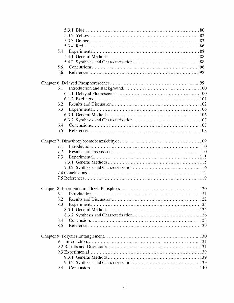
Figure 2.1 Non-bonding molecular orbitals of a carbonyl (formaldehyde)………….. 29
Figure 2.2 S1-T2 intersystem crossing in aromatic ketones (benzophenone)………… 29
Figure 2.3 Benzaldehyde, acetophenone, and benzophenone……………………….. 32
Figure 2.4 Bromine at an ideal position to exert the heavy atom effect and promote
spin-orbit coupling in benzaldehyde……………………………………… 34
Figure 2.5 Cocrystal structure of bromine and 1,4-dioxane………………………….. 35
Figure 2.6 Calculated electrostatic potential surfaces of bound halogens.
Reproduced from P. Auffinger, F.A. Hays, E. Westhof, and P.S. Ho
Proc. Natl. Acad. Sci. 2004, 48, 167891…………………………………. 36
Figure 2.7 Characteristic distance and angles in Br..O halogen bonds………………. 38
Chapter 3
Figure 3.1 Chemical structure of Br6A……………………………………………… 43
Figure 3.2 Crystal structure of Br6A………………………………………………… 44
Figure 3.3 Hypothesized energy diagram of Br6A…………………………………. 45
Figure 3.4 UV-Absorption, PL emission, and PL excitation of Br6A in chloroform
and methanol solutions…………………………………………………… 46
Figure 3.5 Photo and PL emission spectra of solid state Br6A in various crystal
qualities…………………………………………………………………… 48
Figure 3.6 PL emission of Br6A in glassy toluene at 77K…………………………… 49
Figure 3.7 Phosphorescent lifetime measurement of Br6A crystals…………………. 50
Chapter 4
Figure 4.1 Chemical structure of Br6………………………………………………… 72
Figure 4.2 UV-absorption, PL excitation, and PL emission of Br6 at various
temperatures………………………………………………………………. 58
Figure 4.3 Photo, UV-absorption, PL emission, and PL excitation of solid-state
Br6A/Br6 cocrystals……………………………………………………….59
Figure 4.4 Polarized emission of Br6A/Br6 cocrystal……………………………….. 62
Figure 4.5 Crystal structures of Br6 and Br6A………………………………………. 62
Figure 4.6 Comparing other crystal dimensions of Br6 and Br6A………………….. 63
Figure 4.7 QY versus Br6A content in dropcast cocrystals…………………………. 64
Figure 4.8 Photos of Br6A/Br6 dropcasts magnified to show bright nucleation sites.. 66
Figure 4.9 Structures of Br4-Br8 and Br4A-Br8A as well as QYs measured from a
series of their mixed crystals………………………………………………67

ix
Chapter 5
Figure 5.1 Chemical Structures of Cl6A, Cl6, I6A, and I6………………………….. 76
Figure 5.2 PL emission spectra of Cl6A, Br6A, and I6A each cocrystallized with
Br6 at roughly one weight percent.……………..………………………… 77
Figure 5.3 Chemical structure of H6A………………………………………………. 77
Figure 5.4 PL emission spectrum of H6A/Br6 cocrystal (dotted)…………………… 78
Figure 5.5 PL emission spectra of H6A in solution at 298 and 77K………………… 79
Figure 5.6 Chemical structures of BrAlkyl6A and BrAlkyl6……………………….. 80
Figure 5.7 Photo, PL emission, and PL excitation spectra of BrAlkyl6A/BrAlkyl6
cocrystals…………………………………………………………………..81
Figure 5.8 Chemical structures of BrS6A and BrS6…………………………………. 82
Figure 5.9 Photo, UV-absorption, PL emission, and PL excitation spectra of
BrS6A/BrS6 cocrystals…………………………………………………… 83
Figure 5.10 Chemical structures of Np6A and Np6…………………………………… 84
Figure 5.11 Photo, PL emission, and PL excitation spectra of dropcast and a slow-
grown crystal of Np6A/Np6……………………………………………… 84
Figure 5.12 Crystal structure of Np6………………………………………………….. 86
Figure 5.13 Chemical structures of NpS6A and NpS6……………………………….. 87
Figure 5.14 Crystal structure of NpS6………………………………………………… 87
Chapter 6
Figure 6.1 PL emission and excitation spectra of Br6A and Br6A/Br6 crystals…….. 103
Figure 6.2 Phosphorescent decay curves of Br6A and Br6A/Br6 crystals………….. 103
Figure 6.3 Photo and PL emission and excitation spectra of Br6A crystals at 238 K
and 77 K………………………………………………………………….. 104
Figure 6.4 Excited state diagrams of Br6A crystals at 298 K and 77 K…………….. 105
Figure 6.5 PL emission and excitation of Br6A crystals and Br6A in glassy toluene
solution each at 77 K………………………………………………………106
Chapter 7
Figure 7.1 Structures of Br1A and Br1………………………………………………. 110
Figure 7.2 Quantum yields of dropcast Br1A/Br1 cocrystals at pertinent weight
fractions of Br1A as compared to Br6A/Br6 dropcast cocrystals…………111
Figure 7.3 Photos and crystal structure of Br1A…………………………………….. 113
Figure 7.4 PL emission of Br1A crystals and Br1A/Br1 cocrystals…………………. 113
Figure 7.5 Monodisperse crystals grown from 145oC sublimation of Br1A/Br1 for
various periods of time…………………………………………………….114
Chapter 8
Figure 8.1 Structures of BrE6A and BrE6…………………………………………… 121
Figure 8.2 PL emission and excitation spectra of BrE6A/BrE6 cocrystals………….. 122
Figure 8.3 Crystal structure of BrE6…………………………………………………. 123
Figure 8.4 Selected QY values of BrE6A/Br6E cocrystals as compared to those of
Br6A/Br6 cocrystals……………………………………………………… 124
Figure 8.5 Optical micrographs of BrE6A/BrE6 cocrystals…………………………. 125

x
Chapter 9
Figure 9.1 Structure of BrEHA………………………………………………………. 132
Figure 9.2 PL emission and excitation of BrEHA liquid…………………………….. 133
Figure 9.3 Structures of polymers used to embed BrEHA that succeeded in
generating phosphorescent emission……………………………………… 134
Figure 9.4 PL emission spectra of BrEHA embedded in various polymers………….. 135
Figure 9.5 Optical micrograph of BrEHA/PMMA film……………………………… 136
Figure 9.6 Schematic illustrating the idea of polymer entanglement………………… 137
Chapter 10
Figure 10.1 Schematic representation of the DHAE design principle………………… 145

xi
List of Tables
Chapter 3
Table 3.1 Crystallographic data for Br6A…………………………………………… 53
Chapter 4
Table 4.1 Crystallographic data for Br6…………………………………………….. 71
Chapter 5
Table 5.1 Crystallographic Data for Np6…………………………………………… 96
Table 5.2 Crystallographic Data for NpS6…………………………………………. 96
Chapter 7
Table 7.1 Crystallographic Data for Br1A………………………………………….. 117
Chapter 8
Table 8.1 Crystallographic Data for BrE6……………………………………………128

xii
List of Schemes
Chapter 3
Scheme 3.1 Synthetic route to Br6A……………………………………………….. 51
Chapter 4
Scheme 4.1 Synthetic route to BrN and BrNA…………………………………….. 69
Chapter 5
Scheme 5.1 Synthetic route to Cl6A and Cl6………………………………………. 88
Scheme 5.2 Synthetic route to I6A and I6…………………………………………. 90
Scheme 5.3 Synthetic route to H6A………………………………………………… 90
Scheme 5.4 Synthetic route to BrAlkyl6A, BrAlkyl6, BrS6A, and BrS6………….. 91
Scheme 5.5 Synthetic route to Np6A and Np6……………………………………… 92
Scheme 5.6 Synthetic route to NpS6 and NpS6A………………………………….. 93
Chapter 7
Scheme 7.1 Synthetic route to Br1A and Br1……………………………………… 116
Chapter 8
Scheme 8.1 Synthetic route to BrE6A and BrE6…………………………………… 126
Chapter 9
Scheme 9.1 Synthetic route to BrEHA……………………………………………… 139

xiii
Abstract
Phosphorescent materials are changing the way organic compounds are used in
optical devices. By being more efficient, slower emitting, and uniquely sensitive they are
expanding the applicability of organic materials. In order, though, for this trend to
include all organic materials the critical limitation of an organometallic structure must be
overcome. At the time of this publishing, organometallics alone preform well enough for
applicational use. Here is presented the Directed Heavy Atom Effect (DHAE), a design
principle to realize bright phosphorescence from metal-free organic compounds. By
synergistically combining the phosphorescence-enhancing property of the heavy atom
effect with the heavy atom directing property of halogen bonding, DHAE achieves
organic phosphors with efficiencies competitive to organometallic and inorganic
materials. Here the DHAE is attained by cocrystallizing an aromatic aldehyde with an
optically inert, halogenated analog. These cocrystals exhibit halogen bonding, which
directs the heavy atom to enhance spin-orbit coupling at the carbonyl and activate
phosphorescence. The optically inert host isolates the chromophore from self-quenching,
resulting in unprecedentedly bright metal-free organic phosphorescence. From this
design principle a variety of materials with varying properties are synthesized. Emission
color can be tuned in either fine steps of 5 nm or broad chromic steps from blue to green,
yellow, and orange. Material modifications, DHAE phosphors with controllable, vapor
deposited microstructures or ester functionalization, are also achievable with careful
material design presented here. The novel phenomenon of delayed phosphorescence is
demonstrated from crystals of pure DHAE chromophore, holding promise for enhancing
emissive device efficiencies. To escape design complications, polymeric hosts are
presented as an alternative to crystal systems. If well designed, polymer hosts can
produce bright phosphorescence even from liquid DHAE-style chromophores by
suppressing vibrational dissipation pathways. Finally a broad summation of the work is
offered along with ideas about the future direction of DHAE phosphors.

1
Chapter 1
Introduction and Background
This chapter describes the importance of phosphorescence first by explaining its
fundamental differences to fluorescence. It illustrates the pertinent excited state
transitions that make phosphorescence possible as well as the measurable values used to
examine it and the methods by which they are evaluated. A growing list of commercial
applications for which phosphorescent materials are desirable demonstrates the need for
more organic phosphors then a brief categorical review of known organic phosphors is
presented with their benefits and limitations highlighted. The most important finding in
this report is a new design principle to create bright metal-free organic phosphors and the
concepts presented in this chapter give the reader the background to understand why this
principle works and why the finding is so significant.

2
1.1 Fluorescence and Phosphorescence
Fluorescence and Phosphorescence are both means by which matter emits light, yet
the subtle differences between them make each uniquely useful for specific applications.
To understand the novelty of the work presented here one must grasp the differences
between them and the electronic states and transitions that govern them. These concepts
are explained here at a level of depth sufficient for the average reader. For more
complete descriptions of the quantum mechanical basis of atomic electronic states see
cited references and texts.1,2,3,4
1.1.1 Singlets and Triplets
Electrons are particles with ½ integer spins, they exhibit angular momentum of √3⁄2 ħ
(where ħ is the reduced Plank’s constant). These properties define them as fermions and
limit their position by Fermi-Dirac statistics. No two electrons can occupy the same
quantum state at the same time as per the Pauli exclusion principle, from which Fermi-
Dirac statistics are derived. In order for two electrons to share an orbital they must have
opposite spins, thereby occupying two separate quantum states. In more complete terms,
the total wavefunction of two electrons in an orbital must be anti-symmetric. That is, if
the two electrons were to exchange positions their wavefunction would be inverted. This
is often stated simply as requiring that two electrons in the same molecular orbital have
opposite spins, +½ (↑) and -½ (↓), but the quantum mechanical description of the
wavefunction symmetry under particle exchange is more precise.
For any given system of two electrons there exist four possible orientations of their
collective spin: ↑↑, ↑↓, ↓↓, and ↓↑. From these four possibilities, only one satisfies the
anti-symmetric requirement of the Pauli exclusion principle once we apply particle
exchange:
� =1
√2�↑↓ − ↓↑� = 0
While the other possibilities yield a net spin of 1 and each is symmetric under particle
exchange:
� =1
√2�↑↓ + ↓↑� = 1
� = ↑↑ = 1

3
� = ↓↓ = 1
These states are named accordingly singlet (S=0) and the three degenerate5 triplets (S=1).
Thus only singlets satisfy the Pauli exclusion principle.
It may be difficult to understand why one case of spin-opposite pairing is a singlet
while the other is a triplet. The binary view of spin is a construct that is too simple to
fully explain these states. It is important to remember that spin is a three-dimensional
property of the rotating electron. Figure 1.1 attempts to use vector representation to
illustrate how there exists four possible spin orientations for two electrons. In the
rightmost example both electrons are what might be called spin opposite, but their
resultant spin is actually non-zero in the xy plane because their dipoles are not out-of-
phase. Only when both spins are opposite and out-of-phase do we have a total zero
resultant, a singlet state.6
In the ground state, all electrons in most organic molecules are sharing orbitals as
they are either bonded or coupled as lone pairs. Thus they must be singlets. In excited
states, however, spin orientations are no longer restricted because two of the electrons are
no longer sharing an orbital. While excited either of those electrons have the freedom to
change their spin as they now exist in partially filled orbitals. This process is often
referred to colloquially as flipping and technically as intersystem crossing. Under first
order approximations, however, this is strictly disallowed as it does not conserve angular
Singlet: electrons are spin
opposite and out-of-phase.
There is zero resultant.
Triplets: electrons are either spin parallel or in phase. Each has a
non-zero resultant.
Figure 1.1 Electron spin diagram showing singlet and triplet states. Recreated from
Turro.3 Precession is important to whether the vectors are perfectly out-of-phase.
z

4
momentum. The total spin changes from 0 to 1 or vice versa during flipping. As will be
discussed later, though, certain second order external effects can mix singlet and triplet
states making intersystem crossing possible and in some cases very efficient.
In molecules there exist a large number of orbitals whose wavefunctions can be either
antisymmetric (singlets) or symmetric (triplets), though, as stated, ground state
configurations for most organic molecules contain orbitals that are all singlets. A
theoretically infinite number of singlet states exist for any molecule and are numbered in
order of increasing energy, S1 to Sn. The ground state is often referred to as S0, since it is
also a singlet and the lowest in energy.
Molecules also posses potential triplet state configurations, though they are rarely
populated when the molecule is not in an excited state. Triplet states are numbered also
by increasing energy from T1 to Tn. T0 does not exist for most organic compounds
because there is no ground state triplet (molecular oxygen is a notable exception).
Ground states in nearly all organic molecules are fully bonded or paired requiring all
orbitals to be singlets. Chemists can think of electrons in triplet states as diradicals: the
excited state molecule contains two non-bonding, unpaired electrons.
1.1.2 Excited State Transitions
In order to understand the fundamental differences between fluorescence and
phosphorescence and to see how we can analyze the materials described in this work it is
important to understand what exactly is happening to the electrons of an excited
molecule. Described here are the primary actions of an optically active organic molecule.
While much of this description applies to non-organic materials as well, this is written
with organic molecules in mind. Figure 1.2 illustrates each of the transitions described in
this section.

5
When an organic molecule is struck by a photon whose energy is equal to the gap
between the molecule’s ground state, S0, and any of its higher energy singlet states Sn
(where n > 0) it may absorb that photon’s energy to become excited. The photon acting
on the molecule is referred to as the excitation light and the molecule is then in one of its
excited states. This process is absorption. It is a spin-conserving phenomenon meaning
that it allows only for singlet-to-singlet transitions. For many organic molecules the S0
→ S1 transition falls with the range of visible light. Higher order transitions, S0 → S1+n,
are possible but most likely to relax quickly to S1 by Kasha’s Rule.7 Thus S1 is typically
where the excited state molecule begins its excited state activity. The shorthand
representation of absorption is S0 + hν → S1.
Once excited by absorption the excited electron undergoes a small amount of
vibrational relaxation. This is caused by the subtle changes the overall molecular
structure undergoes once the two electrons in question are no longer bonded. With the
excited electron no longer sharing orbital space with the ground state electron there is less
attractive force between their two nuclei. The molecule, like balls connected by springs,
shifts to stabilize this new electronic arrangement. This manifests in a slight relaxation of
S1
S0
S2
Sn
S1
S0
S2
Sn
T1
T2
Tn
hν (Fl)
hν (Ph)
Figure 1.2 Energy diagram showing important excited state transitions. (A)
Absorption transitions with inset highlighting vibrational modes of S1 (vibratioanl
modes exist but are not shown here for other states). (B) Excited state transitions.
Quantum transitions are identified by solid arrows, vibrational transitions have
dotted lines, and intersystem crossings are dashed. (Note that both transitions
from T1 to S0 are technically also considered intersystem crossing.)
hν
Vibrational
Modes of S1
A B

6
the excited electron. The small steps via which it does this relaxing are the vibrational
modes of the excited state. These modes exist for every excited state (including S0), are
usually numerous but small in energy, can be affected by environment and configuration,
and are greatly affected by temperature. That last point means that at low temperature
nuclear movement is restricted and some, perhaps all, vibrational modes become
inaccessible. Figure 1.2 shows vibrational modes as an inset to the energy diagram.
From S1 there are three possible actions the excited electron can take, which are each
depicted in Figure 1.2. The first and often most favorable is fluorescence, which is
emissive, quantum relaxation from the singlet state. This is most favorable because in S1
both the excited and ground state electrons are in their original spin orientation, which
makes direct quantum relaxation very rapid. For most organic molecules fluorescent
relaxation usually occurs in picosecond or nanosecond timescales. In shorthand
fluorescence is S1 → S0 + hν .
The second route is internal conversion, sometimes referred to as vibrational
dissipation. Just as vibrational modes allow for S1 to relax somewhat following
absorption, there may be sufficient modes to allow S1 to relax completely to S0. This
may be an internal function or made possible by vibrational interaction with neighboring
molecules (solvents for example). The result is that the absorbed photon’s energy is
eventually lost to vibrational energy, heat. Figure 1.2 shows this route as a dotted arrow.
The shorthand is S1 → S0 + heat.
The third most common route to singlet relaxation is intersystem crossing. This is the
process by which singlets become triplets. It occurs when one or both of the electrons
change their spin. The process requires a non-conserving change in spin, forbidden by
first order approximations. Changes to the angular momentum of the electron are
possible but only by typically weak second order interactions (described in Chapter 2),
which make intersystem quite slow and typically uncompetitive with fluorescence and/or
internal conversion. Once formed the triplet state itself is more stable than the singlet
(with one famous exception8) because of Hund's Rule of Maximum Multiplicity.
9 The
change in electronic configuration of T1 is usually more dramatic than that of S1, causing
greater conformational change and enhanced relaxation. Figure 1.2 shows intersystem
crossing as a dashed arrow between S1 and T1. Its shorthand is S1 → T1.

7
From T1 there are roughly the same transitions available that were to S1. Just as
vibrational modes allowed for S1 to relax slightly, or completely, T1 has its own
vibrational modes to achieve the same. T1, however, is of much lower energy than S1 and
the possibility of complete relaxation from T1 to S0 is much, much greater. Fewer modes
are required to completely relax the excited state. Furthermore, because relaxation from
T1 to S0 requires slower second order interactions, quantum relaxation is very slow and
very non-competitive with vibrational decay. This form of internal conversion, T1 → S0
+ heat, is shown in Figure 1.2 as a zig-zagging line from T1 to S0.
Emissive relaxation from T1 is phosphorescence.10
A photon is emitted as the excited
state electron relaxes while returning to its original spin state. Because this process
involves intersystem crossing, which requires slow spin flipping, phosphorescent
emission is slow to occur following absorption. Thus phosphorescence is observed on a
much longer timescale than fluorescence. For organic molecules this is usually
microseconds to milliseconds, but can be as long as seconds and beyond. Figure 1.2
shows this transition as a straight arrow with a wavy arrow to indicate the photon. The
shorthand is T1 → S0 + hν.
Unlike S1, there is no intrinsic excited state lower than T1. Thus there is no
intersystem crossing from T1 to a lower excited state. S1 is, by definition, the lowest
energy singlet and T1 is lower than that. Triplets though are very susceptible to
intermolecular interaction, due to their long lifetimes. Numerous lower energy states are
possible via these interactions, but they can be thought of simply as additional paths to
internal conversion as they almost always lead to vibrational dissipation. It is important
to this work, however, to note this susceptibility as triplet isolation is critical to achieving
efficient phosphorescence. This is discussed further in chapters 2 and 3.
Now we can understand the critical differences to fluorescence, singlet emission, and
phosphorescence, triplet emission. Those key differences are degeneracy, speed, and
susceptibility. The degeneracy of the triplet states means that phosphorescent molecules
emit light from three excited states, the three states that comprise T1, while fluorescent
molecules emit from only one, S1. Speed refers to the greatly extended lifetimes of
triplets and phosphorescence. Being that the two are orders-of-magnitude separated,
phosphorescence is easily distinguished from fluorescence. Finally susceptibility, the

8
relatively sensitive nature of triplets, often quenched by a wide variety of external
stimuli, gives phosphorescent molecules unique properties useful for detection and
imaging.
1.2 Characterizations and Methods
In the study of phosphorescent molecules it is critical to understand not only the
measurables of the system and how to measure them but also the importance of the
measurement condition and technique. This section explains the importance and detail of
the data and the methods used to collect them.
1.2.1 Absorption, Emission, and Excitation Spectra
Spectral data can tell a great deal about the excited states of molecules. Absorption
spectroscopy will tell us no more than what wavelengths of light the molecule absorbs at
relative intensities. It does not give any indication of the excited state transitions other
than absorption, S0 + hν → Sn>0. The width and shapes of the peaks seen in the spectrum
indicate the vibrational modes of S1 that are populated, but do not necessarily indicate
where S1 will come to be once it has equilibrated.
Absorption spectroscopy is typically, and in this report, taken by transmittance. A
beam of light is passed through the sample and the amount of signal attenuation is
measured as the beam wavelength is changed. The relative intensities give a spectrum
showing which wavelengths are absorbed by the sample.
Emission spectroscopy is quite simple. It gives the spectrum of light produced by the
sample after excitation. In this work, all excitations are achieved by photon absorption.
This makes the reported emission photoluminescent (PL) emission, luminescence that is
excited by photons. Emission spectra tell us final levels of S1/T1and its vibrational
modes, which are represented by the width and shape of the emission peak(s).
Excitation spectroscopy probes the absorption spectrum for those wavelengths that
cause the sample to emit. Each wavelength absorbed by the sample raises the ground
state electron to a different vibrational mode and singlet state and not all modes/states
may lead ultimately to emission. Excitation spectra reveal the emissive states of a
chromophore and yield information about the excited-to-ground state transitions where
absorption spectroscopy probes only the ground-to-excited state transitions.

9
Both emission and excitation spectroscopy are measured by exposing the sample to
an incident beam of light and measuring the output light coming from the sample.
Emission spectroscopy varies the detector wavelength to scan all possible emissions
given a single excitation wavelength. Excitation spectroscopy varies the incident light to
scan all possible excitations given a single emission wavelength. In both cases the
incident beam and detector are oriented at 90o from each other to reduce observation of
the incident light. Spectra measured here are done in the steady state, meaning that no
dynamic data can be interpreted from the emission or excitation spectra presented.
1.2.2 Quantum Yields
An important measurable for understanding the excited state activity of a molecule is
the quantum yield (QY). QY is defined by equation 1.1.
Φ = (photons emitted) / (photons absorbed) (1.1)
Φ is the QY as a unit-less fraction, a measurement of how efficiently the molecule emits
from a certain amount of excitation. Absorption is absolute and all photons that a
molecule absorbs lead to an excited state, which must relax somehow. The QY tells us
the probability that an excited state relaxes by emission and can yield valuable clues as to
the excited state activity of the molecule.
There are several ways to measure QY and there is considerable variance to the style
of measurement and resulting number. Because these tests are highly susceptible to
variance it is difficult to compare the measurements of different researchers with fine
accuracy. Errors between users can be more than ten percent, but careful measurement
practice and sound sample preparation can limit this to well below a single percent. As
such these numbers must be given with adequate statistical error to be useful and should
be compared across measurement method with suspicion.
The use of a standard is quite common for homogenous samples such as solutions and
polymer films. The sample’s emission intensity is measured against a known standard in
the same excitation conditions. Though this method uses a standard, it is still highly
dependent on stable conditions between measurements. Excitation light intensity and
wavelength, temperature, and all other conditions must be exactly the same to make a
comparison between the standard and the sample. This test also assumes and demands

10
perfect homogeneity of the chromophore in the sample. If either the standard or the
sample contains any anisotropy the comparison between them is invalid.
Integrating spheres are often employed to measure QY without the necessity of a
standard or the requirement of a homogenous sample. The device is a hollow sphere
coated on its inside to be perfectly reflective with only ports for the sample, the excitation
light, and the detector inside. The sample is loaded into the sphere and the measurement
assumes that all light that enters the sphere or is generated within the sphere (PL
emission) exits out the detector port. The intensity difference of the excitation beam
when the sample is and is not present in the sphere gives a quantitative value for
absorbance by the sample. Emission from the sample can be subtracted from any
background emission from the empty sphere to get a quantitative value of emission. The
two can be divided to calculate the QY. This method also requires stable conditions
between measurements (sample-in and empty sphere, ‘blank’) and it makes assumptions
about the perfection of the sphere and its reflective properties, which is admittedly
imperfect as the sphere has at least three ports disturbing its surface.
For the purposes of this report an integrating sphere was used. The samples studied
were very inhomogeneous and not viable for measurement by comparison to a standard.
1.2.3 Quantum Lifetimes
The speed at which an excited state molecule exhibits PL emission is measured as a
quantum lifetime. The general relationship is given in equation 1.2.
I = I0 e(-t/τ)
(1.2)
I is the emission intensity, I0 is the initial emission intensity, t is time elapsed since
excitation, and τ is the quantum lifetime in units of time. The excited states experience
exponential decay reflective of the stability of the state.
As mentioned, phosphorescence is triplet emission. Triplets require much more time
than singlets to emit so phosphorescence typically has a quantum lifetime much longer
than that of fluorescence. For organic molecules, τFl is typically in a picosecond to
nanosecond regime while τPh can be microseconds to seconds.
Quantum lifetimes are calculated by measuring the intensity of emission at certain
times after the incident absorption light is applied. A decay curve is observed and fit to
equation 1.2 to determine τ. Figure 1.3 shows a typical curve for a fluorescent organic

11
molecule. Pulsed lasers are often used as the light source as they provide short bursts of
excitation light (so that the excitation does not interfere with the potentially much weaker
signal emission). For short lifetimes, such as those of a fluorescent event, equipment
response times can complicate the measurement and must be corrected for. Complicated
systems may exhibit several simultaneous emissions, but each can be modeled neatly by
equation 1.2, they simply require de-convolution from a single observed decay signal.
The lifetimes reported here were collected using both pulsed laser sources and flash
lamps. Flash lamps are slower than pulsed lasers, but they are sufficiently fast for
measuring slower phosphorescent lifetimes. Data is fit to equation 1.2 with the lifetime,
τ, being the critical measurable.
1.2.4 Rate Constants
To understand fundamentally the activity of an excited state molecule and determine
which path(s) the excited electron follows it is important to think of all possible actions
of the electron as competing rates. As stated before, fluorescence is very fast – the
electrons require no additional spin change and the nuclear framework is often not greatly
altered from the ground state – so the rate at which singlets relax to the ground state by
emission is very fast. If one hopes for those singlets to become triplets via intersystem
crossing, the rate at which the electrons flip must be competitive with that of the
fluorescence. Otherwise no singlets will survive to flip into triplets.
I = Ioe(-t/τ)
Slope = -τ
Figure 1.3 Demonstrative Fluorescent Decay Curve. Exponential decay is shown
on a linear scale (left) and semi-log (right).
0
100
200
300
400
500
600
700
0 2 4 6 8 10
Inte
nsity
Time (ns)
1
10
100
1000
0 2 4 6 8 10
Inte
nsity
Time (ns)

12
In general the simple relationship between the rate of a transition and the measurable
values is given in equation 1.3.
k = Φ / τ (1.3)
The rate, k, of any excited state transition is the ratio of its QY, Φ, divided by the speed at
which it acts, τ. For emissive events, fluorescence and phosphorescence, these are easy
to measure; τ is the lifetime. This relationship can give us insight into the relative
competitiveness of routes vying for the electron.
1.3 Applications for Phosphorescence
The subtle differences between fluorescence and phosphorescence give the later
unique advantages in a number of emerging technologies. The critical differences are the
degeneracy of the triplet states, the far longer lifetimes of triplets versus singlets, and the
sensitivities of triplets to a wider array of quenching conditions. The unique properties of
phosphorescent materials are not only opening organic materials to new technologies but
also garnering them new popularity in already popular fields.
1.3.1 Organic Light Emitting Diodes
The highest profile application for phosphorescent materials is in the field of organic
light emitting diodes (OLEDs). Because of the degeneracy that exists with triplets
phosphorescent materials have an advantage over fluorescent materials. In OLEDs
excited state electrons are injected (as electrical current) while a ground state electron is
extracted. The injected electron must then emit from that excited state. The requirements
for fluorescence are strict, the injected excited electron must be in the proper spin
configuration to produce light. Technology does not yet exist to control the spin of the
injected electron and it may enter the material as a singlet or triplet. This limits the
chance that the spins are proper for fluorescence to one-in-four. For phosphorescence
there are up to three potential orientations that lead to emission, plus there is energetic
impetus for singlets to flip to triplets. Thus it has been hypothesized that phosphorescent
materials hold the potential to be three-to-four times more efficient than fluorescent
materials in OLEDs.11
Though measurable device efficiencies have not yet reached the
ceiling values of 25 and 75 percent to test this definitively, reports have shown that

13
phosphorescent OLEDs (PhOLEDs) outpace fluorescent OLEDs in overall device
efficiencies by roughly three-to-four times.12
The popularity of PhOLEDs has led to their monopolization of the field and has
produced the first commercial products for organic display technologies. An example of
a commercial product using organometallic PhOLEDs is given in Figure 1.4(A). The
driving force behind the development of organic electronics is versatility of fabrication.
Organic compounds do not require the high processing temperatures of ceramic materials
(traditional phosphors and LEDs) and provide greater flexibility in device design.
Extremely thin displays are already being marketed and the promise of flexible displays
Figure 1.4 A sampling of phosphorescent applications. (A) Untra-thin 11-inch Sony
PhOLED TV. Image from www.engadget.com. (B) Organic PV containing C60 as a
triplet material. Image from Shao & Yang Adv. Mater. 2005, 17, 2841. (C)
Phosphorescent lifetime image of a mouse retina. Image from Wilson et al Appl.
Optics 2005, 44, 5239.
A
C
B

14
is close at hand. This versatility coupled with high efficiencies has made PhOLEDs
popular despite their still suboptimal fabrication costs and working lifetimes.
Commercial and high efficiency academic PhOLEDs are made with organometallic
compounds as their emissive component, which presents the field with a number of
manageable but intractable challenges and limitations. Fabrication typically requires
vacuum thermal evaporation (VTE), sublimation of the compounds by reduced pressure
and increased temperatures. A challenge exists in that VTE systems require large
vacuum chambers and very low pressures (high vacuums), which are costly to operate
and maintain. In this era of large and increasing display size, these systems become even
bigger and more expensive.
Broader challenges lie with phosphor design. The family of organometallic chelates
useful for PhOLEDs is somewhat limited. Each is basically a collection of organic
ligands surrounding a metallic core, typically iridium. Variations to the phosphor are
limited to varying the metal, though a select few have dominated this role13
, and changes
to the ligand. The color emitted relies upon the Metal-to-Ligand Charge Transfer of the
molecule, the transfer of excited state charge from the metal center to the ligand.14
Thus
the metal-ligand bond is critical to the emitted color and QY. Higher energy emission,
blue and near-UV light, requires very high-energy metal-ligand bonds, which have poor
stability. Pure blue emitting organometallic phosphors have poor QYs15
and their devices
exhibit shorter operating lifetimes.
Achieving long device operating lifetimes remains a challenge to OLEDs. Unlike
refractory ceramic phosphors, the organic component of OLEDs make them susceptible
to oxidation and decomposition under the relatively extreme conditions of the excited
state. Commercial manufacturers have begun reporting device lifetimes that reach up to
30,000 hours of use before losing half of their brightness, though these claims have been
disputed to be as low as 17,000 hours.16,17
Blue and white colors are of particular
susceptibility for the reasons mentioned above.
Strategies to improve OLED performance, operative lifetimes as well as other
performance metrics, have all revolved around enhanced, though increasingly complex,
device architectures. One currently very popular approach has been to add patterning or
additional functionality to the emissive layer in order to direct more of the emitted light

15
outward to the transparent side of the OLED (and thus the viewer).18,19,20
Organic
materials because of their high refractive indices otherwise suffer from strong internal
reflection and optical confinement.21
Other widespread strategies involve preventing
degradation of the organic materials by better encapsulation of the OLED22,23
or further
purification of the materials used.24,25
These strategies are proving successful, but at
increased fabrication costs and greater demands on quality control.
Many efforts have been made to improve the usefulness of the emissive material itself
(by design rather than purification) though their contributions to the field are greatly
overshadowed by the device fabrication schemes mentioned. Chemists face a broad
number of targets when designing a better phosphor and have few degrees of freedom to
explore. Potential improvements are limited by the requirements of organometallic
design. Most improvements achieved come at a cost of complex chemical synthesis,
which generally outweighs the benefits and makes material availability difficult for
device physicists. Researchers often return to the tried-and-true materials, mundane and
commercially available. In fact, tris(8-hydroxyquinolinato)aluminum (Alq3), the
emissive material used in the report most often credited as the first OLED is still among
the most popular materials used today, over two decades later.26
Without freedom from
organometallic compounds, certain limitations may always be present. For instance, it
has been hypothesized that metallic impurities lead to shortened device lifetimes, which
is an inescapable condition in organometallic materials.27
Instabilities at the organic-
metal interface of the ligand bonds are also an unavoidable weakness.
While organometallic phosphors are dominating the OLED field, a room for
improvement in device cost and operating lifetime remains. Phosphorescent OLEDs out-
perform fluorescent OLEDs greatly, but phosphor design is limited to a relatively small
family of metal ions chelated to aromatic ligands. Exotic structures have been
synthesized to enhance certain device properties, but with more complicated structures
come more complicated synthesis and expense.28,29
Definite boundaries exist in the range
of design possibilities for organometallic phosphors.

16
1.3.2 Photovoltaic Devices
Organic photovoltaics (PVs) hold promise for the fabrication of cheap and versatile
solar power. The operating principle in these devices is that an absorbing chromophore
collects solar photons to produce excited state electrons. These high-energy electrons are
driven through the device to create an electrical current. One of the challenges to organic
PVs is getting the excited electron to travel efficiently through the device.30
Unlike in
metals and bulk semiconductors, the electrons in organic materials are tightly bonded and
excited states are very easily relaxed by internal conversion or even fluorescence.
The longer the excited state survives, the greater the possibility that it can be driven
through the device. Triplets survive much longer than singlets and it has been suggested
that triplets would thus have greater diffusion lengths in an organic PV. It has been
demonstrated that the inclusion of triplet materials into organic PVs increases the overall
power conversion efficiency, presumably because the longer-living excited states
(triplets) travel further through the device before they relax or, preferably, reach the
cathode.31
The most popular additive for this is fullerene style polycarbons such as C60
and C71, often functionalized to enhance interaction with the absorbing materials.32
This approach has become very popular in organic PV design and fullerenes have
become nearly ubiquitous in standard device architecture.33
Figure 1.4(B) shows a
typical PV architecture including C60. Contrary to the organometallic phosphors of
PhOLEDs, triplet materials for PV design are desired to be non-phosphorescent. Triplets
that have long lifetimes, surviving for a long time without experiencing quantum or
vibrational relaxation are best. Here there is also a limit in phosphor design. Outside of
the organometallic family, there exist very few organic materials that efficiently generate
and inefficiently relax triplet states. The popularity of fullerenes speaks to the enhancing
properties of triplet materials. The monopolization of fullerenes speaks to the limit in
material choice in this role.
1.3.3 Sensors
The broad difference between phosphorescent and fluorescent lifetimes also affords
phosphorescent materials with advantages in imaging/sensing applications.34
Phosphorescent chromophores can be excited with fluorescence but measured on a delay
so that no excitation light remains. For example, a phosphor with a millisecond lifetime

17
can be excited by a pulse with a nanosecond lifetime then measured spectrally a
microsecond after the pulse. The fluorescent excitation light will have completely
dissipated while the phosphorescent signal remains strong. Thus the signal-to-noise ratio
can be improved by reducing background interference.
Another benefit to phosphorescent signaling for sensors is the ability to build images
by measuring the lifetimes of the samples rather than just the intensity.35
With lifetimes
in the micro-millisecond range signals are easily measured dynamically. Reductions in
phosphor lifetime can be read as a signal to the presence of a quenching analyte,
providing a unique method of detection.
Like the applications mentioned prior, the field of phosphorescent sensors is
somewhat limited in phosphor design. Organometallic phosphors are bright but limited
in design and likely to have unwanted interactions with some analytes due to the presence
of the metal and relatively unstable ligand bonds. Metal-free organic phosphors provide
some degree of versatility but are very weak emitters, which hinders sensitivity.
1.3.4 Biological Imaging
Though they can live longer, triplets possess some specific sensitivities that singlets
do not and these sensitivities have been exploited to design biological sensors. Triplets
can be quenched by other triplets in a process known as triplet-triplet annihilation. The
quenching effect can be quite subtle with sensitivities suitable for sensor applications.
As it happens molecular oxygen, O2, exists in a very stable triplet and can quench
phosphorescent material quite efficiently. Thus biological oxygen sensors have been
designed and tested to measure oxygen levels in vivo.36,37
These sensors can be used to
check for the presence of healing wounds and cancerous tissues as there are higher
concentrations of oxygen present at these sights. Figure 1.4(C) shows an image taken of
a living mouse retina on a lifetime scale using organometallic phosphors as a detecting
dye.
The drawbacks to biological phosphorescent sensors mirror that of sensors in general
but with the added complication of toxicity. Organometallic phosphors contain heavy
metals, which may be detrimental to biological systems.38
Metal-free phosphors are
extremely weak emitting, presenting poor signal-to-noise ratios and with signal
intensities not suitable for imaging through tissues.

18
1.4 Known Organic Phosphors
The primary challenge to organic phosphorescent materials is limit of design. The
burgeoning field of organic electronics is driven by the promise of limitless molecular
design yet the variety of organic phosphors remains painfully low.
1.4.1 Organometallic Chelates
Organometallic chelates are the most popular organic phosphors being used currently
though they are not purely organic and actually derive their usefulness from the decidedly
non-organic metal-ligand interaction. This caveat may be inconsequential, however, as
their high QYs and short lifetimes have made them nearly ideal for display technologies.
In general they consist of a heavy transition metal surrounded by variable organic
ligands. The most popular metals used are iridium, platinum, and osmium though iridium
remains the distant leader in commercial and academic research. Some popular
organometallic phosphors are shown in Figure 1.5(A).
These chromophores are phosphorescent because of the large metal atom, which
promotes spin flipping. Organic compounds, purely organic compounds, are neither
efficient triplet generators nor are they efficient triplet emitters because their electrons
have highly bonded character, giving their electrons strictly singlet character. There is no
driving force for spin flipping without the heavy metals present. Thus though these
compounds are organic in their ligand structures, it is the metal that provides the rapid T1
→ S0 + hν transitional pathway.
Popular organometallic phosphors such as tris(2-phenylpyridine) iridium (Ir(ppy)3)
are so because of their excellent combinations of high intrinsic QY, efficient
phosphorescence (and limited fluorescence), desirable phosphorescent lifetimes, and,
perhaps most importantly, commercial availability due to relatively easy chemical
synthesis. Ir(ppy)3 and other iridium chelates are measured to have internal quantum
efficiencies (that is, QYs of the materials in devices but not the overall device efficiency)
of nearly 100%.39,40
Iridium chelates also exhibit relatively fast phosphorescent lifetimes
in the microsecond regime, which are ideal for display applications that demand refresh
rates of 103-10
4 Hz. The popularity of these compounds has brought much interesting in
development of new analogs, which has led to better synthetic methods of the most basic

19
members of the family.41,42,43
Ir(ppy)3 and other iridium chelates are available
commercially from catalog and specialty chemical stores.
The popularity of iridium-based chelates also demonstrates the limits to phosphor
design. With few options for new metal choices, the development of new organometallic
phosphors has focused on ligand design.25,44
By designing ligands with select excited
state energies, the metal-ligand charge transfer is altered and the emission color is
changed. Ligand structure can also be used to alter the solid state properties of the
chromophore, such as sublimation character, charge transport properties, and surface
morphology.45,46,47
As mentioned this becomes problematic at high energies, such as blue
and near-UV emission and often these new ligand designs put large demands on the
synthetic chemistry required.
Ir
N
3
N
N N
N
Pt
OO O
O
S S
O
S
A
B
C
Figure 1.5 Examples of known organic phosphors. (A) Organometallic chelates
tris(2-phenylpyridine) iridium (Ir(ppy)3) and platinum octaethylporphine (PtOEP).
(B) Aromatic ketones Benzaldehyde, Acetophenone, and benzophenone (left-to-
right). (C) Various phosphorescent thiones.

20
1.4.2 Aromatic Ketones
Aromatic ketones are a broad family of metal-free organic compounds that have been
known for decades to be weakly phosphorescent.48
Figure 1.5(B) shows a collection of
simple aromatic ketones known to exhibit detectable phosphorescence. In ways similar
to molecular oxygen, which is unusual in that its ground state is a triplet and not a singlet,
aromatic ketones have a triplet level that is close in energy to S1.49
The well-known and
well-studied aromatic ketone, benzophenone, crosses from S1 to T1 at nearly one hundred
percent efficiency.3 The reason that these compounds can emit from their triplet states
at a rate competitive with other forms of relaxation is the phenomenon of spin-orbit
coupling active at the carbonyl oxygen.50
This is discussed in greater detail in Chapter 2.
Despite the knowledge of aromatic ketone phosphoresce, these chromophores have
found little use in commercial application and only modest use in academic research.
This is due to the extremely low QYs exhibited by these compounds.51
Measuring at
mere fractions of a percent, the brightness of these materials is woefully insufficient for
practical applications such as PhOLEDs and sensors. This has been demonstrated in a
small number of attempts to build devices from aromatic ketones.52
However, unlike the
other classes of organic phosphor listed here, aromatic ketones do possess promise for
broader design as there are not intrinsic limits or strict structural requirements beyond the
presence of an aromatic ring and attached ketone. However, Simple compounds like
those shown have dominated nearly all academic study because of their simplicity and
availability.
1.4.3 Confined Aromatics
Some, non-ketone organic aromatic compounds have also been observed to emit
detectable phosphorescence but only when in strictly confined states. These are typically
polycyclic compounds such as naphthalene or anthracene whose highly dissociated π−π*
transitions allow for a very modest amount of intersystem crossing. In order for this
small population of triplets to emit the chromophores must be very dilute and in
extremely rigid matrices. This is achieved through low temperature glasses53
, inclusion
into inorganic crystals (so called dye inclusion crystals)54,55
, sequestering chromophores
into micelles56
or macromolecules57
, or adsorption into porous resins or papers.58

21
Like the aromatic ketones these metal-free organic phosphors are extremely weak,
and, in addition, they require strict and impractical conditions. These reports are of more
scientific value than applicational, though some of their methods have been used in
detection schemes.59
In these cases though, the confinement technique only serves to
activate the analyte, which must have intrinsic triplet generation. Room temperature
phosphorescence from dye inclusion is also specifically sensitive to the orientation of
inclusion.60
1.4.4 Thiones
An intriguing class of metal-free organic phosphors exists in a limited family of
thione complexes. Typical structures are shown in Figure 1.5(C). These compounds
exhibit a host of interesting optical transitions including rare S2→S0 emission, delayed
fluorescence (described in Chapter 5), and room temperature phosphorescence with QYs
reported as high as ΦPh = 0.47.61
These compounds share many of the attractive qualities
of organometallics used in OLEDs; high QY, good candidates for vacuum sublimation,
and fast phosphorescent lifetimes (microseconds), however they suffer from photo and
thermal stability, plus the undesirable complications of various emission (simultaneous
fluorescence and phosphorescence).62
Many exhibit irreversible redox chemistry, which
is devastatingly unattractive for OLEDs or any electronic application. Despite these
drawbacks such thiones are being explored for sensing applications such as those
mentioned in section 1.3.3 and 1.3.4.63
These thiones are intriguing and provide the only known, reasonably practical
alternative to organometallic phosphors (in terms of brightness, QY). However, design
limitations exist as the emission comes primarily from the thione, which is unalterable.
Phosphorescence is intractably in the red regime. Because of this as well as their
instabilities, they have not enjoyed the academic nor the commercial popularity of
organometallics. Despite some noted outliers their QYs are also relatively low as
compared to organometallics. Most thiones reports room temperature phosphorescent
QYs in the 0.1 – 0.2 range64
while the family of popular organometallics are reported to
be 0.5 – 1.0.65
For these reasons the thione family fails to fill the need for a versatile
metal-free organic phosphor.

22
1.5 Conclusions
Though both are mechanisms by which molecules produce light phosphorescence is
critically different from fluorescence. Because of the higher degeneracy of triplets,
phosphorescent materials provide higher efficiencies in OLEDs. Their longer lifetimes
are reported to enhance PV efficiencies as well as provide unique imaging methods and
improved signal-to-noise ratios in sensory applications. Also, their unique sensitivities
lend their abilities to specialized sensing and biosensing applications. From these
advantages, phosphorescent materials are enjoying expanding popularity in new and
existing fields. However, despite this great promise, there exist strict limitations to the
molecular design of novel phosphorescent materials. The field is restricted, practically,
to a narrow family of organometallic compounds.
In order to design new and competitive organic phosphors chromophores must be
designed that have very efficient intersystem crossing and that strictly limit vibrational
dissipation of the triplet state (thus allowing it to decay emissively). The small families
of known organic phosphors provide some direction towards this end, but each is plagued
with severe limitations. Organometallics are not readily tunable into the blue and near-
UV ranges and also require problematic inhomogeneous metal-organic structures.
Aromatic ketones require no metal but exhibit inefficient intersystem crossing and strong
vibrational dissipation of their triplets. Confined aromatics require strict environmental
conditions and the family of phosphorescent thiones are also marginally efficient and
somewhat limited in design.

23
1.6 References
1 Griffiths, D.J. Introduction to Quantum Mechanics (Prentice Hall, Upper Saddle River,
NJ, 2004). 2 M.A. Baldo The Electronic and Optical Properties of Amorphous Organic
Semiconductors 2001 Ph.D. Thesis, Princeton University, USA. 3 N.W. Ashcroft and N.D. Mermin Solid State Physics (Brooks Cole, Florence, KY,
1976). 4 C. Kittel Introduction to Solid State Physics (John Wiley & Sons, Hoboken, NJ, 2004).
5 At extremely low temperatures, single Kelvin, it is possible to distinguish these states
dynamically. 6 Turro, N.J. Modern Molecular Photochemistry (University Science Books, Sausalito
CA, 1991). 7 M. Kasha Disc. Faraday Soc. 1950, 9, 14.
8 M. Beer and H.C. Longuet-Higgins J. Chem. Phys. 1955, 23, 1390.
9 I.N. Levine, Quantum Chemistry (Prentice-Hall, Upper Saddle River, NJ ,1991).
10 G.N. Lewis and M. Kasha J. Am. Chem. Soc. 1944, 66, 2100.
11 M.A. Baldo, D.F. O’Brien, Y. You, A. Shoustikov, S. Sibley, M.E. Thompson, and
S.R. Forrest Nature 1998, 395, 151. 12
M.A. Baldo, M.E. Thompson, and S.R. Forrest Pure Appl. Chem. 1999, 71, 2095. 13
A. Kohler, J.S. Wilson, and R.H. Friend Adv. Mater. 2002, 14, 701. 14
C.-H. Yang, Y.-M. Cheng, Y. Chi, C.-J. Hsu, F.-C. Fang, K.-T. Wong, P.-T. Chou, C.-
H. Chang, M.-H. Tsai, and C.-C. Wu, Angew.Chem. Int. Ed.2007, 46, 2418. 15
Y. Kawamura, S. Yanagida, and S.R. Forrest J. Appl. Phys. 2002, 92, 87. 16
Sony reports a 30,000 hour average half-brightness time for its XEL-1 OLED
television. www.sonystyle.com 17
J. Sherwood, “Sony OLED TV longevity claim challenged”, Register Hardware, 13th
May 2008. 18
Y. Sun, and S.R. Forrest Nature Photonics 2008, 2, 483. 19
L.S. Liao, K.P. Klubek, and C.W. Tang Appl. Phys. Lett. 2004, 84, 167. 20
S. Moller, and S.R. Forrest J. Appl. Phys. 2002, 91, 3324. 21
A. Chutinan, K. Ishihara, T. Asano, M. Fujita, and S. Noda, Org. Elect. 2005, 6, 3. 22
A.P. Ghosh, L.J. Gerenser, C.M. Jarman, and J.E. Fornalik Appl. Phys. Lett. 2005, 86,
223503. 23
Y.G. Lee, Y.-H. Choi, I.S. Kee, H.S. Shim, Y. Jin, S. Lee, K.H. Koh, and S. Lee Org.
Elect. 2009, 10, 1352. 24
H.G. Jeon, M. Inoue, N. Hirarnatsu, M. Ichikawa, and Y. Taniguchi Org. Elect. 2008,
9, 903. (This article deals with Alq3 analogs, which are fluorescent, not
phosphorescent, but they address purification techniques and the complications that
arise.) 25
S.H. Liao, J.R. Shiu, S.W. Liu, S.J. Yeh, Y.H. Chen, C.T. Chen, T.J. Chow, and C.I.
Wu J. Am. Chem. Soc.2009, 131, 763. 26
C.W. Tang and S.A. Van Slyke Appl. Phys. Lett. 1987, 51, 913. 27
H. Aziz and Z. Popovic Chem. Mater. 2004, 16, 4522.

24
28
Y. You and S.Y. Park Dalton Trans. 2009, 8, 1267. 29
E. Baranoff, J.-H. Yun, M. Graetzel, and Md.K. Naseeruddin J. Organometallic Chem.
2009, 694, 2661. 30
J.-L. Bredas, J.E. Norton, J. Cornil, and V. Coropceanu Accounts of Chem. Res. 2009,
42, 1691. 31
Y. Shao and Y. Yang Adv. Mater. 2004, 17, 2841. 32
M. Reyes-Reyes, K. Kim, and D.L. Carroll Appl. Phys. Lett. 2005, 87, 083506-1. 33
N.S. Sariciftci, D. Braun, C. Zhang, V.I. Srdanov, A.J. Heeger, G. Stucky, and F. Wudl
Appl. Phys. Lett. 1993, 62, 585. 34
A.P. de Silva, H.Q.N. Gunaratne, T. Gunnlaugsson, A.J.M. Huxley, C.P. McCoy, J.T.
Rademacher, and T.E. Rice Chem. Rev. 1997, 97, 1515. 35
W. Zhong, P. Urayama, and M.A. Mycek J. Phys. D- Appl. Phys. 2003, 36, 1689. 36
W.L. Rumsey, J.M. Vanderkooi, and D.F. Wilson Science 1998, 241, 1649. 37
G. Zhang, G.M. Palmer, M.W. Dewhirts, and C.L. Fraser Nature Materials 2009, 8,
747. 38
K. K.-W. Lo, P.-K. Lee, and J. S.-Y. Lau Organometallics 2008, 27, 2998. 39
C. Adachi, M.A. Baldo, S.R. Forrest, and M.E. Thompson Appl. Phys. Lett. 2000, 77,
904. 40
C. Adachi, M.A. Baldo, M.E. Thompson, and S.R. Forrest J. Appl. Phys. 2001, 90,
5048. 41
S. Lamansky, P. Djurovich, D. Murphy, F. Abdel-Razzaq, H.E. Lee, C. Adachi, P.E.
Burrows, S.R. Forrest, and M.E. Thompson J. Am. Chem. Soc. 2001, 123, 4304. 42
S. Lamansky, P. Djurovich, D. Murphy, F. Abdel-Razzaq, R. Kwong, I. Tsyba, M.
Bortz, B. Mui, R. Bau, and M.E. Thompson Inorg. Chem. 2001, 40, 1704. 43
A.B. Tamayo, B.D. Alleyne, P.I. Djurovich, S. Lamansky, I. Tsyba, N.N. Ho, R. Bau,
and M.E. Thompson J. Am. Chem. Soc. 2003, 125, 7377. 44
W.-Y. Wong and C.-L. Ho J. Mater. Chem. 2009, 19, 4457. 45
P.L. Burn, S.C. Lo, and I.D.W. Samuel Adv. Mater. 2007, 19, 1675. 46
J.Q. Ding, J. Gao, Y.X. Cheng, Z.Y. Xie, L.X. Wang, D.G. Ma, X.B. Jing, and F.S.
Wang Adv. Func. Mater. 2006, 16, 575. 47
G.J. Zhou, W.Y. Wong, B. Yao, Z.Y. Xie, L.X. Wang Angew. Chemie Intl. Ed. 2007,
46, 1149. 48
D.R. Kearns and W.A. Case J. Am. Chem. Soc. 1966, 88, 5087. 49
R.C. Petterso Angew. Chem.-Intl. Ed. 1970, 9, 644. 50
M. Klessinger and J. Michl. Excited States and Photochemistry of Organic Molecules
(VCH Publishers, New York, NY 1995). 51
W. D. K. Clark, A. D. Litt, and C. Steel, J. Am. Chem. Soc. 1969, 91, 5413. 52
S. Hoshino and. H. Suzuki Appl. Phys. Lett.1996, 69, 224. 53
J.R. Ebdon, D.M. Lucas, I. Soutar, A.R. Lane, and L. Swanson Polymer 1995, 36,
1577. 54
R.A. Paynter, S.L. Wellons, and J.D. Winefordner Anal. Chem. 1974, 46, 736. 55
B. Kahr and R.W. Gurney Chem. Rev. 2001, 101, 893. 56
L.J.C. Love, M. Skrillec, and J.G. Habarta Anal. Chem. 1980, 52, 754. 57
N.J. Turro, T. Okubo, and C. Chung J. Am. Chem. Soc. 1982, 104, 1789. 58
E.M. Schulman and C. Walling J. Phys. Chem. 1973, 77, 902.

25
59
T. Vo-Dinh Room-Temperature Phosphorimetry for Chemical Analysis: Theory,
Instrumentation, and Applications (Marcel Dekker, New York, NY 1981). 60
C.A. Mitchell, R.W. Gurney, S.-H. Jang, and B. Kahr. J. Am.Chem. Soc. 1998, 120,
9726. 61
M. Szymanski, R.P. Steer, and A. Maciejewski Chem. Phys. Lett. 1987, 135, 243. 62
R.C. Evans, P. Douglas, and C.J. Winscom J. Fluoresc. 2009, 19, 169. 63
G. Zhang, D. Zhang, S. Yin, X. Yang, Z. Shuai, and D. Zhu Chem. Comm. 2005, 2161. 64
M. Szymanski, A. Maciejewski, and R.P. Steer J. Phys. Chem. 1988, 92, 2485. 65
R.C. Evans, P. Douglas, and C.J. Winscom Coord. Chem. Rev. 2006, 250, 2093.

26
Chapter 2
Molecular Design of Metal-Free Organic Phosphors
The main focus of this work is to describe and demonstrate highly efficient metal-free
organic phosphors constructed by a design principle called the Directed Heavy Atom
Effect (DHAE). This chapter explains the pertinent challenges to organic phosphor
design and the tools employed by DHAE to combat them and produce efficient metal-
free organic phosphors. The excited state behavior of aromatic ketones is expanded upon
from Chapter 1 and specific excited state properties as well as pertinent chemical
structures are discussed. Spin-orbit coupling, also critical, is described semi-
quantitatively for aromatic ketones and all phosphors in general. The concepts of the
heavy atom effect and halogen bonding are explored, both of which are critical
components to the DHAE design principle.

27
2.1 Challenges for Organic Phosphor Design
To design new organic phosphors one must consider the two greatest barriers to
achieving phosphorescence, the enhancement of intersystem crossing and the reduction
of vibrational dissipation of the triplet. These two criteria are difficult to achieve in
metal-free organic materials and are the reason why so few bright, pure organic
phosphors are known.1
2.1.1 Intersystem Crossing
In order for a molecule to be phosphorescent, it must first efficiently generate triplets.
As mentioned, singlet decay by fluorescence is very fast in organic compounds and
internal conversion can be as well. Intersystem crossing, on the other hand, is very slow.
An efficient phosphor must have an intersystem crossing route that outpaces both
fluorescence and internal conversion.
The difficulty to achieving efficient intersystem crossing lies with the fact that an
excited state electron changing from singlet to triplet requires a change in angular
momentum, which is forbidden by first order approximations. The only means by which
this non-spin-conserving change can take place is by second order effects, interactions
that are more complex and more difficult to impart into materials by design.2 Despite
their relative ineffectiveness, it is these effects that are responsible for all triplet
generation, including those that occur in organometallics. The challenges stands that they
are generally very weak/slow in light element organic materials.
2.1.2 Vibrational Dissipation
In order for the triplet to survive long enough to phosphoresce, the molecule must not
suffer vibrational dissipation, internal conversion from T1. Loss of the excited state to
heat threatens both S1 and T1, though being that T1 is lower in energy than S1 fewer
vibrational modes are required to relax it completely. Internal conversion of T1 is
generally faster than that of S1 and stands as the primary reason for low phosphorescent
QY from non-metallic organic compounds.
Strategies for reduction of vibrational dissipation vary in success and practicality.
The key component to any such strategy is to prevent vibrational freedom of the
compound. One popular academic approach is to reduce the temperature of the sample to
77K or lower. At these temperatures nuclear motion is highly restricted and many

28
weakly or non-emissive room temperature phosphors become very bright. Alternatively,
restrictive environments have been employed to far more modest success. As mentioned
in Chapter 1, embedding the triplet-generating compounds into crystals, micelles, and
even materials as mundane as filter paper have provided detectable phosphorescence.
These methods, however, fail to produce QYs suitable for lighting or high contrast
imaging applications.
2.2 Directed Heavy Atoms
To achieve both rapid intersystem crossing as well as vibrational suppression the
Directed Heavy Atom Effect (DHAE) has been developed.3 It relies on a combination of
separate established principles to impart high efficiency phosphorescent emission in
metal-free organic molecules at room temperatures and in ambient conditions. At its core
are the combined effects of triplet-allowing aromatic ketones, the heavy atom effect, and
halogen bonding. In the following sections these three concepts are described along with
the means in which they are utilized in the DHAE principle.
2.3 Aromatic Ketones
As described in Chapter 1, aromatic ketones have been known to be weakly
phosphorescent organic compounds for several decades.4 They have been to subject of
much scientific investigation and the reasons why this specific family of compounds
exhibits competitive intersystem crossing are now well understood. Despite their
popularity in research though, attempts to make useful practical devices have not been
successful and their role in the field of organic phosphors remains purely scientific.
2.3.1 Intersystem Crossing
Aromatic ketones are defined as having a carbonyl (C=O) moiety attached directly to
an aromatic ring or ring system. The carbonyl group is unique in that the lone-pairs on
the oxygen do not occupy degenerate sp2 hybridized orbitals as one might expect.
Instead, one lone-pair occupies the unused p orbital while the other pair occupies a low-
energy sp hybridized orbital.5 This is shown in Figure 2.1 simplified, for clarity, from an
aromatic ketone to formaldehyde, which exhibits the same orbitals as aromatic ketones.
This arrangement allows for efficient intersystem crossing because it creates S1(n,π*) and
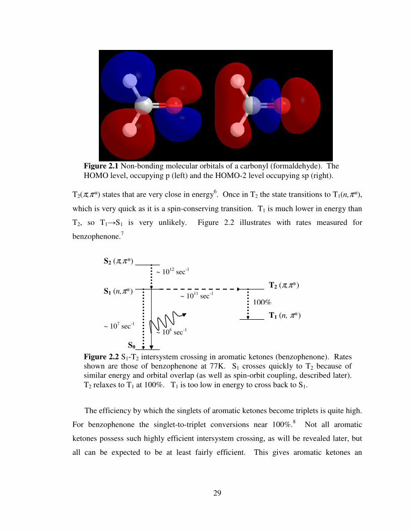
29
T2(π,π*) states that are very close in energy6. Once in T2 the state transitions to T1(n,π*),
which is very quick as it is a spin-conserving transition. T1 is much lower in energy than
T2, so T1→S1 is very unlikely. Figure 2.2 illustrates with rates measured for
benzophenone.7
The efficiency by which the singlets of aromatic ketones become triplets is quite high.
For benzophenone the singlet-to-triplet conversions near 100%.8 Not all aromatic
ketones possess such highly efficient intersystem crossing, as will be revealed later, but
all can be expected to be at least fairly efficient. This gives aromatic ketones an
Figure 2.1 Non-bonding molecular orbitals of a carbonyl (formaldehyde). The
HOMO level, occupying p (left) and the HOMO-2 level occupying sp (right).
S0
S1 (n,π*)
S2 (π,π*)
T1 (n, π*)
T2 (π,π*)
~ 106 sec
-1
~ 1011
sec-1
100%
~ 1012
sec-1
~ 107 sec
-1
Figure 2.2 S1-T2 intersystem crossing in aromatic ketones (benzophenone). Rates
shown are those of benzophenone at 77K. S1 crosses quickly to T2 because of
similar energy and orbital overlap (as well as spin-orbit coupling, described later).
T2 relaxes to T1 at 100%. T1 is too low in energy to cross back to S1.

30
advantage for organic phosphor design, they generate triplets readily, but in order to be
used in phosphor design these triplets must be allowed to emit.
2.3.2 Spin-Orbit Coupling
In order for triplets to relax emissively to the ground state, S0, a spin flip must again
take place. It is not incorrect to refer to the transition T1→S0 as intersystem crossing
since there it is a non-spin-conserving process. The most prevalent mechanism for spin
flipping in organic materials is a phenomenon known as spin-orbit coupling.9 Spin-orbit
coupling (also known as spin-orbit interaction or spin-orbit effect) occurs when the spin
of an electron is influenced by the electron’s motion about a nucleus. Though classical
physics is often a poor model for quantum mechanics one can think of electrons as
charged spinning particles orbiting around a nucleus. The angular movement of the
electron through the magnetic field created by the atomic nucleus can impart an
electromagnetic force on the electron causing it to change its spin. This can only occur if
the electron is alone in an orbital and thus free from the influences of another electron.
The Pauli exclusion principle is absolute.
Spin-orbit coupling is most prevalent in atoms whose nuclei are large.
Mathematically, the Hamiltonian for spin-orbit interaction is strongly proportional to the
nuclear charge, which is intractably proportional to the size of the atom.10
A simplified
version of this factor is given in equation 2.1.
���� = −��
�� ����� ∙ � (2.1)
There are two main components to this factor: the coefficient and the dot product. The
coefficient is a collection of constants (e is the elementary charge of an electron, ε0 is the
permittivity of the vacuum, me is the mass of an electron, and c is the speed of light) and
the atomic number of the acting nucleus, Z, to the fourth power. The magnitude of spin-
orbit coupling is thus greatly affected by the size/weight/charge of the nucleus. The
vector portion is the dot product of the electron’s angular momentum, l, and spin, s. This
demonstrates that spin-orbit coupling is critically reliant on the motion of the electron and
its spin in the field. Regardless of the nuclear size, non-interacting electron vectors and
nuclear fields (a zero dot product) would preclude any triplet formation in the system.

31
Conversely, Z will never be zero, so even if the l.s factor is small, spin-orbit coupling is
possible.
It is spin-orbit coupling that facilitates the intersystem crossing necessary for the
phosphorescence of all phosphors including organometallic. Because larger nuclei
exhibit both greater nuclear magnetic fields and excess orbital space for non-bonded
electrons this effect is more pronounced in heavy atoms such as transition metals and
large halogens. This, in part, explains why heavy metal organic phosphors like tris(2-
phenylpyridine)iridium (Ir(ppy)3) are phosphorescent while light metal chelates such as
Tris(8-hydroxyquinolinato)aluminium (Alq3) are predominantly fluorescent.
Though spin-orbit coupling is strongly proportional to the size of the nucleus
involved, it does occur, though not usually very efficiently, for lighter elements. The
triplets generated by aromatic ketones can accommodate intersystem crossing from T1 to
S0 because they exhibit a degree of spin-orbit coupling at the carbonyl oxygen. Rather
than drawing its greatest influence from the size of the oxygen atom, it is the orbital
arrangement around the carbonyl oxygen that provides favorable spin-orbit coupling.
This is what makes aromatic ketones rather unique among light-element organics. The
excited state triplet, π*, mixes weakly with the non-bonded ground state singlet, n, on the
cabonyl oxygen. Both orbitals are strongly localized at the oxygen atom, a factor that
makes spin-orbit coupling non-trivial as the electron changes energy around a single
nucleus. Thus it is spin-orbit coupling that allows aromatic ketones such as
benzophenone to exhibit a detectable, but modest amount of phosphorescence. With no
heavy nuclei involved, phosphorescence QY remain at fractions of a percent.
2.3.3 Vibrational Suppression
As discussed in section 2.1.2 internal conversion by vibrational modes is far faster,
and thus more competitive, than emissive triplet decay, phosphorescence. This is very
detrimental to the phosphorescence of aromatic ketones. Though they generate triplets
efficiently, they are very weak phosphors. To improve their brightness they are often
frozen into glassy solids such as non-crystalline solvents at low temperatures or other
rigid matrices. Like the Confined Aromatics described in Chapter 1 Section 1.4.3
removal of the vibrational modes prevents internal triplet conversion, which allows triplet
emission to dominate. Most studies of aromatic ketone phosphorescence are measured in

32
these conditions.11
Unfortunately though for device design, little-to-no phosphorescence
is generated in ambient, concentrated, or room temperature conditions.
2.3.4 Applied to DHAE
One very simple aromatic ketone is benzaldehyde. This molecule consists of a
benzene ring substituted by a single formyl group. Figure 2.3 shows this and other
pertinent aromatic ketones. Unlike other popular aromatic ketones, benzophenone and
acetophenone, benzaldehyde has no additional carbon substitution at the carbonyl making
the carbonyl more accessible to extra-molecular interactions. It is the smallest and
simples possible aromatic ketone and key to the discovery and earliest applications of the
DHAE principle.
DHAE relies on an intermolecular interaction at the carbonyl site of benzaldehyde,
which is why having as little carbonyl substitution possible is very favorable. Additional
groups attached nearby provide some steric hindrance to the species that may otherwise
come close enough to interact with the triplet-generating and spin-orbit active moiety, the
carbonyl. As is next explained, access to the carbonyl is critical to the DHAE principle.
If spin-orbit coupling is to be increased, a greater nuclear charge (Z) must be applied at
the carbonyl oxygen. This is why benzaldehydes are used throughout this work.
2.4 The Heavy Atom Effect
Though the ability of an excited state molecule to exhibit intersystem crossing is
generally an intrinsic property of its molecular orbitals and not particularly easy to alter
for a given molecule, a strategy to promote electron flipping does exist in the heavy atom
effect. Described here, the heavy atom effect is both a popular means to promote triplet
generation, induce spin-orbit coupling, and is an absolutely critical portion of the DHAE
design principle.
OO O
Figure 2.3 Benzaldehyde, acetophenone, and benzophenone (left-to-right).

33
2.4.1 Background
The heavy atom effect is defined by the International Union of Pure and Applied
Chemistry:
“The enhancement of the rate of a spin-forbidden process by the presence
of an atom of high atomic number, which is either part of, or external to,
the excited molecular entity. Mechanistically, it responds to a spin-orbit
coupling enhancement produced by a heavy atom.”12
The presence of a heavy atom helps to promote intersystem crossing by providing a
heavy/highly-charged nucleus to influence the excited electron (spin-orbit coupling)
while mixing its large, unfilled d orbitals with those of the excited molecule.13
It is
essentially adding a heavy atom to increase the factor Z from equation 2.1 while also
providing a possible improvement to the vector factor, l.s (this depends on how the heavy
atom is added to the system).
The heavy atom effect is very well established, but usually observed as a rather weak
phenomenon. Reports from as early as the 1950s demonstrate that chromophores in
iodinated solvents exhibit more triplet absorption (a rare, usually extremely weak S0 + hν
→ T1 transition) than when in light element solvents.14
Since then innumerable reports
utilizing the effect have been recorded often with organic phosphors being halogenated to
enhance their very modest phosphorescence to detectable levels.15,16,17
The effect,
though, is always definite but mild. Few numbers are given relating phosphorescent QYs
with and without the presence of heavy atoms (data is usually shown as relative spectral
intensities), presumably because the final effect is still a very weak signal and perhaps
prone to QY measurement errors. The QY enhancement may only be a few fold, which
is relatively significant, but unimpressive practically.
2.4.2 Internal and External Effects
Uses of the heavy atom effect generally fall into two classes: internal and external.
The internal effect refers to the covalent addition of a heavy atom, usually a large
halogen, to the molecular structure itself. Halogens are popular in this role as they are
easily substituted for hydrogen in chemical structures. The external effect is the addition
of heavy atoms, again usually halogens, to the environment of the chromophore in hope
of promoting triplet formation from mixing and collisional interactions. The first is more

34
elegant and effective, but requires alteration of the intended phosphor, which may not
always be feasible. The second is more versatile, but less effective in most cases.
DHAE uses both effects to achieve high efficiency phosphorescence. In practice the
heavy atom is usually bromine or iodine, two heavy atoms that can be easily added to
organic structures either for the internal effect or to solvent and other environmental
molecules for the external effect. In this report bromine is used almost exclusively as it
has proved to work very well, for reasons discussed later.
2.4.3 Applied to DHAE
The usual method for achieving the external heavy atom effect has been to add
iodinated or brominated molecules to the matrix surrounding the phosphorescent
chromophore.18
These are perhaps the simplest ways to introduce heavy atoms to the
sample, and they do work, but they are very indirect. They rely on collisional (in
solution) or resonant, solid-state (in glasses) interactions, which are random in the
typically used media, unordered systems of solutions and/or frozen glasses.
The DHAE principle uses a directed approach to attract the halogen to the
chromophore. As described in section 2.3, the critical part of the molecule for
phosphorescence is the carbonyl oxygen. It is at this nucleus that we have the intrinsic
mixing of triplet and singlet states that makes phosphorescence possible in benzaldehyde
and all aromatic ketones. If the heavy atom can interact specifically with that part of the
molecule, the heavy atom effect (promoting spin-orbit coupling) would be optimal for the
enhancement of phosphorescence. This is why having an accessible ketone is also
important. Figure 2.4 illustrates this situation, which is exactly what DHAE achieves.
Oriented in this way we later demonstrate how phosphorescent QYs can be increased
Br O
Figure 2.4 Bromine at an ideal position to exert the
heavy atom effect and promote spin-orbit coupling in
benzaldehyde.
2.7 – 3.3 Å

35
from ΦPh < 0.001 to ΦPh > 0.6 by employing this design. The means by which this
unique orientation is achieved is discussed next.
2.5 Halogen Bonding
Halogen bonding, despite being a fifty-year-old synthon in crystal design, is
beginning to receive a great deal of modern attention.19
It is halogen bonding that allows
the DHAE principle to direct the heavy atom to the phosphorescent chromophore in
benzaldehydes. Here are described the history, working principles, and identifications of
halogen bonding so that the reader can understand the evidence and analysis later in this
work.
2.5.1 Background
Discovered in 1954 by Odd Hassel (though evidence had been surfacing since the
mid nineteenth century) halogen bonding is a very close analog of hydrogen bonding.20
An electron deficient species is drawn to an electron rich nucleophile. The interaction is
non-covalent, but sufficiently strong to be a directing force in some crystals and semi-
ordered solid states. In his most notable work Hassel reported the crystal structure of a
1:1 cocrystal comprised of elemental bromine (Br2) and 1,4-dioxane. Figure 2.5 shows
this structure. The distances measured between the bromine atoms and the neighboring
oxygen atoms of the dioxane is 2.71 Å. The sum of the van der Waals radii of both
atoms (bromine and oxygen) is 3.35 Å. To observe nuclear distances so far below their
van der Waals distance means that clearly there is an attractive force operating between
the two. From this report the paradigm of halogen bonding was born, and this reported
distance of 2.71 Å remains among the closest, and therefore strongest, halogen bonds
cataloged.21
O O Br Br O O
2.71 Å
Figure 2.5 Cocrystal structure of bromine and 1,4-dioxane.

36
In more recent years halogen bonding has become a very popular directing force in
the emerging field of crystal engineering.22
Halogen bonds are being used to design
crystals for pharmaceutical and electronic applications.23,24,25
They are also being used in
semi-crystalline liquid crystals for display and electronic technologies and scaffolds for
solid state polymerization.26,27,28
The paradigm is also making its way into non-
pharmaceutical biomedical research where halogenated nucleic acids provide unique
interactions.29
Halogen bonding is experiencing rapid growth, fully in parallel to that of
crystal engineering.
2.5.2 Electron-deficient Halogens
At first halogen bonding seems counterintuitive as halogens are highly
electronegative atoms. One may wonder how halogens can behave as electrophiles. The
answer lies in their bonding. Bound halogens are sharing electrons with their partner
atoms, which draws electron density away from the halogen at the end opposite the bond.
This is most pronounced for larger halogens, bromine and iodide. Figure 2.6 is
reproduced from Ho and coworkers and shows this trend as demonstrated by ab inito
calculations.30
Figure 2.6 Calculated electrostatic potential surfaces of bound halogens. Larger
halogens (moving right) and those bound to more electron-withdrawing partners
(lower row) exhibit greater partial positive character, far more positive even than
hydrogen or methyl (right most). Image is from Ho and coworkers.

37
Figure 2.6 also shows an important trend that halogens bound to electron accepting
groups display a greater positive, and thus electrophilic, character. This allows bound
halogens bromine and iodine to be attracted to electron rich nucleophiles. In literature
oxygen and nitrogen are the usual nucleophiles as they have lone-pair electrons readily
available for donation to this bond.
The arrangement is directly analogous to hydrogen bonding, an electron deficient
atom is attracted to an electron rich nucleophile, but halogen bond has two important
differences. First, halogen bonds are measured stronger than hydrogen bonds. Second,
and possibly more importantly, halogen bonds are much more directional. Hydrogen
atoms are wholly electropositive. Halogen bonds, conversely, have only a very select
area of electopositivity and it is strongly related to the direction of their covalent bond.
Thus halogen bonds are much better suited to crystal design and directed interactions.
Aside from these two aspects, halogen bonding is a nearly direct analog of hydrogen
bonding and all general governing properties applied to each.
2.5.3 Distances and Angles
Because halogen bonding is a much more narrowly accepting interaction, the window
of electro-positivity is quite narrow, there are characteristic distances and angles
associated with it. Focusing on Br..O halogen bonds, nuclear distances tend to be
anywhere from 3.0 – 3.3 Å. Though distances below 3.0 Å (Hassel’s 2.71 Å, for
example) have been reported, they remain in the minority. Any measured Br..O distance
below 3.35 Å is considered evidence of a halogen bond. The distance of the bond is
correlated to its strength. The shorter the Br..O distance, the stronger the bond and the
more interaction (sharing of orbitals) exists between the two atoms’ electrons.
Halogen bonds also exhibit a two characteristic angles. Figure 2.7 shows the angles
common to all halogen bonds as well as the distances common to Br..O halogen bonds.
Because the region of electropositivity is directly opposite the covalent bond the angle
between R-X..O is always nearly 180
o.30
The electrons of the nucleophile (oxygen in this
report) are typically sp2 or sp
3 hybridized and the interaction between them and the
halogen follow this orientation. Thus the angles between R’-O..X are usually close to
120oC, though they exhibit more variance than the 180
o R-X
..O angle.
30 Though the
oxygen of a ketone does not have its lone pair electrons in sp2 orbitals (section 2.3.1) the
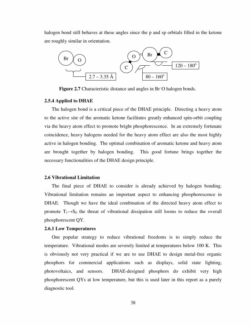
38
halogen bond still behaves at these angles since the p and sp orbitals filled in the ketone
are roughly similar in orientation.
2.5.4 Applied to DHAE
The halogen bond is a critical piece of the DHAE principle. Directing a heavy atom
to the active site of the aromatic ketone facilitates greatly enhanced spin-orbit coupling
via the heavy atom effect to promote bright phosphorescence. In an extremely fortunate
coincidence, heavy halogens needed for the heavy atom effect are also the most highly
active in halogen bonding. The optimal combination of aromatic ketone and heavy atom
are brought together by halogen bonding. This good fortune brings together the
necessary functionalities of the DHAE design principle.
2.6 Vibrational Limitation
The final piece of DHAE to consider is already achieved by halogen bonding.
Vibrational limitation remains an important aspect to enhancing phosphorescence in
DHAE. Though we have the ideal combination of the directed heavy atom effect to
promote T1→S0 the threat of vibrational dissipation still looms to reduce the overall
phosphorescent QY.
2.6.1 Low Temperatures
One popular strategy to reduce vibrational freedoms is to simply reduce the
temperature. Vibrational modes are severely limited at temperatures below 100 K. This
is obviously not very practical if we are to use DHAE to design metal-free organic
phosphors for commercial applications such as displays, solid state lighting,
photovoltaics, and sensors. DHAE-designed phosphors do exhibit very high
phosphorescent QYs at low temperature, but this is used later in this report as a purely
diagnostic tool.
C
O Br
80 – 160o
C
120 – 180o
Figure 2.7 Characteristic distance and angles in Br..O halogen bonds.
Br O
2.7 – 3.35 Å

39
2.6.2 Polymer/Crystal Embedding
Another strategy is to reduce vibration via the use of a rigid matrix such as a glassy
polymer. These methods are more practical than low temperatures, but they are not as
effective for a variety of reasons. Even highly rigid, glassy polymers exhibit some degree
of vibrational freedom at ambient temperatures and any restriction to vibrational
dissipation of the phosphor is strictly external. Polymer embedding is also complicated
by the effectiveness of the mixing. Being that the overarching benefit to the DHAE
principle is the promise of limitless metal-free organic phosphor design, getting large or
complex organic molecules to mix well with polymers can become a great challenge.
That, combined with marginal effectiveness makes this approach suboptimal. DHAE-
designed phosphors can be enhanced by polymer matrices, as will be demonstrated in
Chapter 9, but not to the greatest effect.
Doping organic phosphors into crystals is an approach with mixed success. As
mentioned in chapter 1, dye inclusion crystals attempt to confine phosphorescent
chromophores into rigid ionic or small molecule crystals in a purely interstitial
paradigm.31
This approach suffers from difficulties in mixing as what is essentially
doping organic phosphor molecules into small and dissimilar crystals is a very inefficient
process. The use of crystals, however, is not without promise. If both host and dopant
are designed to cocrystallize efficiently, the net effect can provide a rigid, vibration-free
environment for the phosphor where mixing is far more efficient than in ionic or greatly
dissimilar structured crystals. It is in this careful design that the desired aspects of the
DHAE principle are brought together and aided by their crystal packing.
2.6.3 Applied in DHAE
By now the critical aspects of the DHAE design principle have been given: halogen
bonding directs a heavy atom to interact with the triplet-generating carbonyl in an
aromatic ketone. The final important facet of DHAE to understand is the added benefit
of the halogen bond in the suppression of vibrational dissipation. When crystallized the
halogen bond helps to pack the two moieties very tightly, provided that the halogen bond
is reasonably strong. The excited state molecular orbitals of the aromatic ketone are very
localized at the carbonyl, which means that the vibrational modes are as well. Having a
strong halogen bond nearby means that the carbonyl is essentially pinned down by a very

40
large neighbor. This prevents vibrational freedom of the excited state and removes the
internal conversion pathway to triplet relaxation. This must all be achieved in the crystal
state, however, which is a caveat that can make proper design of a DHAE phosphor
challenging.
2.7 Conclusions
The DHAE design principle uses solid state halogen bonding to direct the heavy atom
effect to the triplet-generating carbonyl site of an aromatic ketone. This technique
efficiently combats the two biggest challenges to organic phosphorescence. First, the
heavy atom, sharing orbital space with the carbonyl oxygen thanks to the electrostatic
interaction of the halogen bond, provides enhanced spin-orbit coupling to promote not
only S1 → T1 (technically, S1 → T2 in aromatic ketones) but T1 → S0 as well. Second,
the fact that this takes place in a highly ordered crystalline state with the halogen bond
closely confining the carbonyl and halogen eliminates many vibrational freedoms at the
carbonyl, which reduces non-emissive loss of the triplets. The halogen bonding motif
utilized also allows for crystal design, much as is becoming popular in the contemporary
field of crystal engineering. The DHAE design principle can be used in conjunction with
crystal engineering to design metal-free organic chromophores that contain aromatic
ketones and halogens that bond to create bright phosphorescence.

41
2.8 References
1 A. Kohler, J.S. Wilson, and R.H. Friend Adv. Mater. 2002, 14, 701.
2 Turro, N.J. Modern Molecular Photochemistry (University Science Books, Sausalito
CA, 1991). 3 O. Bolton, K. Lee, H.-J. Kim, K.Y. Lin, and J. Kim Nature submitted.
4 J. Ferguson and H.J. Tinson J. Chem. Soc. 1952, 3083.
5 E.W. Abrahamson, J.G.F. Littler, and K.-P. Vo J. Chem Phys. 1966, 44, 4082.
6 M. Kiritani, T. Yoshii, N. Hirota, and M. Baba J. Chem. Phys. 1994, 98, 11265.
7 E.H. Gilmore, G.E. Gibson, and D.S. McClure J. Chem. Phys. 1952, 20, 829;
correction, ibid., 1955, 23, 399. 8 T. Itoh Chem. Phys. Lett. 1988, 151, 166.
9 M. Koyanagi and L. Goodman Chem. Phys. Lett 1971, 9, 636.
10 P.W. Atkins, and R.S. Friedman Molecular Quantum Mechanics (Oxford University
Press, New York, NY, 1997). 11
A.M. Turek, G. Krishnamoorthy, K. Phipps, and J. Saltiel J. Phys. Chem. A, 2002, 106,
6044. 12
IUPAC Compendium of Chemical Terminology, 1996, 68, 2245. 13
G.G. Giachino and D.R. Kearns J. Chem. Phys. 1970, 52, 2964. 14
M. Kasha J. Chem. Phys. 1952, 20, 71. 15
M.R. Wright, R.P. Frosch, and G.W. Robinson J. Chem. Phys. 1960, 33, 934. 16
A. A. Avdeenko, O. S. Pyshkin, V. V. Eremenko, M. A. Strzhemechny, L. M.
Buravtseva, and R. V. Romashkin Low Temp. Phys. 2006, 32, 1028. 17
Y. Zeng, L. Biczok, and H. Linschitz J. Phys. Chem. 1992, 96, 5237. 18
S.P. McGlynn, M. Kasha, and T. Azumi J. Chem. Phys. 1964, 40, 507. 19
S.K. Ritter Chemical & Engineering News 2009, 87, 39. 20
O. Hassel Nobel Lecture June 9, 1970. 21
P. Metrangolo and G. Resnati, G. Chem. Eur. J. 2001, 7, 2511. 22
P. Metrangolo, F. Meyer, T. Pilati, G. Resanti, and G. Terraneo Angew. Chem.-Intl. Ed.
2008, 47, 6114. 23
X.Y. Lu, T. Shi, Y. Wang, H.Y. Yang, X.H. Yan, X.M. Luo, H.L. Jiang, and W.L. Zhu
J. Med. Chem. 2009, 52, 2854. 24
A.R. Voth and P.S. Ho Curr. Topics in Med. Chem. 2007, 7, 1336. 25
H.M. Yamamoto, Y. Kosaka, R. Maeda, J. Yamaura, A. Nakao, T. Nakamura, and R.
Kato ACS Nano 2008, 2, 143. 26
H. L. Nguyen, P. N. Horton, M. B. Hursthouse, A. C. Legon, and D. W. Bruce, J. Am.
Chem. Soc. 2004, 126, 16. 27
P. Metrangolo, C. Präsang, G. Resnati, R. Liantonio, A. C. Whitwood, and D. W.
Bruce, Chem. Commun. 2006, 3290. 28
A. Sun, J.W. Lauher, and N.S. Goroff Science 2006, 312, 1030. 29
A.R. Voth, F.A. Hays, and P.S. Ho PNAS 2007, 104, 6188. 30
Auffinger, P., Hays, F.A., Westhof, E., and Ho, P.S. Proc. Natl. Acad. Sci. 2004, 48,
16789. 31
B. Kahr and R.W. Gurney Chem. Rev. 2001, 101, 893.

42
Chapter 3
The Directed Heavy Atom Effect at Work in Substituted Benzaldehydes
Now that the details of the DHAE design principle are clear, this chapter
demonstrates its application via the molecule 2,5-dihexyloxy-4-bromobenzaldehyde
(Br6A). This compound exhibits the properties required for DHAE to succeed. It is an
aromatic ketone, a substituted benzaldehyde, and its crystals exhibit strong halogen
bonding. By being halogenated Br6A molecules have not only the added benefit of an
internal heavy atom effect, but also can halogen bond among themselves in the solid state
to further enhance spin-orbit coupling at the carbonyl. This allows Br6A to form bright
phosphorescent crystals. In this chapter we present this compound in specific exploring
its photophysical and solid-state properties.

43
3.1 Introduction
The ultimate goal of the DHAE principle is to give researchers the freedom to design
metal-free organic phosphors that are easy to synthesize and purify, are stable for device
applications, and are practically bright.
3.2 Results and Discussion
2,5-dihexyloxy-4-bromobenzaldehyde (Br6A) is a simple, non-conjugated organic
compound easy to synthesize in large quantities by a variety of synthetic routes.1 Figure
3.1 shows the chemical structure of Br6A. The compound is a substituted benzaldehyde
with a bromine atom para to the ketone and alkoxy substituents elsewhere on the
aromatic ring. In order to ensure that no optical observations were the result of
impurities, metallic or otherwise, batches of Br6A were purified stringently as described
in section 3.3.2. Br6A exhibits very interesting photophysical properties based on its
environment and state.
3.2.1 Crystal Structure
The DHAE requires that the aromatic ketone exhibit halogen bonding. This can only
be determined by single crystal x-ray diffraction (XRD). Br6A is a crystalline solid at
room temperatures. Large crystals (dimensions over 1 mm) can be grown from a slowly
evaporated methanol solution. Crystals were grown in this manner and submitted for
single crystal XRD to Dr. Jeff W. Kampf in the department of chemistry, University of
Michigan. Figure 3.2 shows the crystal structure of Br6A.
Evidence that there is a strong halogen bond active in crystals of Br6A exists in the
close nuclear distances between the bromine and oxygen atoms. This distance measures
2.86 Å, which is among the shortest, and therefore strongest, halogen bonds reported.2
The angle measured between C=O..Br is 126
o and that of O
..Br-C is 180
o, which are also
consistent with literature. From this we see that not only is halogen bonding present and
directed to the carbonyl oxygen, as is optimal, but also that the halogen bond is
particularly strong. This is important as it means also that the tight crystal may have
O O
Br
O
Figure 3.1 Chemical structure of Br6A.

44
greatly reduced vibrational freedom at the carbonyl. From this we can see that the
halogen bond is successful. Thus the structural goals of the DHAE design principle are
working, an aromatic ketone is halogen bonding to put a heavy atom extremely close to
the carbonyl oxygen. Excited state activity must next be examined using optical analyses
to determine if the DHAE is working.
3.2.2 Photophysical Properties: Solution
Because Br6A is among a family of popular aromatic ketones that have been studied
for decades, we can assume a great deal about its excited states. By comparing it to
benzophenone, for instance, we see that the transitions are well studied.3 First, the lowest
unoccupied molecular orbital represents the transition from non-bonding to π*, S1(n,π*).
However, the absorption transition from S0 to S1 is not allowed because the orbitals do
not overlap. S2 is the π-π* transition, which is allowed. T2 is the triplet state π-π*
transition and T1 is n-π*. Figure 3.3 illustrates this situation with hypothesized chemical
structures.4 Thus, the lowest energy absorption we would expect to see is actually
S0→S2, and not S0→S1, which is more common among organic compounds.
Figure 3.2 Crystal structure of Br6A.
2.86 Å

45
Br6A has a wide range of solubility, dissolving very well in non-polar solvents such
as hexanes as well as modestly in alcohols such as methanol. In solution the UV
absorption, photoluminescent (PL) excitation and PL emission of Br6A give us clear
insight into its excited state. Figure 3.4 shows the solution state photophysical properties
of Br6A.
As shown the UV-absorption spectrum of Br6A in methanol solution exhibits three
distinct peaks at λmax
= 230 nm, 265 nm, and 350 nm. These are presumably the
corresponding S0→S4, S0→S3, and S0→S2 transitions, respectively (remember that
S0→S1 is forbidden so it does not exhibit an absorption band). Kasha’s rule states that
for most, if not all, chromophores fluorescence is only derived from S1 and
phosphorescence only from T1.5 Thus we can disregard the S0→S4 transition (wholly)
and S0→S3 (mostly) for the purposes of this analysis. The S0→S2 transition, however, is
important in our analysis of the Br6A excited state. It represents the transition from π to
π* (anti-bonded) and is the primary excitation route to all Br6A emission.
S0
+hν
-hν O
Br
RO
OR
O
Br
RO
OR
O
Br
RO
OR
O
Br
RO
OR
O
Br
RO
OR
S1
S2
T1
T2
Figure 3.3 Hypothesized energy diagram of Br6A. (Gaps are not drawn to scale.)
Following the event arrows: (S0) in the ground state Br6A rests in its lowest energy
resonance structure. (S2) The π-π* transition takes S0 directly into S2 because of the
orbital overlap in the aromatic ring. (S1) However, a lower-energy singlet exists
when the negative charge is at the oxygen atom. S2 quickly relaxes to S1. (T2)
orbital overlap and a small energy barrier promote intersystem crossing between S1
and T2. (T1) The radical is stabilized by the higher substitution in a quinoid
orientation.4 T2 quickly relaxes to T1, which can emit if it survives long enough.

46
Solutions of Br6A exhibit fluorescent emission whose QY and emission spectrum are
variable with the solvent used. As shown in Figure 3.4 chloroform solutions of Br6A
emit with a λmax
= 425 nm. Solutions in methanol emit at λmax
= 460 nm, significantly
red-shifted from chloroform. In both cases the solution is excited with 365 nm light.
This shift is apparent in polar, protic solvents such as alcohols and water (used as a co-
solvent, Br6A is insoluble in pure water). This is presumably due to hydrogen bonding
acting on the carbonyl oxygen and is not seen from polar aprotic solvents such as
acetonitrile and acetone.
As explained in Chapter 2, the excited state of aromatic ketones is localized at the
carbonyl, thus interactions like hydrogen bonding acting at that site greatly affect the
emission and excited state activity. Chloroform solutions exhibit PL QYs of ΦFl =
0.005 with quantum lifetimes measured at τ = 0.5 ns. Methanol solutions exhibit ΦFl =
0.128 with longer lifetimes of τ = 2.4 ns. If we use equation 1.3 we see that the
fluorescent rates, the rates at which the S1→S0 + hν transition take place, are kFlCHCl3
= 10
MHz and kFlMeOH
= 53 MHz. Fluorescence from methanol solution is over five-times
faster than that from chloroform solution. Longer wavelength emission from methanol
solution indicates that the hydrogen bonding stabilizes the S1 state, which lowers its
200 250 300 350 400 450 500 550
Absorp
tion (
a.u
., n
orm
.)
Wavelength (nm)
Inte
nsity
(a.u
., norm
.)
Figure 3.4 UV-Absorption, PL emission, and PL excitation of Br6A in
chloroform and methanol solutions. UV-Abs in methanol (solid), emission in
chloroform (short dash), emission in methanol (long dash), excitation in
chloroform (dotted). (Excitation in methanol is identical to that in chloroform.)

47
energy and thus the bandgap. This lowering of energy presumably puts S1 somewhat
below T1, reducing intersystem crossing and raising ΦFl as compared to chloroform.
Figure 3.4 shows the PL excitation of Br6A in chloroform solution. Excitation in
methanol solution is identical, which indicates that the solvent interaction is with the
excited state, not the ground state. The longer wavelength excitation band fits well into
the 350 nm absorption band indicating that fluorescent emission is derived from all
vibrational modes of that transition. Notice also a small portion of the absorption band at
265 nm is included in the excitation spectrum. This is interesting as it indicates that only
the lower energy portion of the vibrational states of S3 may lead to emission from S1.
Conversely, it appears that all modes of S2 may relax to S1 and emit because the shape
and position of the excitation matches well to the S0→S2 absorption. As Sn→S1
transitions are assumed to be very fast (~10-12
sec)6 and once relaxed to S1 the electron
has no memory of its route and is no different than those excited directly to S1, we must
assume that the states of S3 that do not excite fluorescent emission must lead to another
end. These high-energy absorptions may lead to reaction or decomposition of the
chromophore.
3.2.3 Photophysical Properties: Crystals
Crystalline Br6A exhibits bright green phosphorescence. Figure 3.5 shows typical
crystals as well as a sampling of PL emissions. Because the DHAE principle only works
when the chromophore is in perfect order, its crystal, samples of poor crystallinity do not
emit strong phosphorescence. In Figure 3.5 three spectra are given representing samples
of varying crystal quality. One is taken from a sample grown from a dropcast of a
chloroform solution. These produce extremely fast-grown crystals of very poor quality,
taking only seconds to form. As such the emission spectrum shows dominant
fluorescence with a λmax
= 420 nm and only a soft shoulder in the phosphorescent region
around 500-530 nm. A second sample is grown from a methanol recrystallization at
-12oC, which allows for slightly slower-growing crystals and, thus, more highly
crystalline samples. These crystals grew over the course of minutes. This sample
produces a fairly even mix of fluorescence and a now clear peak of phosphorescence at
λmax
= 500-530 nm. The last sample is grown from methanol recrystallization at room

48
temperature. These crystals are grown over the course of 24 hours and are the highest
quality crystals in this study. As such, they show dominant phosphorescence with minor
fluorescence. This clearly demonstrates the importance of high order in the DHAE
principle. Attempts were made to quantify crystal quality by enthalpy using differential
scanning calorimetry. A slight trend was seen, but high error rendered the results
inconclusive.
There are two ways by which we can know that this green emission is
phosphorescence. Firstly, it is red-shifted from the blue fluorescence. We know that the
blue fluorescence is the S1→S0 +hν transition (Kasha’s rule). By definition there can be
no lower singlet state. Only a triplet or intermolecular species could exist at a lower
energy. To rule out intermolecular interaction we freeze a toluene solution of Br6A in
liquid nitrogen at 77K, making a frozen glass. In this condition there can be no
intermolecular interaction as the chromophore is diluted to an optical density of 0.1 (ca.
0.85 µM). There is also greatly reduced vibrational dissipation of T1 so we can see
exactly what energy T1 is at by the observed phosphorescent emission. As Figure 3.6
shows, emission from Br6A in glassy toluene solution at 77K is identical to the green
portion of the emission from room temperature crystals. Thus we can conclude that both
emissions are phosphorescence from T1.
400 450 500 550 600
Inte
nsity
(a.u
.)
W avelength (nm)
Figure 3.5 Photo and PL emission spectra of solid state Br6A in various crystal qualities.
Dropcasts (dotted), fast recrystallization (dashed), and slow recrystallization (solid).
Crystals shown in photo are all grown from slow recrystallization.

49
The other determining measurable is quantum lifetime. A dropcast sample of Br6A
was measured on a strobe laser system. A pulsed laser excites the sample and a strobic
detector measures the emission intensity as a function of time. Figure 3.7 shows the
decay curve as measured. Remembering equation 1.2 we can fit the curve (at least the
long-lived portion) to an exponential decay to solve for a reasonable quantum lifetime, τ.
Fluorescent lifetimes are typically in the pico-to-nanosecond range so detecting anything
longer points strongly to phosphorescence. As shown these samples measured 5.4
milliseconds, which is several orders of magnitude slower than fluorescence. From this,
clearly, the green emission is phosphorescence. (The spectral differences rule out any
possible delayed fluorescence.)
Finally we examined the QY of these crystals to understand how efficiently our
triplets are emitting. In solution and any non-crystalline state the phosphorescent
quantum yield, ΦPh, is practically zero as no phosphorescent emission is detected. We
cannot, therefore, make a measurement of the improvement of ΦPh due to the DHAE
principle. As discussed the phosphorescent emission strength is closely tied to the crystal
quality. High quality crystals (slowly dropcast from methanol solution at room
temperature) were measured using an integrating sphere to exhibit QY of ΦPh = 0.029
(2.9%). Not outstandingly high, but a marked improvement from zero. Lower quality
400 450 500 550 600 650
Inte
nsity (
a.u
., n
orm
.)
Wavelength (nm)
Figure 3.6 PL emission of Br6A in glassy toluene at 77K.
The sample was excited with 360 nm light.

50
crystal samples (dropcasts) measured much lower, typically in the range of ΦPh = 0.001-
0.01 (0.1-1%).
3.3 Experimental
3.3.1 General Methods
All chemicals used were purchased from Sigma Aldrich and used without further
purification. Deuterated solvents for NMR were purchased from Cambridge Isotope
Laboratories. Proton NMR was conducted on a Varian Inova 500 using CDCl3 solvent
with chemical shifts identified relative to 0.05 v/v% tetramethylsilane standard (0.00
ppm). Anhydrous tetrahydrofuran was generated by refluxing over sodium metal and
benzophenone collected only from deep purple solution.
UV Absorption measurements were collected using a Varian Cary 50 Bio
spectrometer with solution state samples held in a quartz cuvette. PL emission,
excitation, and quantum yield data were collected using a Photon Technologies
International (PTI) Quantamaster system equipped with an integrating sphere. Quantum
lifetime data was collected using a PTI LaserStrobe. Quantum lifetime calculations were
carried out on the FeliX32 software partnered with the PTI equipment. XRD was
conducted using a Bruker SMART APEX CCD-based X-ray diffractometer as described
below.
0 5000 10000 15000 20000
MeasuredCalculated
Inte
nsity (
a.u
.)
Time (µs)
τ = 5.4 ms (5400 µs)
Figure 3.7 Phosphorescent lifetime measurement of Br6A crystals.

51
3.3.2 Synthesis and Characterization
Synthesis of 2,5-dihexyloxy-1,4-dibromobenzene (Br6). 2,5-dibromohydroquinone (1
equiv.) and 1-bromohexane (2.5 equiv.) is loaded into a two-neck round bottomed glass
flask and dissolved into dimethylformamide (ca. 1 ml solvent / g dibromohydroquinone).
Potassium carbonate (3 equiv.) is added and the flask is sealed under nitrogen, stirred,
and heated to 75oC for 24 hours. The reaction is then cooled, filtered, and rotovaped at
high temperature to remove all solvents. The product is purified by column
chromatography with hexanes. White crystals were collected at yields of 70-80%. For
Br6, 1H NMR (500 MHz, CDCl3): δ 7.05 (s 2H), 3.91 (t 4H), 1.76 (m 4H), 1.43 (m 4H),
1.33 (m 8H), 0.91 (m 6H).
Synthesis of 2,5-dihexyloxy-4-bromobenzaldehyde (Br6A). 2,5-dihexyloxy-1,4-
dibromobenzene (Br6, 1 equiv.) is loaded into a two-neck round bottomed glass flask and
vacuum purged with argon three times. Anhydrous tetrahydrofuran is added by syringe
(ca. 25 ml solvent / g Br6) and the vessel is placed into a bath of dry ice and 2-propanol
(-78oC). n-Butyllithium (1 equiv.) is added dropwise via syringe and the reaction is
stirred at -78oC for 1 hour. Anhydrous DMF (4 equiv.) is then added and the reaction is
allowed to warm to 23oC over three hours. The reaction is quenched carefully with water
and extracted with diethylether. The organic layer is collected and dried over MgSO4
before being filtered and rotovaped to remove solvents. Purification is done by column
chromatography with ethylacetate:hexane (1:30) eluent followed by successive
recrystallizations from methanol and acetonitrile at 23oC. White crystals were collected
at yields of 50-70%. For Br6A, 1H NMR (500 MHz, d6-DMSO): δ 10.29 (s 1H), 7.53 (s
1H), 7.23 (s 1H), 4.09 (t 2H), 4.01 (t 2h), 1.73 (m 4H), 1.42 (m 4H), 1.30 (m 8H), 0.87
(m 6H).
HO OH
Br
Br
BrC6H13
K2CO3
DMF, 75oC,
24 h
C6H13O OC6H13
Br
Br
1. 1x nBuLi /
THF, -78oC
2. DMF, 23oC C6H13O OC6H13
CHO
BrBr6 Br6A
Scheme 3.1 Synthetic Route to Br6A.

52
Crystal Structure of Br6A. The following analysis was conducted and report written by
University of Michigan Department of Chemistry staff crystallographer Dr. Jeff W.
Kampf as a paid service. Colorless blocks Br6A were grown by slow evaporation of a
methanol solution at 25 deg. C. A wedge-shaped crystal of dimensions 0.27 x 0.22 x
0.15 mm was cut from a larger mass and mounted on a Bruker SMART APEX CCD-
based X-ray diffractometer equipped with a low temperature device and fine focus Mo-
target X-ray tube (λ = 0.71073 A) operated at 1500 W power (50 kV, 30 mA). The X-ray
intensities were measured at 85(1) K; the detector was placed at a distance 5.055 cm from
the crystal. A total of 4095 frames were collected with a scan width of 0.5° in ω and
0.45° in phi with an exposure time of 15 s/frame. The integration of the data yielded a
total of 33365 reflections to a maximum 2θ value of 56.72° of which 4669 were
independent and 4444 were greater than 2σ(I). The final cell constants (Table 3.1) were
based on the xyz centroids of 9960 reflections above 10σ(I). Analysis of the data showed
negligible decay during data collection; the data were processed with SADABS and
corrected for absorption. The structure was solved and refined with the Bruker
SHELXTL (version 6.12) software package, using the space group P1bar with Z = 2 for
the formula C19H29O3Br. All non-hydrogen atoms were refined anisotropically with the
hydrogen atoms placed in idealized positions. Full matrix least-squares refinement based
on F2 converged at R1 = 0.0225 and wR2 = 0.0606 [based on I > 2sigma(I)], R1 = 0.0241
and wR2 = 0.0615 for all data.
• Sheldrick, G.M. SADABS, v. 2007/4. Program for Empirical Absorption Correction
of Area Detector Data, University of Gottingen: Gottingen, Germany, 2007.
• Sheldrick, G.M. SHELXTL, v. 6.12; Bruker Analytical X-ray, Madison, WI, 2001.
• Sheldrick, G.M. CELL_NOW, Program for Indexing Twins and Other Problem
Crystals, University of Gottingen: Gottingen, Germany, 2003.
• Sheldrick, G.M. TWINABS, v. 1.05. Program for Empirical Absorption Correction
of Area Detector Data, University of Gottingen: Gottingen, Germany, 2005.
• Saint Plus, v. 7.34, Bruker Analytical X-ray, Madison, WI, 2006.

53
Name Br6
Formula C19H29BrO3
Space Group P-1
Cell Lengths a 9.5083(8) b 9.6863(8) c 10.9481(9)
Cell Angles αααα 68.5630(10) ββββ 85.8470(10) γγγγ 84.9170(10)
Cell Volume 934.004
Z, Z’ Z: 2 Z’: 0
R-Factor (%) 2.25
3.4 Conclusions
The DHAE principle works in Br6A. This simple substituted, halogenated
benzaldehyde exhibits strong halogen bonding in its crystalline solid. This halogen
bonding brings the bromine atom of one molecule very close to the carbonyl oxygen of
its neighbor showing an interatomic spacing that indicates a non-covalent electronic
interaction. In solution, Br6A is fluorescent blue and exhibits solvatochromic properties
with protic solvents. Fluorescent quantum yields in solution are between 0.5 and 12%
indicating that singlet-to-triplet intersystem crossing is intrinsically quite efficient and
highly competitive with emissive singlet decay (fluorescence).
Once crystalline, Br6A exhibits green phosphorescence whose brightness is
correlated to the quality of the crystal. Well-ordered crystals exhibit strong
phosphorescence that is noticeably dominant over fluorescent emission with
phosphorescent quantum yields measured as high as 2.9 %. Quantum lifetimes of these
crystals are measured to be in the millisecond regime, clearly indicating emission from a
long-lived triplet state. Low temperature emission of Br6A in glassy toluene solution
agrees with room temperature crystals to remove the possibility that the green emission is
the result of a long-lived intermolecular phenomenon.
Here we demonstrate the DHAE design principle succeeding to active phosphorescent
emission from a room temperature, nonmetallic organic compound. Br6A is non-
phosphorescent at room temperatures unless it is crystallized to exhibit strong halogen
bonding. Phosphorescent quantum yields are good, immeasurably better than otherwise,
but still, frankly, far from competitive with established organometallic phosphors.
Table 3.1 Crystallographic Data for Br6A.

54
3.5 References
1 O. Bolton, K. Lee, H.-J. Kim, K.Y. Lin, and J. Kim Nature submitted
2 P. Auffinger, F.A. Hays, E. Westhof, and P.S. Ho Proc. Natl. Acad. Sci. 2004, 48,
16789. 3 E.H. Gilmore, G.E. Gibson, and D.S. McClure J. Chem. Phys. 1952, 20, 829;
correction, ibid., 1955, 23, 399. 4 The idea that the structure of T1 is a quinoidal diradical comes from computations done
in the following reference: S.T. Park, J.S. Feenstra, and A.H. Zewail J. Chem. Phys.
2006, 124, 174707. 5 M. Kasha Disc. Faraday Soc. 1950, 9, 14.
6 Turro, N.J. Modern Molecular Photochemistry (University Science Books, Sausalito
CA, 1991).

55
Chapter 4
Cocrystallization for Enhanced Brightness from DHAE
In order to enhance the QY of Br6A crystals a cocrystallization motif can be
employed. By diluting the Br6A chromophore into an optically inert “host” crystal we
can remove the possibility of triplet-triplet annihilation and excimer formation. The
caveat is that the host crystal must exhibit the same halogen bonding of Br6A. This is
critical to efficient emission. Here we present a simple addition to the DHAE design
principle to build suitable host compounds. By replacing the aldehyde moiety of Br6A
(or many other aromatic aldehydes, as is demonstrated in Chapter 5) with a bromine atom
an optically inert material suitable for cocrystallization is made. For Br6A this host is
1,4-dibromo-2,5-dihexyloxybenzene (Br6). When cocrystallized with Br6A, QYs of
Br6A solids can be increased from a modest 2.9% to a robust 68%. By utilizing
cocrystallization DHAE organic phosphors can achieve QYs competitive with
organometallics though, as is discussed here, cocrystallization can be complex and
achieving optimal QY requires some precision.

56
4.1 Introduction
In Chapter 3 the DHAE principle was demonstrated, working in high quality crystals
of pure Br6A. Though this finding is quite significant for designing nonmetallic
phosphors and holds great promise for new classes of material, QYs of 2.9% are far from
sufficient if these are to compete with organometallic phosphors. There are two most
probable reasons for the low QYs in these crystals, and both are derived from saturation
of the chromophore. Two well-known quenching mechanisms are triplet-triplet
annihilation and excimer formation. Triplet-triplet annihilation occurs when two triplets,
usually two neighboring triplet excited state molecules, interact to relax each other non-
emissively (though this occasionally leads to repopulation of higher energy singlet states
which may then emit fluorescence).1 Excimer formation occurs when the excited state of
one molecule interacts with a ground state neighbor to dimerize and reduce the overall
system energy. Triplet excimers are notoriously quenching because triplets are normally
fairly low in energy, making their excimers more so.2,3
Both of these mechanisms are
intermolecular. Crystals of pure Br6A represent the most concentrated state possible of
the chromophore, making these mechanisms very favorable. The probability of
chromophore-chromophore interaction is unity.
Just as for known organic phosphors (organometallics included) dilution of the
chromophore is critical to achieve high QY emission. By diluting the chromophore
intermolecular interactions are prevented, allowing triplets to emit rather than die from
triplet-triplet annihilation or relax vibrationally by triplet excimer formation. Prior to our
report of the DHAE principle, chromophore order was not sought in phosphors. In
PhOLEDs organometallic chromophores are diluted into host materials by carefully
controlled vapor deposition. The phosphor is randomly oriented (or at least their order is
not controlled). In existing studies of nonmetallic phosphors, samples are typically
chromophores liberally diluted into glassy solutions, unordered by definition. DHAE,
however, uses careful controlled order to greatly outpace these mixed state phosphors in
brightness. So successfully diluting a DHAE phosphor must be done in a similar but
optically inert crystal, one that exhibits the same halogen bonding character but will not
generate its own triplets nor form excimers with the phosphorescent chromophore. A
fitting “host” is required.

57
Fortunately a very simple alteration to the DHAE chromophore allows for the design
of an ideal host material. The aldehyde moiety, CHO, is roughly the volumetric size of a
bromine atom. Replacing the aldehyde with bromine makes a nearly spatially perfect
analog. Removing the aldehyde also greatly alters the optical properties of its
chromophore, as it is a strong auxochrome. As discussed at length earlier, the carbonyl
imparts very unique optical properties on its molecule: S1 and S2 are greatly reduced in
energy, S0→S1 absorption is extremely weak, and triplet generation is very efficient by
intersystem crossing. Replacing the aldehyde with bromine removes these unique optical
characteristics making a highly non-phosphorescent chromophore that has much higher
energy excited states. Thus, swapping aldehyde for bromine would yield a compound
that is both very similar in size, shape, and volume but is also optically inert (higher
energy).
4.2 Optical Results and Discussion
Applying this addendum to the DHAE principle for the purposes of Br6A, we get 1,4-
dibromo-2,5-dihexyloxybenzene (Br6).4 Figure 4.1 shows the chemical structure of Br6.
Br6 is a highly crystalline white solid that forms block shaped crystals readily from a
variety of methods. Enhanced crystallinity versus that of Br6A is likely due to the higher
symmetry of the compound. Br6 is highly soluble in low and moderate polarity solvents
and very slightly soluble in alcohols. It is slightly less polar than Br6A, which is
probably why it has better solubility in perfectly non-polar hexanes and worse in highly
polar methanol, though on a general scale both Br6 and Br6A have very similar polarity
and solubility.
4.2.1 Photophysical Properties: Br6
To ensure that Br6 is optically non-interfering with Br6A we first look at its personal
optical characteristics. Br6 is nonemissive in both solid and solution at room
O O
Br
Br
Figure 4.1 Chemical Structure of Br6.

58
temperature. It has a single identifiable absorption band at λmax
= 300 nm. This is
presumably the S0→S1 transition, which is the typical lowest energy absorption for non-
carbonyl compounds (remember that Br6A having no S0→S1 absorption is unusual).
This is shown in Figure 4.2.
The lack of fluorescent emission from Br6 is intriguing. To relax S1 via internal
conversion would require either a very large number of small vibrational modes or
several large ones, neither of which is highly likely. Though Br6 contains no carbonyl, it
can still generate triplets via the internal heavy atom effect. There are two heavy atoms,
bromines, attached to the central chromophore. As it happens, this is the case.
At 77K Br6 emits bright green phosphorescence when excited at 310 nm whether in
solution or crystal states. Figure 4.2 shows the pertinent spectra. Reductions in
temperature remove vibrational modes, but they do not directly affect intersystem
crossing or emissive transitions. Thus to see phosphorescent emissive become active
only at low temperature means that Br6 is an efficient triplet generator and we can
deduce that, probably, ΦS1→T1 ≈ 100% because ΦFl ≈ 0%. Internal conversion of S1→S0
+ heat is not common in solid aromatics (such as Br6 crystals).5 At room temperature all
S1 state Br6 crosses into T1 only to relax non-emissively. This means that Br6 is a triplet
250 300 350 400 450 500 550 600
Inte
nsity
(a.u
., no
rm).
Wavelength (nm)
Absro
ptio
n (
a.u
., n
orm
).
Figure 4.2 UV-absorption, PL excitation, and PL emission of Br6 at various
temperatures. UV-abs at 298 K (dotted), PL emission at 77K (solid), and PL
excitation at 77K (dashed)

59
generator, however its excitation of 310 nm is well higher in energy than the 360 nm that
excites triplets in Br6A. There is sufficient separation to produce triplets in Br6A
selectively in cocrystals and prevent interspecies triplet-triplet annihilation between Br6A
and Br6.
4.2.2 Photophysical Properties: Cocrystals
Br6A and Br6 cocrystallize readily, which is discussed in great detail in the next
section. First we look at the optical properties of these cocrystals to see that the DHAE
principle is succeeding. Figure 4.3 shows a photograph of cocrystals grown from the
slow evaporation of a hexane solution containing a 0.01 weight percent mixture of
Br6A/Br6, irradiated here with 365 nm light. Clearly, bright green emission is exhibited.
Figure 4.3 also shows the spectral analysis of these crystals. UV absorption yields a
single peak at λmax
= 300 nm, which is the absorption of the Br6 component alone. This
is understandable as Br6 constitutes 99.99 weight percent of the crystal. The three-peak
absorption of Br6A is drowned out by the signal from Br6. In stark contrast, PL
excitation of these crystals shows only a single, clean peak at λmax
= 360 nm, which is
completely separate from the absorption peak. This is also understandable. PL excitation
measures only those wavelengths that, once absorbed, lead to emission. Though Br6A is
300 400 500 600 700
Absorp
tion (
a.u
., n
orm
.)
Wavelength (nm)
Inte
nsity
(a.u
., norm
.)
Figure 4.3 Photo, UV-absorption, PL emission, and PL excitation of solid-state
Br6A/Br6 cocrystals. UV-abs (dashed), PL excitation (dotted), PL emission (solid).

60
a very minor component in these crystals, it is the only one emitting light. Thus despite
its lack in numbers it dominates the sample optically.
PL emission measured from these cocrystals is the same broad green peak at λmax
=
500-530 that we see from pure Br6A crystals. Unlike in pure crystals of Br6A however
there is no fluorescent peak seen in the 400-450 nm range. In Br6A crystals the
fluorescent peak is due to the unordered portion of the sample. In Chapter 3 it is
demonstrated that the fluorescence peak is reduced by higher quality crystallization.
Here it is removed completely. This is likely due to the high crystallinity of Br6 and the
low quantity of Br6A present. Highly ordered Br6 drives Br6A to crystallize more
effectively than it does itself and that small amount of Br6A that does not cocrystallize is
dominated by the resultant phosphorescence (remember that Br6A fluorescence exhibited
QYs of only ΦFl = 0.5-12%, with the lower limit of that range measured in aprotic
conditions like those here). Emission from cocrystals exhibits a quantum lifetime of τ =
8.2 milliseconds, a timescale that can only imply phosphorescence.
We can tell, optically, that these two species are cocrystallizing or at least that Br6A
is orderly substituted into the Br6 crystals. First, we know that strict order is required to
produce phosphorescence. In solution, molten, and glassy states (at room temperatures)
Br6A/Br6 mixtures do not emit phosphorescence. Only the crystalline solid does. If
order were not required, we should see phosphorescence from molten and glassy states
where there is ample but random Br6-Br6A contact, but we do not. Second, emission for
the cocrystals is polarized. Figure 4.4 shows a thin single cocrystal of ca. 0.01 wt%
Br6A/Br6. In one panel the emission polarizer is turned at 90o relative to its position in
the other panel. As can clearly be seen in the right panel, when the polarizer is
perpendicular to the chromophores in the crystal the emission to the camera is greatly
reduced. Edge effects and internal reflectance still randomize the light at the crystals
edges, but in the center this effect is clear. This proves that the Br6A molecules are
ordered in the cocrystal because a random orientation would not yield polarized emission.

61
From the optical analysis we can see that the goals of cocrystallization are met: the
compounds cocrystallize readily (this will be explored more in a moment) and the host
does not interfere optically. Exciting the cocrystals at 365 nm excites only Br6A. Br6 is
totally unaffected and remains in its ground state. Crystals excited at 300 nm produce no
detectable emission at room temperature (not shown).
4.3 Cocrystallization
Despite their similarities, there are several considerations in creating well ordered and
well mixed cocrystals of Br6A and Br6.6 As there are several means to crystallize small
organic molecules, the cocrystal system is rife with variables. Here we seek to
understand the effect of various conditions: Br6A concentration, crystal forming method,
and crystal forming conditions to name a few. QY is directly proportional to the quality
of mix and cocrystallization. Br6A that is not included in the cocrystal will still absorb
but produce no phosphorescence, reducing QY. If we are to optimize QY, we must
optimize cocrystallization.
4.3.1 Crystal Comparisons
Earlier it was assumed that emissive crystals are truly cocrystalline given what we
know of the DHAE principle and the fact that the emission is polarized. Analyzing
further we observe the Br6 crystal structure via XRD. Figure 4.5 shows the pertinent
crystal packing of Br6. We can see that there is a very similar motif to that of Br6A.
Rings are packed in plane with close contact between halogen substituents. Bromine
atoms are distanced from neighboring bromines by only 3.3 Å. The bromine-bromine
van der Waals distance would be 3.7 Å, indicating that there is a halogen-halogen
Figure 4.4 Polarized emission of Br6A/Br6 cocrystal.

62
interaction acting to attract bromine atoms.7,8
This is a non-covalent interaction very
similar to the halogen bonding seen in Br6A. Also, if we use the nearest aromatic
carbons as a common measurable, we can see that the aromatic rings are spaced laterally
in both Br6A and Br6 crystals at exactly 6.9 Å. Thus, in plane parallel to the rings, Br6A
and Br6 crystals are strikingly similar, nearly identical aside from the structural
differences of each molecule. This is likely due to the very similar volumetric sizes and
bonding natures of aldehyde (CHO) and bromine. From this it is clear why Br6 makes
such a good candidate for cocrystallization with Br6A.
2.86 Å
3.3 Å
6.9 Å
6.9 Å
Figure 4.5 Crystal structures of Br6 and Br6A.
Br6A
Br6

63
Looking now at the other dimension of the crystals we see a more dramatic
difference. Figure 4.6 shows a view of Br6 and Br6A crystals highlighting their packing
in the direction perpendicular to the rings. Br6A exhibits some degree of π-π stacking
with the benzaldehyde groups stacking in a head-to-toe manner. This puts the aromatic
chromophores roughly 3.5 – 3.7 Å, which is sufficiently close to generate excimers.9
Crystals of Br6, on the other hand, exhibit a perfectly staggered crystal with no π-π
stacking. The aromatic rings are over 9 Å apart, making excimer formation impossible.
This aspect of Br6 makes it all the more attractive as a host material. Not only does it
isolate Br6A molecules from one-another, it isolates them from all chromophores
(facially) to help deter any possible Br6A-Br6 excimers as well.
Now knowing the specific crystal structures of Br6 and seeing how they compare so
favorably to Br6A the assumption of cocrystallization is justified. Cocrystals grown from
the slow evaporation of chloroform containing a 10 weight percent mixture (as solids) of
Br6A and Br6 were analyzed by XRD and shows a unit cell identical to crystals of pure
(non-emissive) Br6. This indicates that the entire sample had taken on the form of the
Br6 crystal structure despite the fact that as much as one tenth, by weight, was Br6A.
4.3.2 Cocrystallization Efficiency
Achieving efficient cocrystallization is the greatest challenge to producing high QYs.
The amount of Br6A used has a profound effect on the final QY, not only because of
possible saturation but also in the dynamics of cocrystallization. Several samples were
dropcast for QY measurement from chloroform solutions of various Br6A/Br6 mixes.
Figure 4.7 shows the relationship observed from these samples. Notice that an optimum
exists at a weight fraction of 0.01 (one weight percent) Br6A. Here cocrystals achieved
Br6A Br6
Figure 4.6 Comparing other crystal dimensions of Br6 and Br6A.

64
ΦPh = 55.9 ± 3.3 %. The error is rather high because of unavoidable inconsistencies in
sample preparation. Furthermore, it is suspected that minor purity differences may have
an enormous effect on cocrystal QY. An earlier batch of Br6A and Br6, synthesized two
years prior to the material used to generate Figure 4.7, produced ΦPh = 67.7 ± 2.0 % when
mixed at one weight percent. Being that later batches were cleaner as synthetic and
purification techniques improved, and after reviewing the data many times, our
suspicions lie with the possibility that a minor, unnoticeable impurity may have
facilitated better cocrystallization for reasons unknown. So, despite recent
irreproducibility of these high numbers, we believe that QYs can reach 68%, and we feel
comfortable to report it here.
At high concentrations of Br6A there is a precipitous drop in QY, which is to be
expected. As Br6A become saturated in the crystals Br6A-Br6A contact becomes more
likely, which means that excimer formation and possibly triplet-triplet annihilation
becomes more probable. We have seen already that even the best crystals of pure Br6A
only exhibit QYs of 2.9%, so we should expect a trend toward that as we near a 1.0
weight fraction of Br6A.
Low concentrations of Br6A trend toward zero, which is at first counterintuitive. On
a logarithmic scale this trend leads sigmoidally from the apex at 0.01 to zero at 0.000001
weight fractions. This seems strage because at concentrations that are sufficiently low to
0
0.1
0.2
0.3
0.4
0.5
0.6
10-6
10-5
10-4
10-3
10-2
10-1
100
Qua
ntu
m Y
ield
Br6A Weight Fraction
0
0.1
0.2
0.3
0.4
0.5
0.6
0.2 0.4 0.6 0.8 1
Qua
ntu
m Y
ield
Br6A Weight Fraction
Figure 4.7 QY versus Br6A content in dropcast cocrystals.

65
prohibit Br6A-Br6A interactions we would not expect QY to drop. Since QY is simply a
ratio of photons emitted to photons absorbed and only Br6A is involved photonically (as
demonstrated in the previous section) crystals in which Br6A accounts for one-in-one-
thousand molecules should not differ from those where it is one-in-ten-thousand? There
is little possibility that the emission is based on a Br6A-Br6A interaction, as the chance
of a Br6A-Br6A pair at weight fractions of 0.01, 0.001, and 0.0001 are very small (2%,
0.2%, and 0.02% respectively), much smaller than the QYs seen (55.9%, 46.6%, and
17.7%). The drop in QY can only be from complications of cocrystallization.
We hypothesize that at low concentrations of Br6A (in the dropcasting solution) there
is little driving force for the Br6A to solidify until nearly all solvent is evaporated. At
that point the vast majority of the Br6 has grown into large, high purity crystals reducing
the chance of Br6A inclusion. Thus a large portion of the Br6A in these mixes ends up
unordered or in homo crystals of Br6A, which exhibit low QY due to efficient excimer
formation. The only other suggesting evidence is photos taken of dropcast Br6A/Br6
cocrystals showing that the nucleation sites are noticeably brighter, suggesting better
inclusion/cocrystallization during the fast nucleating portion of the crystal formation
timeline. Figure 4.8 shows some examples.
To combat these complications other methods of cocrystallization can be used,
though attempts to obtain accurate QY measurements from them were unsuccessful. One
promising method is solvent-based recrystallization. At elevated temperature, both Br6A
and Br6 are quite soluble in alcohols such as methanol. If cooled slowly and carefully,
free of vibration and shock, large (millimeter dimensions) and noticeably bright crystals
are generated. Also, slow evaporation from good and volatile solvents such as
chloroform or hexane produced exceptionally large crystals, some with centimeter scale
dimensions. Crystals grown from co-melts of Br6A and Br6 were very small in feature
size due to fast crystallization. Their QYs could be reliably measured, but they did not
perform as well as dropcast ssamples. Both Br6A and Br6 have fairly low melting
temperatures (55-65oC) but do not recrystallize until much cooler (36 and 51
oC,
respectively), making this form of crystal growth highly unpredictable.
To our extreme chagrin though the large, bright, solution-grown crystals produced
very unreliable QY data and after much work we are still unable to explain nor correct it.

66
As described in Chapter 1, other forms of QY measurement are very unreliable with non-
homogenous samples such as crystals, so with the failure of the integrating sphere
method, we must leave this study unfinished.
Figure 4.8 Photos of Br6A/Br6 dropcasts magnified to show bright
nucleation sites.

67
4.3.3 Size Constraints
To demonstrate the effect of inclusion in another way, a series of Br6 and Br6A
analogs were designed and synthesized. Figure 4.9 shows these compounds, Br4(A) –
Br8(A). Each compound has a different length to its alkoxy substiutents from butyl (four
carbons) to octyl (eight). A matrix of combinations was dropcast from chloroform
solutions each containing 0.01 weight fractions of the aldehyde versus the dibromo
compound hosts. Samples were measured for QY as well as dropcast onto frosted glass
cubes (to homogenize the highly crystalline emission) and photographed. The QY data
and photo are also shown in Figure 4.9.
Br4 Br5 Br6 Br7 Br8
Br4A 27.5% 54.7% 25.8% 21.7% 10.0%
Br5A 14.9% 59.7% 39.8% 33.3% 14.1%
Br6A 4.1% 45.9% 55.6% 50.3% 22.4%
Br7A 1.1% 25.7% 34.0% 61.2% 40.9%
Br8A 1.5% 7.4% 9.9% 44.8% 54.8%
Notable features include the bright line (and high QY numbers) that make a diagonal
across the matrix. The brightest samples came from those whose host material was
matched to the aldehyde. This, by now, is entirely expected as we have well established
Br4 Br5 Br6 Br7 Br8
Br4A
Br5A
Br6A
Br7A
Br8A
Figure 4.9 Photos of Br4-Br8 and Br4A-Br8A as well as QYs measured from
a series of their mixed crystals.

68
the working principles in the DHAE principle. There is one exception, however, in
Br4A. Br4A/Br4 cocrystals exhibit only ΦPh = 29.5% while Br4A/Br5 cocrystals do
better at ΦPh = 58.6%. This is attributed to an intrinsic lower crystallinity in Br4, which
was apparent by a noticeably different crystal structure to the dropcasts.
The second useful feature to this data is the fact that we do observe some
phosphorescence, sometimes reasonably bright, from mismatched cocrystals. Though the
diagonal is brightest, several combinations achieve QYs of 20 to 40%. A clear trend can
be seen that larger hosts accept smaller aldehydes much more readily than smaller hosts
accept larger aldehydes. The matrix in the photo is practically dark in its lower left
corner, where larger aldehydes are attempting to cocrystallize with smaller hosts. The
opposite corner is also dim, but not completely dark. The quantitative data supports this
as well. Compare Br6A in Br8, ΦPh = 24.0%, to Br8A in Br6, ΦPh = 10.6%.
This study demonstrates a few important things. First, it reinforces the ideas of
cocrystallization being based on structural and volumetric similarity between the
aldehyde and host. Second, it shows the relatively accepting character of the BrN family
of compounds. Phosphorescence is reasonably bright from cocrystals that are not ideally
matched. Third, it shows that the halogen bond / halogen-halogen interaction motif
exhibited by Br6A and Br6 is active in all variants, even weakly emissive Br4. This will
be critical as we attempt to design new phosphors. Crystal structures are notoriously
difficult to predict from chemical structure. The fact that each variant presented here
behaves as desired gives us as starting point as we attempt to design new phosphors.
4.4 Experimental
4.4.1 General Methods
All chemicals used were purchased from Sigma Aldrich and used without further
purification. Deuterated solvents for NMR were purchased from Cambridge Isotope
Laboratories. Proton NMR was conducted on a Varian Inova 500 using CDCl3 solvent
with chemical shifts identified relative to 0.05 v/v% tetramethylsilane standard (0.00
ppm). Anhydrous tetrahydrofuran was generated by refluxing over sodium metal and
benzophenone collected only from deep purple solution.

69
UV Absorption measurements were collected using a Varian Cary 50 Bio
spectrometer with a solution samples held in a quartz cuvette. PL emission, excitation,
and quantum yield data were collected using a Photon Technologies International (PTI)
Quantamaster system equipped with an integrating sphere. Quantum lifetime data was
collected using a PTI LaserStrobe. Quantum lifetime calculations were carried out on the
FeliX32 software partnered with the PTI equipment. XRD was conducted using a Bruker
SMART APEX CCD-based X-ray diffractometer as described below. Optical
micrographs were collected using an Olympus BX51 optical microscope equipped with a
Mercury lamp UV light source and Olympus DP71 color digital camera.
4.4.2 Synthesis and Characterization
Synthesis of 2,5-dihexyloxy-1,4-dibromobenzene (Br6) and variants Br4-Br8. 2,5-
dibromohydroquinone (1 equiv.) and 1-bromo-n-alkane (2.5 equiv.) are loaded into a
two-neck round bottomed glass flask and dissolved into dimethylformamide (ca. 1 ml
solvent / g dibromohydroquinone). Potassium carbonate (3 equiv.) is added and the flask
is sealed under nitrogen, stirred, and heated to 75oC for 24 hours. The reaction is then
cooled, filtered, and rotovaped at high temperature to remove all solvents. The product is
purified by column chromatography with hexanes. White crystals were collected at
yields of 70-80%. For Br6, 1H NMR (500 MHz, CDCl3): δ 7.05 (s 2H), 3.91 (t 4H), 1.76
(m 4H), 1.43 (m 4H), 1.33 (m 8H), 0.91 (m 6H).
Synthesis of 2,5-dihexyloxy-4-bromobenzaldehyde (Br6A) and variants Br4A-Br8A.
2,5-dialkyloxy-1,4-dibromobenzene (BrN, 1 equiv.) is loaded into a two-neck round
bottomed glass flask and vacuum purged with argon three times. Anhydrous
tetrahydrofuran is added by syringe (ca. 25 ml solvent / g Br6) and the vessel is placed
into a bath of dry ice and 2-propanol (-78oC). n-Butyllithium (1 equiv.) is added
dropwise via syringe and the reaction is stirred at -78oC for 1 hour. Anhydrous DMF (4
HO OH
Br
Br
BrCnH2n+1
K2CO3
DMF, 75oC,
24 h
H2n+1CnO OCnH2n+1
Br
Br
1. 1x nBuLi /
THF, -78oC
2. DMF, 23oC H2n+1CnO OCnH2n+1
CHO
BrBrN BrNA
Scheme 4.1 Synthetic Route to Br6A. (n = 4 - 8)

70
equiv.) is then added and the reaction is allowed to warm to 23oC over three hours. The
reaction is quenched carefully with water and extracted with diethylether. The organic
layer is collected and dried over MgSO4 before being filtered and rotovaped to remove
solvents. Purification is done by column chromatography with ethylacetate:hexane
(1:30) eluent followed by successive recrystallizations from methanol and acetonitrileat
23oC. White crystals were collected at yields of 50-70%. For Br6A,
1H NMR (500 MHz,
d6-DMSO): δ 10.29 (s 1H), 7.53 (s 1H), 7.23 (s 1H), 4.09 (t 2H), 4.01 (t 2h), 1.73 (m
4H), 1.42 (m 4H), 1.30 (m 8H), 0.87 (m 6H).
Crystal Structure of Br6. The following analysis was conducted and report written by
University of Michigan Department of Chemistry staff crystallographer Dr. Jeff W.
Kampf as a paid service. Colorless plates of Br6 were grown from a methanol solution at
25 deg. C. A crystal of dimensions 0.40 x 0.36 x 0.06 mm was mounted on a standard
Bruker SMART 1K CCD-based X-ray diffractometer equipped with a LT-2 low
temperature device and normal focus Mo-target X-ray tube (λ = 0.71073 A) operated at
2000 W power (50 kV, 40 mA). The X-ray intensities were measured at 108(2) K; the
detector was placed at a distance 4.912 cm from the crystal. A total of 4095 frames were
collected with a scan width of 0.5° in ω and phi with an exposure time of 20 s/frame.
The integration of the data yielded a total of 15030 reflections to a maximum 2θ value of
56.64° of which 2332 were independent and 2189 were greater than 2σ(I). The final cell
constants (Table 4.1) were based on the xyz centroids of 5428 reflections above 10σ(I).
Analysis of the data showed negligible decay during data collection; the data were
processed with SADABS and corrected for absorption. The structure was solved and
refined with the Bruker SHELXTL (version 6.12) software package, using the space
group P1bar with Z = 1 for the formula C18H28O2Br2. All non-hydrogen atoms were
refined anisotropically with the hydrogen atoms placed in idealized positions. The
molecule lies on an inversion center in the crystal lattice. Full matrix least-squares
refinement based on F2 converged at R1 = 0.0190 and wR2 = 0.0497 [based on I >
2sigma(I)], R1 = 0.0213 and wR2 = 0.0506 for all data.
• Sheldrick, G.M. SADABS, v. 2007/4. Program for Empirical Absorption Correction
of Area Detector Data, University of Gottingen: Gottingen, Germany, 2007.

71
• Sheldrick, G.M. SHELXTL, v. 6.12; Bruker Analytical X-ray, Madison, WI, 2001.
• Sheldrick, G.M. CELL_NOW, Program for Indexing Twins and Other Problem
Crystals, University of Gottingen: Gottingen, Germany, 2003.
• Sheldrick, G.M. TWINABS, v. 1.05. Program for Empirical Absorption Correction
of Area Detector Data, University of Gottingen: Gottingen, Germany, 2005.
• Saint Plus, v. 7.34, Bruker Analytical X-ray, Madison, WI, 2006.
4.4 Conclusions
An additional piece to the DHAE design principle is introduced: cocrystallization.
An ideal host material is designed by replacing the aldehyde moiety on the aromatic
ketone with a bromine atom. This yields a compound that is both a strong candidate for
cocrystallization with the aldehyde (because of their pronounced structural similarity) and
one that is also likely to be optically non-interfering because it will have a higher energy
excited state. Here we demonstrate this in Br6 as well as Br4-Br8. Bromine is applied
specifically because it more closely fits the volumetric size of the CHO moiety than does
iodine (or chlorine for that matter, though chlorine would be a poor choice regardless as it
is a worse halogen bonding halogen and provides much poorer heavy atom effect). When
cocrystallized with this host, halogen bonding is still actively directing the heavy atom
effect but intermolecular quenching effects, mostly excimer formation, is prevented to
increase QYs to well over ΦPh = 50% and have been measured as high as 68%. This
represents a twenty-five-fold increase in QY as compared to the crystal DHAE phosphors
of pure aldehyde (Chapter 3).
Name Br6
Formula C18H28Br2O2
Space Group P-1
Cell Lengths a 6.8032(10) b 8.117(3) c 9.659(3)
Cell Angles αααα 108.27(3) ββββ 106.91(3) γγγγ 96.94(2)
Cell Volume 471.218
Z, Z’ Z: 1 Z’: 0
R-Factor (%) 1.9
Table 4.1 Crystallographic Data for Br6A.

72
Though this addendum to the DHAE principle greatly increases QY to make it
competitive with established organometallic phosphors, the necessity of excellent
cocrystallization presents a number of variables. The mixing study presented suggests
that optimal aldehyde contents are in the range of one-to-ten weight percent. Higher
aldehyde concentrations lead to excimer formation while lower concentrations make
efficient cocrystallization difficult. Solution-based crystallization methods may produce
higher QYs, but limitations to accurate measurement prevented their full study.
We now understand the full DHAE design principle: aromatic aldehydes, halogen
bonding, the heavy atom effect, and cocrystallization. For the remainder of this work the
ideas and findings presented here and in chapter 3 will define the approach we take to
making metal-free organic phosphors. Hosts will be designed as demonstrated here and
mixtures will be attempted first at one weight percent aldehyde. To the reader, the
DHAE design principle is now fully defined.

73
4.6 References
1 R.E. Kellogg J. Chem. Phys. 1964, 41, 3046.
2 J.B. Callis, J.M Knowles, and M. Gouterma J. Phys. Chem. 1973, 2, 154.
3 M.A. Slifkin and A.O. Al-Chalabi Chem. Phys. Lett. 1974, 29, 110.
4 O. Bolton, K. Lee, H.-J. Kim, K.Y. Lin, and J. Kim Nature submitted.
5 Turro, N.J. Modern Molecular Photochemistry (University Science Books, Sausalito
CA, 1991). 6 O. Bolton, K. Lee, K.K. Yien, K.Y. Lin, S.M. Wang, M.T. Gray, J.W. Kampf, and J.
Kim manuscript in preparation. 7 I. Csoregh, T. Brehmer, P. Bombicz, and E. Weber Crystal Engineering 2001, 4, 343.
8 K. Tanaka, D. Fujimoto, and F. Toda Tetrahedron Lett. 2000, 41, 6095.
9 S. A. Jenekhe & J. A. Osaheni Science 265, 765, (1994).

74
Chapter 5
Principles for Color Tuning
In this chapter the DHAE principle is utilized to design and synthesize a series of
metal-free organic phosphors to achieve emission in various colors. This demonstrates
the broader applicability of the DHAE and does so to create materials that have
applicational value as well. First we show how minor modifications to the aldehyde
chromophore can be used to fine-tune the phosphorescent emission of the crystals.
Secondly we show how more dramatic changes to the chromophore allow for more
dramatic changes to the emission color. The strategy is based on electron density.
Chromophores with more electron donating character have higher highest occupied
molecular orbitals, which raise the ground state energy to narrow the bandgap and red-
shift the emission. This works conversely as electron density is reduced, blue-shifting
emission. Here we produce colors from blue to orange and explain the details of a failed
attempt to achieve red.

75
5.1 Introduction
In order for the DHAE principle to be a valuable finding, it must be applicable to a
wide variety of compounds. Though organometallic compounds are somewhat limited in
their design freedom they are still more variable than only the BrnA/Brn family
demonstrated thus far. If we can apply DHAE to other systems, then we should be able
to alter the emission these metal-free phosphors emit, as well as other properties, by
synthesizing new compounds that have the required aspects for DHAE.
The biggest challenge to designing a DHAE phosphor is trusting that the crystal will
exhibit the necessary halogen bonding. Though the halogen bonds in Br6A are decidedly
strong and halogen bonding is becoming a very popular synthon in crystal engineering,
simple structural design cannot guarantee that halogen bonding will occur in crystals.
Because of this we begin our exploration of new DHAE phosphors by making simple
changes, only as dramatic as necessary. Minor alterations will hopefully lead to
compounds that crystallize in a motif similar to Br6A/Br6.
5.2 Fine Tuning
The first and simplest alteration made was to change the 4 position of Br6A, which is
the bromine atom in Br6A. In crystals of pure Br6A this position is critical as it
generates the halogen bonding. However, in cocrystal we can change this halogen (on
the chromophore) to others or remove it entirely and still achieve halogen bonding in the
crystal, because it will come from the host material. This produces an interesting study
on the electronic states of the aldehyde chromophore and provides a means to fine tuning.
5.2.1 Halogen Variations
Four additional compounds are synthesized: 2,5-dihexyloxy-4-chlorobenzaldehyde
(Cl6A), 1,4-dichloro-2,5-dihexyloxybenzene (Cl6), 2,5-dihexyloxy-4-iodobenzaldehyde
(I6A), and 1,4-diiodo-2,5-dihexyloxybenzene (I6).1 These compounds are direct analogs
to Br6A and Br6 with either chlorine or iodine replacing bromine in all instances. Their
chemical structures are shown in Figure 5.1. These compounds were designed to probe
both the efficacy of halogens other than bromine as well as change the electron density of
the benzaldehyde chromophore. Chloroform is smaller and has less electron density to
donate to the benzaldehyde ring than does bromine. Iodine has more. We would expect

76
the ground states to exist at energy levels according to this trend: ClA6 the lowest, I6A
the highest, and BrA6 in between them.
Testing the first aspect of this study proved complex. A mixing matrix was designed
to test each of Cl6A, Br6A, and I6A in each host Cl6, Br6, and I6. Samples were
dropcast onto a glass substrates to form cocrystals from chloroform solutions containing
one weight percent aldehyde, the balance host. Samples with Br6 as the host were by far
the brightest. Samples with Cl6 as the host exhibited very weak but visible emission.
Samples with I6A as the host were non-emissive at first but began to exhibit some
emission after several days for reasons unknown. This finding is somewhat surprising,
but telling. Contrary to the findings demonstrated by mixed crystals of Br(4-8)A / Br(4-
8) from Chapter 4, the large I6A aldehyde produces better phosphorescence when
cocrystallized with smaller host Br6 than when with ideally sized host I6. This may be
because I6A does not exhibit sufficient halogen bonding, or may crystallize in a different
motif altogether. The observation of latent phosphorescence some time after crystal
formation is very interesting, but was not explored for lack of time.
PL emission spectra were collected from the brightest samples, whose hosts were
Br6. Figure 5.2 shows the emission spectrum of each when excited at 365 nm.
Elegantly, each different halogen alters the aldehyde ground state to shift the emission in
discrete 5 nm steps. Chlorine donates less electron character than bromine so Cl6A has a
ground state below that of Br6A meaning that the gap between T1, which is unaffected by
the halogen because it receives no electron donation in the excited state, and S0 is greater.
O O
Cl
O
H
O O
I
O
H
Cl6A
I6A
O O
Cl
Cl
O O
I
I
Cl6
I6
Figure 5.1 Chemical structures of Cl6A, Cl6, I6A, and I6.

77
Cl6A has a slightly larger bandgap than Br6A and, thus, bluer emission. Iodine donates
more than bromine so I6A has a redder emission than Br6A for the same reasons.
These findings give a means to perform fine color tuning in DHAE phosphors.
Clearly the benzaldehyde chromophore is very sensitive to even very subtle changes in
electron density. Here we achieve unexpectedly precise fine-tuning since the 5 nm steps
are imperceptible on a visible color scale. We also see that, as predicted in Chapter 4,
bromine appears to be the best substitute for aldehyde in the host materials because,
presumably, of their very similar volumetric sizes.
5.2.2 Halogen-Free Chromophore
Seeing that alterations to the 4 position of Br6A can afford dramatic changes to
emission color and knowing that halogen bonding will come primarily from the host
molecule, we can make a greater change to the structure, removing the chromophore
halogen altogether. By replacing the bromine atom of Br6A with hydrogen we get 2,6-
dihexyloxybenzaldehyde (H6A). Figure 5.3 shows the chemical structure of H6A.
O O
O
H
H6A
Figure 5.3 Chemical Structure of H6A.
Figure 5.2 PL emission spectra of Cl6A, Br6A, and I6A each
cocrystallized with Br6 at roughly one weight percent.
450 500 550 600 650
X = Cl
X = Br
X = I
Inte
nsity (
a.u
., n
orm
.)
Wavelength (nm)

78
H6A is cocrystallized with Br6 in samples dropcast from chloroform solutions
containing one weight percent H6A to Br6. Figure 5.4 shows the PL emission of one
such sample. The phosphorescent peak is clearly shown at λmax
= 480 – 495 nm.
Hydrogen donates no electron density, significantly less than any halogen, and thus we
see a large ca. 30 nm blue-shift from the phosphorescent emission in BrNA/BrN crystals.
Perhaps the most striking feature of the spectrum in Figure 5.4, however, is the large
amount of fluorescence seen as a peak at λmax
= 419 nm relative to the phosphorescent
peak. This is partially due to poor cocrystallization of H6A and Br6. The two
compounds have less structural similarity than others presented thus far because H6A is
lacking the large halogen atom. The absence of this halogen also robs H6A of
intersystem crossing promoted by the internal heavy atom effect. Figure 5.5 shows PL
emission spectra of H6A in solution at 298 K and 77K. Contrary to other aldehydes, such
as Br6A (see Figure 3.6), there is no dominant phosphorescent peak from H6A at low
temperatures. A third spectrum is made by normalizing the two by their fluorescent
peaks and then subtracting the 298K spectrum from the 77K spectrum. The difference
shows the moderate phosphorescence intrinsic to H6A at low temperatures.
This study shows us two valuable things. First, making more dramatic changes to
electron density of the benzaldehyde alters the emission color more dramatically. The
Figure 5.4 PL emission spectrum of H6A/Br6 cocrystal
(dotted). Br6A/Br6 cocrystal emission (solid) for reference.
400 450 500 550 600 650
X = HX = Br
Inte
nsity (
a.u
., n
orm
.)
Wavelength (nm)

79
principles yielding discrete changes from halogen variation are applicable to achieve
visibly different colors. Second, we see that removing the halogen from the aldehyde
compound is doubly detrimental. It worsens cocrystallization by diverging the structural
similarity between phosphor and host and also reduces valuable internal heavy atom
effect contributions to triplet generation and phosphorescence. H6A is reported here to
demonstrate moderate color tuning, but it is not an optimal approach to do so given the
drawbacks.
5.3 Broad Tuning
With fine-tuning proving successful by altering the electron donation at the 4 position
of Br6A, we now move on to altering the 2 and 5 position substitution and extending the
chromophore from benzaldehyde to fused ring naphthalenes. The former is achieved
while maintaining an alkyl chain structure in an effort to retain the desired crystal
packing. In crystals of Br6A and Br6 alkoxy substitutents interdigitate to force tight
packing between molecules, which may be assisting to make halogen bonding as strong
as is observed for that system. Thus, the strategy was to replace the alkoxy substitutents
with other alkyls and ether structures. From lessons learned in Chapter 4 and section
5.2.2, each aldehyde is designed and synthesized along with a dibromo analog that is to
400 450 500 550 600 650
298 K
77 KDifference
Inte
nsity (
a.u
., n
orm
.)
Wavelength (nm)
Figure 5.5 PL emission spectra of H6A in solution at 298 and 77K.
Both spectra are normalized to their fluorescent peaks. When
subtracted (298K from 77K) the difference reveals what
phosphorescence is intrinsic to H6A.

80
be the host. Cocrystals were grown at a one weight percent concentration aldehyde
versus host to achieve highest QY.
5.3.1 Blue
In order to blue shift the phosphorescent emission, chromophore 4-bromo-2,5-
diheptylbenzaldehyde (BrAlkyl6A) and host 1,4-diheptyl-2,5-dibromobenzene
(BrAlkyl6) are designed as shown in Figure 5.6.2 BrAlkyl6A has alkyl substitutents in
place of Br6A’s alkoxy substitutents. The former being alkyls means that they are
connected to the central chromophore with carbon atoms and are less electron donating
(than the oxygen-connected alkoxys of Br6A). Thus, by the paradigm demonstrated from
section 5.2, we expect this compound to have a lower ground state, larger bandgap, and
bluer emission than Br6A. BrAlkyl6A and BrAlkyl6 are numbered as six because we
view these compounds as variants to Br6A and Br6 with carbon atoms replacing the
oxgyens. They have heptyl (seven carbon) chains, but are the same size as Br6A and
Br6.
Samples are dropcast from chloroform solutions containing one weight percent
BrAlkyl6A to BrAlkyl6. Figure 5.7 shows the PL emission and excitation spectra
observed from one such sample. Large crystals are grown from slow evaporation of the
same solution. A photo of one excited under 365 nm light is also shown in Figure 5.7.
The spectra contain two striking features reminiscent of the H6A/Br6 crystals in Figure
5.4, blue-shifted emission and significant fluorescence. The shift is dramatic, yielding a
phosphorescent emission of λmax
= 450-460 nm, which is ideally blue, and an excitation
of λmax
= 312 nm. These peaks are shifted 50-80 nm relative to Br6A, achieving a
dramatic color shift. QYs were measured at 0.5% ± 0.2%, very low, with quantum
lifetimes equally low at τ = 100 microseconds (this is here understandable as the two are
related by k Ph = ΦPh/τ Ph, equation 1.3).
Figure 5.6 Chemical structures of BrAlkyl6A and BrAlkyl6.
Br
O
H
BrAlkyl6A
Br
Br
BrAlkyl6

81
The strong fluorescence peak at λmax
= 330, which does not interfere with the
observed blue color because it is invisible, is probably the result of poor cocrystallization.
The host material, BrAlkyl6, has a very low melting temperature at 35oC and
recrystallizes from melts at temperatures very near 24oC. BrAlkyl6A is, at room
temperature, a liquid! These factors make generating efficient cocrystals very difficult.
Some dropcast samples failed to crystallize even after the solvent had evaporated and
several days had past. An attempt to alleviate this was conducted by making samples
containing BrAlkyl6A and Br6. The result was very weakly blue emitting crystals that
exhibited emission only from their cores (nucleation sites). Figure 5.7 also shows an
example of these cocrystals. Despite the visible blue emission, QY were immeasurably
low and poorer even than those of BrAlkyl6A/BrAlkyl6. As will be demonstrated in
section 5.4.3 also, cocrystallization of compounds with different chain substitutents does
not produce bright phosphorescence and should not, in general, be employed as a strategy
to enhance phosphor performance.
Blue metal-free phosphors are of special interest as the blue and near-UV region of
the visible spectrum is where many organometallic phosphors being to experience
reductions in lifetime and color purity due to intrinsic instabilities. In order to achieve
250 300 350 400 450 500 550
Inte
nsity (
a.u
., n
orm
.)
Wavelength (nm)
Figure 5.7 Photo, PL emission, and PL excitation spectra of BrAlkyl6A/BrAlkyl6
cocrystals. The BrAlkyl6A/BrAlkyl6 cocrystal is shown as a photo inset on the
graph. To the right are shown an optical micrograph of BrAlkyl6A/Br6 cocrystals
under 365 nm light. Blue emission is seen from nucleation sites (crystal cores).
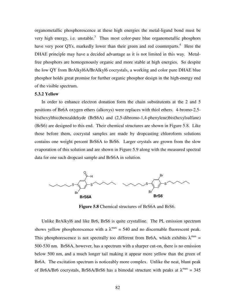
82
organometallic phosphorescence at these high energies the metal-ligand bond must be
very high energy, i.e. unstable.3 Thus most color-pure blue organometallic phosphors
have very poor QYs, markedly lower than their green and red counterparts.4 Here the
DHAE principle may have a decided advantage as it is not limited in this way. Metal-
free phosphors are homogenously organic and more stable at high energies. So despite
the low QY from BrAlkyl6A/BrAlkyl6 cocrystals, a working and color pure DHAE blue
phosphor holds great promise for further organic phosphor design in the high-energy end
of the visible spectrum.
5.3.2 Yellow
In order to enhance electron donation form the chain substitutents at the 2 and 5
positions of Br6A oxygen ethers (alkoxys) were replaces with thiol ethers. 4-bromo-2,5-
bis(hexylthio)benzaldehyde (BrS6A) and (2,5-dibromo-1,4-phenylene)bis(hexylsulfane)
(BrS6) are designed to this end. Their chemical structures are shown in Figure 5.8. Like
those before them, cocrystal samples are made by dropcasting chloroform solutions
contains one weight percent BrS6A to BrS6. Larger crystals are grown from the slow
evaporation of this solution and are shown in Figure 5.9 along with the measured spectral
data for one such dropcast sample and BrS6A in solution.
Unlike BrAlkyl6 and like Br6, BrS6 is quite crystalline. The PL emission spectrum
shows yellow phosphorescence with a λmax
= 540 and no discernable fluorescent peak.
This phosphorescence is not spectrally too different from Br6A, which exhibits λmax
=
500-530 nm. BrS6A, however, has a spectrum with a sharper cut-on, there is no emission
below 500 nm, and a much longer tail making it appear more yellow than the green of
Br6A. The excitation spectrum is noticeably more complex. Unlike the neat, blunt peak
of Br6A/Br6 cocrystals, BrS6A/BrS6 has a bimodal structure with peaks at λmax
= 345
S S
Br
O
H
BrS6A
S S
Br
Br
BrS6
Figure 5.8 Chemical structures of BrS6A and BrS6.

83
nm and λmax
= 419 nm. Reasons for this are uncertain, but both excitation peaks fall
within the relatively weak absorption peak of Br6A that spans 320-430 nm with λmax
=
370 nm and is presumably the S0→S2 transition as seen in Br6A. QYs measured for
these dropcasts were in the 30-35% range, reasonably high but worse than Br6A/Br6
cocrystals. Quantum lifetimes measured τ = 5.5 milliseconds.
This study shows us that exchange of oxygen ethers with thiol ethers is both a viable
color tuning strategy as well as one that retains high crystallinity as seen from oxygen
ethers. QYs are measured somewhat lower, though these cocrystals were not given
nearly the attention that the Br6A/Br6 systems were due to both material availability and
time constraints. There may be optimizations for this system yet unknown. Attempts to
cocrystallize BrS6A and Br6 failed to produce phosphorescent crystals leading us to
deduce that cocrystallizing compounds of differing chain substitutents is a failing
approach. The high crystallinity and reasonable QY of BrS6A/BrS6 cocrystals stand as
very promising evidence that this approach to color tuning and, moreover, the DHAE
principle’s promise of countless new phosphor designs are very viable.
5.3.3 Orange
In order to push phosphorescent emission further into the red end of the visible
spectrum a more dramatic chromophore change is required. Short of attempting selenium
300 400 500 600 700
ExcitationEmission
UV-Abs
Inte
nsity (
a.u
., n
orm
.)
Wavelength (nm)
Figure 5.9 Photo, UV-absorption, PL emission, and PL excitation
spectra of BrS6A/BrS6 cocrystals.

84
ethers, which would be very difficult given the current state of selenium chemistry5 and
not likely to shift the emission greatly, if the rather subtle green-to-yellow shift of BrS6A
is any indication, the core aromatic component must be extended. 5-bromo-2,6-
dihexyloxy-1-naphthaldehyde (Np6A) and 1,5-dibromo-2,6-dihexyloxynaphthalene
(Np6) are designed to add greater electron density to the central chromophore. Their
chemical structures are shown in Figure 5.10.
Dropcast samples of Np6A/Np6 produced very weak phosphorescence, but could be
seen to be very weakly orange emitting. Figure 5.11 shows the PL emission spectra from
samples slow-grown from chloroform solutions containing one weight percent Np6A in
Np6. These samples have a critical difference to those measured thus far: the host
material is emissive. Unlike benzene derivatives, Np6 is conjugated and emits
O
O
Br
O H
O
O
Br
Br
Np6A Np6
Figure 5.10 Chemical structures of Np6A and Np6.
Figure 5.11 Photo, PL emission, and PL excitation spectra of crystals slow
grown from 1 wt% solutions of Np6A/Np6.
300 350 400 450 500 550 600 650 700
Emission from 425 nm ExExcitation of 580 nm EmEmission from 325 nm Ex
Inte
nsity (
a.u
.)
Wavelength (nm)
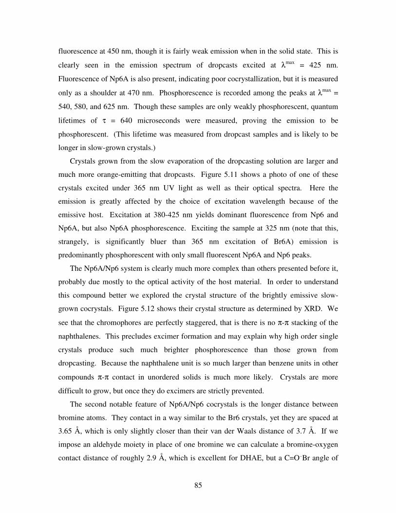
85
fluorescence at 450 nm, though it is fairly weak emission when in the solid state. This is
clearly seen in the emission spectrum of dropcasts excited at λmax
= 425 nm.
Fluorescence of Np6A is also present, indicating poor cocrystallization, but it is measured
only as a shoulder at 470 nm. Phosphorescence is recorded among the peaks at λmax
=
540, 580, and 625 nm. Though these samples are only weakly phosphorescent, quantum
lifetimes of τ = 640 microseconds were measured, proving the emission to be
phosphorescent. (This lifetime was measured from dropcast samples and is likely to be
longer in slow-grown crystals.)
Crystals grown from the slow evaporation of the dropcasting solution are larger and
much more orange-emitting that dropcasts. Figure 5.11 shows a photo of one of these
crystals excited under 365 nm UV light as well as their optical spectra. Here the
emission is greatly affected by the choice of excitation wavelength because of the
emissive host. Excitation at 380-425 nm yields dominant fluorescence from Np6 and
Np6A, but also Np6A phosphorescence. Exciting the sample at 325 nm (note that this,
strangely, is significantly bluer than 365 nm excitation of Br6A) emission is
predominantly phosphorescent with only small fluorescent Np6A and Np6 peaks.
The Np6A/Np6 system is clearly much more complex than others presented before it,
probably due mostly to the optical activity of the host material. In order to understand
this compound better we explored the crystal structure of the brightly emissive slow-
grown cocrystals. Figure 5.12 shows their crystal structure as determined by XRD. We
see that the chromophores are perfectly staggered, that is there is no π-π stacking of the
naphthalenes. This precludes excimer formation and may explain why high order single
crystals produce such much brighter phosphorescence than those grown from
dropcasting. Because the naphthalene unit is so much larger than benzene units in other
compounds π-π contact in unordered solids is much more likely. Crystals are more
difficult to grow, but once they do excimers are strictly prevented.
The second notable feature of Np6A/Np6 cocrystals is the longer distance between
bromine atoms. They contact in a way similar to the Br6 crystals, yet they are spaced at
3.65 Å, which is only slightly closer than their van der Waals distance of 3.7 Å. If we
impose an aldehyde moiety in place of one bromine we can calculate a bromine-oxygen
contact distance of roughly 2.9 Å, which is excellent for DHAE, but a C=O..Br angle of

86
147o, which is very steep for a halogen bond. This may also contribute to the low
brightness measured from these crystals. QYs measured below one percent even for the
brightest crystals.
NpA6/Np6 crystals are complicated, but for the purposes of color tuning they
demonstrate success in dramatic red shifts. Orange phosphorescence that is only visible
in the crystalline state and markedly brighter in high quality crystals, both characteristics
that we have seen from DHAE phosphors prior, is observed. Though there is much
analysis yet to be done on these cocrystals and they are not yet optimized, they lend
promise to the design of both redder, and therefore lower energy, chromophores as well
as the use of compounds more complex than substituted benzaldehydes.
5.3.4 Red
Trying next to achieve the last visible color, red, the effects of naphthalene and thiol
ethers were combined to design 5-bromo-2,6-dihexylthio-1-napthaldehyde (NpS6A) and
3.65 Å
Figure 5.12 Crystal structure of Np6.

87
1,5-dibromo-2,6-dihexylthionaphthalene (NpS6) whose structures are shown in Figure
5.13. The design targeted achieving the same subtle red shift that BrS6A has relative to
Br6A from NpS6A relative to Np6A, turning its orange emission into red. Despite a long
and difficult synthesis, this was not successful.
Cocrystals grown from slow evaporation of a chloroform solution containing one
weight percent NpS6A in NpS6 were completely non-emissive at room temperatures.
XRD reveals the potential reason why. Figure 5.14 shows the crystal structure of
NpS6A/NpS6 cocrystals. There is no halogen-halogen interaction at all.
The bromine atoms are spaced far apart at 4.5 Å, which means that the aldehydes are
also too distant from bromine atoms to exhibit any halogen bonding nor external heavy
atom effect. This demonstrates the greatest challenge to DHAE design; crystal structures
are unpredictable. In this case it appears that halogen bonding between the sulfur atoms
and bromines may be dominating the crystal matrix though this is apparently not the case
in BrS6A/BrS cocrystals.
S
S
Br
O H
S
S
Br
Br
NpS6A NpS6
Figure 5.13 Structures of NpS6A and NpS6.
Figure 5.14 Crystal structure of NpS6.
4.5 Å

88
5.4 Experimental
5.4.1 General Methods
All chemicals used were purchased from Sigma Aldrich and used without further
purification. Deuterated solvents for NMR were purchased from Cambridge Isotope
Laboratories. Proton NMR was conducted on a Varian Inova 500 using CDCl3 solvent
with chemical shifts identified relative to 0.05 v/v% tetramethylsilane standard (0.00
ppm). Anhydrous tetrahydrofuran was generated by refluxing over sodium metal and
benzophenone collected only from deep purple solution.
UV Absorption measurements were collected using a Varian Cary 50 Bio
spectrometer with a solution samples held in a quartz cuvette. PL emission, excitation,
and quantum yield data were collected using a Photon Technologies International (PTI)
Quantamaster system equipped with an integrating sphere. Quantum lifetime data was
collected using a PTI LaserStrobe. Quantum lifetime calculations were carried out on the
FeliX32 software partnered with the PTI equipment. XRD was conducted using a Bruker
SMART APEX CCD-based X-ray diffractometer as described below. Optical
micrographs were collected using an Olympus BX51 optical microscope equipped with a
Mercury lamp UV light source and Olympus DP71 color digital camera.
5.4.2 Synthesis and Characterization
Synthesis of 2-chloro-1,4-dihexyloxybenzne. 2-chlorohydroquinone (1 equiv.) and 1-
bromo-n-hexane (2.5 equiv.) is loaded into a two-neck round bottomed glass flask and
dissolved into dimethylformamide (ca. 1 ml solvent / g chlorohydroquinone). Potassium
carbonate (3 equiv.) is added and the flask is sealed under nitrogen, stirred, and heated to
75oC for 24 hours. The reaction is then cooled, filtered, and rotovaped at high
Scheme 5.1 Synthesis route to Cl6A and Cl6. (i) 2.5 equiv. BrAlkyl6H13, 3 equiv.
K2CO3, DMF, 70-90oC, 24-48h. (ii) 1. 1 equiv. nBuLi, THF, -78
oC, 1h, 2. 4 equiv.
DMF. 23oC, 3h.
HO OH
Cl
C6H13O OC6H13
Cl
(ii)C6H13O OC6H13
CHO
Cl
35% Cl6A, 59%
(i)
C6H13O OC6H13
Cl
II2
H2SO4, ∆,
24h
74%
HO OH
Cl
Cl
C6H13O OC6H13
Cl
Cl
Cl6, 72%
(i)

89
temperature to remove all solvents. This reaction is referred to as Williamson Ether
Synthesis and is referenced in subsequent uses here. The product is purified by column
chromatography with hexanes. A colorless oil was collected at a yield of 35%. 1H NMR
(500 MHz, CDCl3): δ 6.95 (m 1H), 6.87 (m 1H), 6.74 (m 1H), 3.96 (m 2H), 3.90 (m 2H),
1.85-1.73 (m 4H), 1.47 (m 4H), 1.37 (m 8H), 0.93 (m 6H).
Synthesis of 4-chloro-2,5-dihexyloxy-1-iodobenzne. 2-chloro-1,4-dihexyloxybenzne (1
equiv.) is loaded into a two-neck round bottomed glass flask along with iodine (4 equiv.)
and H2SO4 (1 ml / g reagent). The reaction is sealed under argon and refluxed for 24
hours. The reaction is poured into ice water. Solids are collected and recrystallized from
methanol. White crystals are collected at a yield of 74%. 1H NMR (300 MHz, CDCl3): δ
7.33 (s 1H), 6.85 (s 1H), 3.95 (m 4H), 1.82 (m 4H), 1.52 (m 4H), 1.37 (m 8H), 0.93 (m
6H).
Synthesis of 2-choro-1,4-dihexyloxybenzaldehyde (Cl6A). 1,3-dichloro-2,5-
dihexyloxybenzene (Cl6, 1 equiv.) is loaded into a two-neck round bottomed glass flask
and vacuum purged with argon three times. Anhydrous tetrahydrofuran is added by
syringe (ca. 25 ml solvent / g reagent) and the vessel is placed into a bath of dry ice and
2-propanol (-78oC). n-Butyllithium (1 equiv.) is added dropwise via syringe and the
reaction is stirred at -78oC for 1 hour. Anhydrous DMF (4 equiv.) is then added and the
reaction is allowed to warm to 23oC over three hours. The reaction is quenched carefully
with water and extracted with diethylether. The organic layer is collected and dried over
MgSO4 before being filtered and rotovaped to remove solvents. This reaction is
referenced in subsequent uses here are Lithiation. Purification is done by column
chromatography with ethylacetate:hexane (1:30) eluent followed by successive
recrystallizations from methanol and acetonitrile at 23oC. White crystals were collected
at a yield of 59%. 1H NMR (400 MHz, d6-DMSO): δ 10.29 (s 1H), 7.40 (s 1H), 7.29 (s
1H), 4.10 (t 2H), 4.03 (t 2h), 1.72 (m 4H), 1.43 (m 4H), 1.30 (m 8H), 0.89 (m 6H).
Synthesis of 1,4-dichrolo-2,5-dihexyloxybenzene (Cl6). 2,3-dichlorohydroquinone is
alkylated by Williamson Ether synthesis described above. Products are purified by

90
column chromatography with hexanes. White crystals were collected at a yield of 72%.
1H NMR (400 MHz, CDCl3): δ 6.92 (s 2H), 3.91 (t 4H), 1.76 (m 4H), 1.42 (m 4H), 1.30
(m 8H), 0.87 (m 6H).
Synthesis of 1,4-diiodo-2,5-dihexyloxybenzene (I6). 2,5-diiodohydroquinone is reacted
with 1-bromohexane via Williamson ether synthesis as described above. Products are
purified by column chromatography with hexanes. Large colorless crystals were
collected at a yield of 54%. 1H NMR (400 MHz, CDCl3): δ 7.17 (s 2H), 3.92 (t 4H), 1.80
(m 4H), 1.50 (m 4H), 1.34 (m 8H), 0.91 (m 6H).
Synthesis of 2,5-dihexyloxy-4-iodobenzaldehyde (I6A). I6 is reacted to make I6A via
Lithiation as described above. Products were purified by column chromatography with
ethylacetate:hexane (1:30) eluent followed by successive recrystallizations from
methanol at 23oC. White crystals were collected at a yield of 31%.
1H NMR (400 MHz,
d6-DMSO): δ 10.30 (s 1H), 7.68 (s 1H), 7.10 (s 1H), 4.08 (t 2H), 4.00 (t 2h), 1.71 (m
4H), 1.45 (m 4H), 1.32 (m 8H), 0.88 (m 6H).
Sythesis of 2-bromo-1,4-dihexyloxybenzene. 2-bromohydroquinone is converted via
William Ether Synthesis as described above. Products are purified by column
chromatography with hexanes. A colorless oil is collected at a yield of 42%. 1H NMR
Scheme 5.2 Synthesis route to I6A and I6. (i) 2.5 equiv. BrAlkyl6H13, 3 equiv.
K2CO3, DMF, 70-90oC, 24-48h. (ii) 1. 1 equiv. nBuLi, THF, -78
oC, 1h, 2. 4
equiv. DMF. 23oC, 3h.
HO OH
I
I
C6H13O OC6H13
I
I
(ii)C6H13O OC6H13
CHO
I
I6, 54% I6A, 31%
(i)
Scheme 5.3 Synthesis route to H6A. (i) 2.5 equiv. BrAlkyl6H13, 3 equiv. K2CO3,
DMF, 70-90oC, 24-48h. (ii) 1. 1 equiv. nBuLi, THF, -78
oC, 1h, 2. 4 equiv. DMF.
HO OH C6H13O OC6H13
Br
(ii)C6H13O OC6H13
CHO
42% H6A, 79%
(i)
Br

91
(400 MHz, CDCl3): δ 7.08 (s, 1H), 6.79-6.72 (m 2H), 3.91 (t 2H), 3.84 (t 2H), 1.80-1.67
(m 4H), 1.42 (m 4H), 1.30 (m 8H), 0.87 (m 6H).
Synthesis of 1,4-dihexyloxybenzaldehyde (H6A). 2-bromo-1,4-dihexyloxybenzene is
reacted to make H6A by Lithiation as described above. Products were purified by
column chromatography with ethylacetate:hexane (1:30) eluent followed by successive
recrystallizations from methanol at 23oC. White solids were collected at a yield of 79%.
1H NMR (500 MHz, d6-DMSO): δ 10.51 (s 1H), 7.40 (s 1H), 7.32 (m 2H), 4.22 (t 2H),
4.10 (t 2h), 1.91 (m 2H), 1.85 (m 2H), 1.56 (m 4H), 1.45 (m 8H), 1.05 (m 6H).
Synthesis of 1,4-diheptyl-2,5-dibromobenzene (BrAlkyl6). BrAlkyl6 is synthesized
from p-dichlorobenzene following the route reported by Rehahn and coworkers.6 White
crystals are collected at a yield of 53%. 1H NMR (500 MHz, CDCl3): δ 7.71 (s 2H), 2.65
(t 4H), 1.57 (m 4H), 1.37-1.31 (m 16H), 1.08 (m 6H).
Synthesis of 4-bromo-2,5-diheptylbenzaldehyde (BrAlkyl6A). BrAlkyl6 is reacted to
make BrAlkyl6A by Lithiation as described above. Products were purified by column
chromatography with ethylacetate:hexane (1:30). A colorless oil was collected at a yield
of 93%. 1H NMR (500 MHz, CDCl3): δ 10.23 (s 1H), 7.66 (s 1H), 7.47 (s 1H), 2.95 (t
2H), 2.76 (t 2h), 1.61 (m 4H), 1.41-1.28 (m 16H), 0.91 (m 6H).
Synthesis of 1,4-dihexylthiobenzene. 1,4-dibromobenzene is reacted to make 1,4-
dihexylthiobenzene by Lithiation as described above with 1,2-dihexyldisulfane added in
Scheme 5.4. Synthetic route to BrAlkyl6A, BrAlkyl6, BrS6A, and BrS6. (ii) 1. 1
equiv. nBuLi, THF, -78oC, 1h, 2. 4 equiv. DMF, 23
oC, 3h. (iii) 2.05 equiv. Br2,
cat. I2, CH2Cl2, 24h.
Cl Cl
BrMgC7H15(dppp)NiCl2
Et2O, r.t., 24hC7H15 C7H15
C7H15 C7H15
Br
Br
BrC6, 53%
C7H15 C7H15
Br
CHO
BrC6A, 93%
Br Br C6H13S SC6H13 C6H13S SC6H13
Br
Br
BrS6, 46%
C6H13S SC6H13
Br
CHO
BrS6A, 50%
2. S2(C6H13)2,
r.t., 3h
1. nBuLi, THF,
-78oC, 1h (iii)
(iii) (ii)
(ii)

92
place of DMF in step 2. A pungent yellow oil is collected at yields of 20-30%. 1H NMR
(400 MHz, CDCl3): δ 7.23 (s 2H), 2.88 (t 4H), 1.61 (m 4H), 1.44 (m 4H), 1.28 (m 8H),
0.86 (m 6H).
Synthesis of 1,4-dihexylthio-2,5-dibromobenzene (BrS6). 1,4-dihexylthiobenzene (1
equiv.) is loaded into a two-neck round bottomed flask along with catalytic iodine (0.05
equiv.) and CCl2H2 (10 ml / g reagent.) The vessel is sealed and cooled to 0oC buy an ice
bath. Bromine (2.05 equiv.) is added dropwise by syringe and the reaction is stirred at
room temperature for 24 hours. The reaction is quenched with 20% potassium hydroxide
solution and extracted with CCl2H2. Solvents are removed by rotavap and the product is
purified by recrystallization from methanol. White crystals are collected at a yield of
46%. 1H NMR (400 MHz, CDCl3): δ 7.36 (s 2H), 2.91 (m 4H), 1.71 (m 4H), 1.46 (m
4H), 1.31 (m 8H), 0.91 (m 6H).
Synthesis of 4-bromo-2,5-dihexylthiobenzaldehyde (BrS6A). BrS6 is reacted to make
BrS6A by Lithiation as described above. Products were purified by column
chromatography with ethylacetate:hexane (1:30) eluent followed by successive
recrystallizations from methanol at 23oC White crystals were collected at a yield of 50%.
1H NMR (500 MHz, CDCl3): δ 10.39 (s 1H), 7.64 (s 1H), 7.61 (s 1H), 2.97 (t 2H), 2.92 (t
2h), 1.71 (m 4H), 1.47 (m 4H), 1.32 (m 8H), 0.89 (m 6H).
Synthesis of 2,6-dihexyloxynaphthalene. 2,6-dihydroxynaphthalene is alkylated by
Williamson Ether Synthesis as described above. Products are purified by column
chromatography with hexanes. Colorless flake crystals were collected at modest yields
HO
OH (i)
C6H13O
OC6H13
2x Br2,
0.4x Fe
CCl4, 0oC,
20 min
C6H13O
OC6H13
Br
Br
Np6, 77%
C6H13O
OC6H13
Br
CHO
(ii)
Np6A, 7%
10-20%
Scheme 5.5 Synthesis route to Np6A and Np6. (i) 2.5 equiv. BrAlkyl6H13, 3 equiv.
K2CO3, DMF, 70-90oC, 24-48h. (ii) 1. 1 equiv. nBuLi, THF, -78
oC, 1h, 2. 4 equiv.
DMF.

93
of 10-20%. 1H NMR (500 MHz, CDCl3): δ 7.54 (d 2H), 7.15 (d 2H), 7.11 (s 2H), 4.06 (t
4H), 1.85 (m 4H), 1.53 (m 4H), 1.39 (m 8H), 0.95 (m 6H).
Synthesis of 1,5-dibromo-2,6-dihexyloxynaphthalene (NpS6). 2,6-
dihexyloxynaphthalene (1 equiv.) is loaded into a two-neck round bottomed glass flask
and is dissolved into carbon tetrachloride (1 ml / g reagent). A solution of powdered iron
(0.4 equiv.) in carbon tetrachloride is added to the center of the stirring reaction mix. The
reaction is cooled to 0oC by an ice bath and sealed before bromine (2 equiv.) is added
dropwise. The reaction is stirred at 0oC for 20-30 minutes then quenched by 10% sodium
hydrogen sulfite / water solution. Once all color is gone, the reaction is extracted with
CCl2H2 and water. This method will be referred to as a Friedel-Crafts reaction in
subsequent steps. Organic solvents are removed by rotavap and resulting solids are
recrystallized from methanol. White needle crystals were collected at a yield of 77%. 1H
NMR (500 MHz, CDCl3): δ 8.21 (d 2H), 7.31 (d 2H), 4.18 (t 4H), 1.88 (m 4H), 1.56 (m
4H), 1.37 (m 8H), 0.93 (m 6H).
Synthesis of 5-bromo-2,6-dihexyloxy-1-naphthaldehyde (Np6A). Np6 is reacted to
make Np6A by Lithiation as described above. Products were very carefully purified by
column chromatography to isolate them from numerous byproducts with
ethylacetate:hexane (1:30) eluent followed by successive recrystallizations from
methanol at 23oC. Yellow solids were collected at a yield of 7%.
1H NMR (500 MHz,
CDCl3): δ 10.89 (s 1H), 9.30 (d 2H), 9.53 (d 2H), 4.23 (t 2H), 4.17 (t 2H), 1.88 (m 4H),
1.54 (m 4H), 1.37 (m 8H), 0.92 (m 6H).
HO
O H
12x H SC6H 13
0 .4x TsOH
Ben zene , ∆, 10h C6H13S
SC 6H 13
70-90%
2x Br2 ,
0 .4 x Fe
CCl4, 0oC,
20 min
C6H13S
SC 6H 13
Br
Br
N pS6,85%
Scheme 5.6 Synthetic route to NpS6 and NpS6A.
C6H13S
SC6H13
Br
Br
7.8 %
C6H13S
SC6H13
Br
CN
2x CuCN
DMF, 80oC,
10 h
Al
H
CH2Cl2, 0oCC6H13S
SC6H13
Br
CHO
NpS6A, 11.5%

94
Synthesis of 2,6-dihexylthionaphthalene. 2,6-dihydroxynaphthalene (1 equiv.) is
loaded into a 2-neck round bottomed glass flask along with hexane-1-thiol (12 equiv.)
and Tosyl acid (0.4 equiv.). The solids are dissolved into benzene (5 ml / g reagent) and
refluxed for 10-24 hours. The reaction is stopped by removing volatile solvents by
rotavap. Products are purified by column chromatography using a diethylether:hexanes
(1:10) eluent. A fluffy white powder is collected at yields of 80-90%. 1H NMR (500
MHz, CDCl3): δ 7.66 (s 2H), 7.62 (d 2H), 7.39 (d 2H), 3.00 (t 4H), 1.68 (m 4H), 1.45 (m
4H), 1.28 (m 8H), 0.88 (m 6H).
Synthesis of 1,5-dibromo-2,6-dihexylthionaphthalene (NpS6). 2,6-
dihexylthionaphthalene is reacted to make NpS6 by Friedel-Crafts reaction described
above. Organic solvents are removed by rotavap and resulting solids are recrystallized
from methanol. White powder is collected at a yield of 85%. 1H NMR (500 MHz,
CDCl3): δ 8.20 (d 2H), 7.43 (d 2H), 3.05 (t 4H), 1.77 (m 4H), 1.52 (m 4H), 1.33 (m 8H),
0.91 (m 6H).
Synthesis of 5-bromo-2,6-dihexylthio-1-naphthonitrile. NpS6 (1 equiv.) is loaded into
a 2-neck round bottom glass flask along with copper cyanide (1 equiv.). The reagents are
dissolved in DMF (10 ml / g reagent) and stirred at 80oC for 24 hours. The reaction is
quenched when solvents are removed by high temperature rotavap. Products are isolated
by careful column chromatography in ethylacetate:hexanes (1:2) eluent. Yellow solids
are collected at a yield of only 7.8%. 1H NMR (500 MHz, CDCl3): δ 8.34 (d 1H), 8.07 (d
1H), 9.53 (d, 2H), 4.23 (t, 2H), 4.17 (t 2H), 1.88 (m 4H), 1.54 (m 4H), 1.37 (m 8H), 0.92
(m 6H).
Synthesis of 5-bromo-2,6-dihexylthio-1-naphthaldehyde (NpS6A). 5-bromo-2,6-
dihexylthio-1-naphthonitrile (1 equiv.) is loaded into a two-neck round bottom glass flask
and dissolved into CCl2H2 (10 ml / g reagent) before being cooled to 0oC by an ice bath.
Diisobutylaluminum hydride (1.1 equiv.) is added and the reaction is stirred for one hour
at 0oC. The reaction is quenched with water, extracted, and dried by rotavap. Products

95
are carefully isolated by column chromatography using a ethylacetate:hexanes (1:10)
eluent. A yellow solid is collected at a yield of 11.5%. 1H NMR (500 MHz, CDCl3): δ
10.96 (s 1H), 8.94 (d 1H), 8.43 (d 1H), 7.66 (d 1H), 7.48 (d 1H), 3.06 (p 2H), 1.73 (m
4H), 1.50 (m 4H), 1.32 (m 8H), 0.92 (m 6H).
Crystal Strcuture of Np6A/Np6 Cocrystals. The following analysis was conducted and
report written by University of Michigan Department of Chemistry staff crystallographer
Dr. Jeff W. Kampf as a paid service. Colorless plates of NpA6 were grown from a
dichloromethane solution at 23 deg. C. A crystal of dimensions 0.28 x 0.24 x 0.04 mm
was mounted on a Bruker SMART APEX CCD-based X-ray diffractometer equipped
with a low temperature device and fine focus Mo-target X-ray tube (λ = 0.71073 A)
operated at 1500 W power (50 kV, 30 mA). The X-ray intensities were measured at
85(1) K; the detector was placed at a distance 5.055 cm from the crystal. A total of 5190
frames were collected with a scan width of 0.5° in ω and 0.45° in phi with an exposure
time of 20 s/frame. The integration of the data yielded a total of 23451 reflections to a
maximum 2θ value of 56.68° of which 2565 were independent and 2417 were greater
than 2σ(I). The final cell constants (Table 5.1) were based on the xyz centroids of 9995
reflections above 10σ(I). Analysis of the data showed negligible decay during data
collection; the data were processed with SADABS and corrected for absorption. The
structure was solved and refined with the Bruker SHELXTL software package, using the
space group P1bar with Z = 1 for the formula C22H30O2Br2•. All non-hydrogen atoms
were refined anisotropically with the hydrogen atoms placed in idealized positions. The
cluster lies on an inversion center of the crystal lattice. Full matrix least-squares
refinement based on F2 converged at R1 = 0.0292 and wR2 = 0.0794 [based on I >
2sigma(I)], R1 = 0.0314 and wR2 = 0.0816 for all data.
• Sheldrick, G.M. SHELXTL, v. 2008/4; Bruker Analytical X-ray, Madison, WI, 2008.
• Sheldrick, G.M. SADABS, v. 2008/1. Program for Empirical Absorption Correction
of Area Detector Data, University of Gottingen: Gottingen, Germany, 2008.
• Saint Plus, v. 7.60A, Bruker Analytical X-ray, Madison, WI, 2009.

96
5.5 Conclusions
Here we have taken the DHAE principle and used it to synthesize organic phosphors
of varying color by controlling the electron density of the chromophore. By altering the
halogen on the aldehyde, fine tuning can be achieved in discrete 5 nm steps. Chlorinated
chromophores emit 5 mn bluer than brominated chromophore and iodinated
chromophores emit 5 nm redder. Brominated chromophores, though, exhibit the best
cocrystallization because they more closely match the volumetric size and shape of their
analogous aldehyde. Thus bromine combinations yield the brightest phosphors. The
aldehyde can be removed altogether to achieve a broad blue shift of nearly 30 nm, but
this comes at the price of inefficient cocrystallization and weakened intrinsic intersystem
crossing of the chromophore. Inclusion of halogen-free aldehydes into heavily
halogenated hosts is inefficient and, without the benefit of the internal heavy atom effect,
fluorescence may dominate singlet decay.
More dramatic changes to the chromophore afford more dramatic changes to the
emission color. Alkyl variants donate less electron density and thus exhibit larger
bandgaps than the green-emitting BrNA/BrN family of phosphors. BrAlkyl6A/BrAlkyl6
Name Np6
Formula C22H30Br2O2
Space Group P-1
Cell Lengths a 7.6936(11) b 8.5442(12) c 9.4750(14)
Cell Angles αααα 108.286(2) ββββ 110.770(2) γγγγ 102.065(2)
Cell Volume 515.721
Z, Z’ Z: 1 Z’: 0
R-Factor (%) 2.92
Name Np6
Formula C22H30Br2S2
Space Group P 21/c
Cell Lengths a 10.8625(6) b 14.0253(8) c 8.0484(4)
Cell Angles α α α α 90 β β β β 110.843(2) γ γ γ γ 90
Cell Volume 1145.93
Table 5.1 Crystallographic Data for Np6.
Table 5.2 Crystallographic Data for NpS6.

97
cocrystals produce very color pure blue phosphorescence, though they exhibit low QYs
due in part to their poor crystallinity and low melting temperature. Thiol ethers used in
replacement of oxygen ethers red-shift the emission of Br6A slightly while maintaining
good cocrystallinity and moderate QYs. BrS6A/BrS6 cocrystals emit yellow
phosphorescence, similar spectrally, but not visibly, to Br6A. Finally, Naphthyl variants
have even more electron density at their core chromophore, which narrows the bandgap
to the point where Np6A/Np6 cocrystals emit visibly orange phosphorescence. Each of
these several examples supports the color tuning approach of altering electron density at
the aromatic ketone chromophore and can be used as a guide to developing future DHAE
phosphors. This work also supports the DHAE design principle’s promise to be useful
for the design of a broad family of metal-free organic phosphor.
This work does, however, highlight some of the challenges to DHAE phosphor
design. First, the blue-emitting BrAlkyl6A/BrAlkyl6 system produces nice color, but
very poor QY because its structure has low crystallinity. As the design trends toward
certain structures these complications may limit the practical usefulness of blue and near-
UV phosphors. Second, cross-mixing of dramatically different chromophores
(BrAlkyl6A / Br6 or BrS6A / Br6) failed to produce efficient emission (or any at all in
the later case), which highlights that the cocrystallization can be quite difficult to achieve
unless the host and aldehyde are ideally sized. Lastly, the weak emission of orange-
emitting Np6A/Np6 and the failed attempt to observe red emission from NpS6A/NpS6
show how difficult it is to predict the crystal structure of a given compound. We can
design chromophores with the intention that they exhibit strong halogen bonding, but we
cannot control this absolutely. Until the efficacy of crystal engineering improves,
researchers may be left to trial-and-error when designing new DHAE phosphors.

98
5.6 References
1 O. Bolton, K. Lee, K.K. Yien, K.Y. Lin, S.M. Wang, M.T. Gray, J.W. Kampf, and J.
Kim manuscript in preparation. 2 O. Bolton, K. Lee, H.-J. Kim, K.Y. Lin, and J. Kim Nature submitted.
3 D. Gebeyehu, K. Walzer, G. He, M. Pfeiffer, K. Leo, J. Brandt, A. Gerhard, P. Stößel,
H. Vestweber, Synth. Met. 2005, 148, 205. 4 Y. Kawamura, S. Yanagida, and S.R. Forrest J. Appl. Phys. 2002, 92, 87.
5 D.M. Freudendahl, S.A. Shahzad, and T. Wirth Eur. J. of Org. Chem. 2009, 11, 1649.
6 M. Rehahn, A.-D. Schlüter, W.J. Feast Synthesis 2009, 5, 386.

99
Chapter 6
Delayed Phosphorescence
With the DHAE principle now clearly defined and its capabilities demonstrated, this
chapter delves into an unexpected discovery from crystals of Br6A, delayed
phosphorescence. Here, the phenomenon of delayed emission is described by first
explaining the well-established concept of delayed fluorescence. Excimers are then
explained in greater detail as they are a critical part of this chapter’s finding. Delayed
phosphorescence, analogous to delayed fluorescence, is observed and reported here for
the first time. As evidenced here, this emission pathway accounts for the phosphorescent
emission observed from pure Br6A crystals. The excited state travels through an excimer
state before emitting as pure triplets. This holds promise for optical device applications
where excimers are generally considered a quenching mechanism. The possibility of
delayed phosphorescence demonstrates that emission can be reclaimed from these
otherwise detrimental states.

100
6.1 Introduction
The findings described in this chapter are ancillary to the DHAE design principle,
though understanding them draws heavily from the same set of excited state analyses.
First we describe two concepts that have not been explained in great detail thus far,
delayed fluorescence and excimers. The combination of these two effects, in the
discovery described here, yields a pathway to enhance phosphorescent QY for certain
systems and optical devices. We present thermally activated delayed phosphorescence.
(Literature has used the term “delayed phosphorescence” to describe a variety of
time-dependent phosphorescent observations. The finding reported here is not to be
confused with “microwave-induced delayed phosphorescence”1 or “heat pulse-induced
delayed phosphorescence,”2 which refer to extremely low temperature systems where the
three different triplet states Tx, Ty, and Tz can be distinguished dynamically. A report by
Lamola comes closest to that reported here, but refers to an inter-species triplet-triplet
crossing.3)
6.1.1 Delayed Fluorescence
When a singlet flips by intersystem crossing into a triplet state there will occasionally
occur a process by which the triplet then flips back into the singlet. Triplets, of course,
are always of lower energy than their corresponding singlets. With one famous
exception,4 Tn < Sn. Thus for a T1 triplet to convert back to an S1 singlet, there must be
some outside energy assisting the transition. If that singlet then emits the result is
emission that is spectrally fluorescent but with the long lifetime of a triplet state. This is
the phenomenon of delayed fluorescence.5,6
There are two main energetic sources that facilitate this up-conversion. One
possibility is the interaction of two excited states combining to raise one while relaxing
the other. The states are often triplets because they live long enough for this slow
intermolecular reaction to occur. In a formula notation: T1 + T’1 → S1 + S’0. This is
triplet-triplet annihilation. This method is intermolecular and is therefore correlated to
the square of the chromophore concentration and the square of the exciting emission
intensity.7 Another method of T1 → S1 can occur if the vibrational modes of T1 overlap
with those of S1. This transition can be facilitated by heat energy. In formula: T1 + heat

101
→ S1. This method is, of course, highly dependent on temperature and can be greatly
reduced at lower temperatures.
The three critical identifying aspects of delayed fluorescence are 1. emission that is
spectrally identical to regular, “prompt” fluorescence, 2. lifetimes that are in the triplet
regime, microseconds or longer, and 3. emission intensity that is inversely proportional to
temperature. The method of internal up-conversion can be probed by temperature and
sample concentration.
6.1.2 Excimers
The concept of delayed fluorescence is sometimes referred to more generally as
delayed emission, implying that it is theoretically possible that it may occur for
phosphorescence as well. This could be the possibility of a triplet up-converting to a
singlet before intersystem crossing back to a triplet before emitting, but reports of such an
observation are absent. The other possibility would be triplets being up-converted from a
lower energy state. Almost by definition, T1 is the lowest excited state of any molecule
so a lower energy state could only be an intermolecular state, such as a triplet excimer or
exciplex.
Excimers are a concept that has been described only in brief terms here thus far.
They, simply, are a combination of an excited state molecule interacting with a ground
state molecule to stabilize the overall system. If these molecules are the same species
their grouping forms an excimer, otherwise, if they are two different species, they are
referred to as an exciplex. These typically lead to non-emissive internal conversion
through vibrational dissipation. Excimers can occur from either singlet8,9,10,11
or triplet
excited states.12
Excimers form because both molecules (excited and ground state) are usually very
easily polarized. Once one is exited it becomes highly polarized and imparts opposite
polarity in the potential excimer partner nearby. The two align with head-to-toe poles to
stabilize the overall energy. Because of this stabilization, excimers typically have longer
lifetimes than the monomer excited state, but their lowered energy and the additional
vibrational modes associated with two species often lead to non-emissive relaxation.13,14
Because of this interaction necessary in this relationship, excimer formation requires that

102
the molecules be aligned ideally for this head-to-toe interaction, or have the freedom to
become so. Studies with aromatic systems have demonstrated that the distance between
aromatic species necessary for excimer formation is 3-4 Å.15
As stated, excimers typically contain very competitive internal conversion
mechanisms and, with unusual exception, are non-emissive.16,17
As such they are seen as
a detrimental phenomenon in optical materials for devices, often referred to along with
other emission-restricting phenomena as “self-quenching”. Because of this they are
avoided in material and device design. To this end, chromophores are strictly diluted to
prevent any intermolecular interaction of this nature. The prevention of excimers is
universally accepted as the proper approach in emissive applications. Our results show
the first report of delayed phosphoresce from triplet states repopulated from triplet
excimers.18
This demonstrates the possibility to reclaim emission from these complexes
heretofore believed to be unavoidably quenching.
6.2 Results and Discussion
From chapter 3 we see that crystals of pure Br6A emit green phosphorescence at λmax
= 500-530 nm. Upon further investigation we can conclude that this emission is actually
delayed phosphoresce. Dynamic measurements as well as spectral observations at high
and low temperatures support the hypothesis that this emission comes from T1 states in
Br6A that have been thermally repopulated from a lower energy triplet excimer.
Phosphorescent emission from Br6A crystals is spectrally identical to emission seen
from the Br6A/Br6 cocrystals from Chapter 4. Figure 6.1 shows the PL emission and
excitation spectra of each of these samples. The emissions agree very well (with the
exception of the fluorescent emission from the unordered portion of Br6A, which is
discussed in Chapter 3). The excitation spectra, on the other hand, are suspiciously
divergent. Cocrystals exhibit a very narrow excitation window centered at λmax
= 365 nm
while pure Br6A crystals exhibit a much broader excitation with two peaks, one at λmax
=
320 nm and another with twice the intensity at 390 nm. Taken alone this indicates only
that the excitation pathways are not the same in both materials, though the emission from
each comes from the same state, T1 of Br6A. The dramatic differences in the shape of
the excitation spectra indicate that the excited state pathways to emission are likely very

103
different. For example, exposure of the cocrystals to 325 nm light produces no emission,
yet pure Br6A crystals exposed to the same light produce significant phosphorescence.
Paired with the following evidence, this clearly indicates that the excited states in Br6A
crystals travel through an excimer state before finally emitting as triplets.
Another very telling finding comes from the phosphorescent lifetimes of these two
samples. Figure 6.2 shows the phosphorescent decay curves of both pure Br6A and 0.01
weight fraction (as Br6A) Br6A/Br6 cocrystals. Both are very similar, 5.4 ms and 8.3 ms
0 5 10 15 20 25 30
Br6ACalculatedBr6A/Br6Calculated
Inte
nsity (
a.u
.)
Time (ms)
ττττ = 8.3 ms
ττττ = 5.4 ms
Figure 6.2 Phosphorescent decay curves of Br6A and Br6A/Br6 crystals.
Figre 6.1 PL emission and excitation spectra of Br6A and Br6A/Br6
crystals. Br6A excitation (dotted), Br6A emission (small dash),
Br6A/Br6 excitation (long dash), Br6A/Br6 emission (solid).
250 300 350 400 450 500 550 600 650
Inte
nsity (
a.u
., n
orm
.)
Wavelength (nm)

104
respectively, which makes sense until we consider their enormous difference in QY.
Equation 1.3 relates the rate of any excited state transition to its QY and lifetime, here kPh
= ΦPh/τPh. Br6A, in best case, exhibits QY of only ΦPh = 2.9% (0.029) while the
cocrystals yield, in general, ΦPh = 55% (0.55). From this we see that the phosphorescent
rates do not agree: kPh(Br6A) = 5 s-1
, kPh(Br6A/Br6) = 66 s-1
. Emission from pure Br6A
is over twelve times slower than from cocrystals though their emission is both from T1 of
Br6A. This is very clear evidence of delayed phosphoresce: phosphorescence from Br6A
crystals is much slower than that from cocrystals. One may point to the possibility that
the presence of Br6 affects kPh in cocrystals but, as chapter 4 addresses thoroughly, Br6 is
optically non-interacting with Br6A because of its higher energy excited states.
Furthermore, Br6 is highly non-polar and non-polarizable precluding the possibility of
exiplex formation.
For further evidence low temperature analysis in employed. In delayed
phosphorescence (unlike delayed fluorescence) it is likely that the triplet state is
repopulated from heat and not triplet-triplet annihilation as final emission comes from a
triplet state. Figure 6.3 shows photos of Br6A crystals under 365 nm UV light at 298 K
and 77K as well as the PL emission and excitation spectra of these samples. The photo
shows an obvious change; at 77 K Br6A crystals emit yellow rather than the green that
300 350 400 450 500 550 600 650
Inte
nsity (
a.u
., n
orm
.)
Wavelength (nm)Figure 6.3 Photo and PL emission and excitation spectra of Br6A crystals at 298 K
and 77 K. Photos: 298 K (left), 77 K (right). Spectra: 298 K excitation (dotted),
298 K emission (short dash), 77 K excitation (long dash), and 77K emission (solid).

105
they emit at room temperature. The spectral data supports this. Here the data is
normalized to the fluorescent emission at 420 nm. This is done because the fluorescent
transition S1→S0 + hν is unaffected by temperature and thus provides a constant between
the two samples for comparison.19
The excitation spectra are not dramatically different,
and we can see in emission that a wider portion of the S1 vibrational modes are now
emissive by the broader peak at 420 nm, but the striking change is in the phosphorescent
emission. The λmax
= 500 nm “green” peak seen at 298 K is entirely gone at 77 K and in
its place is a much stronger peak appears at λmax
= 530 nm. Though both the green and
yellow peaks are close in position, we can be sure that the λmax
= 500 nm is gone because
it is absent in the normalized spectra. For direct phosphorescence this is counterintuitive.
Normally phosphorescence emission is enhanced by low temperatures as vibrational
freedoms are restricted to reduce non-emissive relaxation. Here low temperatures
extinguish the phosphorescence indicating that it is thermally populated, delayed,
phosphorescence. The yellow emission seen only at 77 K is from triplet excimers that are
relaxed vibrationally (or converted to T1) at room temperature and made emissive only
when frozen at low temperature. This is represented schematically in Figure 6.4.
The presence of excimers can be speculated by the Br6A crystal structure and proven
by controlling intermolecular contact in low temperature samples. Recall from Chapter 4
that crystals of pure Br6A exhibit strong head-to-tow overlap between the benzaldehyde
Figure 6.4 Excited state diagrams of Br6A crystals at 298 K and 77 K. 298 K (left) and
77 K (right). T1+S0 represents the triplet excimer state. Absorption (S2→S1) is omitted
for simplicity.
T1+S0 heat
S0
T2 S1
T1
Delayed
Phos.
Vibrational
Dissipation
T1+S0
S0
T2 S1
T1
Excimer
Emission

106
moieties with inter-aromatic distance of 3.5-3.7 Å, which are sufficiently close for
excimer formation. Also note that the head-to-toe arrangement is ideal for excimer
polarization stabilization. Empirical evidence comes from comparing Br6A crystals at 77
K to glassy solutions of Br6A also at 77 K as shown in Figure 6.5. In the glassy solution
(concentration 0.5 µM) molecules of Br6A are isolated from one another and we see pure
green emission at λmax
= 500 nm as well as a single thin excitation peak at 360 nm, both
in perfect agreement with Br6A/Br6 cocrystals. Clearly the yellow emission comes from
an intermolecular excited state species of Br6A as it is absent in solution. Being that this
state is lower in energy than T1 (its emission is redder) we must assume that it is a triplet
excimer though the exact pathway from S1 to T1-S0 (excimer) can only be speculated
from the data.
6.3 Experimental
6.3.1 General Methods
All chemicals used were purchased from Sigma Aldrich and used without further
purification. Deuterated solvents for NMR were purchased from Cambridge Isotope
Laboratories. Proton NMR was conducted on a Varian Inova 500 using CDCl3 solvent
with chemical shifts identified relative to 0.05 v/v% tetramethylsilane standard (0.00
Figure 6.5 PL emission and excitation of Br6A crystals and Br6A in glassy
toluene solution each at 77 K. Crystal excitation (dotted), crystal emission
(long dash), solution excitation (short dash), and solution emission (solid).
300 350 400 450 500 550 600 650
Inte
nsity (
a.u
., n
orm
.)
Wavelength (nm)

107
ppm). Anhydrous tetrahydrofuran was generated by refluxing over sodium metal and
benzophenone collected only from deep purple solution.
PL emission, excitation, and quantum yield data were collected using a Photon
Technologies International (PTI) Quantamaster system equipped with an integrating
sphere. For low temperature PL measurements a custom made liquid nitrogen dewar
specifically designed for the PTI Quantamaster was used. Quantum lifetime data was
collected using a PTI LaserStrobe. Quantum lifetime calculations were carried out on the
FeliX32 software partnered with the PTI equipment.
6.3.2 Synthesis and Characterization
Br6A and Br6 were both synthesized by the methods reported in Chapters 3 and 4. No
new materials were synthesized for this study. Also, referenced crystal structures were
collected by the analysis methods reported in Chapters 3 and 4 also.
6.4 Conclusions
Pure crystals of Br6A exhibit delayed phosphorescence. Their phosphorescent
emission is much slower than that of Br6A/Br6 cocrystals and they exhibit none of the
green, room temperature phosphorescent emission at low temperature. Br6A molecules
align in crystals in ideal intermolecular orientations for strong head-to-toe polar
interactions such as those seen from excimers. This along with evidence of a low energy
excited state seen only from intermolecular species strongly suggests that triplet excimers
are formed in Br6A crystals. At room temperature a portion of these triplet excimers
transition thermally to pure triplets of Br6A, which then emit this delayed
phosphorescence. Delayed phosphorescence from pure Br6A crystals is over twelve
times slower than from Br6A/Br6 cocrystals.
Excimers are considered to be detrimental species whose existence only reduces
device efficiency. Here, by demonstrating the first report of delayed phosphorescence,
we prove the possibility that emission can be reclaimed from these otherwise highly
quenching excimer states. This provides the potential that phosphors can be designed to
experience less detriment from excimer formation and may also present possibilities for
dynamic detection methods.

108
6.5 References
1 J. Schmidt, W.S. Veeman, and J.H. van der Waals Chem. Phys. Lett.1969, 4, 341.
2 A.I. Attia, B.H. Loo, and A.H. Francis J. Chem. Phys. 1974, 61, 4527.
3 A.A. Lamola J. Am. Chem. Soc. 1970, 92, 5045.
4 M. Beer and H.C. Longuet-Higgins J. Chem. Phys. 1955, 23, 1390.
5 B. Stevensm E. Hutton, and G. Porter Nature, 1960, 185, 917.
6 B. Hu, L.A. Yan, and M. Shao Adv. Mater. 2009, 21, 1500.
7 A, Yekta and N.J. Turro Chem. Phys. Lett 1972, 17, 32.
8 P.P. Wells and H. Morrison J. Am. Chem. Soc. 1975, 97, 154.
9 M. Yanagidate, K. Takayama, M. Takeuchi, J. Nishimura, and H. Shizuka J. Phys.
Chem. 1993, 97, 8881. 10
R.G. Sadygov and E.C. Lim Chem. Phys. Lett. 1994, 225, 441. 11
G. Olaso-Gonzalez, D. Roca-Sanjuan, L. Serrano-Andres, M. Merchan J. Chem. Phys.
2006, 125, 231102. 12
triplet excimer examples 13
T. Forster Angew. Chem.-Intl. Ed. 1969, 8, 333. 14
H. Beens and A. Weller Organic Molecular Photophysics, ed. J.B. Birks, Vol. 2 (Wiley
New York, NY 1975). 15
S. A. Jenekhe & J. A. Osaheni Science 265, 765, (1994). 16
J. Langelaar, R.P.H. Rettschnick, A.M.F. Lamrooy, and G.J. Hoytink Chem. Phys. Lett.
1968, 1, 609. 17
C. Rothe, S. Hintschich, A.P. Monkman, N. Svensson, and M.R. Anderson J. Chem.
Phys.2002, 116, 10503. 18
O. Bolton and J. Kim manuscript in preparation. 19
Turro, N.J. Modern Molecular Photochemistry (University Science Books, Sausalito
CA, 1991).

109
Chapter 7
Dimethoxybromobenzaldehyde
This chapter deals specifically with a unique member of the Brn family, 2,6-
dimethoxy-4-bromobenzaldehyde (Br1A). This versatile compound was discovered to be
not only equally bright to the best combinations of larger Brn phosphors but also much
simpler to synthesize and purify, highly polymorphic, and readily subliming to create
bright and unique microstructures. These benefits make Br1A/Br1 cocrystals uniquely
suited to further research in metal-free organic phosphor applications.

110
7.1 Introduction
Of all of the DHAE phosphors demonstrated so far in this work, it is the BrnA/Brn
family that exhibits the highest quantum yields. The yellow emitting BrS6A/BrS6
phosphor is comparable, but all others fail in initial research to improve upon the 50-60%
QY seen from Br6A/Br6. Excellent though these phosphors are, they still exhibit a
number of undesirable traits. They are highly electrically insulating due their long alkoxy
chain substitutents.1,2
They can be difficult to purify because of the structurally similar
impurities readily generated during the asymmetric lithiation step in their synthesis.3,4
Finally, their relatively low melting temperatures (55-65oC) lead to problems of
practicality in device use and may inhibit efficient cocrystallization during crystal
formation.5,6
An alternative exists in the smallest members of the BrnA/Brn family, 2,6-
dimethoxy-4-bromobenzaldehyde (Br1A) and 1,4-dibromo-2,6-dimethoxybenzene (Br1),
whose chemical structures are shown in Figure 7.1.7 These compounds exhibit high QYs,
have greatly reduced alkyl character, are easier to synthesize/purify, and they do not melt
below 100oC. In fact, they do not melt at all but sublime at temperatures of 110
oC (for
Br1A) and 140oC (for Br1) in atmospheric pressure. From sublimation, monodisperse
rod-shaped crystals can be grown with controllable size, which is useful as control of
micro and nano-scale fabrication is critical in materials science.8,9,10
These collected
characteristics make Br1A/Br1 an attractive alternative to larger BrnA/Brn phosphors,
but the last gives it unique properties promising for future application development.
7.2 Results and Discussion
The synthetic route to Br1A is much simpler than that of BrnA (where n > 1) given
the current state of commercial precursor availability. Rather than using an asymmetric
O O
O
H
Br
Br1A
O O
Br
Br
Br1
Figure 7.1 Structures of Br1A and Br1.

111
lithiation step to convert Br1 into Br1A, 2,5-dimethoxybenzaldehyde can be brominated
directly to Br1A in a reaction that is non-asymmetric and very clean. Purification can be
achieved either by simple recrystallization or sublimation, for stricter purity
requirements. Br1 is also synthesized by direct bromination of 1,4-dimethoxybenzene
and purified into very large colorless crystals by solvent recrystallization. Both
compounds are prepared by bromination without need of additional reagents or catalysts,
metallic or otherwise. The fundamental reason that these compounds are so much easier
to synthesize is because of their extremely short alkoxy substitutents. Though they are
technically alkoxy, methoxy groups are so short they behave as pseudo-functional groups
and can be grafted directly to the benzaldehyde in commercial processes. See section
7.3.2 for full synthetic details.
Br1A and Br1 are readily soluble in a wide variety of organic solvents. Unlike
longer-chain Brn compounds they are poorly soluble in low polarity solvents such as
hexanes and diethylether but are, in exchange, more soluble in alcohols. These
compounds are also noticeably more crystalline that longer-chain Brn compounds,
particularly Br1, which forms large millimeter-to-centimeter dimension crystals readily
from solvent evaporation.
0
0.1
0.2
0.3
0.4
0.5
0.6
0.7
0.001 0.01 0.1
Br1A/Br1Br6A/Br6
QY
(Φ
)
Weight Fraction BrNA
Figure 7.2 Quantum yields of dropcast Br1A/Br1 cocrystals at pertinent
weight fractions of Br1A as compared to Br6A/Br6 dropcast cocrystals.

112
Dropcast samples from chloroform solutions of one weight percent Br1A to Br1
exhibit emission that is spectrally identical to longer-chain Brn phosphors and QYs
measured as high as 62% as shown in Figure 7.2. This brightness is very competitive
with Br6A/Br6 cocrystals, which have exhibited QYs with averages in the 50-55% range.
Cocrystals of Br1A/Br1 also appear noticeably brighter than others because of their high
chromophore density. Br1A is 36% lighter than Br6A and roughly 66% shorter, meaning
that the cocrystal is much denser.
Because the alkoxy substitutents are so short on Br1A and Br1 they no longer play
such a large part in crystal packing. Remember that crystals of Br6A, Br6, and Np6, for
examples, exhibited interdigitation of the hexyloxy chains. Shorter chain compounds are
hypothesized and demonstrated to have less influence on crystal packing.11,12
Also, the
structural difference between Br1A and Br1 are made more dramatic because both
compounds do not have large alkyoxy chains in common (as do larger BrnA and Brn
compounds). This may be expected to be a barrier to efficient cocrystallization, however,
despite some minor complications, cocrystallization is readily achieved via dropcasting
and vapor deposition. Solvent evaporation, however, leads to efficient phase segregation:
large emission-less crystals. These effects are also probably the reason for the somewhat
noisy nature of the data in Figure 7.2. Cocrystal formation is likely more susceptible to
subtle variations in sample preparation.
Another interesting aspect of the Br1A/Br1 system is that crystals of pure Br1A are
completely non-phosphorescent. These crystals emit only blue fluorescence when
crystalline, which is markedly different from Br6A crystals. If we look at the crystal
structure of Br1A we can see why: there is no DHAE working in its pure crystals. Figure
7.3 shows the pertinent contact (or lack thereof) in crystals of Br1A. Figure 7.4 shows
the emission spectra of Br1A crystals (fluorescence) and Br1A/Br1 cocrystals
(phosphorescence).
Finally, because both components sublime very easily, significant time has been spent
on growing bright cocrystal phosphors by sublimation. Long monodisperse crystals can
be grown from sublimation of Br1A/Br1 mixes, preliminary data shows. Br1A begins to
sublime in atmospheric pressure at 110oC while Br1 does so at 140
oC. A series of
sublimations were conducted in which a mixed solid containing one weight percent Br1A

113
to Br1 was heated to 150oC and held for varying amounts of time. Crystals were grown
on a glass substrate held perpendicular, approximately one centimeter above the heated
source sample. These crystals take on a rod-like appearance and are very bright
phosphorescent. Figure 7.5 shows representative samples observed in this study.
Figure 7.4 PL emission of Br1A crystals and Br1A/Br1 cocrystals.
400 450 500 550 600 650
Br1A
Br1A/Br1
Inte
nsity
(a.u
., n
orm
.)
Wavelength (nm)
Figure 7.3 Photos and Crystal structure of Br1A. Photos are at differing
magnifications to show feature. The top scale bar is 100 µm, the bottom is 200 µm.

114
After fifteen seconds of heating very small crystals form. These crystals are very
dimly phosphorescent, though it is unclear whether this is due only to their small size or
possible lack of Br1A content. Because of this the sample is shown as a brightfield
image in Figure 7.5. Analyzed by imaging software, these smallest crystals are nearly
square with aspect ratios of 1.27 ± 0.53 (lengths = 1.52 ± 0.31 micron, widths = 1.30 ±
0.31 micron). The aspect standard deviation comes to 42%.
15 sec 30 sec
1 min 2 min
4 min
Figure 7.5 Monodisperse crystals grown from 150oC sublimation of Br1A/Br1 for
various periods of time. Sublimation is conducted in air at atmospheric pressure.

115
At longer heating times crystals are noticeably brighter and larger. At thirty seconds
the crystals begin to diverge from their square shape into rod-like structures. Lengths
measure to 6.70 ± 2.10 micron, which is a standard deviation of 31%, while widths
measure 1.57 ± 0.38 micron, a 24% deviation. These crystals exhibited an average aspect
ratio of 4.40 ± 1.44, which accounts for a 33% standard deviation, almost 10% better than
the fifteen-second samples. Notice also that the widths grow only from 1.30 to 1.68
micron in double the time (15 sec to 30 sec). It appears that the width and length growth
are equal until the width reaches a maximum around 1.6 micron.
Samples heated for one minute yield crystals that are longer still but no wider.
Lengths measure 8.10 ± 2.59 micron. Widths are 1.64 ± 0.39 micron, which give aspect
ratios of 5.18 ± 1.89. This is fairly consistent with shorter heating times. Widths are
maximized at 1.6 micron while lengths continue to increase. The dispersity of the system
also remains fairly constant as aspect ratios have standard deviations of 42%, 33%, and
37% for 15, 30, and 60 second-heated samples. Lengths have standard deviations of
20%, 31%, and 32% while widths measure slightly more regularly with deviations of
23%, 24%, and 24% (each for 15, 30, and 60 seconds respectively).
Growth and analysis of these monodisperse crystals, created by controlled
sublimation, is in its earliest stages but can already be seen to offer a robust route to new
phosphorescent materials. Data presented here is rather preliminary but clearly shows
that these cocrystals grow anisotropically to form oblong crystals, perhaps micro-rods.
The possibility stands that better fabrication methods may allow for more precise control
of micro, and perhaps nano, structures of single crystal phosphors.
7.3 Experimental
7.3.1 General Methods
All chemicals used were purchased from Sigma Aldrich and used without further
purification. Deuterated solvents for NMR were purchased from Cambridge Isotope
Laboratories. Proton NMR was conducted on a Varian Inova 500 using CDCl3 solvent
with chemical shifts identified relative to 0.05 v/v% tetramethylsilane standard (0.00
ppm).

116
UV Absorption measurements were collected using a Varian Cary 50 Bio
spectrometer with a solution samples held in a quartz cuvette. PL emission, excitation,
and quantum yield data were collected using a Photon Technologies International (PTI)
Quantamaster system equipped with an integrating sphere. Optical micrographs were
collected using an Olympus BX51 optical microscope equipped with a Mercury lamp UV
light source and Olympus DP71 color digital camera.
Sublimations/Vapor depositions were conducted as described above. Homogenous
solids were generated by dropcasting chloroform solutions containing one weight percent
ratios of Br1A to Br1 onto a glass dish. The dish is then covered with another glass dish
distanced approximately one centimeter above the solids (the sublimation flight distance
is one centimeter). The bottom dish is then heated to 150oC and the system is left for the
experimental time. The cover dish is then removed with the vapor deposited sample
attached (the upper dish is the sample substrate). Dishes are cleaned thoroughly with
chloroform and acetone and a fresh dropcasting is done for every sample.
7.3.2 Synthesis and Characterization
Synthesis of 2,5-dimethoxy-4-bromobenzaldehyde (Br1A). 2,5-dimethoxy-
benzaldehyde (1 equiv.) is loaded into a 2 neck round bottom glass flask along with
dichloromethane (5 ml / g reagent) and a catalytic amount of iodine (0.01 equiv.). The
vessel is sealed under a drying tube charged with potassium carbonate and cooled to 0oC
by an ice bath. Bromine (1.1 equiv.) is added dropwise to the reaction, which is then
stirred at room temperature for 24 hours. The reaction is quenched by the slow addition
MeO OMe
CHO Br2I2 (cat.)
CH2Cl2, 23oC, 24h
MeO OMe
CHO
Br
Br1A, 60-70%
MeO OMe
Br2I2 (cat.)
CH2Cl2, 23oC, 24h
MeO OMe
Br
Br
Br1, 70-90%
Scheme 7.1 Synthetic routes to Br1A and Br1.

117
of 20% potassium/water solution until all color is gone. The reaction is extracted with
water/dichloromethane. The organic layer is dried over MgSO4, filtered, and rotavaped
prior to recrystallization from diethylether at 23oC. Colorless or slightly yellow crystals
are collected at 60-70% yields. 1H NMR (300 MHz, CDCl3): δ 10.40 (s 1H), 7.34 (s
1H), 7.25 (s 1H), 3.90 (s 6H).
Synthesis of 1,4-dibromo-2,5-dimethoxybenzene (Br1). 1,4-dimethoxybenzene (1
equiv.) is loaded into a 2 neck round bottom glass flask along with dichloromethane (5 ml
/ g reagent) and a catalytic amount of iodine (0.01 equiv.). The vessel is sealed under a
drying tube charged with potassium carbonate and cooled to 0oC by an ice bath. Bromine
(2.2 equiv.) is added dropwise to the reaction, which is then stirred at room temperature
for 24 hours. The reaction is quenched by the slow addition of 20% potassium/water
solution until all color is gone. The product is extracted with water/dichloromethane.
The organic layer is dried over MgSO4, filtered, and rotavaped prior to recrystallization
from chloroform evaporated slowly at 23oC. Very large colorless crystals are collected at
70-90% yields. 1H NMR (500 MHz, CDCl3): δ 7.10 (s 2H), 3.85 (s 6H).
Crystal Structure of Br1A. Crystallographic Data was collected by staff at Seoul
National University, Seoul Korea as a paid service. No procedural information was
given.
7.4 Conclusions
In Br1A/Br1 there exists a simpler DHAE phosphor that is competitive with earlier
reported BrnA/Brn family phosphors and a material viable for unique vapor phase
crystallization. Phosphorescent QYs of Br1A/Br1 dropcasts (of one weight percent
Name Br1A
Formula C9H9O3Br
Space Group P b c a
Cell Lengths a 15.5909(9) b 6.8450(5) c 18.2697(12)
Cell Angles αααα 90 ββββ 90 γγγγ 90
Cell Volume 1949.74
Table 7.1 Crystallographic Data for Br1A.

118
Br1A) are better than those of Br6A/Br6, 59.8 ± 0.5% to 54.9 ± 3.3 respectively, and they
exhibit identical emission and excitation spectra. The smaller chromophores in Br1A/Br1
yield crystals that are visibly much brighter because of the higher density of emitting
species. Their size also makes their synthesis simpler and cleaner. Difficult-to-remove
impurities are easily avoided and large yields are a trivial matter.
Br1A/Br1 cocrystals are easily created by vapor deposition. Both Br1A and Br1
components sublimate in atmospheric pressure at temperatures of 110oC and 140
oC,
respectively. Crystals grown exhibit good monodispersity and appear rod-like in shape.
Rods grow first in both directions equally until they reach a maximum width of 1.6
microns. From that point these rod crystals grown only in length to observed maximums
of as much as 10 micron. Relatively uniform collections of these rods are grown via this
method with aspect ratios averaging dispersities of around 40%. The good
monodispersity and controllable aspect ratios of these cocrystals make them attractive
candidates for organic phosphorescent meta-material synthesis and other future micro and
nano assemblies.

119
7.5 References
1 D.K. Aswal, S. Lenfant, D. Guerin, J.V. Yakhmi, and D. Vuillamume Anal. Chimica
Acta 2006, 568, 84. 2 Y.D. Park, D.H. Kim, Y. Jang, M. Hwang, J.A. Lim, abd K. Cho Appl. Phys. Lett. 2005,
87, 243509. 3 A demonstration of common complications of lithiation (though it is secondary to the
article’s main focus): R.P. Quirk and J.J. Ma Polymer International 1991, 24, 197. 4 Another: R.K. Dieter, C.M. Topping, and L.E. Nice J. Org. Chem. 2001, 66, 2302.
5 G. Nenna, G. Flaminio, T. Fasolino, C. Minarini, R. Miscioscia, D. Palumbo, and M.
Pellegrino Macomol. Symp. 2007, 247, 326. 6 A.R. Buckley, C.J. Yates, and I. Underwood J. Soc. Information Display 2009, 17, 611.
7 O. Bolton, Y.-D. Kim, K. Yien, and J. Kim manuscript in progress.
8 T. Asefa, C.T. Duncan, and K.K Sharma Analyst 2009, 134, 1980.
9 J.T. Hu, T.W. Odom, and C.M. Lieber Accounts Chem. Res. 1999, 32, 435.
10 C.J. Murphy, T.K. San, A.M. Gole, C.J. Orendorff, J.X. Gao, L. Gou, S.E. Hunyadi,
and T. Li J. Phys. Chem. B 2005, 109, 13857. 11
E. Segerman Acta Cryst. 1965, 19, 789. 12
R. Azumi, G. Gotz, T. Debaerdemaeker, and P. Bauerle Chem. Eur. J. 2000, 6, 735.

120
Chapter 8
Ester Functionalized Phosphors
Crystal structures are notoriously difficult to predict or design from chemical
structures, which is unfortunate as crystal structure is critical to the DHAE principle. As
such here is presented BrEnA/BrEn, a class of DHAE phosphor with functionalized
substitutents that crystallize similarly to the brightly phosphorescent BrnA/Brn family.
Phosphorescent QYs of these compounds are similar or slightly better. These compounds
are very similar to BrnA/Brn however they have ester groups at the ends of their alkoxy
substituents. Though this alteration is subtle it provides these crystals with additional
functionality for potential post-crystallization modifications such as biocongugation. In
addition, the crystal motif seen from these compounds agrees so well with BrnA/Brn
analogs that it is reasonable to assume that other chain-end modifications may be possible
while maintaining crystal phase halogen bonding and, thus, high efficiency
phosphorescence.

121
8.1 Introduction
To fully utilize the benefits of the DHAE principle is to have complete design
freedom over the functionality of phosphorescent compounds made. So far those
presented have been compounds designed for brightness, color, or fabrication method. In
order to make a DHAE phosphors that can be utilized in specific applications we will
need a structure that exhibits the proper crystal structure (halogen bonding) necessary for
phosphorescence in conjunction the chemical functionality required for the application.
This can be very difficult to achieve if the two are non-compatible in any way.
One such potential incompatibility is the carboxylic acid moiety. Carboxylic acids
(as well as other complex carbonyls such as amides) exhibit strong hydrogen bonding,
which is very similar to and competitive with halogen bonding. 1,2
In compounds
designed to be halogen bonding but containing carboxylic acids, the crystal motif may be
driven by the strong hydrogen bonding instead of the halogen bonding. This potential
challenge is unfortunate because carboxylic acids and related functional groups are the
most common and useful in organic chemistry.3,4,5
It may be a great challenge to design
a DHAE phosphor that has carboxylic character.
One potential approach to this challenge exists with diethyl 7,7'-((2-bromo-5-formyl-
1,4-phenylene)bis(oxy))diheptanoate (BrE6A) and its analogous host, diethyl 7,7'-((2,5-
dibromo-1,4-phenylene)bis(oxy))diheptanoate (BrE6).6 These compounds, whose
chemical structures are shown in Figure 8.1, are excellent DHAE phosphors. They
exhibit bright phosphorescence, crystals with strong halogen bonding, and
straightforward cocrystallization yet have ester functionality at the ends of their alkoxy
O O
O
H
Br
O O
Br
Br
BrE6A
BrE6
OO
O
O
O O
O
O
Figure 8.1 Chemical structures of BrE6A and BrE6.

122
substitution. These compounds demonstrate one excellent approach to impart additional
and potentially incompatible functionalities into DHAE phosphors.
8.2 Results and Discussion
BrE6A/BrE6 cocrystals are very similar optically to cocrystals of BrnA/Brn
phosphors. Because their central chromophore is identical, both are alkoxy substituted
borombenzaldehyde, their excitation and emission is identical. Figure 8.2 shows the PL
emission and excitation spectra. Just like Br6A/Br6 and Br1A/Br1, BrE6A/BrE6
cocrystals excitation measures as a relatively narrow peak at λmax
= 365 nm. Emission is
green giving the same blunt peak at λmax
= 500-520 nm of the BrnA/Brn phosphors.
Synthesis and cocrystallization of BrE6A and BrE6 is also very similar to BrnA/Brn
phosphors. BrE6 is made by easily by Williamson Ether synthesis from common
commercial starting materials. BrE6A is made via ether synthesis from a 4-bromo-2,6-
dihyroxybenzaldehyde, which is a precursor made from Br1A. This route is slightly
longer than that of BrnA, but it is still fairly short and much less likely to produce
difficult-to-remove impurities.7,8
The crystal structure of BrE6 is shown in Figure 8.3. The crystals exhibit only slight
halogen-halogen interaction measured as bromine-bromine distances of 3.7 Å. Though
this is only a slight halogen-halogen interaction, the bromine-oxygen distance, when
BrE6A is substituted into the matrix, measures at 3.04 Å. This distance is not as close as
those in Br6A/Br6, but they are still well below the 3.3 Å maximum for defining a
300 350 400 450 500 550 600 650
Inte
nsity (
a.u
.)
Wavelength (nm)
Figure 8.2 PL emission and excitation spectra of BrE6A/BrE6 cocrystals.

123
halogen bond.9 As is shown later, this longer halogen bond does not reduce the
brightness of the crystal phosphor.
Two other features distinguish BrE6A/BrE6 cocrystals from Br6A/Br6 cocrystals.
Neighboring aromatic rings are not in plane. There is a 150o angle between C-Br
..Br in
BrE6 crystals making aromatic rings offset laterally by about 1.8 Å. Also, there is
significant π−π overlap/stacking, which is wholly absent in Br6. The stacking in BrE6 is,
however, slightly offset distancing each ring at about 4.2 Å. At 4.2 Å these rings are just
beyond the active excimer distance of 3.5-4.0 Å.10
Despite the crystal differences: weaker halogen bonding, non-planar aromatic rings,
and subtle π−π stacking, QYs are as good as or better than Br6A/Br6 cocrystals, which
Figure 8.3 Crystal structure of BrE6. (A) View showing Br-Br contact. (B) View
showing staggered rings in the plane parallel to the aromatic rings. (C) View showing
π−π stacking.
A
B C
3.7 Å

124
(along with Br1A/Br1) are the brightest DHAE phosphors known at this time. Figure 8.4
shows a sampling of QYs measured from samples dropcasts from chloroform solutions
containing BrE6A/BrE6 mixes with BrE6A content in the weight fractions shown. As
shown, 0.01 weight fractions (1 wt%) samples present the same QY as Br6A/Br6 samples
and even perform better at higher concentrations of the aldehyde. The detrimental factor
at these higher concentrations is believed to be chromophore-chromophore contact, self-
quenching through excimer formation. It is unclear why this would have less effect in
BrE6 crystals as opposed to Br6 cocrystals, but it may be because of more homogenous
mixing in cocrystals.
The additional functionality at the chain ends of BrE6 compounds may help to
cocrystallize both aldehyde and host. As compared to Br6A/Br6, BrE6A and BrE6 have
more structure in common because of the additional chain similarity, which likely
improves cocrystallization and mixing. BrE6 may, thus, also help to isolate the BrE6A
chromophore into its crystal, making more homogenous cocrystals. If true, it would
explain the enhanced QY at high concentrations but it would also mean that Br6A/Br6
cocrystals must exhibit some degree of phase segregation. This seems like a viable
theory, but yet unproven.
Figure 8.4 Selected QY values of BrE6A/Br6E cocrystals as
compared to those of Br6A/Br6 cocrystals.
0.1
0.2
0.3
0.4
0.5
0.6
0 0.05 0.1 0.15 0.2 0.25 0.3
BrE6A/BrE6Br6A/Br6Q
Y (
Φ)
Weight Fract Br...A

125
Crystals of BrE6 are noticeably different in morphology to the Brn family. They
appear to take on a spherulite-like structure in dropcasts.11
Figure 8.5 shows some optical
micrographs showing this. Interestingly you can see differences in phosphorescent
brightness with the alternating bands in the lamellae. Defect boundaries will occasionally
form in the lamellae, and the bright/dark bands in the spherulites will sometimes become
discontinuous to form a terraced appearance. It is interesting that in spite of this
dramatically different crystal structure (Brn crystals form block and needle crystals
exclusively) such high QYs are achieved. It may also be an influencing factor in the
improved cocrystallization and thus less self-quenching at higher BrE6A concentrations.
8.3 Experimental
8.3.1 General Methods
All chemicals used were purchased from Sigma Aldrich and used without further
purification. Deuterated solvents for NMR were purchased from Cambridge Isotope
Laboratories. Proton NMR was conducted on a Varian Inova 500 using CDCl3 solvent
with chemical shifts identified relative to 0.05 v/v% tetramethylsilane standard (0.00
ppm).
UV Absorption measurements were collected using a Varian Cary 50 Bio
spectrometer with a solution samples held in a quartz cuvette. PL emission, excitation,
and quantum yield data were collected using a Photon Technologies International (PTI)
Quantamaster system equipped with an integrating sphere. Optical micrographs are
Figure 8.5 Optical micrographs of BrE6A/BrE6 cocrystals. (A) Larger-scale
image showing the nucleation and growth of BrE6A/BrE6 crystals. (B) Smaller-
scale image showing a defect in the apparent spherulite structure.
A B

126
collected using an Olympus BX51 optical microscope equipped with a Mercury lamp UV
light source and Olympus DP71 color digital camera.
8.3.2 Synthesis and Characterization
Synthesis of diethyl-7,7'-((2,5-dibromo-1,4-phenylene)bis(oxy))diheptanoate (BrE6).
2,5-dibromohydroquinone (1 equiv.) and ethyl 7-bromoheptanoate (2.5 equiv.) are loaded
into a two-neck round bottomed glass flask and dissolved into dimethylformamide (ca. 1
ml solvent / g dibromohydroquinone). Potassium carbonate (3 equiv.) is added and the
flask is sealed under nitrogen, stirred, and heated to 75oC for 24 hours. The reaction is
then cooled, filtered, and rotovaped at high temperature to remove all solvents. The
product is purified by column chromatography with hexanes. White crystals were
collected at yields of 70-80%. For BrE6, 1H NMR (500 MHz, CDCl3): δ 7.08 (s 2H),
4.13 (m 4H), 3.95 (t 4H), 2.31 (m 4H), 1.83 (m 4H), 1.65 (m 4H), 1.55-1.34 (m 8H), 1.26
(m 6H).
Synthesis of 4-bromo-2,6-dihydroxybenzaldehyde. 4-bromo-2,6-dimethoxybenz-
aldehyde (Br1A) (1 equiv.) is loaded into a two-neck round bottom flask and dissolved
into anhydrous dichloromethane. The reaction is cooled to 0oC in an ice bath and a boron
tribromide/dichloromethane solution (1.1 equiv.) is added dropwise. The reaction is
stirred at 0oC for an hour as it becomes bright red. The reaction is carefully quenched
with water and turns bright yellow. The reaction is extracted with water and
dichloromethane, the organic layer is dried over MgSO4, filtered, and rotavaped. The
Scheme 8.1 Synthetic route to BrE6A and BrE6.
MeO OMe
CHO
Br
BBr3
Br1A
CH2Cl2,
0oC, 1h
H2O
HO OH
CHO
Br
90-99%
DMF, 75oC,
48 h
ORRO
CHO
Br
BrE6A, 35%
2R,K2CO3
OHHO
Br
Br
O
O
BrDMF, 75oC,
24 h
ORRO
Br
Br
+
(= R)
BrE6, 70-90%
K2CO3

127
product is collected as a crystalline yellow solid that becomes dark green/black as it is
dried. Yields are 95-99%. For 4-bromo-2,6-dihydroxybenzaldehyde, 1H NMR (500
MHz, CDCl3): δ 10.57 (s 1H), 9.82 (s 1H), 7.19 (s 2H), 5.30 (s 1H).
diethyl-7,7'-((2-bromo-5-formyl-1,4-phenylene)bis(oxy))diheptanoate (BrE6A). 4-
bromo-2,6-dihydroxybenzaldehyde (1 equiv.) and ethyl 7-bromoheptanoate (2.5 equiv.)
is loaded into a two-neck round bottomed glass flask and dissolved into
dimethylformamide (ca. 1 ml solvent / g dibromohydroquinone). Potassium carbonate (3
equiv.) is added and the flask is sealed under nitrogen, stirred, and heated to 75oC for 24
hours. The reaction is then cooled, filtered, and rotovaped at high temperature to remove
all solvents. The product is purified by column chromatography with hexanes. White
crystals were collected at yields of 70-80%. For BrE6A, 1H NMR (500 MHz, CDCl3): δ
10.41 (s 1H), 7.31 (s 1H), 7.23 (s 1H), 4.14 (m 4H), 4.01 (t 4H), 2.32 (p 4H), 1.85 (m
4H), 1.67 (m 4H), 1.52 (m 4H), 1.41 (m 4H), 1.26 (m 6H).
Crystal Structure of BrE6A. The following analysis was conducted and report written
by University of Michigan Department of Chemistry staff crystallographer Dr. Jeff W.
Kampf as a paid service. Colorless, needle-like crystals of BrE6 were grown from a
methanol solution at 25 deg. C. A crystal of dimensions 0.36 x 0.08 x 0.06 mm was
mounted on a standard Bruker SMART 1K CCD-based X-ray diffractometer equipped
with a LT-2 low temperature device and normal focus Mo-target X-ray tube (λ = 0.71073
A) operated at 2000 W power (50 kV, 40 mA). The X-ray intensities were measured at
108(2) K; the detector was placed at a distance 4.969 cm from the crystal. A total of
3580 frames were collected with a scan width of 0.5° in ω and phi with an exposure time
of 30 s/frame. The integration of the data yielded a total of 16706 reflections to a
maximum 2θ value of 56.62° of which 3106 were independent and 2496 were greater
than 2σ(I). The final cell constants (Table 8.1) were based on the xyz centroids of 5874
reflections above 10σ(I). Analysis of the data showed negligible decay during data
collection; the data were processed with SADABS and corrected for absorption. The
structure was solved and refined with the Bruker SHELXTL (version 6.12) software
package, using the space group P1bar with Z = 1 for the formula C24H36O6Br2. All non-

128
hydrogen atoms were refined anisotropically with the hydrogen atoms placed in idealized
positions. The molecule lies on an inversion center in the crystal lattice. Full matrix
least-squares refinement based on F2 converged at R1 = 0.0343 and wR2 = 0.0813 [based
on I > 2sigma(I)], R1 = 0.0525 and wR2 = 0.0874 for all data.
• Sheldrick, G.M. SHELXTL, v. 6.12; Bruker Analytical X-ray, Madison, WI, 2001.
• Sheldrick, G.M. SADABS, v. 2.10. Program for Empirical Absorption Correction of
Area Detector Data, University of Gottingen: Gottingen, Germany, 2003.
• Saint Plus, v. 7.01, Bruker Analytical X-ray, Madison, WI, 2003.
8.4 Conclusions
BrE6A and BrE6 are a DHAE phosphor combination that is extremely bright and
contains additional chemical functionality. Adding esters to the chain ends of the alkoxy
substitutents yields crystals that maintain the color and exceptionally high QY of the
BrNA/BrN family of phosphors. These cocrystals, in fact, perform better in brightness at
higher aldehyde concentrations than do Br6A/Br6 cocrystals. This may be due to the
increased similarity between aldehyde and host imparted from the longer, more complex
substitutents. A unique spherulite-like crystal structure may also contribute to this
enhanced high-concentration QY and gives dropcast samples of BrE6A/BrE6 interesting
bands of brightness in their lamellae. Further investigation into these crystals may help
researchers to understand how the orientation of the aldehyde affects the direction and
brightness of the emission as it escapes the crystal.
This or similar compounds may also prove useful for the chemical incorporation of
DHAE phosphor crystals into combinations with other materials. By removing the ethyl
Name BrE6
Formula C24H36Br2O6
Space Group P-1
Cell Lengths a 4.1958(12) b 9.659)3) c 15.714(5)
Cell Angles αααα 89.304(6) ββββ 86.772(4) γγγγ 80.397(4)
Cell Volume 626.922
Z, Z’ Z: 1 Z’: 0
R-Factor (%) 3.43
Table 8.1 Crystallographic Data for BrE6.

129
protection of the ester groups post-crystallization a bright organic phosphor crystal with
carboxylic functionality would be possible. This would allow scientists to integrate
DHAE phosphors into application-specific materials via processes such as bio-
conjugation.

130
8.5 References
1 B.R. Bhogala and A. Nangia Crystal Growth & Design 2003, 3, 547.
2 B.K. Saha, A. Nangia, and M. Jaskolski Crystal Eng. Comm. 2005, 7, 355.
3 Example, bio-conjugation: J.H. Wosnick, C.M. Mello, and T.M. Swager J. Am. Chem.
Soc. 2005, 127, 3400. 4 Example, solubility: E. Nakamura and H. Isobe Accounts Chem. Res. 2003, 36, 807.
5 Example, organic-inorganic contact: X.F. Guo et al Science 2006, 311, 356.
6 O. Bolton, K. Lee, K.K. Yien, K.Y. Lin, S.M. Wang, M.T. Gray, J.W. Kampf, and J.
Kim manuscript in progress. 7 R.P. Quirk and J.J. Ma Polymer International 1991, 24, 197.
8 R.K. Dieter, C.M. Topping, and L.E. Nice J. Org. Chem. 2001, 66, 2302.
9 Auffinger, P., Hays, F.A., Westhof, E., and Ho, P.S. Proc. Natl. Acad. Sci. 2004, 48,
16789. 10
S. A. Jenekhe & J. A. Osaheni Science 265, 765, (1994). 11
M.T. Lloyd et al J. Am. Chem. Soc. 2007, 129, 9144.

130
Chapter 9
Polymer Entanglement
In this chapter emissive, non-crystalline DHAE-like phosphors are presented.
Demonstrated here, aldehydes like those presented earlier can become brightly
phosphorescent when embedded into certain polymers, entirely removing the requirement
of crystallinity. From early results, the versatility of this approach appears quite wide.
Even completely amorphous, liquid benzaldehydes can become brightly phosphorescent
at room temperatures if embedded into a proper polymer matrix, which must be carefully
chosen. The key is to choose a glassy polymer that will achieve excellent entanglement
with the chromophore. As defined here, entanglement is the efficiency at which a
polymer backbone mixes with the alkyl substitutents of the benzaldehyde phosphors.
Here is shown, by choice of polymer and optical analysis, that polymers whose
backbones more closely mimic the chains of the aldehyde produce much brighter
phosphorescent emission, presumably due to reduced vibrational freedom of the
chromophore. This not only demonstrates a versatile, completely non-crystalline metal-
free organic phosphor design principle, it also offers a new means to probe polymer solid
state properties and, perhaps, an entirely new paradigm for polymer characterization.

131
9.1 Introduction
The DHAE design principle has now been proven to be an effective tool for designing
metal-free organic phosphors, though its requirements may restrict its use in some
situations.1 The need of not only well-ordered crystal states, but states that exhibit strong
halogen bonding can be too demanding to designers in some applications. Here, though,
we present a viable alternative to crystals: polymer blends.
DHAE phosphors, substituted benzaldehydes, can be embedded into rigid polymers to
achieve a tight packing similar to that in crystals. By restraining the chromophore,
polymers can remove vibrational pathways to non-emissive relaxation from T1, which
brings about phosphorescent emission from the chromophore without the need of crystal
order.2
Similar reports exist for organometallic phosphors, whose phosphorescent
quantum yields are seen to improve in polymer hosts.3,4
The difference here is that,
rather than simply increasing already high QYs, certain polymers raise room temperature
phosphorescent QYs of substituted benzaldehydes up from essentially zero to visible
levels of roughly 1%. Thus, polymer hosts can activate phosphorescent emission in
otherwise non-emissive metal-free chromophores.
As evidenced, however, not all polymer-phosphor combinations lead to strong
phosphorescence. In fact, some combinations will fail to produce any detectable
phosphorescent emission. The study presented here identifies the concept of
entanglement, which provides a means to determine which polymers will efficiently
activate phosphorescent emission. If the polymer backbone is flexible and has structural
similarity to the alkyl substitutions of the chromophore and if the polymer has small, non-
hindering pendants/sidechains, entanglement with the chromophore is good and emission
is strong. If the polymer does not share any structural similarity with the chromophore or
if it has a rigid backbone and/or large bulky pendants/sidechains, the polymer and
chromophore segregate: poor entanglement and no phosphorescence.
9.2 Results and Discussion
In this study we use a DHAE style chromophore not yet discussed in this volume, 4-
bromo-2,5-di((2-ethylhexyl)oxy)benzaldehyde (BrEHA). The structure of BrEHA is
shown in Figure 9.1. It is akin to Br6A but has 2-ethylhexyl substitutents in place of

132
Br6A’s hexyloxy. The additional branch in BrEHA makes the compound much, much
less ordered/crystalline.5,6
The bulkiness of the ethylhexyl chains prevent packing so well
that BrEHA is an oily liquid at room temperature and remains liquid even at –12oC. At
extremely low temperatures (77 K was tested) it does crystallize in thin needles that
strongly resemble to spherulite-like structures of BrE6 from chapter 8, though no detailed
study of their structure was conducted.
BrEHA was designed to be a suitable negative control for DHAE phosphors,
specifically Br6A. Like Br6A, BrEHA is an alkoxy-substituted bromobenzaldehyde.
Unlike Br6A, it does not crystallize spontaneously, which is desirable here. For, if one
were to mix a crystalline DHAE phosphor, such as Br6A, into a polymer there would be a
possibility that the small molecule chromophore would simply isolate and crystallize
within the polymer. Phosphorescent emission would then be detected even though there
is no chromophore/phosphor interaction of interest. BrEHA is a liquid and thus works
perfectly to explore chromophore/polymer interactions because it produces none of this
potential ‘background’ phosphorescence. BrEHA alone emits no detectable
phosphorescence at room temperature. Figure 9.2 shows the PL emission and excitation
of BrEHA. The fluorescent peak at λmax
= 410 nm is especially dominant in the emission
and the excitation shows a shouldered peak with λmax
= 385 nm that is very similar to the
fluorescent emission of other BrnA compounds such as Br6A (especially when they are
observed in chloroform solution).
Figure 9.1 Chemical Structure of BrEHA.
O O
Br
H
O

133
Mixed with certain polymers, BrEHA can begin to emit visibly bright
phosphorescence. If the polymer is chosen correctly, this phosphorescence can become
very dominant over BrEHA’s intrinsic fluorescence. A series of widely varying polymer
structures were explored as potential host materials for BrEHA in this capacity.
Conjugated and conducting polymers were tried along with a sizeable portion of the
poly(methacylic acid) family. Several polymer characteristics were explored as potential
variables that could be correlated to the strength of the phosphorescent emission, but no
correlation was observed. Density, crystallinity, glass transition temperatures, free
volume, and molecular weight were all considered with no observable correlations. In
the end of the study, with no quantitative material property following the trend, it
appeared to be structural similarity that explained the trends in emission. From this, the
notion of entanglement was born.
To best illustrate entanglement, four polymers, some of the brightest phosphorescent-
producing polymers tested, are utilized. Poly(methylacrylate) (PMA), poly
(methylmethacrylate) (PMMA), poly(styrene) (PS), and poly(α-methyl styrene) (PaMS)
are used here, and their chemical structures shown in Figure 9.3. Each is a very simple
and common polymer with vinyl backbones and small pendants. Additional methyl
substitution on the polymer backbone differentiate PMMA from PMA and PaMS from
250 300 350 400 450 500 550 600 650
BrEHA Em
BrEHA Ex
Inte
nsity (
a.u
., n
orm
.)
Wavelength (nm)
Figure 9.2 PL emission and excitation of BrEHA liquid.

134
PS. For blends with BrEHA, these subtle additions prove to make an enormous
difference.
BrEHA is co-dissolved into chloroform with each of the polymers at a ratio of ten
weight percent BrEHA (relative to polymer content). Polymer films were dropcast from
this solution onto a clean glass substrate and dried in-vacuo for several hours to ensure
complete removal of the solvent. The resulting films appeared clear and homogenous (as
bulk) though their surfaces were noticeably rough and very clearly terraced. Each sample
was excited at 365 nm and their PL emissions measured. The results from these tests are
shown in Figure 9.4. The emission of pure, liquid BrEHA is shown also as reference.
Fluorescence is detected from each polymer blend sample. This is not surprising
because the polymers are acting only to prevent vibrational freedom of the chromophore.
They are not promoting intersystem crossing like the cocrystal hosts of earlier chapters
(these polymers have no halogens to produce the DHAE). Thus they are not affecting
singlets in any notable way. The only notable effect these polymers have on the excited
state activity of the chromophore is that they act to restrict vibrational loss of the triplet.
Because the fluorescent emission is thus expected to be unaffected by the polymer, the
peak seen usually at λmax
= 410 nm is used as a common feature in each sample and is
normalized in Figure 9.4. Data here is given as spectral comparison only because QYs
were below the ca. 1% detection limit of our equipment. We suspect that the QYs
* *
*
OO
*
OO
PS PaMS
PMA PMMA
Figure 9.3 Structures of polymers used to embed BrEHA that
succeeded in generating phosphorescent emission.
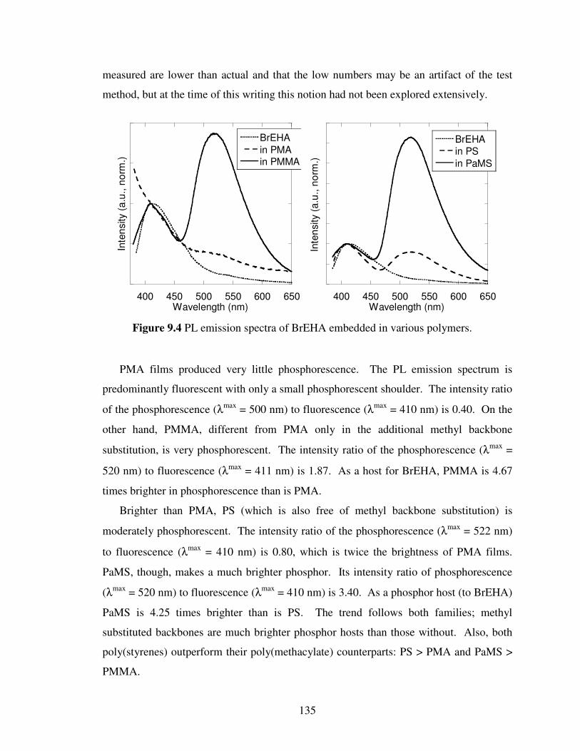
135
measured are lower than actual and that the low numbers may be an artifact of the test
method, but at the time of this writing this notion had not been explored extensively.
PMA films produced very little phosphorescence. The PL emission spectrum is
predominantly fluorescent with only a small phosphorescent shoulder. The intensity ratio
of the phosphorescence (λmax
= 500 nm) to fluorescence (λmax
= 410 nm) is 0.40. On the
other hand, PMMA, different from PMA only in the additional methyl backbone
substitution, is very phosphorescent. The intensity ratio of the phosphorescence (λmax
=
520 nm) to fluorescence (λmax
= 411 nm) is 1.87. As a host for BrEHA, PMMA is 4.67
times brighter in phosphorescence than is PMA.
Brighter than PMA, PS (which is also free of methyl backbone substitution) is
moderately phosphorescent. The intensity ratio of the phosphorescence (λmax
= 522 nm)
to fluorescence (λmax
= 410 nm) is 0.80, which is twice the brightness of PMA films.
PaMS, though, makes a much brighter phosphor. Its intensity ratio of phosphorescence
(λmax
= 520 nm) to fluorescence (λmax
= 410 nm) is 3.40. As a phosphor host (to BrEHA)
PaMS is 4.25 times brighter than is PS. The trend follows both families; methyl
substituted backbones are much brighter phosphor hosts than those without. Also, both
poly(styrenes) outperform their poly(methacylate) counterparts: PS > PMA and PaMS >
PMMA.
400 450 500 550 600 650
BrEHA
in PMAin PMMA
Inte
nsity (
a.u
., n
orm
.)
Wavelength (nm)400 450 500 550 600 650
BrEHA
in PS
in PaMS
Inte
nsity (
a.u
., n
orm
.)Wavelength (nm)
Figure 9.4 PL emission spectra of BrEHA embedded in various polymers.

136
Optical micrographs of these polymer-embedded phosphor systems shows select
regions of emission. Figure 9.5 shows an optical micrograph of a BrEHA/ PMMA films
under 365 nm UV light. The image shows what appear to be diffuse regions of green
phosphorescent emission that do not correlate to any feature in the bulk polymer, which
forms a homogenous film across the surface. On these view scales it is impossible to tell
whether this indicates that BrEHA is isolated into pockets separate from the polymer, but
it can be certain that there is some form of phase segregation happening in these blends.
The phosphorescent emission is non-homogenous.
From these observations the idea of entanglement is proposed. Figure 9.6 shows
schematically what is meant. In order for polymers to succeed as hosts to BrEHA or any
DHAE phosphor, they must share some structural similarity with the small molecule.
Really this is not unlike determining an adequate crystalline host for DHAE phosphor
design in Chapter 3. The polymer must be able to mix well with the chromophore in
order to seize its flexible substitutents and prevent vibrational losses.
Figure 9.5 Optical micrograph of BrEHA/PMMA film.

137
All of the four good host polymers (those shown in Figure 9.4) have some degree of
similarity to BrEHA. They all have vinyl backbones, which are like the alkyl
substitutents of BrEHA, and they all have relatively small pendants, methyl ester or
benzene. The first aspect is important because it allows the ehtylhexyl portions of
BrEHA to intertwine with the polymer backbones as they dry into their glassy state in
order for the chromophore to be held in place. Rigid-rod polymers such as poly(p-
phenylene ethynylenes) (PPE) and poly(p-phenylenes) (PPP) were attempted as hosts and
A B
D C
Figure 9.6 Schematic illustrating the idea of polymer entanglement. (A) BrEHA
liquid has great vibrational freedom so triplets relax non-emissively. (B) PPE has a
rigid backbone that does not entangle the alkyl substitutents of BrEHA. Triplets
relax by vibration here as well. (C) PVK has a flexible backbone, but its bulky
pendants prevent BrEHA molecules from getting close enough to become
entangled. (D) PaMS has a flexible, entangling backbone and small pendants.
BrEHA mixes well and the glassy polymer prevents vibrational freedoms. Triplets
emit strong phorphorescence.

138
failed to produce any phosphorescent emission. Their backbones are too unlike any part
of BrEHA, and their rigid structures prevent entanglement in any capacity as one cannot
tie a knot with sticks. The second aspect, small pendants, is important because it allows
the BrEHA molecule to get close enough to the polymer to achieve the substitutent
intertwining. Some larger-pendant polyvinyl polymers were used; poly(vinyl carbazole)
(PVK), poly(isopropyl methacrylate), and poly(benzyl methacrylate), and failed to
produce phosphorescence.7 These polymers have a proper backbone, but their larger
pendants essentially block it from interactions with BrEHA.
Another consideration regarding pendant choice is hinted at in the differences
between the poly(methacrylates) and poly(styrenes). Both poly(styrenes) perform better
than their poly(methacrylate) counterparts. This could be due to the structural similarity
between their phenyl substitutions and the aromatic structure of BrEHA. Methacylate, on
the other hand, shares no distinct similarity to BrEHA, which contains no methoxy or
ester feature. This may be creating enhanced solid-state interaction between the styrenes,
perhaps even some form of π-π interaction8 , 9
, that is absent in blends with the
methacrylates and is likely why those blends are brighter phosphors.
The most surprising finding from this study is the profound effect that the methyl
substitution makes. The two polymers presented without methyl substitutents on their
backbones, PMA and PS, are markedly less phosphorescent as hosts than those that do
have it, PMMA and PaMS. Though this structural difference is rather subtle it has a
profound effect on the brightness of phosphorescent emission from BrEHA, which means
that it must also have a profound effect on the efficiency of mixing between the polymer
and small molecule, work better to suppress vibrational freedom of the system, or both.
BrEHA has a branched alkyl chain that may exhibit a favorable solid-state interaction
with the additional branching of the methyl-substituted backbones. It is also possible that
the additional methyl group helps to fill voids near the polymer backbone, restricting
vibrational freedoms better than their methyl-free polymer brothers. Novel polymer
design may be a viable means to explore these ideas (perhaps a poly (styrene) with
methyl substitutions at both points in the polymer backbone) but has not yet been done.

139
9.3 Experimental
9.3.1 General Methods
All chemicals used were purchased from Sigma Aldrich and used without further
purification. Deuterated solvents for NMR were purchased from Cambridge Isotope
Laboratories. Proton NMR was conducted on a Varian Mercury 300 using CDCl3 solvent
with chemical shifts identified relative to 0.05 v/v% tetramethylsilane standard (0.00
ppm). Anhydrous tetrahydrofuran was generated by refluxing over sodium metal and
benzophenone collected only from deep purple solution.
UV Absorption measurements were collected using a Varian Cary 50 Bio
spectrometer with a solution samples held in a quartz cuvette. PL emission, excitation,
and quantum yield data were collected using a Photon Technologies International (PTI)
Quantamaster system equipped with an integrating sphere. Optical micrographs are
collected using an Olympus BX51 optical microscope equipped with a Mercury lamp UV
light source and Olympus DP71 color digital camera. Polymer film preparation is
described in the text above.
9.3.2 Synthesis and Characterization
Synthesis of 1,4-dibromo-2,5-di((2-ethylhexyl)oxy)benzene (BrEH) 2,5-
dibromohydroquinone (1equiv.) is loaded into a 2-neck glass round bottomed flask along
with 1-bromo-2-ethylhexane (2.5 equiv.) and dimethylformamide (ca. 1 ml / g reagent).
Potassium carbonate (3 equiv.) is added and the reaction is stirred at 75oC for 24 hours.
Scheme 9.1 Synthetic route to BrEH6A.
OHHO
Br
Br
Br
DMF, 75oC,
24 h
OEHHEO
Br
Br
+
(= EH)
BrEH, 55%
K2CO3
OEHHEO
Br
Br
1. 1x nBuLi, THF,
-78oC, 1h
2. DMF, 23oC, 3h
OEHHEO
CHO
Br
BrEHA, 15%

140
The reaction is cooled, vacuum filtered, and rotavaped at 80oC to remove solvents
(DMF). The products are then purified through column chromatography using a hexanes
eluent. A clear liquid is collected at a yield of 55%. For BrEH, 1H NMR (300 MHz,
CDCl3): 7.10 (s 2H), 3.85 (d 4H), 1.77 (m 2H), 1.51 (m 8H), 1.36 (m 8H), 0.95 (m 12H).
Synthesis of 4-bromo-2,5-di((2-ethylhexyl)oxy)benzaldehyde (BrEHA) BrEH (1
equiv.) is loaded into a two-neck round bottomed glass flask and vacuum purged with
argon three times. Anhydrous tetrahydrofuran is added by syringe (ca. 25 ml solvent / g
Br6) and the vessel is placed into a bath of dry ice and 2-propanol (-78oC). n-
Butyllithium (1 equiv.) is added dropwise via syringe and the reaction is stirred at -78oC
for 1 hour. Anhydrous DMF (4 equiv.) is then added and the reaction is allowed to warm
to 23oC over three hours. The reaction is quenched carefully with water and extracted
with diethylether. The organic layer is collected and dried over MgSO4 before being
filtered and rotovaped to remove solvents. Purification is done by column
chromatography with ethylacetate:hexane (1:30) eluent followed by successive
recrystallizations from methanol and acetonitrile at 23oC. A colorless liquid is collected
at yields of 15%. For Br6A, 1H NMR (300 MHz, CDCl3): δ 10.42 (s 1H), 7.33 (s 1H),
7.24 (s 1H), 3.93 (t 4H), 1.77 (m 2H), 1.50 (m 8H), 1.32 (m 8H), 0.94 (m 12H).
9.4 Conclusions
Common polymers may be suitable replacements to crystalline host materials for the
activation of DHAE-style phosphors. Efficient triplet-generating chromophores such as
BrEHA, a member of the BrnA family, can become brightly phosphorescent when
embedded into certain glassy polymers. This effect can be strong even if the
chromophore is highly non-crystalline. BrEHA is a liquid yet becomes brightly
phosphorescent in certain polymers at ambient temperatures. Glassy polymers, well
mixed with DHAE-style small molecule chromophores, can prevent vibrational freedom
of the chromophore leading to triplet emission that is dominant over non-emissive
relaxation. If the polymer constricts the chromophore efficiently, phosphorescent
emission is surprisingly strong.

141
The critical concept to choosing a good polymer host is the idea of entanglement. In
order for the two species to mix well the polymer must have two critical features: a
flexible backbone that is structurally similar to the substitutents of the chromophore, and
small pendants that do not shield the backbone from the small molecule. If these two
conditions are met, the small molecule’s substitutents (alkoxy as presented here) can
entangle with the polymer backbone, which imparts glassy properties to the chromophore
and restricts vibration. This effect can be enhanced if the backbone has a more space-
filling structure, such as additional methyl substitutents, and if the pendants have any
favorable interaction with the small molecule, such as π-π interactions.
By activating the phosphorescence of DHAE phosphors in non-crystalline and
disordered systems we have removed one of the strict requirements of the DHAE design
principle: perfect crystal order. This widens the design of metal-free organic phosphors
even further and opens their use to a wider variety of applications. Also, the many
desirable aspects of polymeric systems; process-ability, homogeneity, dope-ability, etc.,
are now available to DHAE phosphors. This work also holds promise of a true polymeric
metal-free organic phosphor suitable for the fabrication of optoelectronic and optical
biological devices.10,11,12
This work may also be expanded to improve the phosphorescence brightness by
improved polymer-chromophore interaction through secondary bonding.13,14
Perhaps by
designing a polymer/chromophore pair that exhibits complementary groups for strong
hydrogen bonding, better mixing and brighter emission can be achieved.

142
9.5 References
1 O. Bolton, K. Lee, H.-J. Kim, K.Y. Lin, and J. Kim Nature submitted 2009.
2 O. Bolton, S. Jeon, and J. Kim manuscript in progress.
3 R. E. Harding, S.-C.Lo, P. L. Burn, and I.D.W. Samuel, Org. Electron. 2008, 9, 377.
4 T. Sajoto, P. I. Djurovich, A. Tamayo, M. Yousufuddin, R. Bau, and M. E. Thompson,
Inorg. Chem. 2005, 44, 7992. 5 W.Y. Huang, S. Matsuoka, T.K. Kwei, and Y. Okamoto Macromol. 2001, 34, 7166.
6 D.A.M. Egbe, L.H. Nguyen, H. Hoppe, D. Muhlbacher, and N.S. Saricifci Macromol.
Rapid Comm. 2005, 26, 1389. 7 Some very weak phosphorescence was occasionally detected for the methyl acrylates
listed here, but results were inconsistent and much weaker than the featured polymers
listed in Figure 9.4. 8 K. Li, L. Guo, Z. Liang, P. Thuyagarajan, and Q. Wang J. Polymer Sci. A: Polymer
Chem. 2005, 43, 6007. 9 U.H.F. Bunz et al Chem. Mater. 1999, 11, 1416.
10 J. H. Burroughes et al 1990, 347,539.
11 B.J. de Gans, P.C. Duineveld, and U.S. Schubert Adv. Mater. 2004, 16, 203.
12 J. Peet, A.J. Heeger, and G.C Bazan 2009, 42, 1700.
13 D.C. Sherrington and K.A. Taskinen Chem. Soc. Rev. 2001, 30, 83.
14 C.R. South, C. Burd, and M. Weck Acc. Chem. Rev. 2007, 40, 63.

143
Chapter 10
Conclusions
10.1 Summary
The purpose of this thesis is to explore novel metal-free organic phosphor design
through the design principle named the Directed Heavy Atom Effect, DHAE. As the
parallel fields of organic materials and phosphorescent materials have been experiencing
great surges in interest, they have been united only in a relatively small subset of
organometallic compounds.1,2
The DHAE principle, as is demonstrated in this work,
provides a means to create new metal-free organic phosphors that are bright, robust,
simple, and can be designed to emit specific colors, exhibit unique materials properties,
and possess desired chemical functionalizations.
Phosphorescent materials are desirable in various applications because they emit from
triplet states. Because they can emit from any of the three possible triplet states, they are
more efficient emitters in light emitting devices than fluorescent emitters, which emit
from only one.3 Also, the long-living triplet states are believed to enhance exciton
diffusion lengths in solar cells, allowing for the design of thicker absorbing layers and
higher efficiency devices.4 If these long-living triplets are allowed to emit they produce
signals that are easily distinguished from short-living fluorescence, which is useful in
certain detection schemes.5 Triplets are also uniquely susceptible to quenching by other
triplets materials, such as oxygen, giving them special use in biological sensing as well.6
With so many emerging applications for phosphorescent materials, the need for a
versatile design principle to make new phosphors is critical. Previous phosphor design
was limited to inorganic materials (mostly ceramics) and a small family of
organometallic compounds.7 The DHAE principle provides the ability to escape these
limitations and design bright phosphors that are fully organic and metal-free.

144
The DHAE principle succeeds by combining two critical phenomena: the heavy atom
effect and halogen bonding. The heavy atom effect occurs when a large atom, usually a
halogen, enhances intersystem crossing in another molecule in close proximity. The
large nucleus of the heavy atom enhances spin-orbit coupling, mixing singlet and triplet
states to better produce the later. The DHAE principle enhances this through halogen
bonding, which is a non-covalent interaction akin to hydrogen bonding that brings
halogens exceptionally close to nucleophilic atoms. If the nucleophile is the carbonyl
oxygen atom of a triplet allowing aromatic ketone, excellent triplet generation and bright
phosphorescence can be achieved.
DHAE phosphors are brightest in crystal states, where halogen bonding is strongest
and tight packing prevents vibrational losses that are otherwise very competitive with
triplet emission. Further quenching effects can be eliminated by the introduction of a
host material. A host material is structurally very similar to the phosphorescent
chromophore but is optically non-interfering. It acts as an optically inert matrix that
exhibits the same halogen bonding as the chromophore but also effectively prevents self-
quenching by isolating each chromophore molecule in the crystal (co-crystal, as it is).
The most efficient DHAE phosphors presented here are based on a 4-
bromobenzaldehyde chromophore coupled with a 1,4-dibromobenzene host. This is the
case for nearly every chromophore/host pair in this work. The reasons that
benzaldehydes work so well are both the minimal substitution at the carbonyl carbon (all
other aromatic ketones contain larger moieties at this site) and the excellent similarity in
volumetric size between the aldehyde group and the bromine atom. The former makes
access to the aldehyde, for halogen bonding, more favorable while the later makes
cocrystallization much more favorable.
Efficient cocrystallization is critical to achieving high quantum yields (QY) in
crystalline DHAE phosphors. As chapter 4 demonstrates, low concentrations of the
chromophore (relative to the host concentration) leads to inefficient inclusion into the
cocrystal and, thus, low QYs. Likewise, large amounts of chromophore lead to self-
quenching by excimer formation and triplet-triplet annihilation. Ideal mixes of
chromophore and host are seen at concentrations of one-to-ten weight percent
chromophore. QYs of cocrystals Br1A/Br1, Br6A/Br6, and BrE6A/BrE6, for examples,

145
average 55 - 60% and have been measured as high as 68%. These are the highest QYs
measured for all DHAE phosphors presented here.
The DHAE principle can be used to design organic phosphors of different colors by
altering the electron density at the core aromatic unit of the chromophore. As chapter 5
shows, this approach allows for both fine and coarse color tuning. By altering the
halogen on the chromophore phosphorescent emission is red-shifted in discrete 5 nm
steps from chlorine to bromine to iodine. Removing the halogen altogether, replacing it
with hydrogen, shifts the emission roughly 30 nm to the blue, but also makes
cocrystallization difficult because of the pronounced difference in chromophore/host
structural agreement. Changing the electron donating properties of the chain substituents
allows for coarse color tuning. The alkyl substituents of BrAlkyl6A/BrAlkyl6 give their
Br
Aro
matic
H
O
A
Br Br
Aro
matic
B
Figure 10.1 Schematic representation of the DHAE design principle. (A) The
chromophore: a halogenated aromatic aldehyde. (B) The host: a di-halogenated
analog to the chromophore. The aldehyde group is replaced with a halogen atom.
(C) Crystals of pure chromophore: the heavy atom effect is directed to the
aldehyde by halogen bonding, greatly increasing intersystem crossing.
Phosphorescence is emitted though self-quenching is prevalent and QY is modest.
(D) Cocrystals of chromophore and host, with a majority of host molecules: crystal
packing exhibits the same halogen bonding as pure chromophore crystals but the
chromophores are now diluted, preventing self-quenching. The phosphorescent
QY is extremely high.
D
Halogen bonding Halogen-Halogen Interaction
C
Halogen bonding

146
cocrystals a blue emission while the alkoxy substituents of Br6A/Br6 yield green.
BrS6A/BrS6 have thiol ethers that lead to red-shifted yellow phosphorescence.
Np6A/Np6 cocrystals have alkoxy substitution but emit orange phosphorescence because
their central chromophore is extended from the benzene ring of Br6A to a naphthalene
ring, which increases the electron density even more than chain alterations. These
demonstrate not only successful application of the general design principles of DHAE,
that a brominated aromatic aldehyde cocrystallized with its dibromo variant emit
phosphorescence, but that it can be tuned to alter the emission color as well.
In chapter 6 further investigation of the phosphorescent emission from crystals of
pure Br6A reveal the novel phenomenon of delayed phosphorescence.8
Delayed
emission occurs when lower-energy excited states are thermally populated into emissive
states. This has been observed many times for fluorescence, but until now it has not been
seen for phosphorescence, presumably because it would require up-conversion from a
normally highly-quenching intermolecular state.9 Once excited, crystals of Br6A relax to
a triplet excimer lower in energy than T1. With sufficient heat, which is ample at room
temperature, electrons in this excimer state are raised to T1, where they emit in the exact
same spectrum as normal, prompt phosphorescence. This emission is only
distinguishable from prompt phosphorescence because it occurs at a much slower rate
and it is completely absent at low temperature. This finding is noteworthy because it
represents a reclamation of emissive triplets from excimer states, normally considered a
wholly quenching state.10
This holds promise for enhancing efficiencies from organic
light emitting devices where excimer formation is common and detrimental.
Br1A/Br1, the smallest member of the featured BrnA/Brn family of DHAE
phosphors, exhibits simple synthesis, high QYs, and unique microstructures grown by
sublimation. As explained in chapter 7, Br1A and Br1 are extremely simple DHAE
phosphors that can be synthesized with fewer impurities and in larger batches than any
others in the BrnA/Brn family. Dropcast samples exhibit QYs as high or higher than
Br6A/Br6 cocrystals with some measured as high as 62%. These compounds are also
about 66% smaller than Br6A/Br6 making their cocrystals much denser and appearing
much brighter. Perhaps most intriguing, Br1A and Br1 sublime readily to form
monodisperse needle/rod-shaped cocrystals whose sizes appear to be controllable by
147
sublimation time. These crystals are very bright, exhibit apparent anisotropic emission,
and hold promise for the design of metal-free organic phosphorescent metamaterials.
Extending the usefulness of DHAE phosphors involves adding useful functionality to
the crystals so that they can be designed for use in any application desired. Chapter 8
shows one such functionalized material in BrE6A/BrE6 cocrystals. These compounds
have ester functionality at the ends of their alkoxy substituents. They cocrystallize very
well and achieve QYs on par with Br6A/Br6 cocrystals while actually out-performing
their efficiency them at higher chromophore concentrations. The ester functionality does
not affect the crystal packing so halogen bonding is still dominant, yet it offers the
possibility of post-crystallization de-protection to add carboxylic acid functionality to the
cocrystals. This holds promise for attaining useful chemical functionalities in DHAE
materials by demonstrating one approach to achieving phosphors that contain functional
groups that may otherwise interfere with the desired halogen-bonding crystal motif.
A final study demonstrates that DHAE-style phosphors hold promise for metal-free
organic phosphorescence even in the absence of crystal order by instead being embedded
into select polymers. Chapter 9 shows that mixing DHAE chromophores into polymers
that do not have large pendants and have backbones whose structures are similar to the
chain substituents of the chromophore can activate phosphorescent emission. When these
conditions are met, the polymer effectively entangles the chromophore to provide the
rigidity usually imparted by the crystal. This entanglement prevents vibrational freedom
of the chromophore so that triplets are not lost to internal conversion. These systems
extend the usefulness of DHAE-style phosphors even further to include non-crystalline
materials or those that do not crystallize with strong halogen bonding.
In summary, the DHAE design principle removes the existing limitations on organic
phosphor design. This work has shown how bright metal-free organic phosphors can be
synthesized through a few simple design requirements: aromatic ketones and halogen
bonding. The potential to tune the optical, material, and chemical properties of these
phosphors is clearly demonstrated as is a successful approach to reducing the halogen
bonding/crystalline requirement altogether. The DHAE principle promises a paradigm
shift in the field of phosphorescent materials.

148
10.2 Future Considerations
The work presented here is only the very beginning of DHAE phosphor research.
This phenomenon was discovered through serendipity and most of the time dedicated to
it thus far has been to explore its requirements and make small alterations to the first
phosphor discovered. Luckily the BrnA/Brn family of phosphors have been ideal for
study because they are bright and easy (and economical) to synthesize. Thus, they were
the focus of this work. Uncountable lists of new phosphors and work to be done remains
in the field of DHAE phosphors.
Work to integrate these phosphors into OLEDs has begun in earnest, though progress
has been slow. Unlike the organometallic phosphors that are currently dominating the
field, DHAE phosphors operate best when highly crystalline and sublime at relatively
low temperatures. These aspects make it difficult to simply substitute DHAE phosphors
into the fabrication techniques of organometallic OLEDs. Achieving bright electro-
phosphorescence from DHAE-based devices seems achievable given the high PL QYs
observed but it may require entirely new device design and/or fabrication technique.
Great promise exists, however, to shorten this process as new DHAE materials with
improved and additional functionalities, such as better carrier mobility or higher
sublimation temperatures, may accelerate these efforts.
There is also the possibility of using DHAE compounds as efficient triplet sustaining
materials to improve the exciton diffusion lengths in organic photovoltaics.
Organometallic phosphorescent compounds, “triplet materials,” have been employed to
this effect with mixed success.11
DHAE phosphors have the advantage of much longer
living triplets (as evidenced by the long, millisecond phosphorescent lifetimes). This can
enhance exciton diffusion by allowing the excited states more time to diffuse. The idea
of using DHAE materials in this way is especially interesting because it does not require
that the triplets emit (in fact it would prefer that they did not), which may make the
requirements of strict crystal packing less necessary.
A final future application for which DHAE phosphors may be uniquely suited is in
sensor design. Aside from those mentioned in Chapter 1, emissive lifetime and oxygen-
quenching approaches, the unique conformational aspect of DHAE phosphorescence may
be useful for sensing. This report has shown how the heavy atom effect is so greatly
149
enhanced when directed by halogen bonding. It may be possible to design benzaldehyde
and halogen pairs into compounds that exhibit other forms of conformational recognition,
such as in numerous biological compounds. If the conformational recognition is coupled
with the formation of a DHAE halogen bond, a strong phosphorescent signal may be
generated. Given the high sensitivity of photonic detection, this may offer a way to turn
imperceptible biological recognitions into measurable signals. It would also be
detectable on a phosphorescent timescale, which would have the added benefits of
improved signal-to-noise ratios and measurement by dynamic spectroscopy.

150
10.3 References
1 M.A. Baldo, M.E. Thompson, and S.R. Forrest Pure Appl. Chem. 1999, 71, 2095.
2 A. Kohler, J.S. Wilson, and R.H. Friend Adv. Mater. 2002, 14, 701.
3 M.A. Baldo, D.F. O’Brien, Y. You, A. Shoustikov, S. Sibley, M.E. Thompson, and S.R.
Forrest Nature 1998, 395, 151. 4 Y. Shao and Y. Yang Adv. Mater. 2004, 17, 2841.
5 A.P. de Silva, H.Q.N. Gunaratne, T. Gunnlaugsson, A.J.M. Huxley, C.P. McCoy, J.T.
Rademacher, and T.E. Rice Chem. Rev. 1997, 97, 1515. 6 W.L. Rumsey, J.M. Vanderkooi, and D.F. Wilson Science 1998, 241, 1649.
7 E. Baranoff, J.-H. Yun, M. Graetzel, and Md.K. Nazeeruddin J. Organometallic
Chem.2009, 694, 2661. 8 This is not to be confused with another phenomenon known as “delayed
phosphorescence,” which is actually dynamically-resolved emission from the Tx,Ty,
and Tz triplet states at low temperatures. An example: J. Schmidt, D.A. Antheuni, and
J.H. Vanderwa Mol. Phys. 1971, 22, 1. See Chapter 6. 9 B. Hu, L.A. Yan, and M. Shao Adv. Mater. 2009, 21, 1500.
10 M.A. Slifkin and A.O. Al-Chalabi Chem. Phys. Lett. 1974, 29, 110.
11 F. Guo, Y.-G. Kim, J.R. Reynolds, and K.S. Schanze Chem. Comm. 2006, 1887.