the development of a thin-film rollforming process for
TRANSCRIPT

The Development of a Thin-Film Rollforming Process for
Pharmaceutical Continuous Manufacturing
by
Ryan Slaughter
Submitted to the Department of Mechanical Engineeringin partial fulfillment of the requirements for the degree of
Master of Science in Mechanical Engineering
at the
MASSACHUSETTS INSTITUTE OF TECHNOLOGY
MASSACHUSETTS INS EOF TECHNOLOGY
APR 16 2013
LIBRARIES
@ Massachusetts
February 2013I uteoe 2 0 3
Institute of Technology 201 3. All rights reserved.
Author .................................. ... . ...........Department of Mechanical Engineering
January 18, 2013
Certified by ..................... .... ................Jung-Hoon Chun
Professor of Mechanical EngineeringThesis Supervisor
Accepted by.............. . . . . . .-.-.-.-. .-.-. .-.-.-- - -
David E. HardtProfessor of Mechanical Engineering
Chairman, Department Committee on Graduate Students

The Development of a Thin-Film Rollforming Process for
Pharmaceutical Continuous Manufacturing
by
Ryan Slaughter
Submitted to the Department of Mechanical Engineeringon January 18, 2013, in partial fulfillment of the
requirements for the degree ofMaster of Science in Mechanical Engineering
ABSTRACT
In this thesis, a continuous rollforming process for the folding of thin-films was proposed
and studied as a key step in the continuous manufacturing of pharmaceutical tablets. HPMC
and PEG based polymeric thin-films were considered for this application. An experimental
apparatus was designed and developed to test the folding of thin-films. The experimental
apparatus was designed in a modular fashion to facilitate testing of various process pa-
rameters. Analysis was carried out for the folding operations, based on which two folding
strategies were proposed - (i) without scoring and (ii) with scoring. The first strategy relies
on elastic deformation of the thin-films, whereas the later depends on localized, plastic de-
formation caused by the scoring geometry. From the experiments on folding we identified
three regimes of process operation namely: insufficient scoring, appropriate scoring, and
excessive scoring. The implications of different levels of scoring were observed and under-
stood carefully for the scoring and folding operation. Practical guidelines were developed
for carrying out folding successfully and the scope of future work was discussed.
Thesis Supervisor: Jung-Hoon ChunTitle: Professor of Mechanical Engineering
2

0.1 Acknowledgments
To begin, I would like to thank my advisor, Professor Jung-Hoon Chun, who allowed me
the incredible opportunity to work in his research lab and provided me with indispensable
supervision and guidance throughout the past few years. Without his personal support,
concern, and truly extraordinary patience, I could not have completed this work. Thank
you.
I also offer my sincere thanks to the Department of Mechanical Engineering, my LMP
lab mates, and other MIT staff-most notably Dr. Nannaji Saka, David Dow, Professor
David Hardt, Professor Sanjay Sarma, Professor Martin Culpepper, Professor James H.
Williams Jr., Dr. Dedric Carter, Sandy Tenorio, Julian Green, Leslie Regan, Peggy Garlick,
Won Kim, Aron Blaesi, Norma Ellis, and Craig Evitts-for their advice and encouragement
through my undergraduate and graduate studies at the Institute.
Finally, I must express my overwhelming gratitude and love for my Mom, Dad, family,
and dear friends who, despite my best efforts, have remained with me always, sustaining
an unwavering love that continues to illuminate my life with meaning and purpose.
I regretfully apologize to the numerous family members, friends, and past teachers
that I did not mention specifically for their support of my efforts-but please know that
I appreciate you all and find it truly remarkable that I have been able to forge so many
fulfilling relationships with such a wonderful and diverse group of people.
Thank you all.
3

Contents
0.1 Acknowledgments . . . . . . . . . . . . . . . . . . . . . . . . . . . . . .
1 Introduction
1.1 Importance of Continuous Manufacturing in Pharmaceutical Production .
1.2 Thin-Film Preparation . . . . . . . . . . . . . . . . . . . . . . . . . . . .
1.3 Rollforming as a Pharmaceutical Manufacturing Process . . . . . . . . . .
1.4 O rganization . . . . . . . . . . . . . . . . . . . . . . . . . . . . . . . . . .
2 Analysis of Rollforming Processes
2.1 Rolling and Folding . . . . . . . . . . . . . . .
2.1.1 Rollforming of Polymeric Thin-Films
2.1.2 Effect of Scoring on Folding Process
2.1.3 Local Yielding . . . . . . . . . . . . .
3 Design of the Experimental Apparatus
3.1 Mechanical Characterization of the Thin-Films
3.2 Functional Requirements . . . . . . . . . . . .
3.3 Machine Components . . . . . . . . . . . . . .
4 Experimental Results
4.1 Folding Experiments . . . . . . . . . . . . . . . . . . . . . . . . . . . -
5 Conclusions and Future Work
4
19
. . . . . . . . . . . . . . - 1 9
. . . . . . . . . . . . . . . 1 9
. . . . . . . . . . . . . . . 20
. . . . . . . . . . . . . . . 22
28
. . . . . . . . . . . . . . . 28
. . . . . . . . . . . . . . . 30
. . . . . . . . . 30
37
41
49
3
8
8
11
15
18
List of Figures
Thin-film tableting process overview . . . . . . . . . . . . .
Example of a chemical formulation for thin-film preparation.
Example of solution casting for thin-film making. . . . . . .
Chemical formula of PEG. . . . . . . . . . . . . . . . . . .
Chemical formula of HPMC. . . . . . . . . . . . . . . . . .
Sheet undergoes rollforming. . . . . . . . . . . . . . . . . .
Traditional rollforming . . . . . . . . . . . . . . . . . . . .
. . . . . . . . 11
. . . . . . . . 13
. . . . . . . . 14
. .. .. .. * 14
. . . . . . . . 15
. . . . . . . . 16
. . . . . . . . 17
2-1 Sheet folding by rollforming process. . . . . . . . . . . . . . . . . . . . .
2-2 Simplified Euler bending model. . . . . . . . . . . . . . . . . . . . . . . .
2-3 Euler beam bending model dimensionless ligament thickness vs. curvature
ratio. . . . . . . . . . . . . . . . . . . . . . . . . . . . . . . . . . . . . . .
2-4 Effect of notch angle on stress concentration factors for a thin beam ele-
ment in bending with a v-shaped notch on one side. . . . . . . . . . . . . .
2-5 Bending of a thin beam element with a U-shaped notch on one side.....
2-6 Dimensionless ligament thickness vs. dimensionless stress, based on stress
concentration analysis for E = 150MPa, cy = 12MPa, r = 11pm, H = 132pm.
Zwick universal tester used for thin-film material property characterization.
Characteristic stress-strain curve for placebo thin-film. . . . . . . . . . . .
Entrance rollers to the rollforming station. . . . . . . . . . . . . . . . . . .
Folding rollers for 1-fold stand. . . . . . . . . . . . . . . . . . . . . . . . .
Folding rollers for 3-fold stand. . . . . . . . . . . . . . . . . . . . . . . . .
CAD model of a rollforming fold stand. . . . . . . . . . . . . . . . . . . .
20
21
23
25
26
27
29
29
30
31
31
32
5
1-1
1-2
1-3
1-4
1-5
1-6
1-7
3-1
3-2
3-3
3-4
3-5
3-6

3-7 Folding stand electric motor and drive schematic. . . . . . . . . .
3-8 CAD model of the rollforming final traction stand. . . . . . . . .
. . . 34
. . . 35
4-1
4-2
4-3
4-4
4-5
4-6
4-7
4-8
4-9
4-10
4-11
4-12
4-13
4-14
4-15
6
Folding stand unit. . . . . . . . . . . . . . . . . . . . . . . . . . . . . . . 38
Folding disc profile without scoring feature. . . . . . . . . . . . . . . . . . 38
Folding disc profile with scoring feature. . . . . . . . . . . . . . . . . . . . 39
Film geometry along scoreline. . . . . . . . . . . . . . . . . . . . . . . . . 39
Folding regime identified for scoring. . . . . . . . . . . . . . . . . . . . . 40
Experimental apparatus assembled with non-scoring discs, view 1 . . . . . 42
Experimental apparatus assembled with non-scoring discs, view 2 . . . . . 42
Thin-film undergoing folding process without scoring marks. . . . . . . . . 43
Experimental apparatus assembled with scoring discs, view 1 . . . . . . . . 44
Experimental apparatus assembled with scoring discs, view 2 . . . . . . . . 45
Scored thin-film exiting final traction rollers . . . . . . . . . . . . . . . . . 45
Folding with partial scoring and drifting defects . . . . . . . . . . . . . . . 46
Scored thin-film output specimen. . . . . . . . . . . . . . . . . . . . . . . 47
Microscopic image of scoreline with w = 69.8pm, ds = 34.9pm. . . . . . . 47
Microscopic image of scoreline with w = 33.3pm, ds = 16.7pm. . . . . . . 48

List of Tables
1.1 Key properties for pharmaceutical tablets . . . . . . . . . . . . . . . . . . 12
3.1 Material list for machine components. . . . . . . . . . . . . . . . . . . . . 36
7

Chapter 1
Introduction
1.1 Importance of Continuous Manufacturing in Pharma-
ceutical Production
Manufacturing process design and implementation in the pharmaceutical industry is rapidly
evolving from batch processing methods to more efficient continuous processing protocols
under certain circumstances. It may seem surprising that the pharmaceutical industry has
not developed continuous methods for product design, given the industry's maturity and
fiscal strengths, but the traditional tablet is a commonly accepted drug delivery vehicle.
The global pharmaceutical industry is slow to shift from the traditional batch tablet
design, because current methodology offers precise dosing, ease of handling, and a long
shelf life [?]. However, examining some of the advantages of continuous sub-process de-
velopment in comparison to similar batch-based methods can offer a viable solution to the
conventional and complicated chain of solid powder batch formation.
The manufacturing of tablets involves two sub-processes: an upstream process, where
chemical production is the focus, and a downstream process , where mechanical forming is
the focus.
The primary output of the upstream chemical processes is the Active Pharmaceutical
Ingredient (API). The upstream process is the collection of chemical reactions necessary
to produce the API, which is the real drug component of a tablet. Medically value-added
8

API is compounded with raw chemical materials, which have no pharmaceutical effect,
throughout the chemical synthesis process and then subsequently purified via crystalliza-
tion. Tablets are formed at the downstream process by annexing adducts, such as excipients
and solvents, to the APIs. An excipient is a pharmaceutically inert substance that acts as a
carrier of APIs. Excipients are comprised of dilutents for size and volume control, disin-
tegrating agents for absorption in the body, binders for adhesion, glidants for lubrication,
stabilizers for shelf-life control, etc. The bulk and surface characteristics of the API solid
powder are homogenized by the granulation and milling processes. This improves powder
flowability of the transfer process and makes tablet compaction and binding easier. There-
after, API powder is blended with excipient powder and then compacted at the tablet press
to become the final solid tablet dosage form.
This complicated chain of batch operations has been the convention of the pharma-
ceutical industry since the late 19th century. However, this conventional methodology has
intrinsic problems, specifically in the area of solid powder handling. Homogeneous mixing
of API powder with excipient powder is difficult to accomplish during the blending pro-
cess. Inefficiency in the blending protocol can lead to a non-uniform distribution of API
content and density in the tablets. Moreover, the batch-based tablet manufacturing process
is expensive, inefficient and has a longer production time in comparison to other processes
in highly competitive industries, primarily because material flow is not continuous between
its sub-operations. In addition to these factors, it is difficult to maintain flexible control on
output volume when considering unpredicatable fluctuations in market demand, and when
a new drug is developed, a batch-based manufacturing process requires excessive time and
expense for the re-design and scale-up of the required manufacturing facility.
The batch-based tablet manufacturing process has been used in pharmaceutical factories
on a global scale for over one hundred years, because until now, pharmaceutical companies
have made enough profits on new drug designs to offset the problems associated with the
downstream processing of the drugs. However, as the industry has continued to mature
and grow in competitiveness, it has become more difficult and costly to discover and de-
velop patent-protectable blockbuster drugs, such as those required to treat the ailments of
hypertension, diabetes, heartburn, and high cholesterol medicines [?]. Hence, there is an
9

imminent push toward more efficient, timely, and cost-effective manufacturing processes
in the pharmaceutical industry. Furthermore, competition in the generic drug market is
quickly ramping up, because of rising companies in developing countries. Once a new
drug patent expires, virtually any pharmaceutical company can develop a generic version
of it. Only companies with the ability to produce the same drug at a lower cost will sur-
vive in this highly competitive industry, and for this reason, a more efficient manufacturing
process is becoming increasingly important.
Thus, pharmaceutical companies are actively seeking more efficient and cost-effective
methods of manufacturing their drugs. Motivated by these concerns, a research project
has been launched at the Novartis-MIT Center for Continuous Manufacturing (CCM) with
the aim of converting the conventional batch-based tablet manufacturing process into a
continuous one. This research has the potential to change the pharmaceutical manufactur-
ing paradigm by solving the problems originating from batch-processed and powder-based
tablets. A continuous tablet manufacturing process can be realized by replacing solid pow-
der handling with co-processing of APIs and excipients in a liquid-phase solution. Blend-
ing of APIs, excipients, and solvents in the liquid-phase improves homogeneity of blends.
A continuous tablet manufacturing process can be accomplished by avoiding granulation
operations, which are an essential part of solid powder handling, and the primary cause
of discontinuous material flow. The continuous tablet manufacturing process has the fol-
lowing advantages as compared with the conventional batch-based manufacturing process:
(a) uniform and rapid blending of API and excipients, (b) cost-saving, (c) fast production
speed and high yield, (d) real-time quality inspection, (e) fast market introduction of new
drugs (f) flexible output control and (g) easy automation.
When tablets are manufactured via liquid-phase solution of APIs, excipients, and sol-
vents, one of the challenging issues is drying, that is, how to remove adequate amounts of
solvents rapidly. In the general drying process, such as hot plate or hot air drying, the sur-
face is dried and solidified first and then acts as a barrier obstructing solvent mass transfer.
Because of this negatively compounding effect, it is difficult to get rid of solvents remain-
ing in the inner part of the material. Solvent casting of thin films is one strategy to solve
this potential drying challenge, since the process enlarges the surface area and reduces the
10

Thin Film
Foldng
Substrate Roller Compression
CastingDrying I
Liquid Solution
Pressure Upper Punch
C gCuttingi
Die
Pressure Lower Punch
Compaction
Tablet
Figure 1-1: Thin-film tableting process overview.
required solvent diffusion length, so that solvent evaporation may occur more quickly and
completely. Polymer films have not previously been investigated for buccal delivery [?],
but clearly, solvent-cast thin films hold great promise for the continuous process manufac-
turing of tablets.
A folding operation is a potential candidate for producing tablets from the solvent-cast
thin films. Thin-film sheets, which are cast on to a non-sticking substrate from the homo-
geneous liquid solution of APIs, excipients, and solvents, may be formed into accordion-
like folds by this process. The folded thin-films could then be further treated, utilizing
roller compression, cutting, and final shape compaction, to become tablets as shown Fig-
ure reffig:processoverview. These tablets will satisfy the requirements listed in Table 1.1
[?, ?, ?, ?].
1.2 Thin-Film Preparation
The thin-films were prepared by solvent casting using a casting apparatus. The key ingre-
dients of the chemical formulation for film making are as follows:
11

Table 1.1: Key properties for pharmaceutical tablets
Mechanical Properties: Hardness, Friability
Release Profile: Disintegration, Dissolution Rate
Uniformity Content: Density, Shape, Surface Uniformity
Stability: Mechanical, Thermodynamic, Chemical Stability
General: Appearance Biconvex Shape
(a) Active Pharmaceutical Ingredient (API) - the real drug substance for the medication,
(b) Excipient - a pharmacologically inactive substance used as a carrier for API,
(c) Plasticizer - a pharmacologically inactive substance that plays a key role in altering
the mechanical properties and bonding behaviors of the films,
(d) Solvent - to aid in dissolving and mixing of the API, Excipient and Plasticizer to
form a homogeneous solution. Note that the API, Excipient, Plasticizer and Solvent must
all be compatible while in the solution.
In this thesis, we worked with placebo formulations, that is, thin-films without any
active drug substance, to ameliorate any potential handling or safety issues. The placebo
films were carefully formulated and processed to have mechanical properties similar to
those of an API-based formulation.
In this study, we have employed hydroxypropyl methylcellulose, HPMC e3 and e15, as
the primary excipients and used polyethylene glycol, PEG-400, as a plasticizer. Distilled
water and ethanol were used as solvents.
The thin-film making procedure was performed as described below:
(a) The properly measured amounts of base polymer and excipient are dissolved in
12

Ethanol,
(b) To the above solution, water and PEG-400 are added,
(c) API is finally added.
The solution is stirred for approximately 24 hours, thereby ensuring homogenous mix-
ing. After solution is prepared and mixed it is allowed to stand alone for several hours to
allow for settling. It is then degassed in a vacuum chamber in order to remove gas bubbles
that would negatively impact the resulting thin-film. Figure 1-2 shows prepared solution.
Figure 1-2: Example of a chemical formulation for thin-film preparation.
Preparation of thin-films was carried out using a casting apparatus comprised of an
adjustable-height knife, to control the film thickness, and a stainless steel plate with a
thin polyester sheet placed on top, as shown in Figure 1-3. The polyester sheet acts as
a non-sticking substrate for the film solution. With the polyester sheet attached on the
stainless steel plate, the placebo solution was poured over and the knife was dragged across
to uniformly spread the solution and form a thin liquid film. The knife height was set to
95pm above the surface and was carefully controlled for this set of experiments, as the
13

initial film thickness directly affects the drying time and depth, and thus largely influences
the resulting thin-film mechanical properties and final thickness. These hand-cast films
were then used for testing and experiments.
Figure 1-3: Example of solution casting for thin-film making.
For the sake of completeness, the chemical formulas of PEG and HPMC are shown in
Figures 1-4 and 1-5.
I-: n
Figure 1-4: Chemical formula of PEG.
14

M*1
Figure 1-5: Chemical formula of HPMC.
1.3 Rollforming as a Pharmaceutical Manufacturing Pro-
cess
Rollforming is a continuous processing method utilized for the mass production of many
ubiquitous sheet-based products [?]. The sheet material is often a steel or aluminum alloy,
but if the roll stand is designed accordingly, plastics and other materials can be processed
as well. Two examples of typical rollforming stands are shown in Figures 1-6 and 1-
7, continuously shaping the input metal from a flat sheet to a corrugated, U-like shape.
Due to the diversity of materials used and the desired geometries of the final product,
rollforming stands come in a large variety of shapes, sizes, and designs. For this thesis, an
experimental rollforming apparatus was designed and fabricated to allow initial testing for
a pharmaceutical thin-film based tabletting process.
It should be noted, that while designing the experimental apparatus, it was also infor-
mative to examine and review other closely related machines and operations that involve
similar mechanical folding and deformation, such as the method for manufacturing of cor-
rugated cardboard [?], the sheet folding device in [?], and the method for forming pleats in
a sheet-like material [?].
15

Figure 1-6: A rollformed metal sheet gradually bends and stretches as it follows the can-
tilevered rollers. [?]
16

Figure 1-7: Traditional rollforming of sheet metal. [?]
17

1.4 Organization
The remainder of the thesis is organized as follows. In Chapter 2, we introduce the roll-
forming process and carry out useful analysis of the folding operation. In Chapter 3 we
propose and develop an experimental apparatus that is capable of completing several fold-
ing operations on the placebo thin-film and preparing it for subsequent processing steps.
Here, key design issues, along with machine components are discussed in detail. In Chap-
ter 4, we present the results and discussions based on the experiments performed. Finally,
conclusions are drawn and the scope of future work is presented in Chapter 5.
18

Chapter 2
Analysis of Rollforming Processes
2.1 Rolling and Folding
2.1.1 Rollforming of Polymeric Thin-Films
In the past, significant research has been carried out on the design of the roll stands and roll
schedules for use in the rollforming of various materials and output geometries. Several
useful analytical and empirical models have been created and documented [?]. Some inter-
esting studies on rollforming can be found in the following research: a wide-panel forming
process to replace conventional rollforming [?]; cold rollforming of a U-channel made of
high strength steel [?]; effect of interstand tension on roll load, torque and workpiece, de-
formation in the rod rolling process [?]; prediction of the wear profile of a roll groove in rod
rolling [?]; prediction of the wear profile of a roll groove in rod rolling using an incremental
form of wear model [?]; prediction of the surface profile and area of the exit cross section of
workpiece in round-oval-round pass sequence [?]; new approach for prediction of roll force
in rod rolling [?], a parametric study on forming length in roll forming [?]; cold-roll form-
ing of smaller-diameter pipes with pre-notches [?]. For an overview on modeling details
used in commonly employed rollforming processes the reader is referred to the following
studies: [?], [?], [?], [?]. However, many of the typical models simplify the necessary
analysis by assuming that the input material, often a metal, may be adequately modeled
as a rigid-plastic material. In the case of many rollformed products, this fundamental as-
19

sumption is reasonable, given the material properties, sheet thicknesses, roll bending radii,
and desired final geometries of the application at hand. Many of the modeling assumptions
and techniques are not valid in the case of the polymeric thin-films, roll schedule, and final
output material geometry that are the focus of the current research. When the prototypical
thin-film studied in this research undergoes the roll schedule displayed in Figure 2-1, the
thin-film remains entirely in the elastic regime until it passes through the final, vertical trac-
tion stand, where the layers are pulled through and compressed as the bend radii approaches
zero. It is possible to fold thin-films using this primarily elastic folding method, however,
by locally compressing and plastically deforming the thin-film along desired lines prior to
passing it through the fold stands, the engineering challenge of folding may be simplified.
By incorporating specially designed discs with precise scoring features, the desired
local plastic deformation may be achieved simply and effectively within the described roll-
forming apparatus.
A
O O
_+A
AA A
Figure 2-1: Sheet folding by rollforming process schematic.
2.1.2 Effect of Scoring on Folding Process
The effects of scoring may be better understood by modeling a single fold of the thin-film
rollforming process as a Euler-Bernoulli beam with a deep notch.
20

Figure 2-2 depicts a simplified schematic of a single fold of a scored film being roll-
formed. In the schematic M is the moment transmitted through both Sections 1 and 2, H is
the thin-film thickness, d is the scored ligament thickness, and h is the depth of the section
under consideration.
MCI
1 2
Figure 2-2: Simplified Euler bending model.
If the film is modeled as a Euler-Bernoulli beam undergoing a pure bending moment
then
M =M1 =M 2
For such beam sections, M may be calculated as
EI
(2.1)
(2.2)
where E is the modulus of elasticity, I is the second moment of inertia, and R is the
resulting bend radius of the initially straight beam. Substituting in the geometry of the two
sections
E hH 'M1 =
R1 12
and
E hd3
M2 =eR2 12
Combining and simplifying Equations 2.3 and 2.3 results in
(2.3)
(2.4)
21

R2 d 3--- _ ( (2.5)R1 H
If beam curvature, -K, is considered rather than beam radius, R, where
1R =(2.6)
'K
it may be concluded that
- d = ) (2.7)K2 H
This cubic dependence of g, the non-scored to scored section curvature ratio, on , theK2'H
scored ligament thickness to total thickness ratio, highlights the dramatic effect of scoring
on the relative bending stiffness and resulting curvature of the two sections. As shown in
Figure 2-3, as - - 0, -- oo. Assuming that the thin-film thickness, H, is held nearly
constant, and the prescribed scoring depth, hs, is sufficiently large, yet does not cut through
the sheet, a highly localized and predictable bend, or fold, will be produced.
2.1.3 Local Yielding
Scoring and the resulting geometry change produce a two-fold effect that facilitates folding
by locally reducing the bending stiffness and inducing a stress concentration that increases
the stress endured by the scored section, which leads to increased yielding and bending
springback reduction. Given system and input imperfection, both of these effects may
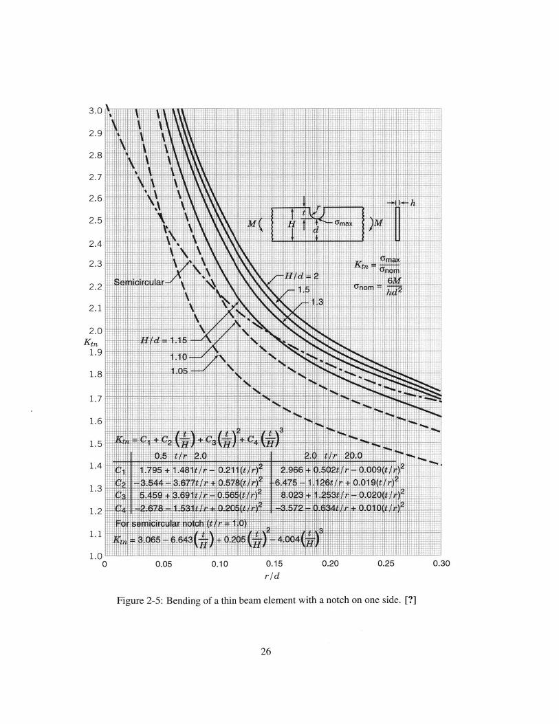
contribute to more precise and consistent folding. Using the information from Figures 2-4
and 2-5 [?] along with an estimate of the thin-film geometry and material properties, we
may calculate and plot the resulting non-dimensionalized stresses shown in Figure 2-6.
In Figure 2-6 where A is approximately equal to 0.83 the nominal stress of the sheetH4
is approximately equal to the yield stress of the material. As A is reduced the nominal
stress continues to increase well above the yield stress, aiding in springback reduction
along the scoreline. Thus, for the given set of parameters, it would be prudent to operate
with a scoring depth deeper than 0. 17H, to induce localized yielding to aid in springback
22

50
45
40
35
30
25
20
15
10
5
0
0 0.1 0.2 0.3 0.4 0.5 0.6 0.7 0.8 0.9
d1
I
Figure 2-3: Euler beam bending model dimensionless ligament thickness vs. curvature
ratio.
23
rq2

reduction.
24

4.0 M M m % . M W C +
38 i4tt
3.6 1
3.4 -
n"'t1r e4
14 t u * -
Kt,
3.0
2.8 t
Kta a a ne .2.6 Ij M1011
A: t 2.4
2.2 ..
2.0 nut .: 1.1
1.8
1 6 7 H
1.4 -4i J 4 u
1.4~ 7
tt NiH
1.20
1.0 1.2 1.4 1.6 1.8 2.0 2.2 2.4 2.6 2.8 3.0 3.2 3.4 3.6 3.8 4.0
Figure 2-4: Effect of notch angle on stress concentration factors for a thin beam element in
bending with a v-shaped notch on one side. [?]
25
411 I.
.1.
F ~' I2.9
2.8
2.7
2.6
2.5
2.4
2.3
2.2
2.1
2.0Ktn
1.9
1.8
1.7
1.6
1.5
1.4
1.3
1.2
1.1
1.0
1 t 74 -t tt 1 177 tT~ tA'Ft"
2T
h1
Z1 717 w 2tit (
t A/ 2
111V S4 4 0 6 t
E~~~ ~ T 1t-ah i &D 0
~5iQ fit CL&±iiIttt fl I ~ r~ rhMi~kf4hL~lL21 2rrr
0.05 0.10
[ii4il$iHIhHYHiBftiEiI4tfhIBU[ltlViiIVIiH' II? t11 L
0.15
rid
:F77fi7III
0.20
2t2~*1
-.4: -
0.25
S
.4:
F. I
0.30
Figure 2-5: Bending of a thin beam element with a notch on one side. [?]
26
3.0
t-- rtTt 7= 7
tit4 lijj lt4 fl Ot
a IV. 1~~~ -194~ el* K ' . -rl K Ti 1
F42~~1~L 4 42
0
'T7
4
&7 EFT
i-If 11 I-,I jtt14
Li
t 4
t IL .1 i--1LL I---
i--- LT i

10
9 *7nom
8 (74
7 i
6 .. .
4
1
0 ... ---------- -- --
0 0.1 0.2 0.3 0.4 0.5 0.6 0.7 0.8 0.9 1
Figure 2-6: Dimensionless ligament thickness vs. dimensionless stress, based on stress
concentration analysis for E = 150MPa, Ty = 12MPa, r = 11pm, H = 132pm.
27

Chapter 3
Design of the Experimental Apparatus
In this chapter, we discuss the design and development the rollforming machine for the
proposed folding operation. The central idea for the design is to take in a flat, thin-film
and gradually achieve sequential folds through rollforming stands. To begin the section we
shall discuss the mechanical properties of the thin-films that were used in this work and
guided the sizing of the experimental apparatus.
3.1 Mechanical Characterization of the Thin-Films
As mentioned previously, placebo films have been used in this study. The mechanical
characteristics of these films were employed for the development of the forming process
using the design guidelines and rationale discussed in Chapter 2.
Figure 3-1 shows the universal mechanical tester on which experiments were carried
out for this study. Figure 3-2 shows the stress-strain curve of the placebo film. A strain
rate of 1 mm/mm-min was used during experimentation. From the figure, it is clear that
the placebo film exhibits fairly distinct elastic and plastic regimes and a large elongation at
break.
The initial design of the experimental apparatus was performed based on the properties
of the given placebo film and after some preliminary testing, fine-tuning of the apparatus
was achieved.
28

Figure 3-1: Zwick universal tester used for thin-film material property characterization.
w
10
8
6
4
2
00.05 01 015 0.2 0.25
Engineenng Strain
Figure 3-2: Characteristic stress-strain curve for placebo thin-film.
29

3.2 Functional Requirements
The goal of developing the experimental apparatus was to carry out studies on the folding
operation. The main functional requirements for this setup are:
1. Accept and align the thin-film at the entrance roll stand.
2. Gradually fold the thin-film without tearing or excessive wrinkling.
3. Gather the folded thin-film together for subsequent processing.
3.3 Machine Components
The main components of the experimental apparatus necessary to achieve the aforemen-
tioned functional requirements are:
1. Entrance Rollers: The purpose of the entrance rollers is to take in and guide the
thin-film into the folding section, as shown in Figure 3-3.
XFilmi
Entrance Rollers
Figure 3-3: Entrance rollers to the rollforming station.
2. Folding Discs: The folding discs are key to the folding process. As the film passes
through the folding rollers, the sheet is deformed and folds are created. Any scoring
features are also machined onto these same discs. Figures 3-4 and 3-5 show the
folding disc sub-assembly required to make one and three folds respectively. The
folding discs are mounted on a shaft and kept in position using precision spacers. An
illustration of a folding unit is shown in Figure 3-6.
30

Folding Discs
Figure 3-4: Folding rollers for 1-fold stand.
Figure 3-5: Folding rollers for 3-fold stand.
31
Spacers
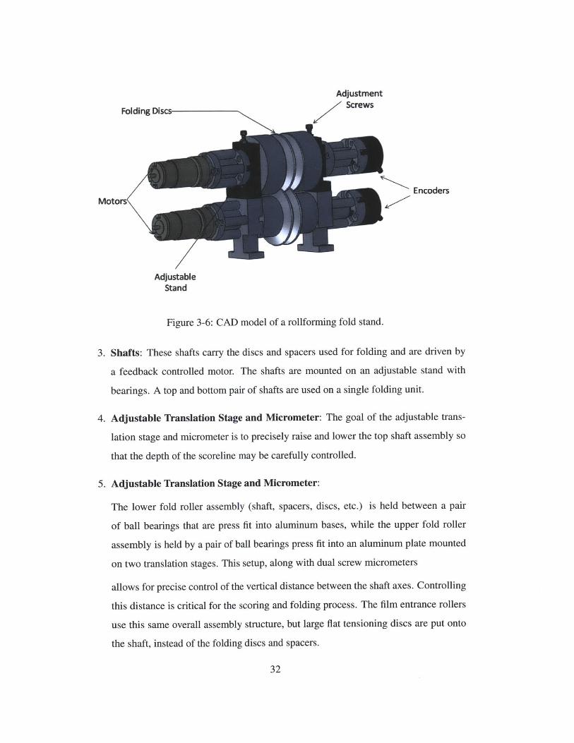
Adjustment
Folding Dis Screws
EncodersMotor
AdjustableStand
Figure 3-6: CAD model of a rollforming fold stand.
3. Shafts: These shafts carry the discs and spacers used for folding and are driven by
a feedback controlled motor. The shafts are mounted on an adjustable stand with
bearings. A top and bottom pair of shafts are used on a single folding unit.
4. Adjustable Translation Stage and Micrometer: The goal of the adjustable trans-
lation stage and micrometer is to precisely raise and lower the top shaft assembly so
that the depth of the scoreline may be carefully controlled.
5. Adjustable Translation Stage and Micrometer:
The lower fold roller assembly (shaft, spacers, discs, etc.) is held between a pair
of ball bearings that are press fit into aluminum bases, while the upper fold roller
assembly is held by a pair of ball bearings press fit into an aluminum plate mounted
on two translation stages. This setup, along with dual screw micrometers
allows for precise control of the vertical distance between the shaft axes. Controlling
this distance is critical for the scoring and folding process. The film entrance rollers
use this same overall assembly structure, but large flat tensioning discs are put onto
the shaft, instead of the folding discs and spacers.
32

6. Motors and Drive: For each folding stand, a DC motor (M32PO721YBGT3) with
a gear reduction was selected. A schematic illustration of the DC-motor, its drive
and controller are shown in Figure 3-7. For the final traction rollers, a servomotor
(AKM63K-VBCNR-00) and drive (AKD-P012-NAAN-000) were selected. More
details on the electronics employed in this study can be found in [?].
7. Traction Rollers: As the folded thin-film exits out of the folding section, vertical
traction rollers are needed to provide the necessary force to pull the film through for
subsequent processing. Figure 3-8 shows the traction rollers and stand assembly.
8. Encoders: The encoders are present to provide closed-loop feedback control for the
folding motors.
The thin-film is guided into the folding section through the entrance rollers. It is grad-
ually folded as it is driven by the individually controlled fold stands and pulled through by
the final traction stand.
The folding stands were designed to have a high degree of modular flexibility in or-
der to enable precise control and quick changeover between the folding disc geometries.
By altering and substituting these discs, we could more easily control the folding process
parameters and fine tune the operation.
The pharmaceutical thin-film enters through a flat tension roller, then is gradually folded
as it is driven by the individually controlled fold stands and pulled through by the final
vertical traction stand. The folding station was designed to have a high degree of modular
flexibility in order to enable precise control and quick changeover of the folding process
parameters.
Each fold stand is comprised of a top and bottom shaft with folding discs and spacers.
The shafts' motion is coupled through spur gears, which are driven by a shared DC servo-
motor, allowing independent control of the thin-film feed velocity between one fold stand
to the next.
Finally, material properties of key machine components are listed in Table 3.1
33

RS232 to RS485Converter shown
3
Com Or DB9 or USB cable
Comm Port suppled
Figure 3-7: Folding stand electric motor and drive schematic.
34
Li
80 F

VTraction Rollers
Figure 3-8: CAD model of the rollforming final traction stand.
35

Table 3.1: Material list for machine components.
Folding Stands
Spacers
Folding Discs
Entry Rollers
Shafts
Traction Stand
606 1-T6 Al
6061-T6 Al
303 machineable stainless steel
303 machineable stainless steel
Hardened 1566 steel
303 machineable stainless steel
36

Chapter 4
Experimental Results
In the previous chapter, we discussed the design and implementation of the experimental
apparatus used in the testing and development of a continuous rollforming process in order
to fold placebo thin-films. In this chapter, we will report and discuss the findings of the
performed experiments.
Broadly speaking, we have considered folding of films (i) without scoring and (ii) with
scoring. Here, scoring implies that local plastic deformation occurs along desired lines in
an effort to facilitate folding.
The degree of scoring is largely controlled by the profile and position of the folding disc.
Figures 4-2 and 4-3 show the disc profiles that would be employed for folding without and
with scoring, respectively. In the case in which folding is attempted without scoring, the
key parameter for the disc is contact radius R. In the case of folding with scoring, the
defining scoring geometry, hs and 0 , has a profound impact on the process.
The effect of scoring on the thin-film can be understood from Figure 4-4. In this figure:
1. H is the thickness of the film.
2. hs is depth of the score.
3. w is the width of the score.
4. 0 is the defining angle for the score.
37

Figure 4-1: Rollforming folding stand unit.
R
Figure 4-2: Folding disc profile without scoring feature.
38

R
Figure 4-3: Folding disc profile with scoring feature. Not to scale.
W
H
d
Figure 4-4: Film geometry along scoreline.
39

Excessive Consistent . InsufficientScoring Folding ' Scoring
H
Figure 4-5: Folding regime identified for scoring.
Based on the preliminary calculations and experiments, a useful scoring geometry was
identified. More importantly, we have identified that folding operations can largely be di-
vided into three operating regions when considering the use of scoring. These operating
regions are represented in Figure 4-5 and are primarily governed by the ratio A12 and their
associated errors. When jt = 0, it is observed that excessive scoring has occured, resulting
in a cutting or tearing failure along the desired fold line. Tearing makes material handling
more difficult and is undesirable for the current folding apparatus. If 2t = 1 it may be
concluded that no scoring has occured and subsequently no clear fold line is developed.
Without having a distinct line which prescribed folding may follow, the thin-film is more
likely to have alignment issues, drifting and folding in an undesirable manner. These pro-
cess errors stem from system inaccuracy and the input material's thickness and material
property variation. In a particular region enclosed by the lower limit, L, and upper limit,
U, an acceptable and useful level of scoring was achieved that resulted in more consistent
folding. Figure 4-5 shows the discussed folding regimes. The operating limits are shaded
to denote the process uncertainty near those regions. L and U may be estimated as
40

L Ed + EH (4.1)H
and
U = - Ed + EH (4.2)H
where Ed is the scoring depth error, largely due to the radial runout of the shaft-disc
assembly, and EH is the thin-film thickness error. Thus, the scoring process should be set
such that
dL < - < U (4.3)
H
Due to the complexity of the process, the stated value of U is an initial upperbound es-
timate that should be determined further through experiment. Because of this, experiments
were ran nearer to the lower operating limit.
For the current process ed 38pm and EH 15pm. Given that H = 132pm, the rec-
ommended operating window was somewhat small, but with proper control of the scoring
depth, successful folding was achieved.
4.1 Folding Experiments
As discussed in the previous section, folding may be executed with or without using a scor-
ing operation. In this study, we have attempted both strategies, and our resultant findings
broaden our understanding of the issues associated with the folding operation.
Folding without scoring:
In this approach, we used the discussed experimental apparatus, assembled with folding
discs without scoring features in an effort to achieve simple folds. The following issues
were encountered during tests ran with the non-scoring strategy:
1. Difficulty feeding the thin-film into the entrance folding stand due to misalignment
and slipping.
41

Figure 4-6: Experimental apparatus assembled with non-scoring discs, view 1
Figure 4-7: Experimental apparatus assembled with non-scoring discs, view 2
42

Figure 4-8: Thin-film undergoing folding process without scoring.
2. Difficulty maintaining the alignment of the thin-film while passing through the fold-
ing stands due to drifting.
We were able to achieve folding without scoring and results are shown in Figures 4-6
and 4-7, however the process was difficult to control due to the aforementioned issues.
Folding with scoring:
In this approach, we first scored the thin-film, then sought to create folds. Figures 4-
11 and 4-10 show the scored and folded thin-film entering the traction rollers. The follow-
ing observations were made during these operations:
1. Scoring of the thin-film developed a distinct line for folding and facilitated alignment
control.
2. Due to the thin-film thickness variation, it was sometimes difficult to precisely con-
trol the depth of the score.
The scoring process was tested at varying depths and it was found that at lower depths,
incomplete scoring would lead to inconsistent folding, often leading the thin-film to drift
and bind the system. In contrast, sufficient scoring led to more a more consistent folding
process. The resulting folded thin-films are shown in Figures 4-12 and 4-13. Microscopic
images of thin-films with several scoring depths are shown shown in Figures 4-14 and 4-15.
43

<. . 0 0 0 0
Figure 4-9: Experimental apparatus assembled with scoring discs, view 1
44

Figure 4-10: Experimental apparatus assembled with scoring discs, view 2
Figure 4-11: Scored thin-film exiting final traction rollers.
45

Figure 4-12: Folding with partial scoring and drifting defects.
46

Figure 4-13: Scored thin-film output specimen.
Figure 4-14: Microscopic image of scoreline with w = 69.8pm, ds = 34.9pm.
47

Figure 4-15: Microscopic image of scoreline with w = 33.3pm, ds = 16.7pm.
The experimental apparatus developed in this study was used to investigate thin-film
folding with and without the use of a scoring operation. Folding could be achieved using
either strategy with appropriate process parameters, although scoring appears to have made
the process more robust to the current system and input imperfections. From these prelimi-
nary tests, several useful observations were noted, but more analysis and testing is required
to more fully determine the operating range for either strategy in order to produce a higher
number of folds with greater consistency.
48

Chapter 5
Conclusions and Future Work
Rollforming processes have been widely employed in the past for a variety of applications.
In this work, we sought to leverage this past knowledge base and undertook the task of
developing a rollforming folding strategy for the continuous manufacturing of pharmaceu-
tical thin-films. The focus of this thesis was to investigate the steps of folding in detail for
the overall strategy of liquid solvent casting, folding, bonding and shaping of thin-films in
a continous tableting operation.
First, existing rollforming processes were analyzed and theoretical investigations were
carried out on the bending, or folding, of a notched, or scored, specimen. This was done in
light of the fact that notches facilitate the bending of an element and increase the endured
stress. The overall folding operation depended upon the thin-film material properties, load-
ing conditions and the dimensions of the score. These elements provided the guidelines for
later development of a scoring strategy for folding.
An experimental apparatus was designed and assembled to test and further develop the
process for folding thin-films. The apparatus consisted of a film-feeding module, followed
by a set of rollforming stations to carry out folding, and traction rollers to provide the nec-
essary forward drive for the thin-films. Mechanical characterization of the thin-films was
performed and the properties were found useful in the design of the setup. The flexibility
and modularity of the setup allowed for the convenient interchange of the parts.
Two folding strategies were proposed: (a) folding without scoring and (b) folding with
scoring. In folding without scoring, the goal was to operate within the elastic regime of the
49

thin-film without causing significant plastic deformation. Whereas in folding with scoring,
local plastic deformation was introduced to form creases to initiate and guide the process.
Both strategies were found to be successful with certain advantages and disadvantages to
each.
In folding without scoring, input misaligment and system inaccuracy, namely assem-
bly run-out, were major issues that negatively affected the process. The key challenge in
scoring is to achieve an appropriate penetration depth, without cutting through the material.
Overall, the folding operation can be categorized into three regimes: (i) negligible or no
scoring (ii) sufficient scoring, and (iii) excessive scoring or tearing. The middle regime of
sufficient scoring is desirable so that consistent folding without failure may be achieved.
In future work, both strategies could be explored for a larger number of folds. Regard-
ing the experimental apparatus, a more accurate assembly and controls process is recom-
mended, along with improved process control in solvent casting. The experimental thin-
films had a thickness of approximately 132 i 15pm. This variation in thickness, combined
with the machine assembly error during operation, resulted in a varying score depth and
thus hindered the goal of uniform scoring and folding. This non-uniformity affected the
local stiffness near the fold, leading to inconsistent and often negative results. A more uni-
form thin-film thickness would likely have a profound impact in enabling a more consistent
folding process.
In the future, more thorough estimates and modeling techniques could be employed to
devise a more appropriate and detailed model for thin-film rollforming. The findings made
in this study should guide the development of future processes and machines for use in
continuous thin-film tableting.
50

Bibliography
[Ded(2010)] The canary in the coal mine -migraine. http: //miter. mit. edu /node/152,
2010.
[mot(2011)] http://www.micro-drives.com, 2011.
[Bayoumi and Lee(2004)] Laila S. Bayoumi and Youngseog Lee. Effect of interstand ten-
sion on roll load, torque and workpiece deformation in the rod rolling process. Journal
of Materials Processing Technology, 145:7-13, 2004.
[Bennett and Cole(2003)] B. Bennett and G. Cole. Pharmaceutical production: An engi-
neering guide. An Engineering Guide, Institution of Chemical Engineers, UK, 2003.
[Bhattacharya(1984)] D. Bhattacharya. The prediction of deformation length in cold roll-
forming. Journal of Mechanical Working Technology, 9:273-291, 1984.
[Carrel(1970)] R. Carrel. Process for continuous manufacture of rigid corrugated card-
board with crossed corrugations, 1970. US Patent 3513054.
[Deshpande et al.(1997)Deshpande, Shah, Rhodes, and Malick] A. A. Deshpande, N. H.
Shah, C. T. Rhodes, and W. Malick. Evaluation of films used in development of a
novel controlled-release system for gastric retention. International Journal of Phar-
maceutics, 159(2):255-258, 1997.
[Ding and Duncan(2009)] Ding and Duncan. A wide-panel forming process to replace
conventional rollforming. International Journal of Mechanical Sciences, 51:276-
283, 2009.
51

[Duggal(1995)] Nitin Duggal. Process simulation of roll forming and roll pass design.
Master's thesis, Ohio State University, 1995.
[Gad(2008)] S. C. Gad. Pharmaceutical Manufacturing Handbook: Production and Pro-
cesses. John Wiley & Sons, Hoboken, NJ, 2008.
[Halmos(2006)] George T. Halmos. Roll Forming Handbook. Taylor & Francis, 2006.
[Hong(2001)] Sukmoo Hong. A parametric study on forming length in roll forming. Jour-
nal of Materials Processing Technology, 113:774-778, 2001.
[Kim et al.(2003)Kim, Lee, Yoo, Choo, and Kim] D. H. Kim, Y. Lee, S. J. Yoo, W. Y.
Choo, and B. M. Kim. Prediction of the wear profile of a roll groove in rod rolling
using an incremental form of wear model. Proc. Instn Mech. Engrs Part B: J. Engi-
neering Manufacture, 217:111-126, 2003.
[Kim(2010)] Won Kim. Layer bonding of solvent cast thin films for pharmaceutical solid
dosage forms. Master's thesis, MIT, 2010.
[Lee(2002a)] Youngseog Lee. New approach for prediction of roll force in rod rolling.
Ironmaking and Steelmaking, 29(6):459-469, 2002a.
[Lee(2002b)] Youngseog Lee. Prediction of the surface profile and area of the exit cross
section of workpiece in round-oval-round pass sequence. ISIJ International, 42(7):
726-735, 2002b.
[Lindgren(2007)] M. Lindgren. Cold roll forming of a u-channel made of high strength
steel. Journal of Materials Processing Technology, 186:77-81, 2007.
[Mahato(2008)] R. I. Mahato. Pharmaceutical Dosage Forms and Drug Delivery. CRC
Press, Boca, Raton, FL, 2008.
[Marin and Keyt(1975)] M. James Marin and Ferris Gene Keyt. Sheet folding device,
1975.
[Marin and Keyt(1994)] M. James Marin and Ferris Gene Keyt. Method for forming
pleates in a sheet-like material, 1994.
52

[Ona(1990)] Hiroshi Ona. Research into the cold roll-forming of vibration-damping steel
sheet. Journal of Materials Processing Technology, 23:7-20, 1990.
[Ona and Jimma(1983)] Hiroshi Ona and Takashi Jimma. Experiments into the cold roll-
forming of straight asymmetrical channels. Journal of Mechanical Working Technol-
ogy, 8:273-291, 1983.
[Panton(1994)] S.M. Panton. Fundamental deformation types and sectional properties in
roll forming. Int. J. Mech. Sci., 36(8):725-735, 1994.
[Pilkey and Pilkey(2008)] W. Pilkey and D. Pilkey. Peterson's Stress Concentration Fac-
tors 3rd Edition. John Wiley and Sons, Hoboken, New Jersey, USA., 2008.
[Sinha et al.(2010)Sinha, Curtis, Hancock, and Wassgren] Tuhin Sinha, Jennifer S. Curtis,
Bruno C. Hancock, and Carl Wassgren. A study on the sensitivity of druckerprager
cap model parameters during the decompression phase of powder compaction simu-
lations. Powder Technology, 198(3):315 - 324, 2010.
[Watari and Ona(2001)] Hisaki Watari and Hiroshi Ona. Cold-roll forming of smaller-
diamter pipes with pre-notches. Journal of Materials Processing Technology, 119:
122-126, 2001.
53