the design of tension test sensor and its finite … · the design of tension test sensor and its...
TRANSCRIPT

Sensors & Transducers, Vol. 155, Issue 8, August 2013, pp. 47-53
47
SSSeeennnsssooorrrsss &&& TTTrrraaannnsssddduuuccceeerrrsss
© 2013 by IFSAhttp://www.sensorsportal.com
The Design of Tension Test Sensor and its Finite Element Analysis and Test Research
1 HONG-YU LIU, 1 ZE-NING XU, 2 JUN-JIE XI
1 School of Mechanical Engineering and Automation, University of Science and Technology Liaoning, Anshan, Liaoning Province, China, 114051, China
2 School of Mechatronics Engineering, Zhengzhou Institute of Aeronautical Industry Management, Zhengzhou, Henan Province, China, 450015, China
1 Tel.: 15241277551, fax: 0412-5929777 1 E-mail: [email protected]
Received: 1 June 2013 /Accepted: 12 August 2013 /Published: 20 August 2013 Abstract: The tension test method of strip steel on stretching winding straightener tension roll group was elaborated. The material and paster form of resistance strain foil in tension test sensor were designed. The measure circuit of tension test sensor was designed. The material and structural form of elastic body of tension test sensor were designed. Strength computation was made on elastic body of tension test sensor. Three-dimensional entity model of elastic body of tension test sensor was built by SolidWorks software. Finite element analysis was made on relative model by ANSYS software. Relative stress figure and displacement figure of elastic body of tension test sensor were obtained. Tension test sensor was manufactured based on design. Static state compression rigidity test of elastic body of tension test sensor was made. Relative test system constitution, test method and test process were elaborated. Relative test data were disposed. This research provides reliable base for the design of tension test sensor. Copyright © 2013 IFSA. Keywords: Tension test sensor, Strength computation, Finite element analysis, Test research. 1. Introduction
Many industries such as spaceflight, national defence, domestic appliance, printing, and so on were developed rapidly at present. The need quantity of cold rolling strip steel increases rapidly. The quality requirement of cold rolling strip steel is stricter. During the continuous production process of cold rolling strip steel, stretching winding straightener was adopted used widely to realize relative techniques purpose. So, more and more attentions were paid to stretching winding straightener in various cold rolling strip steel production line [1, 2].
The important way of eliminate strip steel defect and improve strip steel plate shape quality is adopting
stretching winding straightening technology. The accurate control of stretching winding straightening process and the improvement of strip steel quality can be realized by effective strip steel tension test. Tension test sensor is the key of strip steel tension test. Tension test sensor is the window of perceiving and obtaining test information in tension test system. The information obtained by tension test sensor decides the capability of tension test system directly. Automation control system research of strip tension leveller was made by Zhiguo Jia and Zhiyong Chen in cold rolling mill of Benxi Iron and Steel Company in 2002 [3]. Fault analyzing of elongation tension control system of tension leveller stretcher was made by Qin Wen and Zhiyong Chen in Benxi Iron and
Article number 1286

Sensors & Transducers, Vol. 155, Issue 8, August 2013, pp. 47-53
48
Steel Company in 2003 [4]. The application of microcomputer control electron universal testing machine in materials mechanics teaching experiment was made by Wenlong Zheng in National University of Defense Technology in 2008 [5]. Study on the static rigidity of damper rubber product tested with computer controlled amsler tupe tester was made by Junqing Ren and Guiyi Wang in Zhongnan Rubber Group Company in 2008 [6]. The application of weigh sensor on tension test and control of twenty rollers rolling mill was made by Wenhong Yang, Baowen Li and Dongqing Wang in Baoji Titanium Group Limited Company in 2010 [7]. Automatic control system of tension stretching straightener in scouring and rolling union assemblies was made by Zhaogang Lu, Junxiang Dong and Yungang Huang in Liuzhou cold rolling strip mill in 2010 [8]. Study and application of tension leveller of PL-TCM at Meigang was made by Yingjie Zhang, Qingling Yang and Zhigang Li in cold rolling plant of Meishan Iron and Steel Company in 2010 [9]. Intelligent detection system tension was made by Xin Zhang, Kun Yang and Cheng Zhang in Tianjin Polytechnic University in 2010 [10]. Design and analysis on intelligent tension detection system based on bluetooth was made by Hongjun Liu and Shengkun Sun in Tianjin Military Affairs Deputy Bureau of Navy Equipment Ministry in 2012 [11].
In a word, now, some researches have been made on the test and control of strip steel tension of stretching winding straightener. While, there are also some deficiencies. The sensor used in certain cold rolling mill stretching winding straightener tension test is imported. Its price is very high. Its work condition is very bad. There is not blueprint in mill. This causes great influence on the test precision and working life of sensor. This also causes many inconveniences in sensor servicing. So, the sensor was designed and manufactured in this paper. Relative finite element analysis and test research were made to insure the normal operation of straightener.
2. Tension Test Method Tension is an important parameter in stretching
winding straightener. It relates to the regular work state of stretching winding straightener. Tension test method is to transform the inlet tension and outlet tension of every tension roll into horizontal resultant. The resultant was transmitted to lever connected with sensor by support arm. The resultant can be solved by lever principle. Tension test picture is shown as Fig. 1.
In Fig. 1, A point is fixed hinge point between lever and framework. B point is the horizontal force pass point acted on lever by bearing block. C point is the force pass point acted on sensor by lever.
BF is
the horizontal resultant transformed from the inlet tension and outlet tension of every tension roll.
cF is
the force tested by sensor. The distance between A point and C point is two times as long as the distance between A point and B point. Strip steel tension can be solved by lever principle, which is shown as Formula (1).
C B
ABF F
AC , (1)
1- Bearing Block, 2- Framework, 3- Lever, 4- Baffle, 5- Sensor, 6- Base
Fig. 1. Tension Test Picture. 3. Tension Test Sensor Design
3.1. Tension Test Sensor Constitution
Resistance strain sensor designed independently
was used as tension test sensor in this paper. The three parts of this sensor are resistance strain foil, test circuit and elastic body. Strain foil material is nicochrome. Strain foil standard resistance value is 120 . Test circuits are all full bridge equiarm constant current bridge, which is shown as Fig. 2. Elastic body structure is solid pin roll form, which is shown as Fig. 3.
Fig. 2. Test circuit picture.
Fig. 3. Elastic body structure picture.

Sensors & Transducers, Vol. 155, Issue 8, August 2013, pp. 47-53
49
After loading on elastic body, shear stress caused by shear force need to be tested. So, four strain foils were stuck on both sides of I beam sterna. They are placed on 45° angle relative to central axis. The strain foils paster place is shown as Fig. 4. The four strain foils constitute full bridge. The symmetric output engendered on bridge diagonal is proportional to load with resistance value increase of strain foil R1 and R3 and resistance value decrease of strain foil R2 and R4. Strip steel tension can be tested by this principle.
Fig. 4. The strain foils paster place picture. 3.2. Strength Computation of Elastic Body
of Tension Test Sensor The section passed through elastic body blind
hole centre can be regarded as part I beam section. The section contains upper flange, bottom flange and middle plate. The section and relative shear stress and bend stress are shown as Fig. 5.
Fig. 5. Beam section and relative shear stress and bend stress.
The maximum bend stress max and shear stress
max of sensor elastic body can be solved by formula
(2) and (3) respectively.
max 3 3 3
6QeH
BH Bh bh
, (2)
2 2 2
max 3 3 3
3
2
Q BH Bh bh
b BH Bh bh
, (3)
The yield stress of elastic body s is 930 MPa.
The allowable bend stress [ ] of elastic body is
279 MPa. The allowable shear stress [ ] of elastic
body is 186 MPa. The distance from section poid to section fringe e is 40 mm. The load on the fourth tension roll is 85.843 kN. This load was loaded on elastic body of sensor. I beam section height h is 30 mm. I beam section width B is 65 mm. The plate width b is 22 mm. After substituting these parameters into formula (2) and (3) respectively,
max and
max were computered respectively with relevant
value 60.93 MPa and 74.21 MPa. max and
max are
all less than relevant allowable stress. So, the tension test sensor designed in this paper can satisfy spot strength requirement.
4. Finite Element Analysis of Elastic Body of Tension Test Sensor
4.1. The Construction of Elastic Body Finite Element Model of Sensor
Three-dimensional entity model of elastic body of
sensor was constructed by SolidWorks software in this paper. It was saved as parasolid document form. Then, the relevant model was led into and analyzed by ANSYS software. The relevant model was shown as Fig. 6.
Fig. 6. Three-dimensional entity model of elastic body of sensor.
4.2. Property Definition, Grid Division,
Constraintion and Load of Elastic Body of Sensor
The material property of elastic body E is
2.06×10⁵ N/mm2. Poisson ratio is 0.26. Density
is 7.81 kg/mm3. SOLID187 element and free grid
division method were adopted on grid division of elastic body. The displacements on Y axis and Z axis of elastic body circle face supported by base were set as zero constraintion. The displacements on X axis of two elastic body groove sides were set as zero constraintion. The displacements on Y axis of elastic body underside were set as zero constraintion. The connected position between elastic body and support arm was loaded as equispaced load. The tension on the fourth roll outlet is 85.843 kN. It was set as the load during analysis process. The analysis of this
Sensors & Transducers, Vol. 155, Issue 8, August 2013, pp. 47-53
50
research is finite element statics analysis. So, equispaced load can be transformed to concentrate load according to equivalent principle. The relevant concentrate load was loaded on five nodes. The relevant grid division, constraintion and load of elastic body are shown as Fig. 7.
Fig. 7. The relevant grid division, constraintion and load of elastic body.
4.3. The Finite Element Analysis Result of Elastic Body of Sensor
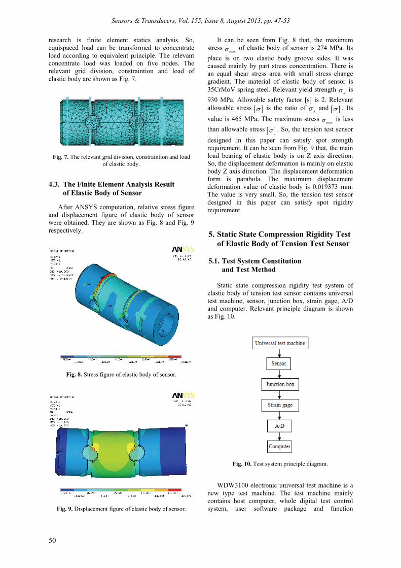
After ANSYS computation, relative stress figure and displacement figure of elastic body of sensor were obtained. They are shown as Fig. 8 and Fig. 9 respectively.
Fig. 8. Stress figure of elastic body of sensor.
Fig. 9. Displacement figure of elastic body of sensor.
It can be seen from Fig. 8 that, the maximum stress
max of elastic body of sensor is 274 MPa. Its
place is on two elastic body groove sides. It was caused mainly by part stress concentration. There is an equal shear stress area with small stress change gradient. The material of elastic body of sensor is 35CrMoV spring steel. Relevant yield strength
s is
930 MPa. Allowable safety factor [s] is 2. Relevant allowable stress is the ratio of
s and . Its
value is 465 MPa. The maximum stress max is less
than allowable stress . So, the tension test sensor
designed in this paper can satisfy spot strength requirement. It can be seen from Fig. 9 that, the main load bearing of elastic body is on Z axis direction. So, the displacement deformation is mainly on elastic body Z axis direction. The displacement deformation form is parabola. The maximum displacement deformation value of elastic body is 0.019373 mm. The value is very small. So, the tension test sensor designed in this paper can satisfy spot rigidity requirement. 5. Static State Compression Rigidity Test
of Elastic Body of Tension Test Sensor
5.1. Test System Constitution and Test Method
Static state compression rigidity test system of
elastic body of tension test sensor contains universal test machine, sensor, junction box, strain gage, A/D and computer. Relevant principle diagram is shown as Fig. 10.
Fig. 10. Test system principle diagram.
WDW3100 electronic universal test machine is a new type test machine. The test machine mainly contains host computer, whole digital test control system, user software package and function

Sensors & Transducers, Vol. 155, Issue 8, August 2013, pp. 47-53
51
attachment, and so on. It is shown as Fig. 11. The host computer has the characteristics such as function stability, reliability and high test control precision. The tension test sensor designed and manufactured independently is shown as Fig. 12.
Fig. 11. WDW3100 electronic universal test machine.
Fig. 12. The tension test sensor designed and manufactured independently.
The strain foils paster place of elastic body of sensor is shown as Fig. 13. In Fig. 13, the strains of R1 and R3 are stretching strains. The strains of R2 and R4 are compress strains. Bridge arm working condition coefficient C is 4. The strain foil resistance values are all 120 .The strain foil sensitive coefficient
sK is 2.20. The calibrated strain of strain
instrument s is 1000 . The join pattern between
strain foil and junction box is shown as Fig. 14.
Fig. 13. The strain foils paster picture
Fig. 14. The join pattern between strain foil and junction box.
BZ2201 dynamic strain gauge is an automatic balance strain instrument. Relevant alternating power supply voltage is 220 voltages. Relevant constant current power supply voltage is 12 voltages. It is shown as Fig. 15. The relevant test method contains following steps. Firstly, strain foils were stuck on blind holes underside of elastic body of sensor. Secondly, the strain of blind holes underside can be transformed as strain foil resistance change. Then, the strain foil resistance change can be transformed as voltage change. Finally, the voltage change can be shown by strain gauge.
Fig. 15. BZ2201 dynamic strain gauge.
5.2. Test Process and Data Processing
Static state compression rigidity test of elastic body of tension test sensor was made by universal test machine. Relevant load signals and displacement signals come from load sensor and displacement sensor placed on universal test machine were sent into controller. After amplifying and A/D transforming, relevant signals were sent into computer. The disposed signals were shown on screen synchronously. So, load-displacement curve was formed. It is shown in Fig. 16.

Sensors & Transducers, Vol. 155, Issue 8, August 2013, pp. 47-53
52
Fig. 16. Load-displacement curve.
It can be seen from Fig. 16 that, the initial short section of load-displacement curve is a curve. Hinder long section of load-displacement curve is an approximative slant. Relevant load scope is 0 kN to 90 kN. So, under this load, elastic body of tension test sensor is on elastic stage. The load on the fourth tension roll is 85.843 kN. This load is in the load scope of universal test machine. So, under the normal work of tension test sensor, relevant elastic body is also on elastic stage. Relevant deformation is also elastic deformation. So, the tension test sensor designed in this paper can satisfy spot rigidity and strength requirement. Three load tests were made on tension test sensor designed in this paper. Relevant output wave shapes of strain gauge are shown as (a), (b) and (c) of Fig. 17 respectively.
(a)
(b)
(c)
Fig. 17. Output wave shapes of strain gauge under three load tests.
It can be seen from Fig. 17 that, the relevant load scope is 0 kN to 90 kN. The output voltage is regarded as linear increase with the load increase approximatively. So, under the normal work of tension test sensor, relevant elastic body is also on elastic stage. Relevant deformation is also elastic deformation. So, the tension test sensor designed in this paper can satisfy spot rigidity and strength requirement. 6. Conclusions
The tension test sensor designed in this paper can satisfy spot strength requirement, which was validated by the strength computation of elastic body of tension test sensor. The tension test sensor designed in this paper can satisfy spot rigidity and strength requirement, which was validated by the finite element analysis of elastic body of tension test sensor by ANSYS software. The tension test sensor designed in this paper can satisfy spot rigidity and strength requirement, which was validated by the static state compression rigidity test of elastic body of tension test sensor. The strength computation, finite element analysis and static state compression rigidity test of elastic body of tension test sensor provide reliable base for the design of tension test sensor.
Acknowledgements This work was supported by the Science and Technology Tackle Key Problem Plan Major Project of Henan Province (No. 102102210389) and the Science and Technology Tackle Key Problem Plan Project of Henan Province (No. 082102230047). References [1]. J. M. Zhang, The problem happened in the actual use
for the tension leveller of PL-TCM and its analysis, Journal of Anhui Vocational College of Metallurgy and Technology, Vol. 5, Issue 2, 2005, pp. 25-28.
[2]. L. N. Zhou, Tensile bending leveller and its problems in application, China Metallurgy, Vol. 15, Issue 5, 2005, pp. 40-42.
[3]. Z. G. Jia, Z. Y. Chen, Automation control system research of strip tension leveller, Control Engineering of China, Vol. 9, Issue 3, 2002, pp. 29-31.
[4]. Q. Wen, Z. Y. Chen, Fault analyzing of elongation tension control system of tension leveller stretcher, Control Engineering of China, Vol. 10, Issue 1, 2003, pp. 62-64.
[5]. W. L. Zheng, The application of microcomputer control electron universal testing machine in materials mechanics teaching experiment, Test Technology and Testing Machine, Vol. 48, Issue 1, 2008, pp. 11-15.
[6]. J. Q. Ren, G. Y. Wang, Study on the static rigidity of damper rubber product tested with computer

Sensors & Transducers, Vol. 155, Issue 8, August 2013, pp. 47-53
53
controlled amsler tupe tester, Special Purpose Rubber Products, Vol. 29, Issue 3, 2008, pp. 57-60.
[7]. W. H. Yang, B. W. Li, D. Q. Wang, The application of weigh sensor on tension test and control of twenty rollers rolling mill, Plant Maintenance Engineering, Vol. 30, Issue 6, 2010, pp. 43-44.
[8]. Z. G. Lu, J. X. Dong, Y. G. Huang, Automatic control system of tension stretching straightener in scouring and rolling union assemblies, Liugang Science and Technology, Vol. 38, Issue 4, 2010, pp. 57-58.
[9]. Y. J. Zhang, Q. L. Yang, Z. G. Li, Study and application of tension leveller of PL-TCM at
meigang, Meishan Science and Technology, Vol. 31, Issue 5, 2010, pp. 4-7.
[10]. X. Zhang, K. Yang, C. Zhang, Intelligent detection system tension, in Proceedings of the 2010 International Conference on Information Technology and Scientific Management, Tianjin, China, 20-22 December 2010, pp. 771-774.
[11]. H. J. Liu, S. K. Sun, Design and analysis on intelligent tension detection system based on bluetooth, Radio Communications Technology, Vol. 29, Issue 1, 2011, pp. 3-5.
___________________
2013 Copyright ©, International Frequency Sensor Association (IFSA). All rights reserved. (http://www.sensorsportal.com)