the design, construction, operation, and maintenance of ...aquaticcommons.org/14617/1/nos nccos...
TRANSCRIPT

The Design, Construction, Operation, and Maintenance of the Replicated Modular Estuarine Mesocosm
NOAA Technical Memorandum NOS NCCOS 62

This report has been reviewed by the National Ocean Service of the National Oceanic and Atmospheric Administration (NOAA) and approved for publication. Mention of trade names or commercial products does not constitute endorsement or recommendation for their use by the United States government. Citation for this Report Pennington, PL., DeLorenzo, ME., Key, PB., Wirth, EF, Fulton, MH., Scott, GI. 2007. The Design, Construction, Operation, and Maintenance of the Replicated Modular Estuarine Mesocosm. NOAA Technical Memorandum NOS NCCOS 62. 77 pp.

The Design, Construction, Operation, and Maintenance of the Replicated Modular Estuarine Mesocosm. P. L. Pennington JHT Incorporated, Contractor to NOAA NOS NCCOS CCEHBR 13501 Ingenuity Drive, Suite 300 Orlando, FL 32826 M. E. DeLorenzo, P. B. Key, E. F. Wirth, M. H. Fulton, and G. I. Scott Center for Coastal Environmental Health and Biomolecular Research NOAA NOS NCCOS 219 Fort Johnson Road Charleston, South Carolina 29412-9110 NOAA Technical Memorandum NOS NCCOS 62 July 2007
United States Department of National Oceanic and National Ocean Service Commerce Atmospheric Administration Carlos M. Gutierrez Conrad C. Lautenbacher, Jr. John (Jack) H. Dunnigan Secretary Administrator Assistant Administrator

- i -

Dedication
To Dr. John R. Lauth whose experience, knowledge, and technical expertise laid the foundation for this work.

- iii -

Acknowledgements The authors would like to acknowledge several dedicated individuals who without their
tireless efforts, this work would not have been possible.
Jennifer Lawton Lyndall -- 1999-2002 Megan C. Singleton -- 2003
Jessica E. Hodge -- 2004 Cleve Robertson -- 2005
Heather E. Harper -- 2006-2007
We also acknowledge all those who have participated over the years during various stages of mesocosm construction, setup, collections, and experimentation.
Dr. Ruth Arabie LaTrisha Allen
Dr. Dan Bearden Dr. Adriana Bejarano
Jennifer Burkhart Dr. Karen Burnett Dr. Barbara Butler
Dr. G. Tom Chandler T.J. Christl Katy Chung Allan Clum
Cindy Cooksey Kathryn Crist
James Daugomah Dr. Alan Decho Holly Downing
J.D. Dubick Jennifer Emblidge
Dr. John Ferry Jessica Fleming
Meaghean Finnegan Anne Harrie
Ken Hayes Jennifer Hoguet
Sarah Hopsfensperger Kevin Huther
Sabrina Hymel Jeff Hyland
Kathleen Janech Christian Jones
Joseph Jutzi Brianne Kessler
Meagan Leatherbury Andrew Leight
Dr. Paige Leitman Dr. Mike Lewis
Dr. Alan Lewitus Shannon Lund Dr. Jan Moore
Dr. Patricia McClellan-Green
Dr. Henry McKeller Jeff Meyers
Christina Mikulski
Dr. Jay Pinckney Sherry Pittman Erin Sanders Dr. Yelena
Sapozhnikova Lorimar Serrano Brian Shaddrix Scott Sivertsen Rob Sumner
Jennifer Tobias Adrienne Tutko
Dr. Raphael Tymowski Stephanie Rexing
Dr. Phil Ross John Venturella
Dr. Spenser Walse Laura Webster Blaine West
Jeannette Wiener Jamie Willaims
Patrick Williams
Finally, we express our sincere thanks to the following people for their careful review of this publication.
Colden Battey Wayne McFee Blaine West

- iii -

- iv -
Executive Summary
Perhaps the most difficult job of the ecotoxicologist is extrapolating data calculated from laboratory experiments with high precision and accuracy into the real world of highly-dynamic aquatic environments. The establishment of baseline laboratory toxicity testing data for individual compounds and ecologically important individual species is the cornerstone of ecotoxicology. Extrapolations from laboratory and field studies serve as a precursor to ecosystem level studies needed for ecological risk assessment. The first stage in the field portion of risk assessment is the determination of actual environmental concentrations of the contaminant being studied and matching those concentrations with laboratory toxicity tests. Risk estimates can be produced via risk quotients that would determine the probability that adverse effects may occur.
In this first stage of risk assessment, environmental realism is often not achieved. This is due, in part, to the fact that single-species laboratory toxicity tests, while highly controlled, do not account for the complex interactions (chemical, physical, and biological) that take place in the natural environment. By controlling as many variables in the laboratory as possible, an experiment can be produced in such a fashion that real effects from a compound can be determined for a particular test organism. This type of approach obviously makes comparison with real world data most difficult. Conversely, field oriented studies fall short in the interpretation of ecological risk assessment because of low statistical power, lack of adequate replication, and the enormous amount of time and money needed to perform such studies. Unlike a controlled laboratory bioassay, many other stressors other than the chemical compound in question affect organisms in the environment. These stressors range from natural occurrences (such as changes in temperature, salinity, and community interactions) to other confounding anthropogenic inputs. Therefore, an improved aquatic toxicity test that will enhance environmental realism and increase the accuracy of future ecotoxicological risk assessments is needed.
One such improvement in the design of aquatic toxicity testing is the development of the aquatic mesocosm. As defined by Touart [1], aquatic mesocosms are intermediate-sized systems that test structural and functional parameters of aquatic ecosystems with the ability to be replicated and manipulated. Ecologists, such as population biologists, zoologists and botanists, have utilized the mesocosm concept for approximately 50 years in studying terrestrial and aquatic ecosystems. Toxicologists, ecotoxicologists, and environmental scientists have used mesocosms for about the past three decades.
Aquatic mesocosms allow for an integrated approach to ecotoxicology involving many parameters and interactions that were traditionally ignored in laboratory bioassays. These include, but are not limited to, physical characteristics (temperature and flow), chemical characteristics (contaminant mixtures, nutrient interactions, and fate/transport of contaminants), and biological characteristics (predator/prey relationships, food web interactions, and shifts in community structure and composition).
The majority of aquatic mesocosm studies have been based on freshwater ecosystems. Thus, very few ecotoxicological mesocosm studies have been performed on marine and estuarine systems [2]. In a paper by Lauth et al. [3], a modular estuarine mesocosm design was presented (Figures 1 and 2). The mesocosms presented in that study can be classified as "tidal" or "estuarine" and were originally pioneered by

- v -
researchers at Virginia Tech in Blacksburg, Virginia, USA and the Center for Coastal Environmental Health and Biomolecular Research (CCEHBR) in Charleston, South Carolina, USA.
The purpose of this document is to establish a consistent method for building and operating the mesocosm systems (as modified herein from the design by Lauth et al. [3]). Secondly, this document serves to transfer and promulgate the technology, knowledge and experience gained from the past 11 years of research to other researchers. This document may be of benefit to federal and state agencies, colleges and universities, private firms, and the general public.
The objectives of this document are four fold. First, the design modifications of the Replicated Modular Estuarine Mesocosm (RMEM) shall be described as they relate to the original design concept by Lauth et al. [3]. Secondly, a detailed, step-by-step process for the construction of one RMEM unit and its accompanying support equipment and facilities will be provided. Thirdly, a standard operating procedure (SOP) will be presented. Human health, environmental health and safety issues will be discussed in that section. The final section will include maintenance and troubleshooting guidelines.
This document will not discuss specific experimental designs or debate the use of mesocosms versus other toxicological approaches. Appendix 8 of this document contains a listing of publications which highlight a number of studies performed in these systems with varying experimental designs. Some of these also discuss the advantages and disadvantages of using mesocosms for toxicological research.

- vi -
Table of Contents Dedication ........................................................................................................................... ii Acknowledgements............................................................................................................ iv Executive Summary ........................................................................................................... iv Table of Contents............................................................................................................... vi List of Figures .................................................................................................................. viii Chapter 1: Design ............................................................................................................... 1
Marine and Estuarine Mesocosms................................................................................... 1 Chapter 2: Construction and Assembly .............................................................................. 5
RMEM assembly: Upper Tank........................................................................................ 6 RMEM assembly: Sediment Trays................................................................................ 12 RMEM assembly: Lower tank (sump) .......................................................................... 15 RMEM assembly: Aeration Box ................................................................................... 15 Multiple Systems ........................................................................................................... 19 Platform Construction / Assembly ................................................................................ 19 Electrical Considerations and Aeration ......................................................................... 20 Final Assembly.............................................................................................................. 22
Chapter 3: Standard Operation.......................................................................................... 27 1.0 OBJECTIVE ..................................................................................................... 27 2.0 HEALTH AND SAFETY................................................................................. 27 3.0 PERSONNEL/TRAINING/RESPONSIBILITIES........................................... 28 4.0 REQUIRED AND RECOMMENDED MATERIALS .................................... 28 5.0 PROCEDURE................................................................................................... 29 6.0 QUALITY CONTROL/QUALITY ASSURANCE ......................................... 41
Chapter 4: Maintenance and Troubleshooting.................................................................. 43 Routine Inspections ....................................................................................................... 43 Maintenance and Replacement Schedules..................................................................... 44 Troubleshooting............................................................................................................. 45
Concluding Remarks......................................................................................................... 47 References......................................................................................................................... 49 Appendix 1: Illustrated parts list for the RMEM.............................................................. 51 Appendix 2: Location of holes for upper tank. ................................................................. 59 Appendix 3: Illustrated list of tools needed ...................................................................... 60 Appendix 4a: Location of drainage holes for sediment trays (side view). ....................... 62 Appendix 4b: Location of drainage holes for sediment trays (top view). ........................ 63 Appendix 5: Lumber and Hardware Materials list for Mesocosm Platforms................... 64 Appendix 6: Mesocosm Platform Drawings..................................................................... 65 Appendix 7: Illustrated list of Accessories for Mesocosm Platforms............................... 72 Appendix 8: Published mesocosm studies 1996 - 2007.................................................... 75
Peer Reviewed Journal Articles:.................................................................................... 75 Theses and Dissertations: .............................................................................................. 75

- vii -

- viii -
List of Figures Figure 1: The Modular Estuarine Mesocosm...................................................................... 1 Figure 2: Original “Tidal Creek” Design............................................................................ 2 Figure 3: The Replicated Design ........................................................................................ 3 Figure 4: Side view of upper tank (hole positions)............................................................. 6 Figure 5: Tidal Exchange plumbing assembly.................................................................... 7 Figure 6: Tidal Exchange plumbing (exterior) completed.................................................. 7 Figure 7: Tidal Exchange plumbing (interior standpipe).................................................... 8 Figure 8: Tidal Exchange plumbing (interior standpipe) assembled .................................. 8 Figure 9: Tidal Exchange plumbing (interior) with no standpipe....................................... 9 Figure 10: Overflow plumbing (exterior) ......................................................................... 10 Figure 11: Overflow plumbing (interior).......................................................................... 10 Figure 12: Completed mesocosm plumbing for upper tank.............................................. 11 Figure 13: Sediment tray (2 gallon) with drain holes drilled into sides............................ 12 Figure 14: PVC Snap rings and fiber glass mesh installed............................................... 13 Figure 15: Sub-surface holes with snap rings and mesh -- completed ............................. 13 Figure 16: Top view of surface drainage holes................................................................. 14 Figure 17: Procedure for drilling the surface drainage holes............................................ 15 Figure 18: Aeration holes along bottom edge of aeration box......................................... 16 Figure 19: Aeration hole pattern for aeration box lid. ...................................................... 16 Figure 20: Submersible pump assembly ........................................................................... 17 Figure 21: Mounting Bracket Hole Pattern....................................................................... 17 Figure 22: Mounting bracket mounted with cable ties. .................................................... 18 Figure 23: Interior of aeration box.................................................................................... 18 Figure 24: Assembled aeration box/pump support ........................................................... 19 Figure 25: Picture showing the 3-dimensional pin attachment......................................... 20 Figure 26: Stairs added to end of platform ....................................................................... 21 Figure 27: Portable stairs can also be used. ...................................................................... 21 Figure 28: Electrical Timer and Receptacles .................................................................... 22 Figure 29: Air distribution gang valve.............................................................................. 22 Figure 30: Three of six units in place on the platform...................................................... 23 Figure 31: Location of 1” and ¾” tubing.......................................................................... 24 Figure 32: Sediment tray with 2” and 6” high stanchions. ............................................... 25 Figure 33: Filling of aeration box with oyster shells ........................................................ 30 Figure 34: Portable seawater collection tank .................................................................... 31 Figure 35: Collection of intertidal sediments.................................................................... 32 Figure 36: Sediments being sieved (3mm sieve) .............................................................. 32 Figure 37: Sediment homogenization on drum rotator ..................................................... 33 Figure 38: Filling of the sediment trays with homogenized sediments ............................ 34 Figure 39: Sediment trays deployed into mesocosms....................................................... 35 Figure 40: 2” plugs of Spartina alterniflora ..................................................................... 36 Figure 41: Mesocosm dosing............................................................................................ 37 Figure 42: Sampling of mesocosm sediments .................................................................. 38 Figure 43: Water quality parameter measurements .......................................................... 39

- ix -

- 1 -
Chapter 1: Design Marine and Estuarine Mesocosms
Even though ecotoxicologists and environmental scientists have used mesocosms for the past two decades, the majority of these have been based on freshwater aquatic ecosystems. Thus, very few ecotoxicological mesocosm studies have been performed on marine and estuarine systems [2]. In the paper by Lauth et al. [3], a modular estuarine mesocosm design was presented (Figures 1 and 2). The mesocosms presented in that study can be classified as "tidal" or "estuarine" and were originally pioneered by researchers at Virginia Tech in Blacksburg, Virginia, USA and NOAA’s Center for Coastal Environmental Health and Biomolecular Research (CCEHBR) in Charleston, South Carolina, USA.
Figure 1: The Modular Estuarine Mesocosm
Each of the modular estuarine mesocosms (Figure 1) consists of a 100 gallon tank containing elevated sediment trays. Each sediment tray is arranged such that an elevated salt marsh surface is formed. The sediment trays contain sediment, salt marsh vegetation, and benthic communities. Another component to the mesocosm is a reservoir or sump

- 2 -
that provides tidal water to the system via a pump system set to a timer. Twice daily (every 12 hours), seawater is pumped up into the mesocosm tank from the sump (90 gallon lower tank) to simulate a flood tide. After 6 hours, the seawater is allowed to drain back into the sump, simulating an ebb tide. There are two high tides and two low tides each day. The sediment trays, tanks, and sumps are all of standard size and shape and can be easily removed and placed back together during set-up and breakdown. In the paper by Lauth et al.[3], the mesocosm tanks were set up in a “tidal creek” design (Figure 2) where three tanks were connected together in series to form a tidal stream or creek making a mesocosm “system.” This entire system was contained within a greenhouse.
The advantage of this type of design is that gradient creek studies can be performed. For example, toxicant fate and transport can be modeled along a tidal creek stream from the point of entry near the headwaters of the system to the mouth of the system. Lauth et al. [3] used this design to model the dilution, degradation, and toxicity of azinphosmethyl. The disadvantage of this arrangement is that statistical comparisons between individual tanks are theoretically invalid. The individual tanks are considered pseudo-replicates within each system, since they are not totally independent. The system shown in Figure 2, with all of its components, represents one replicate of a tidal creek design.
Figure 2: Original “Tidal Creek” Design

- 3 -
Given the pseudo-replication present in the design of the modular estuarine mesocosm [3], a new estuarine mesocosm utilizing a replicated design was developed (Figure 3). This replicated design (RMEM [Replicated Modular Estuarine Mesocosm]) allows for three independent replicates within each treatment (or system). The advantages of this design are that statistical comparisons can be made because of the independent replicates. Dose-response relationships can be established across a range of treatments. The disadvantage to this approach is that the modeling of contamination and toxicological response along a stream gradient is not possible.
Figure 3: The Replicated Design
The study by Lauth et al. [3], describes the effectiveness and utility of the modular estuarine mesocosm. The 'tidal creek' system was described as a 'replicated' system in that initial study, when in fact it was not. Because those mesocosms were connected to the same saltwater reservoir, they were not true replicates, but rather pseudo-replicates. It is the contention of this study that the systems described by Lauth et al. [3] be referred to as ‘tidal creek’ systems rather than replicated systems. Pennington et al. [4] performed a validation study using a truly replicated design (as in Figure 3). Several studies have been performed to date using the mesocosm systems described herein. A list of references pertaining to those can be found in Appendix 8 at the end of this document.

- 4 -

- 5 -
Chapter 2: Construction and Assembly This chapter provides a step-by-step process to construct and assemble one
RMEM unit and the platform and accessories needed to operate it. This will be presented in four sections: (1) RMEM assembly, (2) Platform construction (3) assembly of supporting accessories and other considerations and (4) final assembly. Since most of the building materials can be purchased from standard vendors or suppliers, English units of measurement are used throughout the document. SI units are included in some instances.
An important consideration is the location of the RMEM systems. The preferred facility for a set of these units is a greenhouse. A greenhouse allows the units to be subjected to natural sunlight with daily and seasonal photoperiods. The greenhouse should also be well ventilated by exhaust fans and intake louvers to maintain the ambient temperature of the outside environment. Greenhouses constructed where temperatures regularly exceed 80ºF (27ºC) should be equipped with evaporative cooling systems. Greenhouses may have to have heating systems installed if work is to be done where ambient temperatures regular fall below 32ºF (0ºC). The greenhouse also serves to exclude unwanted flora and fauna from interfering with the experiment.
The greenhouse should be improved with electricity and plumbing. The facility should be built by a licensed contractor. The number of systems to be built will determine the number of circuits to be installed in the building. Generally, a 50 to 100 amp AC service is adequate. In addition to electrical circuitry to support lighting, motorized fans, drop-down receptacles and louvers; each set of 6 RMEM units will require 2 dedicated circuits (120v AC 15amp) for the purposes of controlling tidal flow and aeration. One of these circuits must be switched by a hard-wired multi-event timer (more on this later).
If the RMEM units will be used for contaminant or hazardous chemical exposure then appropriate safety equipment should be installed. Standard recommended safety equipment and devices include eyewash stands, safety showers, and fire extinguishers. Procedures and equipment should be in place which would allow for the containment of an accidental spill or release of contaminated mesocosm water or other materials. Please consult your institution’s environmental and safety compliance officer for specific requirements. For this section, Appendices 1-4 contain lists of materials, hardware and tools needed to complete the construction. It is recommended that a person with some building and handiwork skills be employed to assemble the tanks with associated plumbing.
- 6 -
RMEM assembly: Upper Tank
First, it will be necessary to obtain two fiberglass tanks. The dimensions of these tanks and their description can be found in Appendix 1 (Parts A1 and A2). These tanks can be custom built by any fiberglass fabricator. It is recommended that these tanks be made of solid fiberglass from a mold process rather than a fiberglass over wood design. Once a mold has been made it can be saved to make more tanks in the future. The tanks can also be made out of other materials based on availability such as plate glass (not recommended), polyethylene, polypropylene, or plexi-glass. Tanks made out of plastic materials will require additional structural support.
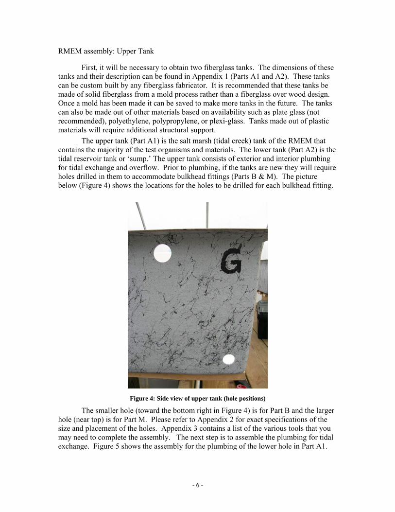
The upper tank (Part A1) is the salt marsh (tidal creek) tank of the RMEM that contains the majority of the test organisms and materials. The lower tank (Part A2) is the tidal reservoir tank or ‘sump.’ The upper tank consists of exterior and interior plumbing for tidal exchange and overflow. Prior to plumbing, if the tanks are new they will require holes drilled in them to accommodate bulkhead fittings (Parts B & M). The picture below (Figure 4) shows the locations for the holes to be drilled for each bulkhead fitting.
Figure 4: Side view of upper tank (hole positions)
The smaller hole (toward the bottom right in Figure 4) is for Part B and the larger hole (near top) is for Part M. Please refer to Appendix 2 for exact specifications of the size and placement of the holes. Appendix 3 contains a list of the various tools that you may need to complete the assembly. The next step is to assemble the plumbing for tidal exchange. Figure 5 shows the assembly for the plumbing of the lower hole in Part A1.

- 7 -
Figure 5: Tidal Exchange plumbing assembly
Insert Part B into the lower hole of the upper mesocosm tank (Part A1). The flange of the Part B should be on the inside of the tank and then assemble the remaining parts as shown in Figure 5. All threaded fittings should be sealed with Teflon Tape (shown in Appendix 3). Figure 6 shows the completed plumbing minus the tubing which will be installed later in the process using a stainless steel hose clamp (Part G).
Figure 6: Tidal Exchange plumbing (exterior) completed
Next, from the interior of the tank (Part A1), assemble the tidal standpipe with strainer as shown in Figure 7.

- 8 -
Figure 7: Tidal Exchange plumbing (interior standpipe).
Part B shown here in Figure 7 is the same Part B from Figure 5. Thread Part C into the flange side of Part B in the interior of the mesocosm. The length of Part J controls the depth at low tide in the mesocosm. Do not glue Part J into Parts I and K. Simply slide them together and seal with a small bead of silicon caulk. The length of this pipe should be tailored to your specific application or experiment. For instance, in some applications it may be preferable to have the water level remain relatively high even during low tide so that test organisms and exposure cages can remain completely submerged. Figure 8 shows the completed standpipe on the interior of the mesocosm.
Figure 8: Tidal Exchange plumbing (interior standpipe) assembled
- 9 -
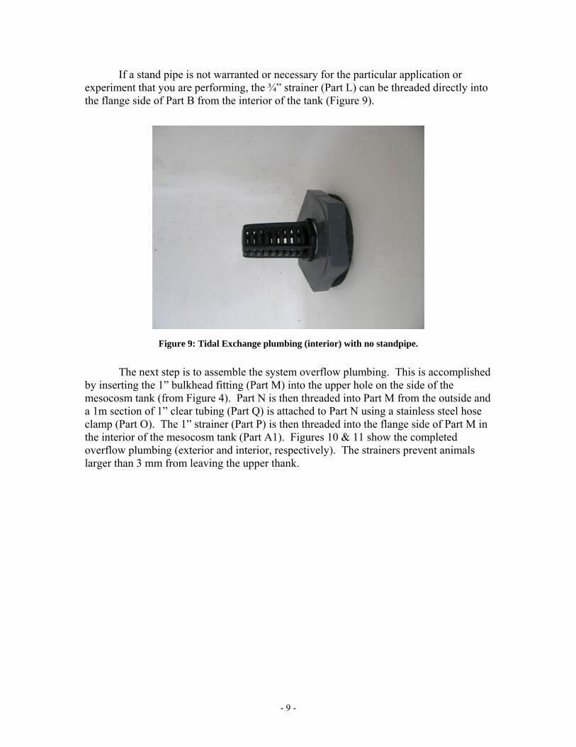
If a stand pipe is not warranted or necessary for the particular application or experiment that you are performing, the ¾” strainer (Part L) can be threaded directly into the flange side of Part B from the interior of the tank (Figure 9).
Figure 9: Tidal Exchange plumbing (interior) with no standpipe.
The next step is to assemble the system overflow plumbing. This is accomplished
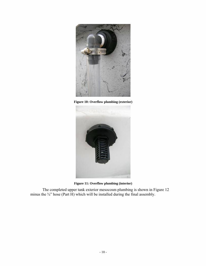
by inserting the 1” bulkhead fitting (Part M) into the upper hole on the side of the mesocosm tank (from Figure 4). Part N is then threaded into Part M from the outside and a 1m section of 1” clear tubing (Part Q) is attached to Part N using a stainless steel hose clamp (Part O). The 1” strainer (Part P) is then threaded into the flange side of Part M in the interior of the mesocosm tank (Part A1). Figures 10 & 11 show the completed overflow plumbing (exterior and interior, respectively). The strainers prevent animals larger than 3 mm from leaving the upper thank.
- 10 -
Figure 10: Overflow plumbing (exterior)
Figure 11: Overflow plumbing (interior)
The completed upper tank exterior mesocosm plumbing is shown in Figure 12 minus the ¾” hose (Part H) which will be installed during the final assembly.

- 11 -
Figure 12: Completed mesocosm plumbing for upper tank

- 12 -
RMEM assembly: Sediment Trays
The next step in the process is to construct the sediment trays (Part R) for containing the inter-tidal sediments. The design and arrangement of these trays can vary depending on the application or experiment. The sediment trays can be arranged to be inter-tidal, sub-tidal, or some combination of the two. This suggested design is suitable and versatile for most inter-tidal sediment applications when deployed into the mesocosms. After trials with variously sized sediment trays, the tray shown below (2 gallon [7.5 L]) has been determined to be the most suitable (Figure 13).
Figure 13: Sediment tray (2 gallon) with drain holes drilled into sides
This sediment tray was chosen because it is of a standard size and can be ordered directly from a manufacturer, a catalog or online vendor. They measure 8”L x 8”W x 8”D and have a support flange around the top. They are typically made of polyethylene. For applications or experiments involving fish or shrimp, four of these tanks will be sufficient. If the focus of the study is rooted vegetation and/or benthic organisms, then use up to six trays per mesocosm.
It will be necessary to drill several drain holes into these sediment trays. First, sub-surface drainage holes (1” diameter) should be drilled into each tray (2 per side, 1 in the bottom, 9 total). The recommended locations of these holes are shown on Appendix 4A. It is important to be consistent in the placement of these holes for all sediment trays. A single hole should be drilled into the center of the bottom of the tray. The subsurface flow holes can be easily drilled using a 1” hole saw and drill. Once the holes are drilled PVC snap rings and fiberglass mesh (Part S) can be inserted into the holes (Figure 14). The excess mesh can then be trimmed from the holes (Figure 15).

- 13 -
Figure 14: PVC Snap rings and fiber glass mesh installed
Figure 15: Sub-surface holes with snap rings and mesh -- completed
Secondly, surface drainage holes (1 ¾” diameter) will need to be drilled into the top corners of each tray (see Appendix 4B). These holes are shown in Figure 16. The purpose of these holes is to allow water to drain and to allow for the free range movement of pelagic organisms. This is especially critical as the tide ebbs from the units so that animals don’t become trapped in the sediment tray. Figure 16 also shows the location of the subsurface drainage hole in the center of the bottom.

- 14 -
Figure 16: Top view of surface drainage holes
These holes can be drilled by drilling from the top-down into the edge of the flange as shown in Figure 17A with a 1 ¾” hole-saw. Care must be taken to secure the tank from spinning as the teeth of the hole saw grab the plastic. It will be necessary to have two hands on the drill motor when sawing the holes. The sediment tray can be clamped down or placed into a jig that would prevent its movement. It is recommended to start all cuts very slowly and proceed with caution using the variable speed drill. Drill down until the hole-saw cuts approximately 1” past the flange and into the side wall (corner) of the sediment tray itself (Figure 17B).
A hand saw should then be used to cut out the piece by cutting into the corner of the side-wall of the tray at the end of the hole-saw cut (Figure 17C). The completed hole is shown in Figures 16 and 17D. Each sediment tray will require four holes, one in each corner. These holes are to be left open and will not have mesh inserts. The tray will eventually be supported by a PVC stanchion pipe which will be discussed later during the final assembly.

- 15 -
A B
C D
A B
C D
Figure 17: Procedure for drilling the surface drainage holes
RMEM assembly: Lower tank (sump) The next step in the process is to prepare the lower tank (Part A2). There are no required modifications to be made to the sump, such as drilling holes or installing plumbing. An optional ¾” bulkhead fitting may be installed in the lower tank fitted with a ¾” gate valve for the purposes of draining the tank, but it is not necessary. The only item that requires assembly is the aeration box (pump support). RMEM assembly: Aeration Box The aeration box (Part T) serves two purposes. First, it serves as a support for the submersible tidal exchange pump (Part U). This keeps the pump off the bottom of the

- 16 -
tank. The height of the box will also control how much water is pumped into the upper tank. Secondly, the box serves as an aeration chamber filled with crushed oyster shells which aid in buffering pH in the systems. It will first be necessary to drill aeration holes into the boxes and lids as shown in Figures 18 and 19. Aeration holes (¼”) should be drilled along the bottom edge of each side of the box and then in a consistent pattern across the lid.
Figure 18: Aeration holes along bottom edge of aeration box.
Figure 19: Aeration hole pattern for aeration box lid.
The next step is to assemble the pump and associated plumbing. The pump can be assembled as shown in Figure 20. The pump must be a submersible aquarium grade pump (magnetically driven) and rated for 250 GPH. Again, remember to use Teflon tape

- 17 -
on the all threaded fittings. The hose (Part H) will be attached later during final assembly.
Figure 20: Submersible pump assembly
Most pumps come equipped with some sort of strainer and filter shown in Figure 20. They also come equipped with a mounting bracket. Remove the mounting bracket from the pump so that it can be mounted onto the aeration box. Drill holes into the lid of the aeration box (in the center region) matching the hole pattern of the pump’s mounting bracket (Figure 21). The bracket can then be mounted with long cable ties (Part X) looped through the holes (Figure 22) and fasten underneath.
Figure 21: Mounting Bracket Hole Pattern

- 18 -
Figure 22: Mounting bracket mounted with cable ties.
The next step is to drill a hole in one end of the aeration box near the base and insert a ¼” aeration hose (Part Y). Install the airstone (Part Z) and fiberglass mesh (Part AA) as shown in Figure 23. The purpose of the mesh is to keep the crushed oyster shells from sifting out of the aeration holes along the bottom edge of the box.
Figure 23: Interior of aeration box
Replace the lid on the box and then attach the pump to the mounting bracket. The final step is to secure the lid to the box using cable ties. This can be done on the four corners and sides by drilling additional holes to thread the cable ties through. The completed aeration box is shown in Figure 24. [Note: Do not attach the lid with the cable ties at this time. This will be done later after the addition of crushed oyster shells in Chapter 3].

- 19 -
Figure 24: Assembled aeration box/pump support
Multiple Systems Up to this point, the construction of a single mesocosm unit has been described. The remainder of this chapter assumes that you have constructed at least six of the aforementioned mesocosm units. Six mesocosms will fit onto a single platform. If you want more than six units you must then expanded by multiples of six. It is the experience of the authors that a minimum of 12 units (2 platforms) is required for most experimental designs. Currently, NOAA’s Center for Coastal Environmental Health and Biomolecular Research has 36 units (6 platforms). Platform Construction / Assembly
The materials and plans for the platforms used to support mesocosm units are shown in Appendices 5-7. It is recommended that someone with advanced carpentry and building skills be employed to construct the platforms. Most of the materials to build them can be purchased at any local builder’s supplier. Each platform will support six RMEM units and the necessary control and aeration infrastructure for those units. All fasteners must be completely seated such that there are no gaps between boards. An important feature of these units is that the fasteners are attached in a three-dimensional arrangement (Figure 25) since there is no room for diagonal support. It is important to make the platforms as level as possible. It may be necessary to use shims under the base of each vertical support in order to level the platform (also shown in Figure 25). In order to access the deck, a set of stairs (Figure 26) can be built on one end of the unit or a set of portable platform stairs (Figure 27) can employed if space is an issue.

- 20 -
Electrical Considerations and Aeration On the opposite end of the platform, it is recommended that the necessary
electrical infrastructure be mounted as shown in Appendix 7 & Figure 28. This will have to be done by a licensed electrician. All circuits should be GFCI protected and in water proof/resistant conduit. Conduit should be accessed from overhead for each bank of receptacles. There should be no wires or wiring on or near the floor of the facility.
The air distribution gang valve can be mounted in a convenient place on the side of the platform. The air pump should be placed underneath the platform so that it is out of the way. It is also recommended that the pump be supported with a block so that it is off of the floor of the greenhouse. Air tubing should be arranged to deliver air to each sump from the gang valve (Figure 29). The air tubing can be run along the side of each unit. They should be neatly arranged such that they do not interfere with daily operation of the mesocosms.
Figure 25: Picture showing the 3-dimensional pin attachment

- 21 -
Figure 26: Stairs added to end of platform
Figure 27: Portable stairs can also be used.

- 22 -
Figure 28: Electrical Timer and Receptacles
Figure 29: Air distribution gang valve
Final Assembly
1. Place six completed upper mesocosm tanks (A1) on the upper level of the platform centering them on the support boards. The lower tanks (A2) can be placed on the bottom level beneath each of the upper tanks (Figure 30).

- 23 -
2. Place the aeration box and pump assembly inside of the lower tank (A2). Install the ¾” tubing (Part H) connecting the exterior tidal exchange plumbing of the upper tank to the pump assembly inside the lower tank.
3. Install the ¼” tubing from the aeration box to the air tubing supply on the gang valve.
4. Position the 1” overflow tubing so that it drains directly back into the lower tank (A2) as illustrated in Figure 31.
Figure 30: Three of six units in place on the platform

- 24 -
Figure 31: Location of 1” and ¾” tubing
5. Plug the power cord for all six submersible pumps into the duplex receptacles that are switched by the multi-event timers. Power cords should run underneath the platforms (under the upper deck) and secured so that they are not touching the floor. They can be easily bundled with cable ties. Leave the power off to the receptacles (using the manual switch on the timer) until the tanks can be filled with water. Do not allow the pumps to run with no water. They will overheat and fail.
6. Place sediment tray stanchions inside of the upper tanks and place sediment trays on top of stanchions. Typically, the sediment trays are placed in the systems after they are filled with sediment and vegetation as required by the study design. Sediment tray stanchions heights should be tailored to the specific experiment or application. They can be made from a 6” diameter PVC pipe (Figure 32) cut to the desired length (height) to elevate the sediment tray. Be sure to cut holes in the sides of the stanchions for water to flow. The stanchions can range in height from 2” to 6” depending on the application or experiment. Four to six sediment trays are used, again, depending on the application.

- 25 -
Figure 32: Sediment tray with 2” and 6” high stanchions.

- 26 -

- 27 -
Chapter 3: Standard Operation Title: GENERAL STANDARD OPERATING PROCEDURE FOR THE
REPLICATED MODULAR ESTUARINE MESOCOSM: MATERIALS COLLECTION, SETUP, EXPERIMENTATION, AND BREAKDOWN
1.0 OBJECTIVE
1.1. This section describes how to setup and run the Replicated Modular Estuarine Mesocosm (RMEM) for ecotoxicological studies.
1.2. Specifically: 1.2.1. How to collect salt marsh sediments 1.2.2. How to collect water for the mesocosm 1.2.3. How to setup and run a mesocosm experiments using RMEM; 1.2.4. How to breakdown and dispose of mesocosm materials once the
experiment has been completed 2.0 HEALTH AND SAFETY
2.1 COLLECTIONS 2.1.1 Typically, water, sediments, and fauna are collected from a
relatively pristine site. Personnel should be aware that this procedure requires walking in mud and water, traveling in boats, and using shovels and lifting, buckets and bins filled with sediment. Personnel should wear hip-boots, chest-waders or wetsuit with boots depending on water depth or preference of the wearer and lifejacket if traveling in boat.
2.1.2 All personnel should follow all state and federal regulations and policies with regard to fieldwork and collections. Collection permits may be required. Follow all safety and security polices of your institution or agency.
2.2 SETUP and EXPERIMENTATION 2.2.1 PPE required for setup is a lab coat or apron, gloves, and some sun
protection since setup activities take place in the greenhouse. 2.2.2 During contaminant addition and sampling of contaminated
mesocosms, individuals should also wear gloves and safety glasses in addition to the items listed in 2.2.1
2.3 BREAKDOWN 2.3.1 PPE required for breakdown is lab coat or apron, gloves, and
safety glasses. 2.4 GENERAL SAFETY ITEMS FOR GREENHOUSE:
2.4.1 Shock Hazard: Due to the use of submersible electric pumps (120V AC power). DO NOT put hands, arms, or any other part of your body in the water of the mesocosm tanks or sumps. These pumps are sealed epoxy pumps, but they are not rated for human interaction. There is the possibility one of the seals on the pumps will fail resulting in serous injury or death. If it is necessary for you to reach into the tanks or sumps (at depth) use a net to reach

- 28 -
into the tank and cut the power off at the fuse panel using proper lock-out/tag-out procedures.
2.4.2 Water and electricity do not mix! Be careful when spraying garden hoses and pumps in and around the greenhouse. All electrical drops are GFCI protected at the fuse panel. Electrical cords for the tidal sump pumps for each mesocosm are located at the far end of each mesocosm platform. Take things outside of the greenhouse to spray or wash them off.
2.4.3 Lightning storms. Leave the greenhouse. Report to your main facility.
2.4.4 All personnel should undergo the following safety training prior to working in the greenhouse: 2.4.4.1 Chemical Hazard Communication Training 2.4.4.2 General Safety Training
2.4.5 All personnel working in the greenhouse should read and be familiar with: 2.4.5.1 Your facility’s Chemical Hygiene Plan 2.4.5.2 Your facility’s Emergency Preparedness Plan 2.4.5.3 Your facility’s Job Hazard Analyses 2.4.5.4 MSDSs for the chemicals to be used in the study.
2.4.6 No chemicals should be stored in the greenhouse. 2.4.7 Individuals should dress accordingly and be prepared to work in
hot and sunny conditions. Wear sunscreen, hat, and other UV protective materials as necessary.
3.0 PERSONNEL/TRAINING/RESPONSIBILITIES
3.1 Any employee who routinely works in the laboratory and is able to walk in mud and water, travel in a boat, and lift objects that could be heavy should be capable of performing this task.
3.2 Training of new staff should be carried out under supervision of an experienced technical employee familiar with this SOP before the employee can work unsupervised.
3.3 Collections: A minimum of two persons is required for water collection and a minimum of three persons is required for sediment collection.
3.4 Setup, experimentation and breakdown: A minimum of two persons is required.
3.5 Personnel should also receive all of your facility’s training courses. Individuals that have not been trained to work in your facility should see the company environmental and safety compliance officer.
3.6 The person responsible for this work should be listed on the exterior door of the greenhouse with emergency contact information. He or she is to be notified immediately of any emergencies or problems therein.
4.0 REQUIRED AND RECOMMENDED MATERIALS
4.1 Sediment Collections (this will require 4 collection trips):
- 29 -
4.1.1 20 buckets (5gallon)/per trip. If each bucket is ½ filled with sediment, there will be enough sediment to fill 4 RMEMs equipped with 6 sediment trays each.
4.1.2 4 shovels 4.2 Water Collection
4.2.1 Water tank (250 gallon) 4.2.2 Large truck 4.2.3 Battery powered submersible pump and deep cycle battery
4.3 Animal Collection 4.3.1 Dip nets 4.3.2 Minnow traps with bait 4.3.3 Buckets 4.3.4 Coolers 4.3.5 Battery powered aeration units with airline tubing and air stones 4.3.6 Waders 4.3.7 Rain coats
4.4 Setup 4.4.1 Sediment trays and stanchions (for elevation) 4.4.2 Homogenized seawater (20ppt)
4.5 Experimentation And Sampling 4.5.1 The exact materials required for dosing and sampling depends
upon the nature of the experiment involved. 4.5.2 Hand-held water quality meter 4.5.3 Sample jars (various – depending on experiment) 4.5.4 Sample vials (various – depending on experiment) 4.5.5 Data notebook/binder 4.5.6 Sample logbook/binder 4.5.7 Contaminant solution for spiking 4.5.8 Carrier solvent for spiking 4.5.9 Pipets 4.5.10 Circulation pumps
4.6 BREAKDOWN 4.6.1 Water hoses (2) with spray nozzles 4.6.2 Pressure Washer 4.6.3 150 gallon tank to be used as a bleach bath 4.6.4 Acid bath 4.6.5 Scrub pads 4.6.6 Siphon hose 4.6.7 Sediment collection device/trap (couple with siphon hose) 4.6.8 55 gallon open head drums (need 5 to 10 of these) with bung
covers. 4.6.9 Shovel
5.0 PROCEDURE
5.1 Mesocosm Preparations Prior to Collection

- 30 -
5.1.1 Plumbing – Reassemble all mesocosm plumbing and valves according to Chapter 1. Make sure that all tidal gate valves are completely opened (Part E).
5.1.2 Pumps (Part U) – reassemble all tidal pumps with elevated oyster shell aeration boxes
5.1.3 Aeration boxes (Part T) – should be pre-filled with commercially available crushed oyster (Figure 33) shell (purchased from a local supplier). The oyster shell should be rinsed several times to remove shell dust.
Figure 33: Filling of aeration box with oyster shells
5.1.4 Place air stone (Part Z) inside of aeration box over the fiberglass
mesh before filling with oyster shell. Assemble the aeration box and secure with cable ties as shown in Figure 24. Be sure to connect the air tubing (Part Y) to the aeration manifold system on the mesocosm platforms. Turn on the air.
5.1.5 Timers – All mesocosm water pumps should be connected to the duplex receptacles that are switched by the timers located at the end of the mesocosm platforms. The timers should be set to switch on and off at desired flood and ebb tides, respectively.
5.1.6 Make sure that all tanks and sumps are centered and aligned on their support structures.
5.1.7 Make sure that all power cords are off of the floor. Use cables ties to coil them and keep them elevated.

- 31 -
5.1.8 Greenhouse louvered intakes – set temperature set point to 65 degrees.
5.1.9 Greenhouse exhaust fans – set temperature set point to 75 degrees. 5.1.10 If warranted by your study, install meteorological data loggers
5.1.10.1 One outside for air temperature and humidity 5.1.10.2 One inside for air temperature and humidity 5.1.10.3 One in tipping rain gauge bucket 5.1.10.4 Install PAR Sensor
5.1.11 Deploy multi-parameter water quality sondes if warranted by the study.
5.2 Collections: General notes -- Seawater should be collected first (Figure 34) and homogenized and diluted using deionzed water to the specified salinity for your experiment. Sediments should be collected next, followed by the animals. Usually the animals are collected or purchased and received 7 to 10 days prior to the beginning of dosing.
Figure 34: Portable seawater collection tank
5.3 Collections: Sediments 5.3.1 Intertidal sediments are collected for each mesocosm from an
appropriate reference site. 5.3.1.1 Sediments should be collected from the mud flat at low-tide
within 2-3 m of the edge of the creek where the tallest stands of Spartina are growing.
5.3.2 Sediments should be chosen to avoid mussels and large crab burrows if possible. Try to choose random, representative plots. Use a shovel to remove the top 2-4 cm of sediment from the mud flat and place into 5 gallon buckets (Figure 35). Fill the 5 gallon buckets only ½ full to prevent injury. Full buckets are quite heavy (50-60 lbs).

- 32 -
Figure 35: Collection of intertidal sediments
5.3.3 Remove any crabs, mussels, or other fauna larger than 5 mm if at
all possible in the field. 5.3.4 Transport the buckets containing the sediments, back to the
laboratory or greenhouse. 5.3.5 The sediments must then by sieved by hand through a 3mm sieve
to remove large fauna, shells and other objects (Figure 36). This will take quite a few individuals working with several sieves.
Figure 36: Sediments being sieved (3mm sieve)
5.3.6 The sediments should then be placed into a 55 gallon polyethylene
drum in batches. Fill the drum to approximately 1/3 capacity (15

- 33 -
gallons) and add 3 gallons of seawater to aid in homogenization. The drum should then be placed on drum rotator and rotated for 1/2 hour to homogenize the sediments (Figure 37).
Figure 37: Sediment homogenization on drum rotator
5.3.7 Once homogenized the sediments can be scooped out and poured
into each sediment tray (Part R) until the sediments overflow out of the surface drainage holes (Figure 38). Be sure that the snap rings and mesh (Part S) are in place on all nine of the subsurface drainage holes. It is desirable for the sediments to have a mound in the middle of the tray making the sediment surface higher in all directions than the surface drainage holes in the corners (Figure 38D).

- 34 -
Figure 38: Filling of the sediment trays with homogenized sediments
5.3.8 Randomly place the sediment trays into the mesocosms onto
appropriate stanchion posts (as per study requirements). This is done by randomly choosing a mesocosm and then filling it with appropriate number of sediment trays for the proposed study (Figure 39).

- 35 -
Figure 39: Sediment trays deployed into mesocosms
5.3.9 Once the trays have been placed into the mesocosms, pump the previously collect seawater into the mesocosm and activate the multi-event timer (tide control). The amount of water to place into each system will vary depending on the experimental design. For most applications, 300L of water is sufficient.
5.3.10 After a few days, the sediments will have settled into the trays. At this point it will be necessary to add more sediment into each tray to make the sediment surface level with or slightly higher than the surface drainage holes in the corners of the trays. This may have to be repeated after another week.
5.4 STOP! LOOK FOR LEAKS – at this point it is imperative that you stop and look for leaks. There will be some. Find them and address them and stop the leaks. Leaks can occur at plumbing joints, tank seams, and cracks in sumps. 5.4.1 To fix leaks at plumbing joints: drain down the tank in question,
disassemble the plumbing joint if threaded, clean away old Teflon tape or other pipe sealant (whatever the case may be) replace with new sealant (preferably Teflon tape) and reassemble the plumbing. Refill the system.
5.4.2 If a mesocosm tank or sump is leaking due to a crack, then the tank will have to be drained, dried out, and repaired. The tank may have to be completely replaced if damage is severe.
5.5 After at least a 2-3 week stabilization period, salt marsh vegetation (purchased from a commercial grower) should be planted into each tray (Figure 40). Typically four 2” plugs of Spartina alterniflora are planted into each sediment tray. Depending on the nature of the experiment sediment plots may be planted with other species of interest or left barren. The plugs should be allowed to acclimate for 2-4 weeks prior to the start

- 36 -
of the test. Inspect for transplant shock and replace shocked plugs if necessary.
Figure 40: 2” plugs of Spartina alterniflora
5.6 Collections: Fauna – Animals should be collected approximately 10 days prior to the start of dosing. The nature of the study and the questions being asked will dictate what animal species are collected. Based on past experience it is best to avoid experiments with oysters, mussels, and fiddler crabs. It is also recommended to avoid experiments with fish, especially Fundulus heteroclitus unless the focus of the study requires their use. Sheepshead minnows (Cyprinidon variegatus) can be used, but it is suggested that only fish that are 0.5 to 1 cm be used for no longer than 28 days. This size class can be purchased from a commercial vendor. Fish tend to have huge appetites, especially F. heteroclitus, and the study should be designed around them and their appetites, otherwise exclude them altogether or they will eat all of your other test organisms. 5.6.1 Animals should be collected from the same general site as where
the sediments were collected. 5.6.2 Collect animals using push nets, dip nets, minnow traps, or seines. 5.6.3 Place collected animals into coolers with air stones and transport
them to the greenhouse. 5.6.4 Place the animals into separate tanks with adequate aeration in the
greenhouse to acclimate them to the conditions there. 5.6.5 Three to four days prior to the start of your dosing count and add
the appropriate numbers of animals to the mesocosms. These numbers will be determined based on your study design and the questions you are asking.
5.6.6 Animals can also be purchased or obtained from a commercial vendor or partner if necessary.

- 37 -
5.7 Dosing: Contaminant addition can be achieved in variety of ways. The best situation will depend on the experimental design and the questions being asked (Figure 41).
Figure 41: Mesocosm dosing
5.7.1 Possible dosing plans
5.7.1.1 The upper tank can be dosed with the nominal concentration based either on the entire volume of water in the system (tank plus sump) or on a specific tidal phase (i.e. low tide volume).
5.7.1.2 The sump can be dosed with the nominal concentration based either on the entire volume of water in the system (tank plus sump) or on a specific tidal phase (i.e. low tide volume).
5.7.1.3 The system can be dosed by spiking the contaminant into the mesocosm itself or into an aliquot of mesocosm water (as shown in Figure 41). The aliquot can then be added back into the system. This method helps to facilitate the mixing of the contaminant.
5.7.1.4 All tanks should be labeled in accordance with your facility’s safety policies. Material Safety Data Sheets (MSDS) should be present.
5.7.2 A toxicity test worksheet describing the concentration of contaminant in each mesocosm should be developed and kept on file.
5.8 Sampling – Biological and chemical samples (Figure 42) should be taken prior to dosing and at predefined intervals after dosing, again this should be done according to the experimental design and the questions being asked. Specific guidance regarding the actual sampling protocols should

- 38 -
be designed for each particular experiment. Care should be taken to avid cross-contaminating between dosed mesocosms and control mesocosms. The preferred method is to establish a sampling routine, whereby, controls are sampled first, then low treatments followed by sequentially higher dosed treatments. Always work from low to high.
Figure 42: Sampling of mesocosm sediments
5.9 Water quality parameter measurements are to be taken daily (Figure 43).
Measurements are typically taken at every sampling time point and at other intervals as required by the study. Data is to be recorded electronically or in a log book and then entered into a database.

- 39 -
Figure 43: Water quality parameter measurements

- 40 -
5.10 All samples taken should be recorded into a Sample Logbook. 5.11 Deionzed water should be added to each system on a regular basis to
maintain tank volume due to evaporation (especially during summer months).
5.12 Experiment Conclusion And Breakdown 5.12.1 Sediments and water are analyzed for contaminated residues and
are to be disposed of according to the current regulations regarding hazardous materials management and waste disposal for your facility.
5.12.2 Smaller mesocosm components (sediment trays, screens, tubing, valves, etc.) are to be cleaned in the following fashion: 5.12.2.1 First remove all scum and mud using a scrub pad or
brush and lots of water. Larger items can be taken outside and hosed off or pressure washed (e.g. sediment trays).
5.12.2.2 All items are to be soaked in a 2-5% bleach bath, overnight.
5.12.2.3 Rinse all items with copious amounts of tap water. 5.12.2.4 Place all non-metal objects into a 10% HCl bath
overnight. (do not place valves into acid bath – they have metals parts).
5.12.2.5 Then rinse again with copious amounts of tap water. 5.12.2.6 Allow components to dry.
5.12.3 The mesocosms tanks and sumps are to be drained, pressure washed, scrubbed out by hand using scrub pads and brushes, and rinsed. 5.12.3.1 Siphon down all of the water and remaining mud, rinse,
scrub, rinse down again, and then siphon out remaining water. It may be necessary to carefully tilt the tanks so that the last remaining water can be siphoned out.
5.12.3.2 Allow water and mud that is siphoned to flow into a sediment trap to retain mud from going down the sewer system. This trap consists of a bucket with small holes inserted into a large plastic bin with a large hole stuffed with mesh screen.
5.12.3.3 Take each tank outside and pressure wash and scrub by hand where necessary. Rinse the units clean.
5.12.3.4 Allow mesocosms to dry. 5.12.4 Clean out all tubing and hoses. 5.12.5 Reassemble everything once clean (See Chapter 2).

- 41 -
6.0 QUALITY CONTROL/QUALITY ASSURANCE 6.1 Personnel should follow good laboratory practices during mesocosm
testing. 6.2 The minimum number of replicates tested should be three.

- 42 -

- 43 -
Chapter 4: Maintenance and Troubleshooting This chapter contains a list of recommendations for routine inspections and troubleshooting problems in with the RMEM systems. Routine Inspections Plumbing Inspect all plumbing on a weekly basis. During setup and
acclimation periods it is critical to identify leaks prior to the start of contaminant exposures. Most repairs only require that a threaded fitting be tightened ⅛ to ¼ of a turn and those are usually easy fixes. In some cases a tank will have to be drained to make the necessary repairs
Electrical Inspect all electrical cords, switches, receptacles, and breaker panel switches on a weekly basis.
- Make sure that all cords are off of the floor. - Arrange all cords and wiring in such a way that they
will not dangle into water or have water dripping on them.
- Greenhouses can be humid places and often condensation on the interior walls of the greenhouse can be an issue. Condensation can cause GFCI protected receptacles to ‘trip.’ To prevent or alleviate condensation, run the greenhouse exhaust fans to reduce the humidity in the greenhouse.
Tubing Inspect all mesocosm tubing on a weekly basis to be sure that there are no clogs. Occasionally plant or animal materials may get accidentally lodged in a tube and restrict or stop the flow.
Aeration Inspect each mesocosm for aeration on a daily basis. Make sure that all pumps are running and that you see bubbles in all of the lower tanks.

- 44 -
Maintenance and Replacement Schedules Plumbing and Aeration At the end of each experiment during the clean up process,
identify plumbing and aeration fittings that need replacement. Acquire those items and make the necessary replacements. Replacement schedule (generally):
1. Gate valves Every 3 years 2. Water Pumps Every 3 years 3. Air Pumps Every 3 years 4. General pipe fittings Every 5 years 5. Tubing Every year
Electrical 1. The fasteners in the breaker panel that secure the breakers should be checked for tightness and tightened down if necessary. This should be done by a certified electrician or a member of your facilities physical plant staff once every 2-5 years.
2. The drive belts for the exhaust fans should be checked for tightness once a month and replaced yearly.
Mesocosm tanks and trays At the end of each experiment inspect each mesocosm tank and tray for damage and wear. Replacement schedule for major mesocosm components:
1. Mesocosm tanks Every 10 years 2. Sediment trays Every 5-10 years 3. Aeration boxes Every 3 years
Greenhouse considerations 1. Replace plastic cover to greenhouse once every 5 years
2. If you have an evaporative cooler or heater, follow the manufactures’ guidelines on maintenance and upkeep.
3. Turn off water supply to greenhouse if freezing conditions are possible and you do not have a source of heat.
Cleaning Greenhouses can become very dirty and moldy in a short amount of time. It may be necessary to remove all tanks from the greenhouse once every few years and pressure wash everything inside and out.

- 45 -
Troubleshooting Problem Solution Tide will not rise 1. Check to make sure that you have AC power going
to the pumps 2. Check to make sure that the timers are set correctly 3. Check to make sure that the ¾” gate valves are
open 4. Check for blockages in tubing 5. Check for clogs in the strainers 6. Repair or replace tidal pump
No Aeration 1. Check to make sure that you have AC power going to the air pump
2. Check to make sure that the valves on the air gang valve are open
3. Make sure that valves to unused systems are closed. 4. Check for blockages in tubing. 5. Repair or replace air pump.

- 46 -
- 47 -
Concluding Remarks
As a final statement, we would like to quote Dr. John Gorrie, a physician and inventor from the mid-1800s in Apalachicola, FL who was the first person to build a functioning ice machine. His invention helped to bring about modern refrigeration which paved the way for significant advances in the public health of our nation. Nonetheless, he put the following disclaimer on his invention:
“Many causes of error have been either unavoidable, uncorrected, or overlooked. Owing to defects of mechanical contrivance and unskilled workmanship, incidental perhaps to every new device and novitiate intercourse with practical mechanics, the machine was not capable of performing all its duties with the accuracy the natural laws involved called for; therefore, I cannot be responsible for… …the irregular performance of the machine, nor can I rely upon the allowance made for errors.” This quote is presented to impress upon the reader that, like the first ice machine,
these RMEM systems have many potential sources of error and variation. Despite the finest skill and diligence to overcome these difficulties, nature often seems to do what-ever it pleases. The best approach to follow is a simple approach. Do not try to answer every question in one, all-inclusive experiment. If you do, you’ll find yourself with a great deal of invested time and money and a great deal of unusable data.
It is recommended that mesocosm researchers follow the guidelines set forth in the workshop proceedings by Giddings et al.[5]. That publication is the Proceedings from the Society of Environmental Toxicology and Chemistry’s Community-level aquatic system studies: interpretation criteria (CLASSIC) workshop held in Germany in 1999. The recommendations described therein stress the importance of keeping things simple and they also outline many of the traps and pit falls of mesocosm research.

- 48 -

- 49 -
References 1. Touart, L.W., Chapter 4: Regulatory Endpoints and the Experimental Design of
Aquatic Mesocosm Tests. , in Aquatic Mesocosm Studies in Ecological Risk Assessment, R. L. Graney, J. H. Kennedy, and J.H.R. Jr., Editors. 1994, Lewis Publishers: Boca Raton, FL. p. 25-33.
2. Clark, J.R. and J.L. Noles, Chapter 6: Contaminant Effects in Marine/Estuarine Systems: Field Studies and Scaled Simulations, in Aquatic Mesocosm Studies in Ecological Risk Assessment, R.L. Graney, J.H. Kennedy, and J.H. Rodgers, Editors. 1994, CRC Press, Inc.: Boca Raton, Florida.
3. Lauth, J.R., et al., A Modular Estuarine Mesocosm. Environmental Toxicology and Chemistry, 1996. 15(5): p. 630-637.
4. Pennington, P.L., et al., Modular estuarine mesocosm validation: ecotoxicological assessment of direct effects with the model compound endosulfan*1. Journal of Experimental Marine Biology and Ecology, 2004. 298(2): p. 369-387.
5. Giddings, J.M., et al. Community-level aquatic system studies: interpretation criteria (CLASSIC). in Community-level aquatic system studies: interpretation criteria (CLASSIC). 2002. Schmallenburg, Germany: SETAC Press.

- 50 -

- 51 -
Appendix 1: Illustrated parts list for the RMEM (Replicated Modular Estuarine Mesocosm) PART
ID Item Quantity Image
A1
Custom fabricated rectangular fiberglass open-top tank (48”L X 24”W X 20”H), with interior white gel coat (food-grade quality with low metal content). Upper tank total capacity 100 gallons
[377.5 Liters].
1
A2
Custom fabricated rectangular fiberglass open-top tank (36”L x 22”W x 26”H), with interior white gel coat (food-grade quality with low metal content). Lower tank total capacity 90 gallons
[337.5 Liters].
1
B PVC bulkhead fitting ¾” FIPT X FIPT 1
C Close nipple, gray (MNPT) PVC schedule 80 ¾” 3

- 52 -
Appendix 1: Illustrated parts list for the RMEM (Replicated Modular Estuarine Mesocosm) PART
ID Item Quantity Image
D PVC Elbow, 3/4" 90 degrees angle, schedule 80, threaded 2
E PVC gate valve ¾” FIPT X FIPT 1
F PVC male tubing adaptor ¾” MNPT X barb insert 2
G Stainless steel hose clamp ½” to 1 ½” size 2

- 53 -
Appendix 1: Illustrated parts list for the RMEM (Replicated Modular Estuarine Mesocosm) PART
ID Item Quantity Image
H Clear vinyl tubing ¾” 1 m
I PVC coupling ¾” MNPT x 1” SLIP 1
J PVC 1” PVC pipe, cut to desired length for appropriate depth, Schedule 40 1 section
K PVC Coupling ¾” FNPT x 1” SLIP
(AKA: female adapter) 1

- 54 -
Appendix 1: Illustrated parts list for the RMEM (Replicated Modular Estuarine Mesocosm) PART
ID Item Quantity Image
L Strainer ¾” MNPT 1
M PVC bulkhead fitting 1" FIPT X FIPT 1
N PVC tubing 90 degree ell 1" barb insert X MNPT, 1
O Stainless steel hose clamp 1” to 2” size 2

- 55 -
Appendix 1: Illustrated parts list for the RMEM (Replicated Modular Estuarine Mesocosm) PART
ID Item Quantity Image
P Strainer 1” MNPT 1
Q Clear vinyl tubing 1” 1 m
R Sediment Tray (2 gallon capacity) 8” x 8” x 8” 4-6

- 56 -
Appendix 1: Illustrated parts list for the RMEM (Replicated Modular Estuarine Mesocosm) PART
ID Item Quantity Image
S PVC snap ring and fiberglass builders mesh
(the snap ring is a section of 1” PVC pipe that is a ¼” thickness with a slot cut into it as shown)
48
T 2 gallon plastic tote box with lid 1
U 250 GPH magnetic drive submersible pump with strainer and filter 1

- 57 -
Appendix 1: Illustrated parts list for the RMEM (Replicated Modular Estuarine Mesocosm) PART
ID Item Quantity Image
V PVC bushing ½” X ¾” 1
W PVC ¾” threaded coupling FNPT x FNPT 1
X Cable ties (preferably black), various sizes 1 pack
Y Clear vinyl tubing ¼” 1 m

- 58 -
Appendix 1: Illustrated parts list for the RMEM (Replicated Modular Estuarine Mesocosm) PART
ID Item Quantity Image
Z Air diffuser, 15 cm, ¼” connector 1
AA Fiberglass mesh (cut to fit interior of Part T) 1

- 59 -
Appendix 2: Location of holes for upper tank. The top hole is for the 1” bulkhead fitting (Part M) and the lower one is for the ¾” bulkhead fitting (Part B) [Not to Scale].

- 60 -
Appendix 3: Illustrated list of tools needed
Item Quantity Image
Adjustable pliers (channel locks) Various sizes
may be necessary
Screw Drivers and Nut Drivers Various sizes
may be necessary
Variable Speed, Reversible, Electric Drill, 1/2” drive 1
Hole saws (you will need an assortment of sizes from 1” to 2 ½”) Various sizes
will be necessary

- 61 -
Appendix 3: Illustrated list of tools needed
Item Quantity Image
Teflon Tape (roll) 2

- 62 -
Appendix 4a: Location of drainage holes for sediment trays (side view).

- 63 -
Appendix 4b: Location of drainage holes for sediment trays (top view).

- 64 -
Appendix 5: Lumber and Hardware Materials list for Mesocosm Platforms
Item Quantity Size Treated Lumber 8 2” x 12” x 8’6” Treated Lumber 4 2” x 6” x 8’6” Treated Lumber 4 2” x 6” x 9’ Treated Lumber 4 2” x 6” x 2’6” Treated Lumber 16 2” x 6” x 4’ Treated Lumber 18 2” x 4” x 3’11” Treated Lumber 18 2” x 4” x 2’10”
Lag Screws / Hex Head / Steel / Hot Dip Galvanized 160 3/8” x 3 ½” Carriage Bolts with 2 flat washers, one lock washer and nut 32 3/8” x 4”
Deck Screws 208 3”

- 65 -
Appendix 6: Mesocosm Platform Drawings

- 66 -
Appendix 6: Mesocosm Platform Drawings

- 67 -
Appendix 6: Mesocosm Platform Drawings

- 68 -
Appendix 6: Mesocosm Platform Drawings

- 69 -
Appendix 6: Mesocosm Platform Drawings

- 70 -
Appendix 6: Mesocosm Platform Drawings

- 71 -
Appendix 6: Mesocosm Platform Drawings

- 72 -
Appendix 7: Illustrated list of Accessories for Mesocosm Platforms
Item Quantity Image
Air pump rated for outdoor use. 1 per platform
Air distribution gang valve
1 gang valve with 6 ports
Clear vinyl tubing ¼” (50’ roll) 2 rolls needed

- 73 -
Appendix 7: Illustrated list of Accessories for Mesocosm Platforms
Item Quantity Image
Hard wired multi-event electrical timer 120v 1 per platform
120 volt AC receptacles (switched by timer), water resistant 3 duplexes

- 74 -
Appendix 7: Illustrated list of Accessories for Mesocosm Platforms
Item Quantity Image
120 volt AC receptacle (not switched by timer), shown furthest to the right in diagram, water resistant
1 double duplex
SWITCHED by TIMER
Multi-Event TIMER
DOUBLE DUPLEX

- 75 -
Appendix 8: Published mesocosm studies 1996 - 2007 Peer Reviewed Journal Articles: Bejarano, A.C.; Pennington, P.L.; DeLorenzo, M.E.; and Chandler, G.T. 2005. Atrazine
effects on meiobenthic assemblages of a modular estuarine mesocosm. Marine Pollution Bulletin 50:1398-1404
Christl, T.J., Pennington, P., DeLorenzo, M., Karnacky, K.J., and Scott, G.I. 2004.
Effect of multiple atrazine exposure profiles on hemocyte DNA integrity in the eastern oyster (Crassostrea virginica). Bulletin of Environmental Contamination and Toxicology. 73:404-410.
DeLorenzo, M. E., J. Lauth, P.L. Pennington, G.I. Scott, and P. E. Ross. 1999. Atrazine
effects on the microbial food web in tidal creek mesocosms. Aquatic Toxicology 46:241-251.
Lauth, J. R., G. I. Scott, D. S. Cherry, and A. L. J. Buikema. 1996. A Modular Estuarine
Mesocosm. Environmental Toxicology and Chemistry 15:630-637. Pennington, Paul L., Marie E. DeLorenzo, Jennifer C. Lawton, Erich D. Strozier, Michael
H. Fulton, and Geoffrey I. Scott. 2004. Modular Estuarine Mesocosm Validation: Ecotoxicological Assessment of Direct Effects with the Model Compound Endosulfan. J Exp. Mar. Biol. Ecol. 298:369-387
Walse, S.S, Pennington, P.L., Scott, G.I., Ferry, J.L. 2004. The fate of fipronil in modular
estuarine mesocosms. Journal of Environmental Monitoring. 6:58-64. Walse, S.S., G.I. Scott and J.L. Ferry. 2003. Stereoselective degradation of aqueous
endosulfan in modular estuarine mesocosms: formation of endosulfan lambda-hydroxycarboxylate. Journal of Environmental Monitoring, 2003, 5, 373–379.
Wirth, E.F., Pennington, P.L., Lawton, J.C., DeLorenzo, M.E., Bearden, D., Shaddrix, B.,
Siversten, S., and Fulton, M.H. 2004. The effects of the contemporary-use insecticide (fipronil) in an estuarine mesocosm. Environmental Polltuion. 131:365-371
Theses and Dissertations: Bejarano, A.C. 2004. Toxicological evaluation of urban-related contaminants in
estuarine ecosystems: 1) effects of contaminants on the development and reproduction of the estuarine copepod Amphiascus tenuiremis; and 2) the role of sediment constituents on pesticide bioavailability to the estuarine bivalve Mercenaria mercenaria. Doctoral Dissertation. University of South Carolina, Norman J. Arnold School of Public Health, Environmental Health Sciences. Columbia, SC.

- 76 -
Christl, T.J. 2004. The ability of P-glycoprotein/multixenobiotic resistance transporter to
respond to two common aquatic contaminants and mitigate resulting toxicities. Doctoral Dissertation. Medical University of South Carolina, Molecular and Cellular Biology and Pathobiology, Charleston, SC.
DeLorenzo, M.E. 1997. Agricultural pesticide runoff in tidal creeks: effects on microbial
food web communities. Doctoral Dissertation. Clemson University, Environmental Toxicology Clemson, SC
Lawton, J. C. 2001. Direct and Indirect Effects of the Herbicide Atrazine on the Clam,
Mercenaria mercenaria. Master's Thesis. University of Charleston, South Carolina, Charleston, South Carolina.
Pennington, Paul L. 2002. The Replicated Modular Estuarine Mesocosm: Assessing
Direct and Indirect Effects of Pesticide Exposure. Doctoral Dissertation. University of South Carolina, Norman J. Arnold School of Public Health, Environmental Health Sciences. Columbia, SC.
Walse, S.S. 2003. Fate of agrochemicals endosulfan and fipronil in model estuarine
environments. Doctoral Dissertation. University of South Carolina, Department of Chemistry. Columbia, SC.

- 77 -

United States Department of Commerce
Carlos M. Gutierrez Secretary
National Oceanic and Atmospheric Administration
Vice Admiral Conrad C. Lautenbacher, Jr. USN (Ret.) Under Secretary of Commerce for Oceans and Atmospheres
National Ocean Service
John (Jack) H. Dunnigan Assistant Administrator for Ocean Service and Coastal Zone Management