the d0 silicon microstrip tracker (d0smt)
DESCRIPTION
The D0 Silicon Microstrip Tracker (D0SMT). Outline Design Detector Studies Coupling capacitors Radiation Damage LASER tests Electronics and readout Mechanical Assembly Production Testing Summary and prospects Installation in the spring of 2000. D0SMT Components. Major SMT Subsystems - PowerPoint PPT PresentationTRANSCRIPT

DD
R. LiptonVertex ‘98 Santorini, Greece
The D0 Silicon Microstrip Tracker (D0SMT)
Outline Design Detector Studies
Coupling capacitors
Radiation Damage
LASER tests Electronics and readout Mechanical Assembly Production Testing Summary and prospects
Installation in the spring of 2000

DD
R. LiptonVertex ‘98 Santorini, Greece
D0SMT Components
Major SMT Subsystems•Single Sided Ladder (3 chip)•Double Sided 2o Ladder (9 chip)•Double Sided 90o Ladder (6 chip)•H Disk (SS back-to-back)•F Disk (DS)

DD
R. LiptonVertex ‘98 Santorini, Greece
Barrel/Disk Module
Title:barrel_f_disk_assy.epsCreator:ImageMagickPreview:This EPS picture was not savedwith a preview included in it.Comment:This EPS picture will print to aPostScript printer, but not toother types of printers.

DD
R. LiptonVertex ‘98 Santorini, Greece
H DISK
• Silicon IR = 94.5 mm, OR = 236 mm at wedge centerlineSilicon IR = 94.5 mm, OR = 236 mm at wedge centerline• Readout mounts on outer silicon detectorReadout mounts on outer silicon detector• Wedges alternate between two surfaces of a central Wedges alternate between two surfaces of a central
cooling/support channelcooling/support channel• Effective stereo angle = 15Effective stereo angle = 15oo
DD
R. LiptonVertex ‘98 Santorini, Greece
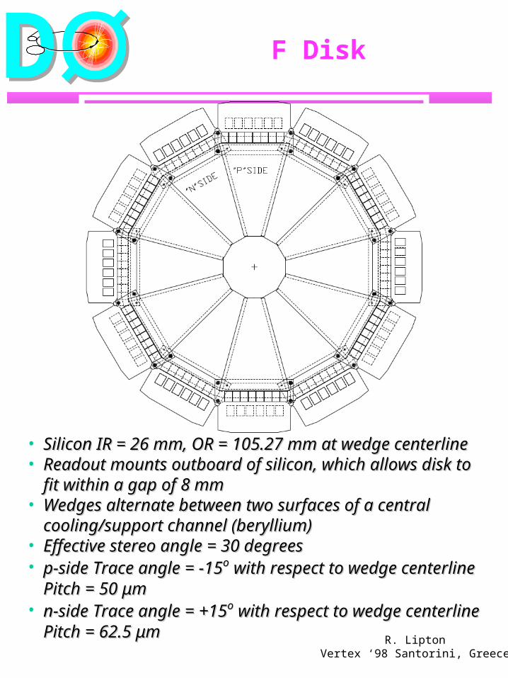
F Disk
• Silicon IR = 26 mm, OR = 105.27 mm at wedge centerlineSilicon IR = 26 mm, OR = 105.27 mm at wedge centerline• Readout mounts outboard of silicon, which allows disk to Readout mounts outboard of silicon, which allows disk to
fit within a gap of 8 mmfit within a gap of 8 mm• Wedges alternate between two surfaces of a centralWedges alternate between two surfaces of a central
cooling/support channel (beryllium)cooling/support channel (beryllium)• Effective stereo angle = 30 degreesEffective stereo angle = 30 degrees• p-side Trace angle = -15p-side Trace angle = -15oo with respect to wedge centerline with respect to wedge centerline
Pitch = 50 μmPitch = 50 μm• n-side Trace angle = +15n-side Trace angle = +15oo with respect to wedge centerline with respect to wedge centerline
Pitch = 62.5 μmPitch = 62.5 μm

DD
R. LiptonVertex ‘98 Santorini, Greece
Capacitor Studies
In a double sided detector with grounded electronics, coupling capacitor breakdown will limit the lifetime of the detector.
Studies Eliminate “black hole” effect in the SVX chip
by bypassing parasitic transistor at the input (see VTX ‘96)
Effect of wirebonding on capacitor breakdown
5-10% of capacitors fail at 50-100V after bonding (normally Vbd=140V) on SS detectors
No excess failures see on DS detectors with PECVD layer
Single Sided Detectors0-100 V
0
20
40
60
80
100
120
0 50 100 150Channels
Vo
lta
ge
bondedunbonded

DD
R. LiptonVertex ‘98 Santorini, Greece
n-side Capacitor Studies
When electronics are connected to the n-side of a detector with shorted capacitors we see an anomalous current from the amplifier input
Current is reduced when electronics is disconnected
Effect seen on n-side only Caused by forward bias of the p-stop n junction
Detector Characteristics
0
2
4
6
8
10
12
14
16
18
0 20 40 60
V Bias
I Bias (microamp)
V Pstop

DD
R. LiptonVertex ‘98 Santorini, Greece
n-side Capacitor Studies
p Stop Study
0
2
4
6
8
10
12
14
16
18
0 10 20 30 40 50 60
V Strip
Istrip (x.1 ma)
V Pstop
50al
p+
n
n+ p+p+
~1VSVX
I strip

DD
R. LiptonVertex ‘98 Santorini, Greece
Irradiation Studies
Expect ~1 Mrad exposure for the inner layer per 4fb1
Irradiation with 8 GeV Protons from the Fermilab booster 1 MeV Neutrons (Lowell Mass.)
Study Evolution of deletion characteristics Performance of detector and electronics
Title:d0-3448.dviCreator:dvipsk 5.66a Copyright 1986-97 Radical Eye Software (www.radicaleye.com)Preview:This EPS picture was not savedwith a preview included in it.Comment:This EPS picture will print to aPostScript printer, but not toother types of printers.

DD
R. LiptonVertex ‘98 Santorini, Greece
Irradiation StudiesCluster size
Title:d0-3448.dviCreator:dvipsk 5.66a Copyright 1986-97 Radical Eye Software (www.radicaleye.com)Preview:This EPS picture was not savedwith a preview included in it.Comment:This EPS picture will print to aPostScript printer, but not toother types of printers.

DD
R. LiptonVertex ‘98 Santorini, Greece
Irradiation Studiesnoise
Title:d0-3448.dviCreator:dvipsk 5.66a Copyright 1986-97 Radical Eye Software (www.radicaleye.com)Preview:This EPS picture was not savedwith a preview included in it.Comment:This EPS picture will print to aPostScript printer, but not toother types of printers.

DD
R. LiptonVertex ‘98 Santorini, Greece
H Disk IrradiationD
eple
tion
volta
ge (
volts
)D
eple
tion
volta
ge (
volts
)NN
effeff
(10
(10
1111 /c
m/c
m33 ))
#3009
0
10
20
30
40
50
60
0 0.5 1 1.5 2 2.5 3
Neutron fluence (10Neutron fluence (101313/cm/cm22))
-8
-6
-4
-2
0
2
4
6
8
10
0.0 0.5 1.0 1.5 2.0 2.5 3.0
Neutron fluence (10Neutron fluence (101313/cm/cm22))

DD
R. LiptonVertex ‘98 Santorini, Greece
Neutron Studies
Title:irrad_map.figCreator:fig2dev Version 3.1 Patchlevel 2Preview:This EPS picture was not savedwith a preview included in it.Comment:This EPS picture will print to aPostScript printer, but not toother types of printers.
Detector Studies using ~1 MeV neutron source

DD
R. LiptonVertex ‘98 Santorini, Greece
Irradiation StudiesLASER Plateau
Title:d0-3448.dviCreator:dvipsk 5.66a Copyright 1986-97 Radical Eye Software (www.radicaleye.com)Preview:This EPS picture was not savedwith a preview included in it.Comment:This EPS picture will print to aPostScript printer, but not toother types of printers.

DD
R. LiptonVertex ‘98 Santorini, Greece
Detector Production
Five detector types - 3-chip, 9-chip, 6-chip, F wedge, H wedge.
All radiation testing complete laser and cosmic ray studies
Measure in-situ rise times charge sharing distributions
Probe testing 100 V capacitor breakdown test on each
channel CV or alpha test to measure depletion IV Test Spot checks on
Interstrip resistance Coupling capacitance Strip currents

DD
R. LiptonVertex ‘98 Santorini, Greece
Micron Detector Delivery
9 Chip DS Ladders
0
100
200
300
400
500
600
8/19/93 11/27/93 3/7/94 6/15/94 9/23/94 1/1/95 4/11/95 7/20/95 10/28/95 2/5/96 5/15/96
Date
de
tec
tors
Micron 9 chip delivered
9 chip schedule
9 Chip Ladder Production
F Disk Wedges
0
20
40
60
80
100
120
140
160
180
200
8/19/93 11/27/93 3/7/94 6/15/94 9/23/94 1/1/95 4/11/95 7/20/95 10/28/95
Date
De
tec
tors
F Disk Wedge Delivered
F Disk Wedge Scheduled
F Disk Wedge Production
Needed forschedule
Needed forschedule

DD
R. LiptonVertex ‘98 Santorini, Greece
Readout System
LOCATING NOTCHES
BERYLLIUM
HDI
SILICON
SVX CHIPS
HDI FLATLINE CABLE
FPGA
Fiber receiver
Fiber Driver
D0 Silicon Readout Scheme
VRBVRBCD0 Clock
System
Trigger Manager
Monitor System
Sequencer Cd (platform)
VME
Fiber Optic Links
Transition Card (cryostat)
pigtail
low mass cable
high mass cable
VBD

DD
R. LiptonVertex ‘98 Santorini, Greece
D0SMT - Electronics
SVXII Chip - done and tested Most issues involve bypassing and clock
quality Needs careful hybrid(HDI) design
HDIs - delivery pacing production Single layer flex 4 mil pitch, 2 mil vias
Cables: low mass, good frequency response (53
Mhz), low attenuation, no reflections, no radiation of clock signal to the calorimeter, fits in the allowed space.
High impedance stripline 3 segments
low mass section of varying length low mass fixed length “high mass” high quality section
System tests underway now

DD
R. LiptonVertex ‘98 Santorini, Greece
Where we were “burned”
HDI flex circuit - good prototypes but no good production circuits
Find reliable company (Dyconex) pay extra $$$
Detector delivery - ordered detectors 2 years early but waited for BABAR, H1…
still a serious problem Cables
low mass, high impedance striplines are difficult pay extra $$$
But we are now in production and expect to be on schedule

DD
R. LiptonVertex ‘98 Santorini, Greece
Mechanical Systems
Design Philosophy Build planar assemblies (ladders, wedges,
disks) precisely under (Zeiss) CMM Use mechanical tolerances to determine
ladder placement in barrel (~15 m) Minimum Mass
Be support structures Carbon fiber overall support

DD
R. LiptonVertex ‘98 Santorini, Greece
Ladder Assembly

DD
R. LiptonVertex ‘98 Santorini, Greece
Module Assembly

DD
R. LiptonVertex ‘98 Santorini, Greece

DD
R. LiptonVertex ‘98 Santorini, Greece
Ladder Assembly
Match notches in Be support to posts in bulkhead
15 micron tolerance on Notched and posts 2 micron tolerances achieved in ladders
0
5
10
15
20
25
30
35
40
-12 -10 -8 -6 -4 -2 0 2 4 6 8 10
Mean = 0.7 micrometers
Sigma = 1.9 micrometers
13 ladders, 78 fiducial locations Detector fiducials relative Detector fiducials relative to beryllium notchesto beryllium notches
Transverse offset from nominal (μmTransverse offset from nominal (μm))

DD
R. LiptonVertex ‘98 Santorini, Greece
Rise Time Studies
Title:d0-3427.dviCreator:dvipsk 5.66a Copyright 1986-97 Radical Eye Software (www.radicaleye.com)Preview:This EPS picture was not savedwith a preview included in it.Comment:This EPS picture will print to aPostScript printer, but not toother types of printers.
Title:d0-3427.dviCreator:dvipsk 5.66a Copyright 1986-97 Radical Eye Software (www.radicaleye.com)Preview:This EPS picture was not savedwith a preview included in it.Comment:This EPS picture will print to aPostScript printer, but not toother types of printers.
Use LASER to excite SSD, Monitor preamp

DD
R. LiptonVertex ‘98 Santorini, Greece
Production Testing
HDI Burn-in Encapsulation
HDI Spot-check Ladder assembly
Ladder Spot-check Ladder repairs
Ladder burn-in LASER Test Insertion into detector
Title:L018.ps (Portrait A 4)Creator:HIGZ Version 1.23/07Preview:This EPS picture was not savedwith a preview included in it.Comment:This EPS picture will print to aPostScript printer, but not toother types of printers.

DD
R. LiptonVertex ‘98 Santorini, Greece
Laser TestingChannel uniformity
Title:scans.dviCreator:dvipsk 5.66a Copyright 1986-97 Radical Eye Software (www.radicaleye.com)Preview:This EPS picture was not savedwith a preview included in it.Comment:This EPS picture will print to aPostScript printer, but not toother types of printers.

DD
R. LiptonVertex ‘98 Santorini, Greece
Laser TestingChannel Gains
Title:scans.dviCreator:dvipsk 5.66a Copyright 1986-97 Radical Eye Software (www.radicaleye.com)Preview:This EPS picture was not savedwith a preview included in it.Comment:This EPS picture will print to aPostScript printer, but not toother types of printers.

DD
R. LiptonVertex ‘98 Santorini, Greece
Ladder and HDI

DD
R. LiptonVertex ‘98 Santorini, Greece
Summary
We have achieved: low mass flex/beryllium hybrids SVX II chip, 53 MHz readout Minimal dead area Precise construction A workable double sided design for
“moderate” radiation doses Now we just have to build another 787,968
channels
%d0%9c%d0%b0%d0%b3 %d0%95%d0%ba%d0%b1 %d0%91%d1%96%d0%be%d1%82%d0%b5%d1%85%d0%bd%d0%be%d0%bb%d0%be%d
%d0%a1%d0%b1%d0%be%d1%80%d0%bd%d0%b8%d0%ba%20%d0%9c%d0%b5%d0%b4 %20%d0%b7%d0%b0%d0%b2 %20%d0%b4%d0%b
%d0%a4%d0%93%d0%9e%d0%a1%203 %20%d0%9b%d0%b5%d1%87%d0%b5%d0%b1%d0%bd%d0%be%d0%b5%20%d0%b4%d0%b5%d0%b
%d0%93%d0%90%d0%a3%d0%97%20%20%d0%a0%d0%9f%d0%a6%20%d0%b3 %d0%a3%d0%bb%d0%b0%d0%bd %d0%a3%d0%b4%d1%8
%d0%9d%d0%b0%d0%b2%d1%87%d0%b0%d0%bb%d1%8c%d0%bd%d0%be %d0%bc%d0%b5%d1%82%d0%be%d0%b4%d0%b8%d1%87%d0
%d0%9f%d0%be%d0%bb%d0%be%d0%b6%d0%b5%d0%bd%d0%b8%d0%b5 %d0%9f%d0%be%d1%81%d0%bb%d1%8b%20%d0%9f%d0%be
%d0%a3%d1%87%d0%b5%d0%b1%d0%bd%d1%8b%d0%b9%d0%9f%d0%bb%d0%b0%d0%bd %d0%a4%d1%83%d0%bd%d0%b4%d0%9c%d0
%d0%a3%d1%87%d0%b5%d0%b1%d0%bd%d0%b8%d0%ba%d0%b8%20%d0%98%d0%b7%d0%b4 %d0%b2%d0%b0%20%d0%9c%d0%98%d0
%d0%9a%d0%b0%d1%82%d0%b0%d0%bb%d0%be%d0%b3 %d0%9c%d0%be%d0%bb %d0%a1%d0%bf%d0%b5%d1%86 %d1%83%d0%ba%
%d0%b5 %d0%b5%d0%ba%d1%80%d0%b0%d0%bd %d0%b4%d0%be%d1%80%d0%b0%d0%bd%d0%b8%d0%ba%d0%b8 %d0%bb%d1%8e%
%d0%9c%d0%b0%d0%b3 %d0%95%d0%ba%d0%b1 %d0%a2%d0%b5%d1%85%d0%bd%d0%be%d0%bb%d0%be%d0%b3%d1%96%d1%97%2
%d0%bf%d1%80%d0%be%d0%b5%d0%ba%d1%82%d0%b8%d1%80%d0%be%d0%b2%d0%b0%d0%bd%d0%b8%d0%b5 %d0%b2%d0%bd%d1