the construction of roads and streets
TRANSCRIPT
l<fe TOALE'S RUDIMENTARY SCIENTIFIC
? AND EDUCATIONAL SERIES.
The following are the Works already published in ^;CIVIL ENGINEERING, &c.
(T& Volumes are bound in limp cloth, except where otherwise stated.)
CIVIL ENGINEERING, the Rudiments of. By HENKY ;
LAW M. Inst. C.E. Including a Treatise on Hydraulic Engi- .
neering. By G. R. BURNBLL, M. Inst. C.E. Seventh Edition, <
revised, with Large Additions on Recent Practice in Civil
Engineering. By D. KINNEAB CLARK, M. Inst. C.E. 6s. 6d. ;!
cloth boards, 7s. 6d.
THE CONSTRUCTION OF GAS-WORKS, ANDTHE MANUFACTURE AND DISTRIBUTION OF COALGAS. Originally written by SAMUEL HUGHES, C.E. Seventh
Edition. Re-written and much enlarged by WILLIAM RICHARDS,
C.E. With numerous Illustrations. 5s. 6d. ; cloth boards, \
6s. cWATER-WORKS, for the Supply of Cities and Towns. !
With a Description of the principal Geological Formations of
England as influencing Supplies of Water ;Details of Engines
and Pumping Machinery for Raising Water. By SAMUEL HUGHES,
F.G.S., C.E. New Edition, revised and enlarged, with numerous
Illustrations. 4s. ; cloth boards, 4s. 6d.
ROADSANDSTREETS(THE CONSTRUCTION OF).In Two Parts. I. The Art of Constructing Common Roads. ByHENRY LAW, C.E. II. Recent Practice in the Construction of
Roads and Streets : including Pavements of Stone, Wood, and
Asphalte. By D. KINNEAR CLARK, M.I.C.E. Third Edition,revised. With numerous Illustrations. 4s. 6d.
;cloth boards, 5s.
EMBANKING LANDS FROM THE SEA, the Prac-tice of. Treated as a Means of Profitable Employment for
Capital. By JOHN WIGGINS, F.G.S. 2s.
LAND AND ENGINEERING SURVEYING, aTreatise on
;with all the Modern Improvements. Arranged for
the Use of Schools and Private Students;
also for Practical
Land Surveyors and Engineers. By T. BAKER, C.E. NewEdition, revised by EDWARD NUGENT, C.E. Illustrated withPlates and Diagrams. 2s. ; cloth boards, 2s. 6d.
SUBTERRANEOUS SURVEYING, an Elementaryand Practical Treatise on. By THOMAS FENWICK, and THOMASBAKER, C.E. Illustrated. 2s. 6d.
;cloth boards, 3s.
MAGNETIC SURVEYING AND ANGULAR SUR-VEYING, with Records of the Peculiarities of Needle Dis-turbances. Compiled from the Results of carefully made Ex-
periments. By WILLIAM LINTERN, Mining and Civil Engineerand Surveyor. 2s.
CBOSBY LOCKWOOD & CO., 7, STATIONEES' HALL COURT, E.G.
1
frfoJ^' gA SELECTION FROM WEALE'S SERIES. ^
SANITARY WORK IN THE SMALLER TOWNSAND IN VILLAGES. Comprising:!. Some of the moreCommon Forms of Nuisance and their Remedies
;2. Drainage ;
3. Water Supply. By CHARLES SLAGG, Assoc. M. .Inst. C.E.
Second Edition, Revised and Enlarged. 3s.;cloth boards, 3s. 6d.
WELLS AND WELL-SINKING. By JOHN GEORGESWINDELL, A.R.I.B.A., and G. R. BURNELL, C.E. Revised
Edition, with an additional Chapter, and a new Appendix on the
Qualities of Water. Illustrated. 2s.
PIONEER ENGINEERING. A Treatise on the
Engineering Operations connected with the Settlement of Waste *K^{Lands in New Countries. By EDWARD DOBSON, Assoc. Inst. jlfC.E. 4s. 6d.
;cloth boards, 5s.
irgj
MATERIALS AND CONSTRUCTION ; a Theoretical &and Practical Treatise on the Strains, Designing, and Erection S$<of Works of Construction. By FRANCIS CAMPIN, C.E. Second iif<Edition, revised. 3s.
;cloth boards, 3s. 6d. JjQ.
3
DICTIONARY OF TERMS used in Architecture, 'cyBuilding, and Engineering ; Mining, Surveying, and Construe- ofation
; Early and Ecclesiastical Art;the Fine Arts, &c. New -if<
Edition, revised and enlarged by ROBERT HUNT, F.R.S. 6s. ; tC;cloth boards, 6s. ?,
DRAWING AND MEASURING INSTRUMENTS. %*- Including I. Instruments employed in Geometrical and Me- ^<'
chanical Drawing, and in the Construction, Copying, and Mea- .JG.surement of Maps and Plans. II. Instruments used for the c ypurposes of Accurate Measurement, and for Arithmetical Com- 2^tputations. By J. F. HEATHER, M.A., late of the Royal Military 3jg.Academy, Woolwich, Author of "Descriptive Gecmstrr," c.~, *Y^:
&c. Illustrated. Is. 6d.jj;
OPTICAL INSTRUMENTS. Including (more especially) 3^Telescopes, Microscopes, and Apparatus for producing copies of -*?",
Maps and Plans by Photography. By J. F. HEATHER, M.A. JTVIllustrated. Is. 6d. T3T
SURVEYING AND ASTRONOMICAL INSTRU- 5&MENTS. Including I. Instruments used for Determining the JLv <
Geometrical Features of a portion of Ground. II. Instruments .pC?employed in Astronomical Observations. By J. F. HEATHEK, r%,M.A. Illustrated. Is. 6d. 3^
MATHEMATICAL INSTRUMENTS. By J. F. $frHEATHER, M.A. Enlarged Edition, for the most part entirely C :
re-written. The 3 Parts, as above, in One thick Volume. With Vnumerous Illustrations. 4s. 6d.
; cloth boards, 5s. ^(kg STATICS AND DYNAMICS, the Principles and Prac- &
tice of; with those of Liquids and Gases. ByT. BAKER, C.E. Si?Third Edition, revised byE. NUOENT. C.E. Illustrated. Is. 6d.
<g,^2 CROSBY LOCKWOOD & CO., 7, STATIONERS' HALL COURT, E.G. j

THE CONSTRUCTIONOF
ROADS AND STREETSIN TWO PARTS
I. THE AET OF CONSTEUCTING COMMON EOADS
BY HENKY LAW, M.I.C.E.
KEVISED AND CONDENSED BY D. KINNEAR CLARK, M.I.C.E.
II. EECENT PEACTICE IN THE CONSTEUCTIONOF EOADS AND STEEETS
INCLUDING PAVEMENTS OP
STONE, WOOD, AND ASPHALTE
BY D. KINNEAR CLARK, M.I.C.E.AUTHOR OP " TRAMWAYS : THEIB CONSTRUCTION AND WORKING ;
" EDITOR OF"STEAM AND THB STEAM ENGINE," "CIVIL ENGINEERING,"" LOCOMOTIVE ENGINES,"
" FUBL : ITS COMBUSTIONAND ECONOMY," ETC. ETC.
Illustrations
THIRD EDITION, CAREFULLY REVISED
LONDON
CROSBY LOCKWOOD AND CO-7, STATIONERS' HALL COURT, LUDGATE HILL
1887
[All rights reserved]

PEEFACE.
THE present work consists of two parts. The first com-
prises "The Art of Constructing Common Eoads," byMr. Henry Law, revised and condensed
;the second
consists of "The Eecent Practice in the Construction of
Eoads and Streets," by Mr. D. Kinnear Clark, C.E., in the
investigation of which he has been indebted for muchmaterial to the excellent Eeports of Lieutenant-Colonel
Haywood, Engineer and Surveyor to the Commissioners
of Sewers of the City cf London. The whole is preceded
by an historical sketch of the subject, also by Mr. Clark.
The City of London is a microcosm of the best and
most varied experience in carriage-way construction,
under the superintendence of the Engineer who has
lucidly described the various structures which have, from
time to time, been laid down and tried, in a catholic spirit,
and has recorded the results of his experience, in a
series of Eeports ranging over a period of thirty years
from 1848 to 1877. Mr. Clark has endeavoured impar-
tially to set forth the merits and disadvantages of the
systems of pavement which have come under his observa-
tion, and he believes that the results of his investiga-
tions will be useful to others.
The varieties of wood pavement and of asphalte
pavement which have been laid in the Metropolismore especially in the City have been fully described
and, it is hoped, fairly criticised. Mr. Clark has also
Vi PREFACE.
added a chapter on the Eesistance to Traction on Common
Roads, in which he has endeavoured to educe the law of
rolling resistance, and has contributed new formulas, with
fresh data.
Appended to the text will be found a portion of a paper
by Sir John Burgoyne on Boiling New-made Eoads;
some valuable extracts from Mr. Frederick A. Paget's
Eeport on Eoad-rolling, containing several interesting
historical facts ;and finally, a table showing the Condi-
tion of Wood and Asphalte Carriage-way Pavements in
the City of London, from a recent Report of Colonel
Haywood.
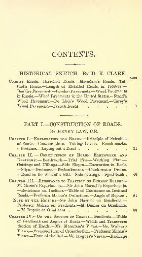
CONTENTS.
HISTORICAL SKETCH. BY D. K. CLAEK.
Country Eoads. BarreUed Roads. Macadam's Roads. Tel-
ford's Roads. Length of Metalled Roads, in 1868-69.
Boulder Pavement. London Pavements. Wood Pavements
in Russia. Wood Pavements in the United States. Stead's
Wood Pavement De TJsle's Wood Pavement. Carey'sWood Pavement. French lioatia
PAET I. CONSTRUCTION OP EOADS.BY HENRY LAW, C.E.
CHAPTER I. EXPLORATION FOR ROADS: Principle of Selection
of Route. Contour Lines. Taking Levels. Bench-marks.
Sections. Laying out a Road 21
CHAPTER II. CONSTRUCTION OP ROADS : EARTHWORK ANDDRAINAGE: Earthwork. Trial Pits. Working Plan.
Onttin^s and "Fillings. Side Slopes. Excavation in Rock.
Slips. Drainage. Embankments. Catch-water Drains.
Road on the Side of a Hill. Side-cuttings. Spoil-bank . 40
CHAPTER III. RESISTANCE TO TRACTION ON COMMON ROADS :
M. Morin's Experiments. Sir John Macneil's Experiments.Resistance on Inclines. Table of Resistance on Inclined
Roads. Professor Mahan's Deductions. Angle of Repose . 61
NOTE BY THE EDITOR: Sir John Macneil on Gradients.
Professor Mahan on Gradients. M.Dumas on Gradients.
M. Dupuit on Gradients 63
CHAPTER IV. ON THE SECTION or ROADS : Gradients. Table
of Gradients and Angles of Roads. Width and Transverse
Section of Roads. Mr. Macadam's Views. Mr. Walker's
Views. Proposed form of Cross Section. Professor Mahan'aViews. Form of the Bed. Mr. Hughes' s Views. Drainage
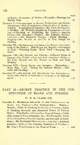
Vli CONTENTS.
PAOBof Roads. Formation of Drains. Footpath. Drainage for
Marshy Soils 65
CHAPTER V. CONSTRUCTION OF ROADS: FOUNDATION AND SUPER-STRUCTURE : Soft Foundations. Classification of Roads.
Solidity. Foundations of Concrete. Mr. Penfold's Practice.
Binding. Mr. Telford's Practice in Foundations. Cover-
ing. Cementing or Solidifying the Surface. AngularStones. Mr. Macadam's Practice. Mr. Telford's Practice.
Gravel. Mr. Hughes's Practice. Chalk Binding.Faggots. Mr. Walker on the Use of Iron Scraps for
Binding 79
CHAPTER VI. ON REPAIRING AND IMPROVING ROADS : Improve-ment of the Surface. Best Season for Repairs. Formationof Mud. Watering Roads. Tools Used. Scraping Ma-chines 93
CHAPTER VII. ON HEDGES AND FENCES : Different Kinds of
Fences. Dry Rubble. Post and Rail. Quickset Hedge.Sir John Macneil and Mr. Walker on Close and HighHedging 104
CHAPTER VIII. PAVED ROADS AND STREETS: Excavation.Stone Sets. Curb. Paving for Inclined Streets. Side-
walks and Crossings 108
CHAPTER IX. ON TAKING OUT QUANTITIES FOR ESTIMATES :
Earthwork. Table of Contents of Cuttings or of Embank-ments ... 114
PAET II. EECENT PEACTICE IN THE CON-STEUCTION OF EOADS AND STEEETS.
BY D. K. CLARK, C.E.
CHAPTER I. MATERIALS EMPLOYED IN THE CONSTRUCTION OPROADS AND STREETS: For Carriage-ways: Stones.
Granite. Table of Crushing Resistance of Granite. Table
of Crushing Strength and Absorbent Power of VariousStones. Trap Rocks. Comparative Wear of Stones. Table
of the Relative Wear of Granites, &c. For Footpaths : Tableof the Composition, Specific Gravity, and Strength of Sand-stones. Mr. Newlands' Observations. Asphalte. Artificial
Asphalte. Table of the Crushing Resistance of Timber.
Mr. Hope's Experiments on the Wear of Wood . . .122
CONTENTS. IX
PAGBCHAPTER II. CONSTRUCTION OF MODERN MACADAM ROADS:
Boning Rods. First-class Metropolitan Roads. Second-
class Metropolitan Roads. Country Roads . . . .134
CHAPTER III. MACADAMISED ROADS WEAR: Weak or " Elas-
tic" Roads. Mr. John Farey on Wear of Roads. Compa-rative Action of Feet of Horses and Wheels of Vehicles.
Sir John Macneil on the Four-horse Stage-coach, and on the
Weight of Vehicles and Width of Tyres on Common Roads.
Mr. James Macadam on Weight of Vehicles and Width of
Tyres. M. Dupuit on Width of Tyres. Mr. Joseph Mit-
chell on the Proportion of Vacuity to Solid Material, in
Broken Stones. Mr. Bokeberg on the same. Mr. Mitchell's
Analysis of the Crust of a Macadam Road. The Road-
roller. Annual Wear of Metalled Roads . . . .138
CHAPTER IV. MACADAMISED ROAF.S COST : Roads in London.
Mr. F. A. Paget's Data, with Table. Suburban Highways.Mr. George Pinchbeck's Data. Local Roads . . .151
Roads in Birmingham. -Mr. J. P. Smith's Data . . .155Streets and Roads in Derby. Mi. E. B. Ellice-Clark's Data.
Table of Macadamised Streets. Table showing Estimated
Cost of Paving. Table of Comparative Costs for Granite
and Macadam . . . . . . . . .158Roads in Sunderland.'Mi. D. Balfour's Data . . . .161Roads in Districts near Edinburgh, Glasgow, and Carlisle. Mr.
J. H. Cunningham's Data 162
CHAPTER V. CONCRETE ROADS: Mr. Joseph Mitchell's Con-
crete Macadam 153
CHAPTER VI. MACADAMISED ROADS IN FRANCE : M. Dumas'Views. Type Sections of Roads 165
CHAPTER VH. STONE PAVEMENTS CITY OF LONDON: Con-
struction of Early Pavements. Colonel Haywood's Reports.Table of Earliest Granite Pavements. Mr. Kelsey on the
Cost for Reparation, with Table. Introduction of Three-
inch Sets. Colonel Haywood's Tables of the Lengths of
London Pavements in 1848, 1851, and 1866. Mr. William
Taylor on the Euston Pavement. Experimental Paving laid
by Colonel Haywood in Moorgate Street, with Tables.
Granites that have been laid in the City of London. Rota-
tion of Granite Paving. Traffic in the City. Duration of
Three-inch Granite Paving in the City, with Table. Colonel
Haywood's Estimate of its Duration and Cost, with Table.
Example of London Bridge. Blackfriars Bridge. Typi-
X CONTENTS.
PAG*
cal Sections and Plans of a Fifty-feet Street for the City.
Southwark Street 169
CHAPTER VIII. STONE PAYEMENIS OF LIVERPOOL : Mr. New-
lands on the Length of Pavement in 1851. Tables of Cost
for Construction of Set Pavements, Boulder Pavements, and
Macadam 193
CHAPTER IX. STONE PAVEMENTS OF MANCHESTER: Early
Boulder Pavements. Mr. H. Royle on Set Pavements. "Use
of Pitch Grduting. Cost. Macadam 198
CHAPTER X. WEAR OF GRANITE PAVEMENTS: In the City
of London, with Tables. Data for Wear and Duration,
with Table 202
CHAPTER XI. STONE TRAMWAYS IN STREETS: Mr. Walker's
Tramways in the Commercial Road. Resistance on Stone
Tramways. Granite Tramways in Northern Italy. Mr.
P. Le Neve Foster, Jun.'s Data. Prices of Work at Milan . 208
CHAPTER XII. Wogp PAVEMENT: Dimensions of Blocks.
Interspaces 215
CHAPTER XIII. CAREY'S WOOD PAVEMENT: Carey's Pave-
ment in the City of London, with Tables of Cost and Dura-
tion. Carey's most recent Practice ..... 217
CHAPTER XIV. IMPROVED WOOD PAVEMENT: First Laid in
the City of London. Construction. Asphalte Grouting.
Objections to the Flooring. Most recent Practice . . 223
CHAPTER XV. OTHER WOOD PAVEMENTS : Ligno-mineralPavement. Asphaltic Wood or Copeland's Pavement.
Harrison's Wood Pavement. Henson's Wood Pavement.
Norton's Wood Pavement. Mowlem's Wood Pavement.
Stone's Wood Pavement. Gabriel's Wood Pavement.Wilson's Wood Pavement. Table of Wood Pavements in
the City of London 228
CHAPTER XVI. COST AND WEAR OF WOOD PAVEMENTS : Cost
in the City of London. Mr. G. J. Crosbie-Dawson's Data.
Mr. EUice-Clark's Data 236
Wear in the City of London. Relation of Wear to Traffic.
Table of Estimated Duration 238
CHAPTER XVIL ASPHALTE PAVEMENTS. First used in Paris.
Mode of Construction in the City of London. Val deTravers Compressed Asphalte Pavement. Val de TraversMastic Asphalte Pavement. Limmer Mastic AsphaltePavement. Barnett's Liquid Iron Asphalte Pavement.
CONTENTS. XI
PAOBTrinidad Asphalte Pavement. Patent British AsphaltePavement. Hontrotier Compound Asphalte Pavement.
Societe Francjaise des Asphaltes. Maestu Compound As-
phalte. Stone's Slipless Asphalte. Bennett's Foothold
Metallic Asphalte. Lillie's Composite Pavement. McDon-nell's Adamantean Concrete Pavement. Granite Pave-
ments with Asphalte Joints. Table showing the Extent of
Asphalte Pavements in the City of London, 1873. Colonel
Haywood's Deductions from his Experience. Table show-
ing Duration and Repair of Asphalte Pavements in the
City of London, at March, 1873. Table showing the Wearof Asphalte Pavements in Proportion to Traffic. Colonel
Haywood's Conclusions as to the Durability of AsphaltePavements. Cost and Terms of Contracts for Asphalte
Pavements, with Table. Val de Travers Asphalte in
Manchester 242
CHAPTER XVIII. OTHER PAVEMENTS : Metropolitan Com-
pound Metallic Paving. Cast-iron Paving. Cellular-iron
Pavement. Artificial Granite Pavement. Compound Woodand Stone Pavement. Concrete Pavement.... 261
CHAPTER XIX. COMPARISON OF CARRIAGE-WAY PAVEMENTS :
Comparative Costs of Pavements. Cost of Yorkshire Pav-
ing-stones. Foot Pavements. Comparative Slipperiness,with Table. Comparative Convenience. Report of Com-mittee of the Society of Arts 264
CHAPTER XX, CLEANSING OP PAVEMENTS: Composition of
Mud. Dr. Letheby's Analysis, with Table. Moisture in
Mud. Cleansing by Machinery and by Manual Labour.
Proportion of Granitic Detritus in Dust from a Granite
Pavement. Comparative Cost of Cleansing Granite andMacadam. Watering with Jet and Hose, with Table Mr.J. Lovick's Experiments. Cleansing in Paris . . . 268
CHAPTER XXI. MOUNTAIN ROADS: Principle of Selection of
Route Major James Browne's Data. Mr. Dobson on Road-
making in New Zealand. Major Browne on the Cost of
Roads in India, and Method of Construction . . . 282
CHAPTER XXII. RESISTANCE TO TRACTION ON COMMON ROADS :
Investigation of Rolling Resistance on Impressible Roads.Work in Compressing the Material. Resistance is In-
versely Proportional to the Cube Root of the Diameter.
M. Morin's Deductions. M. Dupuit's Deductions. M. De-bauve's Data, with Table. Resistance of M. Loubat's Om-nibus. Experiments by Messrs. Eastons and Anderson on
CONTENTS.
wothe Resistance of Agricultural Carts and Waggons. Sir
John Macneil's Experiments on the Resistance of a Stage-
coach, with Tahle. Formula for Resistance of a Stage-
coach. M. Charie-Marsaines on the Performance of Flemish
Horses, withTable. Mr. D. K. Clark's Data . . .290
APPENDICES.
I. ON ROLLING NEW-MADE ROADS. By General Sir John F.
Burgoyne, Bart 301
II. EXTRACTS FROM " REPORT ON THE ECONOMY OP ROADMAINTENANCE AND HORSE-DRAFT THROUGH STEAM
ROAD-ROLLING, WITH SPECIAL REFERENCE TO THE ME-TROPOLIS." By Frederick A. Paget, C.E. . . .309
III. EXTRACT FROM THE REPORT OF COLONEL HAYWOOD, Engi.neer and Surveyor to the Commissioners of Sewers,
City of London, ON THE CONDITION OF WOOD ANDARPHALTE CARRIAGE-WAY PAVEMENTS, ON THE IST
FEBRUARY, 1877 .... 324
INDEX . ,
COTvTSTBUCTIOXOF
EOADS AND STREETS.
HISTORICAL SKETCH.
BY D. K. CLARK, C.E
IN the middle of last century, communication between
towns was difficult. The roads were originally mere foot-
paths, or horse-tracks, across the country, and the few
wheeled carriages in use were of a rude and inefficient
description, for which the roads were wholly unadapted.The roads were necessarily tortuous, every obstacle which
the ground presented being sufficient to turn the traveller
out of his natural direction. Many of these roads were
carried over hills to avoid marshes, which were subse-
quently drained off or dried up ;others deviated from
their direct course in order to communicate with the fords
of rivers now passable by bridges. The inland commerce
of the country was chiefly carried on by transport on the
backs of pack-horses, and the old-fashioned term load,
commonly in use as a measure of weight, is a remnant of
that custom meaning a horse-load. Gradually, the roads
became practicable for the rude carriages of the times,
and they were maintained, though in a very defective
condition, by local taxes on the counties or parishes in
which they were situated. So they remained until turn-
pike-trusts were established by law, for levying tolls from
2 HISTORICAL NOTICE.
persons travelling upon the roads. Several of these trusts
were established previous to 1765, and they subsequently
became general, when the attention of all classes of the
community was directed to the state of the highways.
Bills for making turnpike-roads were passed, every year, to
an extent which seems almost incredible; and, in addition,
every parish was compelled by the force of public opinion,
supplemented by indictments and fines recoverable at
common law against the trustees, when the roads were
not maintained in proper repair. But the turnpikes formed
a cumbrous system : they were trusts in short lengths
about fifteen or eighteen miles and the surveyors em-
ployed appear to have been ill-educated, and were
appointed by favour of the trustees rather than for any
professional knowledge.A long period elapsed before any good system of road-
making was established. The old crooked horse-tracks were
generally followed, with a few deviations to render them
easy ;the deep ruts were filled with stones or gravel of
large and unequal sizes, or with any other materials
which could be obtained nearest at hand. The materials
were thrown upon the roads in irregular masses, and
roughly spread to make them passable. The best of those
roads would, in our time, be declared intolerable. Road-
making, as a profession, was unknown, and scarcely
dreamt of;for the people employed to make the roads and
keep them in repair, were ignorant and incompetent for
their duties. Travelling was uncommon, and funds were
scanty, and higher talent could not be commanded. Engi-
neers, except in cases of special difficulty, such as the con-
struction of a bridge over a deep and rapid river, cutting
through a hill, or embanking across a valley, probably
thought that road-making was beneath their considera-
tion., and it was thought singular that Smeatou should
have condescended to make a road across the valley of
OLD COUNTRY ROAD. O
the Trent, between Markham and Newark, in 1768. At the
same time, civil engineers, according to Sir Henry Parnell,
"had been too commonly deemed by turnpike-trustees as
something rather to be avoided, than as useful and neces-
sary to be called to their assistance." By-and-bye, as
people became sensible of the value of time, easier and
more rapid means of communication than the old roads
were required : improved bridges were built with easier
ascents; and, in some cases, cuts were made to shorten the
distances, though the general lines of the old roads were
preserved. The roads, no doubt, were somewhat im-
proved in this way, but there was no general system or
concert between the district trustees.
Mr. Arthur Young, in his " Six Months' Tour," pub-lished in 1770, writes of some of the roads in the north of
England :
" To Wigan. Turnpike. I know not, in the
whole range of language, terms sufficiently expressive to
describe this infernal road. Let me most seriously caution
all travellers who may accidentally propose to travel this
terrible country, to avoid it as they would the devil, for a
thousand to one they break their necks or their limbs byoverthrows or breakings down. They will here meet with
ruts, which I actually measured four feet deep, and float-
ing with mud only from a wet summer;what therefore
must it be after a winter ? The only mending it receives
is tumbling some loose stones, which serve no other pur-
pose than jolting a carriage in the most intolerable
manner. These are not merely opinions, but facts;for I
actually passed three carts, broken down, in those eighteenmiles of execrable memory."
" To Newcastle. Turnpike.A more dreadful road cannot be imagined. I was
obliged to hire two men at one place to support my chaise
from overturning. Let me persuade all travellers to avoid
this terrible country, which must either disloce te their
bones with broken pavements, or bury them in muddyB2
HISTORICAL NOTICE.
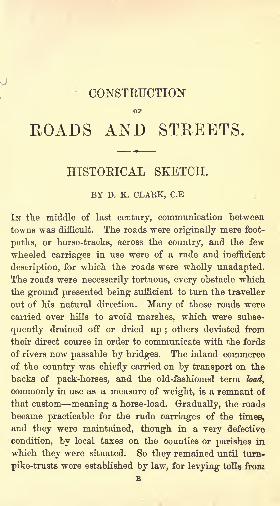
sand." Even so much later as the year 1809, the roads
answered to the description of Mr. Young. Mr. 0. W.
Ward, writing in that year,* states that the convex sec-
tion, as shown in Fig. 1, was the most prevalent in the
Fig. 1. Common Convex Koad, in 1809.
country. Under the impression that the higher the arch
was made, the more easily the road would he drained,
the materials were heaped up about the centre till the
sides became dangerous, by their slope, for the passage of
carriages. The carriages, therefore, ran entirely upon the
middle till it was crushed and worn down, and then a fresh
supply of materials was laid on, and the road was again
restored to its dangerous shape. The sides of the road
were but little used, except in summer, or until the heavy
waggons had crushed the middle into a surface apparently
compact and smooth. In some places, the rough materials
were laid in a narrow line, not exceeding seven or eight
feet in breadth, along the middle of the road, and the
sludge collected from the scrapings of the roads or
ditches was placed on each side, like banks, to prevent the
stones from being scattered by the wheels. The high con-
vex form was so exceedingly defective as to defeat the
object for which it was constructed. Carriages were forced,
for safety or for convenience, to keep to the middle, and
it was speedily ploughed into deep ruts, which held the
rain-water, even when the convexity approached to the
form of a semicircle. The central elevation, therefore,
was not kept dry ;and the central pressure of the traffic
forced the material upon the sides, where they lay loose
* Third Report from Parliamentary Committee on Turnpikes and
Highways, 1809.
OLD COUNTRY ROAD. 5
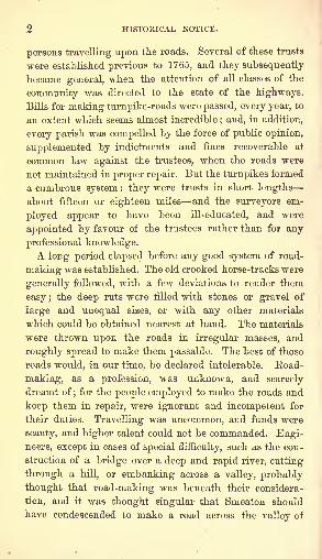
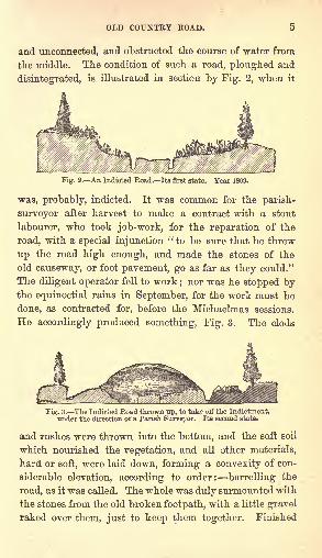
and unconnected, and obstructed the course of water from
the middle. The condition of such a road, ploughed and
disintegrated, is illustrated in section by Fig. 2, when it
Fig. 2. An Indicted Road. Its first
was, probably, indicted. It was common for the parish-
surveyor after harvest to make a contract with a stout
labourer, who took job-work, for the reparation of the
road, with a special injunction "to be sure that he threw
up the road high enough, and made the stones of the
old causeway, or foot pavement, go as far as they could."
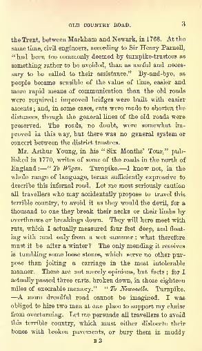
The diligent operator fell to work;nor was he stopped by
the equinoctial rains in September, for the work must be
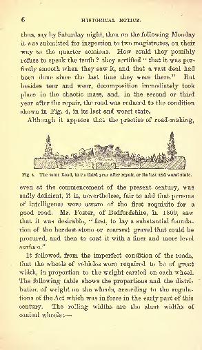
done, as contracted for, before the Michaelmas sessions.
He accordingly produced something, Fig. 3. The cloda
Fig. 3. The Indicied Road thrown up, to take otf the Indictment,under the direction of a Parish Surveyor. Its second state.
and rushes were thrown into the buttom, and the soft soil
which nourished the vegetation, and all other materials,
hard or soft, were laid down, forming a convexity of con-
siderable elevation, according to order: barrelling the
road, as it was called. The whole was duly surmounted with
the stones from the old broken footpath, with a little gravel
raked over them, just to keep them together. Finished
6 HISTORICAL NOTICE.
thus, say by Saturday night, then on the following Mondayit was submitted for inspection to two magistrates, on their
way to the quarter sessions. How could they possibly
refuse to speak the truth ? they certified" that it was per-
fectly smooth when they saw it, and that a rast deal had
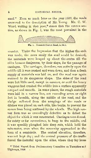
been done since the last time they were there." But
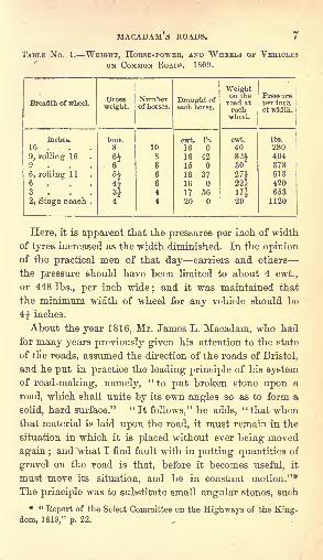
besides tear and wear, decomposition immediately took
place in the chaotic mass, and, in the second or third
year after the repair, the road was reduced to the condition
shown in Fig. 4, in its last and worst state.
Although it appears that the practice of road-making,
Fig. 4. The same Eoad, in its third year after repair, or its last and -worst state.
even at the commencement of the present century, was
sadly deficient, it is, nevertheless, fair to add that personsof intelligence were aware of the first requisite for a
good road. Mr. Foster, of Bedfordshire, in 1809, saw
that it was desirable, "first, to lay a substantial founda-
tion of the hardest stone or coarsest gravel that could be
procured, and then to coat it with a finer and more level
surface."
It followed, from the imperfect condition of the roads,
that the wheels of vehicles were required to be of great
width, in proportion to the weight carried on each wheel.
The following table shows the proportions and the distri-
bution of weight on the wheels, according to the regula-
tions of the Act which was in force in the early part of this
century. The rolling widths are the slant widths of
conical wheels :
MACADAM S ROADS.
TABLE No. 1. WEIGHT, HORSE-POWER, AND WHEELS OP VEHICLES
ON COMMON ROADS. 1809.
Breadth of wheel.
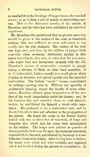
8 HISTORICAL NOTICE.
0.8 resulted from the breakage of larger stones, for rounded
stones;so as to form a sort of mosaic or interlocking sys-
tem. This is the distinctive novelty of the system of
Macadam, and its value has been established by universal
experience.
Mr. Macadam also maintained that no greater convexity
should be given to the surface of the road, in transverse
sections, than was sufficient to cause rain-water to run
readily into the side channels. The surface of the road
was kept even and clean by the addition of proper fresh
materials when necessary, distributed equally in thin
layers immediately after rain, in order that the new mate-
rials might bind and incorporate properly with the old.
Macadam's system of construction consisted in simply
laying a stratum of flints, or other hard materials, 10
or 1 1 inches thick, broken equally into small pieces about
2 inches in diameter, and spread equally over the intended
road-surface. The broken "metal" became consolidated
by carriages passing over it. Without any specialty of
professional training, except the faculty of acute obser-
vation, Macadam eifected great improvement of the sur-
face of the roads immediately under his charge ; and, byhis business-like and extended views on road - adminis-
tration, he established for himself a world -wide repu-tation. He professed to be a road-maker only, and he
devoted his whole time and attention to the propagation of
his system. He found the roads in the Bristol district
loaded with two or three feet of materials, of large and
irregular size, which had for years been accumulated
on the surface. The heaps were utilised as quarries of
stones partially broken on the spot ;the stones he excavated,
separated from the mud, and reduced by breakage to a uni-
form size, 6 ounces in weight. After having been so broken,the stones were relaid, and were carefully and regularlyraked and levelled during the process of consolidation. In
TELFORD'S ROADS. 9
this way, with the addition of effective drainage where
necessary, he was enabled to make a good surface on roads
which previously were almost impassable. As nearly every
road had more metal upon it than was necessary, he, and
the surveyors appointed by him, established economy in
the construction and maintenance, as well as in the admi-
nistration of the finances, and his system became generally
adopted.
Whilst Mr. Macadam deserved well as the pioneer of
good road-construction, it may be observed that he had
been anticipated in the promulgation of the system of a
regularly broken -stone covering by Mr. Edgeworth, an
Irish proprietor, whose treatise on roads, of which the
second edition was published in 1817,* contains the results
of his experiments on the construction of roads, with some
useful rules. He advocated the breaking of the stones to
a small size, and their equal distribution over the surface.
He also recommended that the interstices should be filled
up with small gravel or sharp sand a practice which,
though it was condemned by Macadam, is now adopted
by the best surveyors.
Since Macadam's time, the practice of road-making has
been greatly improved by the use of the roller for com-
pressing and settling new materials, and of preparing at
once a comparatively smooth and hard surface for traffic.
Telford first directed his attention in 1803-4, to the
construction of roads. He was employed chiefly in the
construction of new roads hundreds of miles of roads in
the Scottish Highlands ;also the high road from London
to Holyhead and Liverpool, and the great north roads,
formed in consequence of the increased communication
with Ireland after the Union, and which were excellent
models for roads throughout the kingdom. Telford set
* " An Essay on the Construction of Roads and Carriages," 2nd
edition, 1817.
B3
10 HISTORICAL NOTICE.
out the roads according to the wants of the district through
which they were made, as well as with a view to more
distant communication;and the acclivities were so laid
out, that horses could work with the greatest effect for
drawing carriages at rapid rates. As a notable instance
of the wonderful improvements that were effected by Tel-
ford's engineering skill applied to the laying out of new
roads, an old road in Anglesea rose and fell between its
extremities, 24 miles apart, through a total vertical heightof 3,540 ft.; whilst a new road, laid out by Mr. Telford
between the same points, rose and fell only 2,257 ft., or
1,283 ft. less than the undulations of the old road, whilst
the new road was more than 2 miles shorter.
The road was formed by a substratum, or rough hand-
set pavement, of large stones as a foundation, with suffi-
cient interstices between the stones for drainage. The
materials laid on this foundation were, like Macadam's
materials, hard and angular, broken into small pieces, de-
creasing in size towards the top, where they formed a fine
hard surface, whereon the carriage wheels could run with
but little resistance. Telford's system was afterwards
studied by his assistant, Mr. (afterwards Sir John) Macneil.
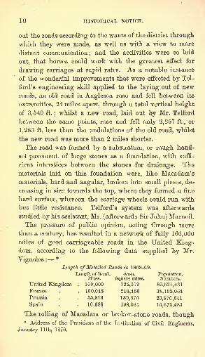
The pressure of public opinion, acting through morethan a century, has resulted in a network of fully 160,000
miles of good carriageable roads in the United King-dom, according to the following data supplied by Mr.
Vignoles:*
Length of Metalled Roads in 1868-69.
Length of Eoad. Area. Population.Miles. Square miles. Numbers.
United Kingdom . 160,000 122,519 30,621,431France . . 100,048 210,460 38,192,064Prussia . . 55,818 139,675 23,970,641
Spain . . 10,886 198,061 16,673,481
The rolling of Macadam or broken-stone roads, though* Address of the President of the Institution of Civil Engineers,
January llth, 1870.
BOULDER PAVEMENT. 11
it seems to have been first applied in 1830, appears to
have been but imperfectly appreciated in England until
about the year 1843, when, according to Mr. F. A. Paget,
the first published recommendation in the English lan-
guage of horse road-rolling, as a measure of economy, was
issued by Sir John Burgoyne.* Road-rolling is now very
generally practised, by horse-power or by steam-power, f
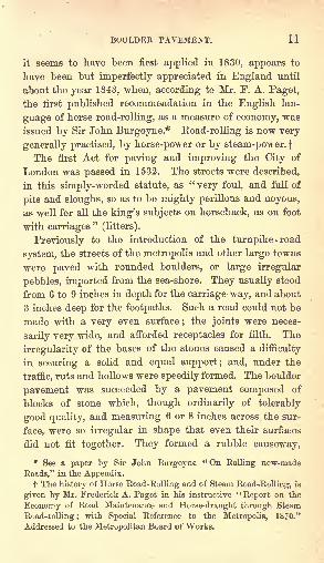
The first Act for paving and improving the City of
London was passed in 1532. The streets were described,
in this simply-worded statute, as "very foul, and full of
pits and sloughs, so as to be mighty perillous and noyous,
as well for all the king's subjects on horseback, as on foot
with carriages"
(litters).
Previously to the introduction of the turnpike -road
system, the streets of the metropolis and other large towns
were paved with rounded boulders, or large irregular
pebbles, imported from the sea-shore. They usually stood
from 6 to 9 inches in depth for the carriage-way, and about
3 inches deep for the footpaths. Such a road could not be
made with a very even surface;the joints were neces-
sarily very wide, and afforded receptacles for filth. The
irregularity of the bases of the stones caused a difficulty
in securing a solid and equal support; and, under the
traffic, ruts and hollows were speedily formed. The boulder
pavement was succeeded by a pavement composed of
blocks of stone which, though ordinarily of tolerably
good quality, and measuring 6 or 8 inches across the sur-
face, were so irregular in shape that even their surfaces
did not fit together. They formed a rubble causeway,
* See a paper by Sir John Burgoyne "On Rolling new-made
Roads," in the Appendix.t The history of Horse Road-Rolling and of Steam Road^Rolling, is
given by Mr. Frederick A. Paget in his instructive "Report on the
Economy of Road Maintenance and Horse-draught through Steam
Road-rolling ;with Special Reference to the Metropolis, 1870."
Addressed to the Metropolitan Board of Works.
12 HISTORICAL NOTICE.
in which the stones were but slightly hammer-dressed.
Wide joints were made;and far from being dressed
square down from the surface, they most frequently only
came into contact near the upper edges; and, tapering
downwards, their lower ends were narrow and irregular,
leaving an insufficient area of flat base to support weight.
With such irregular forms, considerable spaces were un-
avoidably left between the stones, which were filled bythe paviours with loose mould, sand, or other soft material,
of which the bed or subsoil was composed. Another great
deficiency in the construction of the pavement, was caused
by inattention to the selection and arrangement of the
stones according to size large and small stones were
placed alongside of each other, and, as they acted un-
equally in their resistance to pressure, they created a con-
tinual jolting in wheel-carriages, and, adding percussive
action to pressure, became powerful destructive agents.
Again, the bed on which the stones were placed, beingloose matter, for the most part, was easily converted into
mud when water sank through between. It was unavoid-
ably loosened by the paviour's tool, to suit the varying
depths and narrow bottoms of the stones, and to fill upthe chasms between the stones. The mud was worked upto the surface, and the stones were left unsupported. In
consequence of these defects, the surface of the pavementsoon became very uneven, and not unfrequently sunk so
much as to form hollows, which rendered it not onlyincommodious but dangerous to horses and carriages.
Such was the system of pavement met with in London
fifty years ago. Mr. Telford, in 1824, clearly pointed out
the deficiencies of the system ;and in his Report (referred
to in the foot-note)* he recommended first, a bottoming,
* See Mr. Telford's "Report respecting the Street Pavements, &c.,
of the Parish of St. George's, Hanover Square," printed in Sir HenryParnell's "Treatise on Roads," p. 348, 2nd Edition.
LONDON PAVEMENTS. 13
or foundation, of broken stones, 12 inches deep ; second,
rectangular paving-stones of granite, worked flat on the
face, straight and square on all the sides, so as to joint
close, with a base equal to the face, forming, in fact, an
ashlar causeway. The dimensions of the stones were
recommended to be as follows :
Wid'h. Dep'h. Length.Inches. Inches. Inches.
Tor streets of the 1st class 6 to 7j 10 11 to 13
2nd 6 to 7 9 9 to 12
3rd 4 to 6 7 to 8 7 to 11
Stones of such dimensions as those recommended by
Telford, frequently having- a depth of 12 inches, have
been generally employed in street -paving. In some
instances, they have been laid on concrete, with the joints
grouted with lime and sand, to insure a great degree of
stability. They have been proved to possess great dura-
bility of which many instances will be adduced but
they have been, for several reasons, generally abandoned
in favour of narrower paving-stones, 3 or 4 inches in
width, though many secondary streets in London and else-
where, remain, at this day, paved with 6-inch stones.
Macadam's system was introduced in some streets where
the traffic was light, but it did not equal the granite
paving.Pavements formed of blocks of wood appear to have
been first employed in Eussia, where, according to the
testimony of Baron de Bode,* it has been, though rudely
fashioned, used for some hundreds of years. After longand repeated trials of various modes of construction, wood
pavement consisted, according to the approved method, of
hexagonal blocks of fir wood, 6 inches across and 7 inches
deep, planted, with the fibre vertical, close to each
other, on a sound and level bottom;a boiling mixture of
" Wood Pavement," by A. B. Blackie, 1842.
14 HISTORICAL NOTICE.
pitch and tar was poured over them, and a small quantity
of river sand was strewed over the tar." The fabrication
of these blocks," wrote Baron de Bode, "is extremely
simple and expeditious. It is accomplished by fastening
six strong blades into a strong bottom of cast-iron, and
pressing the ready-cut pieces of wood through these six
blades by means of a common or hydraulic press. The
bottom of the press being open, these cut blocks drop on
the floor, completely formed for immediate use. Bed fir
is considered the best;but none of it must be used when
it has blue stripes on its edges, as that is a proof that it
is in a state of decay. The blocks must be perfectly dried
before they are used, and squeezed as close together as
possible between the abutments, one on each side of the
street or road, so as to keep the pavement from moving."In Norway, Sweden, Denmark, and Iceland, wood was, at
the time of Mr. Blackie's writing, and it may be now, in
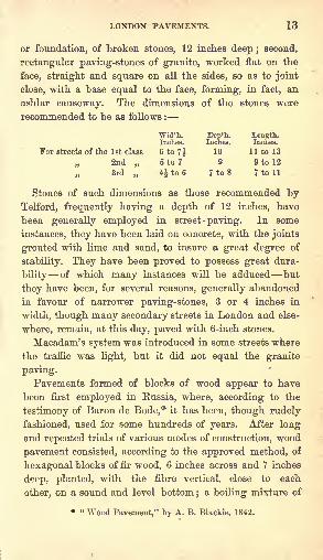
general use for the pavement of streets and highways.In the United States, likewise, wood pavement was laid
down experimentally in New York in 1835-6, and about
the same time in Philadelphia. In New York, it was laid
in three different forms. A hundred yards was laid in
Broadway, consisting of hexagonalblocks of pitch-pine, 6 inches across,
and & inches deep. No pitch or tar
was applied to this pavement : it was
simply strewed occasionally with gravel
or sand for a month after it was laid.
I* had I 8"1 f r *wo years, according to
report, without having required any
repair ; though it appears that very few carts passing over
it carried more than half a ton of load, of which the widest
wheel did not exceed three inches in width. An equal
length of pavement was laid in William Street, a minor
thoroughfare in the end of 1836; the pavement consisted
WOOD PAVEMENT. 15
of 6-inch square blocks of pine, 12 inches deep. Thethird specimen was laid in Mill Street, in the middle of
1837, consisting of the same size and kind of blocks as
those laid in William Street, on a foundation of sand
beat down very hard. It is stated in Mr. Blackie's
pamphlet that the pavement of square blocks was laid on
boards probably in William Street.
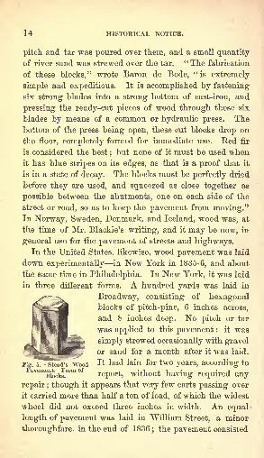
Mr. David Stead was the first constructor of wood
pavement in England. He patented his system in May,1838: consisting of hexagonal blocks of Scotch fir or
Norway fir, from 6 to 8 inches across, and from 3 to
6 inches deep, according to the traffic of the thoroughfare in
which they were to be laid. Each block was of the form
shown in Fig. 5, chamfered at the upper edges. The
ground having been well beaten and levelled, it wascovered with three inches of gravel, upon which the
blocks were placed, and which was designed to carry
away the water which might penetrate below the surface.
The pavement, when completed, looked substantial, and
presented the appearance shown in Fig. 6. When the
blocks were grooved across, they appeared together as in
Fig. 7. Mr. Stead's pavement was,
in several instances, laid on a bed
of concrete. In Manchester, where
it was thus laid, in front of the
Royal Infirmary, the concrete bed
was three inches deep, and was
composed of three parts of small
broken stones, f inch in diameter, P^ e
flushed with Ardwick lime and Stead's Wood Pavement, i&ss.
Roman cement. The lime was mixed with sand in the
proportion of one to two;
and the cement as one to
twenty. The concrete was laid upon a hard, well-beaten
clay substratum.
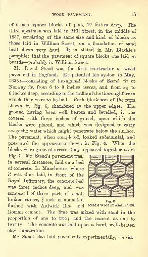
Mr. Stead also laid pavements experimentally, consist-
16 HISTORICAL NOTICE.
ing of round blocks of wood sections of trees placed
vertically, and laid together as in Fig. 8. The interspaces
were filled with sifted gravel or sharp sand.
The first example of wood-pavingin London, was laid in the Old
Bailey, in 1839, on Stead's system.It was laid haphazard on the bed
of the roadway. The pavement did
not wear well;the blocks settled
down irregularly in the unprepared
stead's Wood^avement, 1838. foundation. At the end of three
years and two months, in 1842, the pavement was lifted,
and removed to pave the yard of the Sessions House;
there it decayed, and a large crop of fungi appeared in the
places not touched by the traffic.
Mr. Stead's system of wood pavingwas laid in several other localities in
London about the same time as the
piece which was laid in the Old
Bailey, and also in Woolwich Dock-
yard. It was laid also in Salford,
Liverpool, and Leeds.
Shortly after Mr. Stead's attempt,
during the period from 1840 to 1843,
seven other wood pavements, of various design, were laid
in the City ;but they did not last, for the most part, more
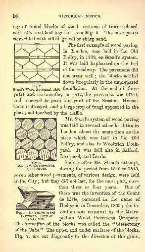
than three or four years. One of
these was the invention of the Count
de Lisle, patented in the name of
Hodgson, in December, 1839;the in-
vention was acquired by the Metro-
politan "Wood Pavement Company.The formation of the blocks was called the "Stereotomyof the Cube." The upper and under surfaces of the blocks,
Fig. 9, are cut diagonally to the direction of the grain,
Kg. 8.
Stead's Wood Pavement.Round Blocks.
Fig. 9. De Lisle's WoodPavement. Form of
Blocks, 1839.
WOOD PAVEMENT. 17
Fig. 10. De Lisle's WoodPavement, 1839.
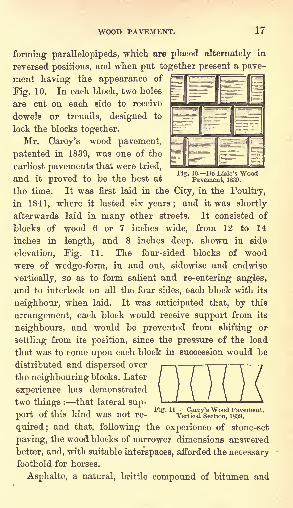
forming parallelepipeds, which are placed alternately in
reversed positions, and when put together present a pave-
ment having the appearance of
Fig. 10. In each block, two holes
are cut on each side to receive
dowels or trenails, designed to
lock the blocks together.
Mr. Carey's wood pavement,
patented in 1839, was one of the
earliest pavements that were tried,
and it proved to be the best at
the time. It was first laid in the City, in the Poultry,
in 1841, where it lasted six years; and it was shortly
afterwards laid in many other streets. It consisted of
blocks of wood 6 or 7 inches wide, from 12 to 14
inches in length, and 8 inches deep, shown in side
elevation, Fig. 11. The four-sided blocks of wood
were of wedge-form, in and out, sidewise and endwise
vertically, so as to form salient and re-entering angles,
and to interlock on all the four sides, each block with its
neighbour, when laid. It was anticipated that, by this
arrangement, each block would receive support from its
neighbours, and would be prevented from shifting or
settling from its position, since the pressure of the load
that was to come upon each block in succession would be
distributed and dispersed over
the neighbouring blocks. Later
experience has demonstrated
two things : that lateral sup-
port of this kind was not re-Fig. 11 Carey's Wood i'avement.
Vertical Section, 1839.
quired; and that, following the experience of stone-set
paving, the wood blocks of narrower dimensions answered
better, and, with suitable interspaces, afforded the necessary
foothold for horses.
Asphalte, a natural, brittle compound of bitumen and
18 HISTORICAL NOTICE.
limestone, found in volcanic districts, was introduced from
France, for foot-pavements, in 1836. It lias, since that
time, been extensively employed in the City of London for
the pavements of carriage-ways.
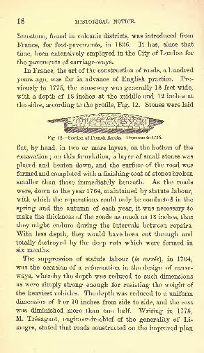
In France, the art of the construction of roads, a hundred
years ago, was far in advance of English practice. Pre-
viously to 1775, the causeway was generally 18 feet wide,
with a depth of 18 inches at the middle and 12 inches at
the sides, according to the profile, Fig. 12. Stones were laid
af French Roads. Previous to 1775.
flat, by hand, in two or more layers, on the bottom of the
excavation;on this foundation, a layer of small stones was
placed and beaten down, and the surface of the road was
formed and completed with a finishing coat of stones broken
smaller than those immediately beneath. As the roads
were, down to the year 1764, maintained by statute labour,
with which the reparations could only be conducted in the
spring and the autumn of each year, it was necessary to
make the thickness of the roads as much as 18 inches, that
they might endure during the intervals between repairs.
With less depth, they would have been cut through and
totally destroyed by the deep ruts which were formed in
six months.
The suppression of statute labour (la corvte), in 1764,
was the occasion of a reformation in the design of cause-
ways, whereby the depth was reduced to such dimensions
as were simply strong enough for resisting the weight of
the heaviest vehicles. The depth was reduced to a uniform
dimension of 9 or 10 inches from side to side, and the cost
was diminished more than one half. Writing in 1775,
M. Tresaguet, engineer-in-chief of the generality of Li-
moges, stated that roads constructed on the improved plan
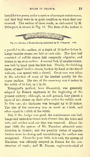
ROADS IN FRANCE. 19
lastedfor ten years, under a system of constant maintenance,
and that they were in as good condition as when first con-
structed. The section of these roads, as elaborated by M.
Tresaguet, is shown in Fig. 13. The form of the bottom is
Fig. 13. Section of French Roads, elaborated by M. Tre"sa#uet. 1775.
a parallel to the surface, at a depth of 10 inches below it.
Large boulder stones are laid at each side. The first bed
consisted of rubble stones laid compactly edgewise, and
beaten to an even surface. A second bed, of smaller stones,
was laid by hand upon the first bed. Finally, the finishing
layer, of small broken stones, broken by hand to the size of
walnuts, was spread with a shovel. Great care was taken
in the selection of stone of the hardest quality for the
upper surface. The rise of the causeway was 6 inches in
the width of 18 feet, or 1 in 36.
Tresaguet's method, here illustrated, was generally
adopted by French engineers in the beginning of the
present century ; although, on soft ground, they placed a
layer of flat stones on their sides under the rubble work.
In this case, the thickness was brought up to 20 inches.
The rise of the causeway was as much as l-25th, and
often equal to l-20th of the width.
But, if the design was good, the maintenance was bad.
Large and unbroken stones were thrown into the holes and
ruts, and neither mud nor dust was removed. About the
year 1820, the system of Mr. Macadam attracted some
attention in France;and the peculiar virtue of angular
broken stone in closing and consolidating the surface was
recognised. About the year 1830, it is said, the system of
Macadam was officially adopted in France for the con-
struction of roads; and M. Dumas, engineer-in-chief of
20 HISTORICAL NOTICE.
the Fonts et Chaussees, writing in 1843,* stated that the
system of Macadam was generally adopted in France, and
that the roads were maintained, by continuous and watch-
ful attention in cleansing the roads and with constant
repair, in good condition realising his motto," The maxi-
mum of beauty." But the employment of rollers for the
preliminary consolidation and finishing of the road, has
been an essential feature in their construction and their
maintenance;for it has long been held in France that a
road unrolled is only half finished. It appears, accordingto Mr. F. A. Paget, that the horse-roller was introduced
in France in 1833. At all events, in 1834, M. Polonceau,
struck by the viciousness of the mode of aggregating or
rolling the material of the road by the action of wheels,
proposed, in the first place, to consolidate the bottom bya 6-ton roller, and to roll the material in successive layers
consecutively, and thus to complete in a few hours what
might, in the ordinary course of wheel -rolling, require
many months to perform.
"Annalee des Pouts et Chaussees," 1843 ; tome 5, page 348.
PART I.
CONSTKUCTION OF EOADS.
BY HENBY LAW.
CHAPTEE I.
EXPLORATION OF ROADS.
THIS part of the work is confined to the art of constructing
common roads, in situations where none previously existed,
and to the repair of those already made. Before entering
into the details of their construction, it is desirable to gointo the subject of the exploration of roads, or the manner
in which a person should proceed in exploring a tract of
country, for the purpose of determining the best course for
a road, and the principles which should guide him in his
final selection of the same.
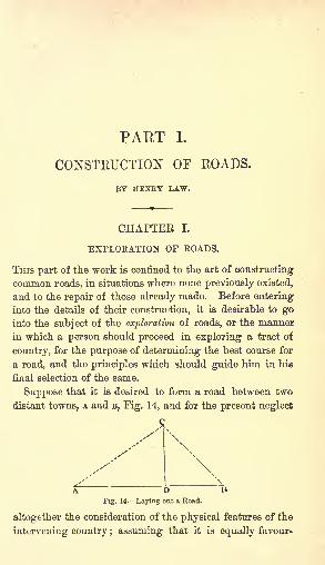
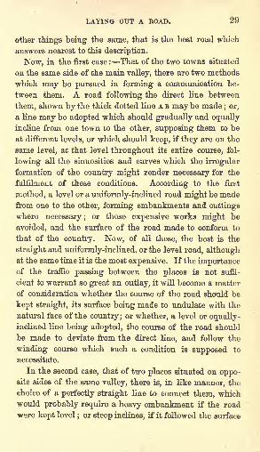
Suppose that it is desired to form a road between two
distant towns, A and B, Fig. 14, and for the present neglect
c
DFig. 14. Laying out a Road.
altogether the consideration of the physical features of the
intervening country ; assuming that it is equally favour-
22 EXPLORATION OF ROADS.
able, whatever line is selected. Now, at first sight, it
would appear that, under such circumstances, a perfectly
straight line drawn from, one town to the other, would be
the best that could be chosen. But on a more careful
examination of the locality, it may be found that there is
a third town, c, situated somewhat on one side of the
straight line drawn from A to B; and, although the
primary object is to connect the two latter, it may, never-
theless, be considerably better if the whole of the three
towns were put into mutual connection with each other.
Now this may be effected in three different ways ; any one
of which might, under certain circumstances, be the best.
In the first place, a straight road might, as originally sug-
gested, be formed from A to B, and, in a similar manner,
two other straight roads from A to c, and from B to c. This
would be the most perfect way of effecting the object in
view, the distance between any two of the towns beingreduced to the least possible length. It would, however,
be attended with considerable expense, and it would be
requisite to construct a much greater length of road than
according to the second plan, which would be to form, as
before, a straight road from A to B, and from c to construct
a road which should join the former at a point D, so as to
be perpendicular to it;the traffic between A or B and o,
would proceed to the point D, and then turn off to c. Bythis arrangement, while the length of the roads would be
very materially decreased, only a slight increase would be
occasioned in the distance between c and the other two
towns. The third method would be to form only the two
roads A c and c B. In this case, the distance between A and
B would be somewhat increased, while that between A and
c, or B and c, would be diminished;the total length of
road to be constructed would also be lessened.
As a general rule, it may be taken that the last of these
methods is the best, and most convenient for the public ;
LAYING OUT A ROAD. 23
that is to say, if the pnysical character of the country
does not determine the course of the road, it will generally
be found best not to adopt a perfectly straight line, but to
vary the line so as to pass through the principal towns
near its general course. The public may thus be con-
veyed from town to town with greater facility and less
expense than if the straight line were adopted, and the
towns were to communicate with it by means of branch
roads. On the first system, vehicles established to convey
passengers or goods between the two terminal towns,
would pass through all those which were intermediate;
whilst, if the straight line and branch-road system were
adopted, a system of branch coaches would be required
for meeting the coaches on the main line.
In laying out a road in an old country, in which the
position of the several towns, or other centres of industry,
requiring road accommodation, is already determined,
there is less liberty for the selection of the line of road
than in a new country, where the only object is to establish
the easiest and best road between two distant stations. In
the first case, the positions of the towns, and other in-
habited districts situated near the intended road, are to be
taken into consideration, and the course of the road may,to a certain extent, be controlled thereby ; whilst, in the
second case, the physical character of the country would
alone be investigated, and it alone would constitute the
basis for the selection of a new route.
Whichever of these two cases may be dealt with, in the
selection and adoption of the line of road between two
points, a careful examination of the physical character of
the country should be made, and the line of the route
determined in accordance with physical conditions.
One of the first points which attract notice in making an
examination of an ordinary tract of country, is the uneven-
ness or undulation of its surface;but if the observation be
24 EXPLORATION OF ROADS.
extended a little further, one general principle of con-
formation is perceived even in the most irregular countries.
The country is intersected in various directions by rivers,
increasing in size as they approach their point of dis-
charge ;towards these main rivers, lesser rivers approach
on both sides, running right and left through the country ;
and into these, again, enter still smaller streams and
brooks. Furthermore, the ground falls in every direction
towards the natural watercourses, forming ridges, more
or less elevated, running between them, and separating
from each other the districts drained by the streams.
It is the first business of a person, engaged in laying
out a line of road, to make himself thoroughly acquainted
with the features of the country ;he should possess him-
self of a plan or map, showing accurately the course of all
the rivers and principal watercourses, and upon this he
should further mark the lines of greatest elevation, or the
ridges separating the several valleys through which they
flow. It is also of peculiar service when the plan contains
contour lines showing the comparative levels of any two
points, and the rates of declivity of every portion of the
country's surface. The system of showing upon plans the
levels of the ground by means of contour-lines, is one of
much utility, not only in the selection of roads and other
lines of communication, but also for settling the lines of
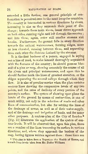
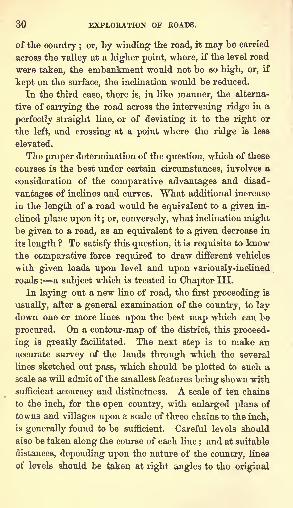
the drainage of towns, as well as of their water-supply,and of the drainage and irrigation of lands, and for manyother purposes. A contour-plan of the City of London *
(Fig. 15) illustrates the application of the system of con-
tour levels. It will be observed that, upon this plan, there
are a number of fine lines traversing its surface in various
directions, and, where they approach the borders of the
map, having figures written against them : these lines are
* This plan is taken from a Beport on the Health of Towns, andis madu from levels 'aken from Mr. Butler Williams.
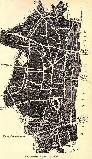
Valley of the Fleet Ditch.
Fig. 15.-Contour Plan of London.
26 EXPLORATION OF ROADS.
termed contour-lines, and they denote that the level of the
ground is identical throughout the whole of their course :
that is to eay, that every part of the ground over which the
line passes, is at a certain height above a known fixed
point, the height being indicated by the figures written
against the line. At the point A, for example, in Smithfield
Market, a line with the figures 57 is attached, which indi-
cates that the ground at that spot is 57 feet above some
point to which all the levels are referred. If the course of
the line be traced, it is found that it cuts Newgate Street
at the point B, passes thence to the bottom of Paternoster
Eow at the point i, through St. Paul's Churchyard at c, to
Cheapside at D. It then curves round towards the point
from which it first started, and crosses Aldersgate Street
twice, at E and F; and, after intersecting Fore Street,
Cripplegate, in the point a, it again meets the boundaryof the City at H. It is thus shown that, tracing the
course of this line, each of those points stands at the same
height, namely, 57 feet above a certain fixed point, termed
the datum. This point is, in the present instance, 10 feet
below the top of the cap-stone at the foot of the step, on the
east side of old Blackfriars Bridge. Each interval between
the lines in Fig. 8, indicates a difference of level of 18
inches;and by counting the number of these lines which
intersect a street or road within any given distance, the
rise or fall in the street is at once ascertained by simple
multiplication. Thus, looking at the line of Bishopsgate
Street, near the north end, the contour-line 45 is seen, in-
dicating that that point in the street is 45 feet above the
datum, and nine lines are found intersecting the street
between that point and the top of Cornhill. It is calcu-
lated, therefore, that this point is (1-5 X 9 =) 13-5 feet
above the other end of the street, or 58-5 feet above the
datum. The rate of inclination of the ground may also be
estimated by the relative proximity or distance apart of
LAYING OUT A ROAD. 27
these lines. Thus, on the northern side of the City, where
the ground is comparatively level, the lines are far apart ;
whereas, on the side next the Thames, and again on each
side of the line of Farringdon Street, which marks the
course of the valley of the old river Meet, where the sur-
face is very hilly, the contour lines lie close together.
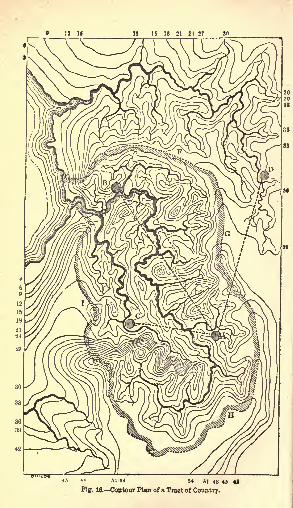
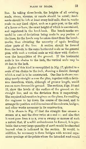
The plan, Fig. 16, shows an imaginary tract of country,
to illustrate more clearly the mode of showing by means
of contour-lines, the physical features of a country. The
hatched line, E F G H i, is supposed to be an elevated ridge,
encircling the valley shown in the plan ;the fine black
lines are contour-lines, indicating that the ground over
which they pass is at the altitude above some knownmark expressed by the figures written against them in the
margin. It will be observed that these lines, by their
greater or less distance, have the effect of shading, and
make apparent to the eye, the undulations and irregu-
larities in the surface of the country.
In laying out a line of road, there are three cases which
may have to be treated, and each of these is exemplified in
the plan, Fig. 16. First, the two places to be connected, as
the towns A and B on the plan, may be both situated in the
same valley, and upon the same side of it;that is, that
they are not separated from each other by the main stream
which drains the valley. This is the simplest case. Secondly,
although both in the same valley, the two places may be
on the opposite sides of the valley, as at A and c, being
separated by the maia river. Thirdly, they may be situ-
ated in different valleys, separated by an intervening ridgeof ground more or less elevated, as at A and D. In layingout an extensive line of road, it frequently happens that all
these cases have to be dealt with : frequently, perhaps,
during its course.
The most perfect road is that of which the course is
perfectly straight, and the surface perfectly level; and, all
c 2
IS 15 18 21 4 27
54 51 48 49 41
tO. Contour Plan of a Tract of Country.
LAYING OUT A ROAD. 29
other things being the same, that is the best road which
answers nearest to this description.
Now, in the first case : That of the two towns situated
on the same side of the main valley, there are two methods
which may be pursued in forming a communication be-
tween them. A road following the direct line between
them, shown by the thick dotted line A B may be made; or,
a line may be adopted which should gradually and equally
incline from one town to the other, supposing them to be
at different levels, or which should keep, if they are on the
same level, at that level throughout its entire course, fol-
lowing all the sinuosities and curves which the irregular
formation of the country might render necessary for the
fulfilment of these conditions. According to the first
method, a level or a uniformly-inclined road might be madefrom one to the other, forming embankments and cuttings
where necessary ;or these expensive works might be
avoided, and the surface of the road made to conform to
that of the country. Now, of all these, the best is the
straight and uniformly-inclined, or the level road, althoughat the same time it is the most expensive. If the importanceof the traffic passing between the places is not suffi-
cient to warrant so great an outlay, it will become a matter
of consideration whether the course of the road should be
kept straight, its surface being made to undulate with the
natural face of the country ;or whether, a level or equally-
inclined line being adopted, the course of the road should
be made to deviate from the direct line, and follow the
winding course which such a condition is supposed to
necessitate.
In the second case, that of two places situated on oppo-site sides of the same valley, there is, in like manner, the
choice of a perfectly straight line to connect them, which
would probably require a heavy embankment if the road
were kept level;or steep inclines, if it followed the surface
30 EXPLORATION OF ROADS.
of the country ; or, "by winding the road, it may be carried
across the valley at a higher point, where, if the level road
were taken, the embankment would not be so high, or, if
kept on the surface, the inclination would be reduced.
In the third case, there is, in like manner, the alterna-
tive of carrying the road across the intervening ridge in a
perfectly straight line, or of deviating it to the right or
the left, and crossing at a point where the ridge is less
elevated.
The proper determination of the question, which of these
courses is the best under certain circumstances, involves a
consideration of the comparative advantages and disad-
vantages of inclines and curves. What additional increase
in the length of a road would be equivalent to a given in-
clined plane upon it; or, conversely, what inclination mightbe given to a road, as an equivalent to a given decrease in
its length ? To satisfy this question, it is requisite to knowthe comparative force required to draw different vehicles
with given loads upon level and upon variously-inclined
roads : a subject which is treated in Chapter III.
In laying out a new line of road, the first proceeding is
usually, after a general examination of the country, to lay
down one or more lines upon the best map which can be
procured. On a contour-map of the district, this proceed-
ing is greatly facilitated. The next step is to make an
accurate survey of the lands through which the several
lines sketched out pass, which should be plotted to such a
scale as will admit of the smallest features being shown with
sufficient accuracy and distinctness. A scale of ten chains
to the inch, for the open country, with enlarged plans of
towns and villages upon a scale of three chains to the inch,
is generally found to be sufficient. Careful levels should
also be taken along the course of each line;and at suitable
distances, depending upon the nature of the country, lines
of levels should be taken at right angles to the original
PLANS OF ROADS. 31
line. In taking these levels, the heights of all existing
roads, rivers, streams, or canals should be noted; bench-
marks should be left at least every half-mile, that is, marks
made on any fixed object, such as a gate-post, or the side
of a house or barn, the exact height of which is ascertained,
and registered in the level-book. The bench-marks are
useful in case of deviations being made in any portion of
the lines, for the levels may be taken direct from the bench-
marks, thus obviating the necessity of again levelling
other parts of the line. A section should be formed
from the levels, to the same horizontal scale as the general
plan, with such a vertical scale as will show with distinct-
ness the inequalities of the ground. If the horizontal
scale is ten chains to the inch, the vertical scale may be
20 feet to the inch.
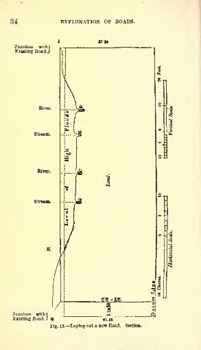
A plan of this kind is exemplified in Fig. 17, plotted to a
scale of ten chains to the inch, showing a district through
which a road is to be constructed. One line is shown run-
ning nearly straight across the plan, together with a devia-
tion therefrom, which, although of greater length, would
run on more favourable ground. The sections, Figs. 18 and
19, show the levels of the surface of the ground on the
straight line, and on the deviation from it respectively.
The required information is given on the plans, for enabling
the engineer to lay down the course of the road, and to
arrange the position and dimensions of the culverts, bridges,
and other works necessary in its construction.
It is shown in Fig. 17 that the straight line crosses a
stream at B, and the river twice at o and D;and also that
it must pass from B to E, over a swamp or morass of such
a nature that, if a solid embankment be formed, it is pro-
bable that a very large quantity of earth would be absorbed
beyond what is indicated in the section. It would, in
addition, be necessary to form bridges with several capa-
cious openings at the points where the intended road would
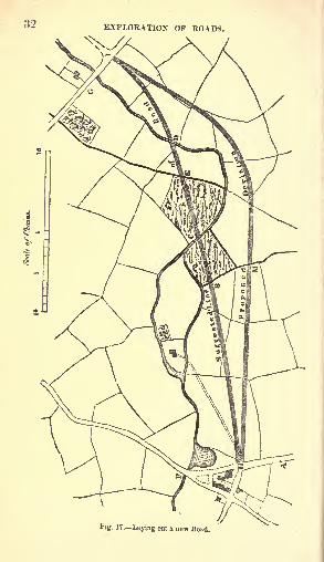
EXPLORATION OF ROADS.
fig. 17. Laying out a new Bead.
SECTIONS OF ROADS. S3
cross the river, since the river would be liable to be flooded.
Suchdisadvantages attending the more obvious route, would
induce the engineer to sketch out some other line, by which
they would be avoided. He would have the levels taken,
with other needful information, to enable him to choose
between the two routes.
The manner in which the sections should be drawn, and
the nature of the information to be given upon them, are
exemplified in Figs. 18 and 19. In addition, data of the fol-
lowing character should be obtained, and should be entered
either in the survey field-book, or in the level-book.
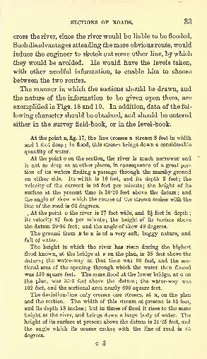
At the point B, fig. 17, the line crosses a stream 8 feet in width
and 1 foot deep ;in flood, this stream brings down a considerable
quantity of water.
At the point c on the section, the river is much narrower and
is not so deep as at other places, in consequence of a great por-tion of its waters finding a passage through the marshy groundon either side. Its width is 16 feet, and its depth 2 feet; the
velocity of the current is 95 feet per minute ; the height of its
surface at the present time is 30*10 feet above the datum; andthe angle of skew which the course of the stream makes with the
line of the road is 62 degrees.
,At the point D the river is 27 feet wide, and 2| feet in depth ;
its velocity 87 feet per minute ; the height of its surface above
the datum 29-96 feet;and the angle of skew 49 degrees.
The ground from B to E is of a very soft, boggy nature, and
full of water.
The height to which the river has risen during the highestflood known, at the bridge at F on the plan, is 35 feet above the
datum; the water-way at that time was 90 feet, and the sec-
tional area of the opening through which the water then flowed
was 550 square feet. The same flood at the lower bridge, at G on
the plan, was 35-3 feet above the datum; the water-way was102 feet, and the sectional area nearly 600 square feet.
The deviation-line only crosses one stream, at M, on the planand the section. The width of this stream at present is 15 feet,
and its depth 18 inches;but in times of flood it rises to the same
height as the river, and brings down a large body of water. The
height of its surface at present above the datum is 31-25 feet, and
the angle which its course makes with the line of road is 85
degrees.
EXPLORATION OF ROADS.
Junction with")
Existing RoadJ
Eye.
Stream.
Junction with>Existing RoadJ
2S-n
41-S
Fig. 18 Laying otit a new Road. Section.
SECTIONS OF ROAPS.
fTU
Existing Road.
37-25
41 25
19. Laying out a new Road. Section,
36 EXPLORATION OF ROADS.
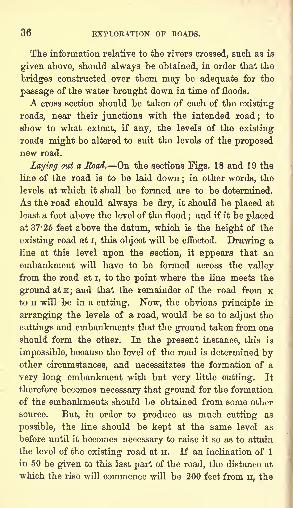
The information relative to the rivers crossed, such as is
given above, should always be obtained, in order that the
bridges constructed over them may be adequate for the
passage of the water brought down in time of floods.
A cross section should be taken of each of the existing
roads, near their junctions with the intended road;
to
show to what extent, if any, the levels of the existing
roads might be altered to suit the levels of the proposednew road.
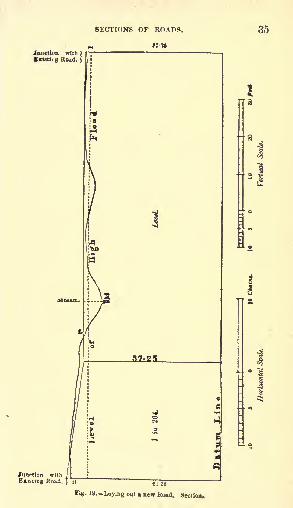
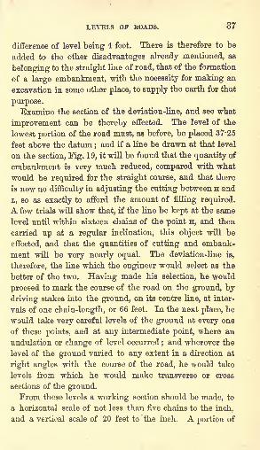
Laying out a Road. On the sections Figs. 18 and 19 the
line of the road is to be laid down;in other words, the
levels at which it shall be formed are to be determined.
As the road should always be dry, it should be placed at
least a foot above the level of the flood;and if it be placed
at 37-25 feet above the datum, which is the height of the
existing road at i, this object will be effected. Drawing a
line at this level upon the section, it appears that an
embankment will have to be formed across the valley
from the road at i, to the point where the line meets the
ground at K; and that the remainder of the road from Kto H will be in a cutting. Now, the obvious principle in
arranging the levels of a road, would be so to adjust the
cuttings and embankments that the ground taken from one
should form the other. In the present instance, this is
impossible, because the level of the road is determined byother circumstances, and necessitates the formation of a
very long embankment with but very little cutting. It
therefore becomes necessary that ground for the formation
of the embankments should be obtained from some other
source. But, in order to produce as much cutting as
possible, the line should be kept at the same level as
before until it becomes necessary to raise it so as to attain
the level of the existing road at H. If an inclination of 1
in 50 be given to this last part of the road, the distance at
which the rise will commence will be 200 feet from H, the
LEA-ELS OF ROADS. 37
difference of level being 4 feet. There is therefore to be
added to the other disadvantages already mentioned, as
belonging to the straight line of road, that of the formation
of a large embankment, with the necessity for making an
excavation in some other place, to supply the earth for that
purpose.
Examine the section of the deviation-line, and see what
improvement can be thereby effected. The level of the
lowest portion of the road must, as before, be placed 37-25
feet above the datum;and if a line be drawn at that level
on the section, Fig. 19, it will be found that the quantity of
embankment is very much reduced, compared with what
would be required for the straight course, and that there
is now no difficulty in adjusting the cutting between H and
L, so as exactly to afford the amount of filling required.
A few trials will show that, if the line be kept at the same
level until within sixteen chains of the point H, and then
carried up at a regular inclination, this object will be
effected, and that the quantities of cutting and embank-
ment will be very nearly equal. The deviation-line is,
therefore, the line which the engineer would select as the
better of the two. Having made his selection, he would
proceed to mark the course of the road on the ground, by
driving stakes into the ground, on its centre line, at inter-
vals of one chain-length, or 66 feet. In the next place, he
would take very careful levels of the ground at every one
of these points, and at any intermediate point, where an
undulation or change of level occurred;and wherever the
level of the ground varied to any extent in a direction at
right angles with the course of the road, he would take
levels from which he would make transverse or cross
sections of the ground.From these levels a working section should be made, to
a horizontal scale of not less than five chains to the inch,
and a vertical scale of 20 feet to the inch. A portion of
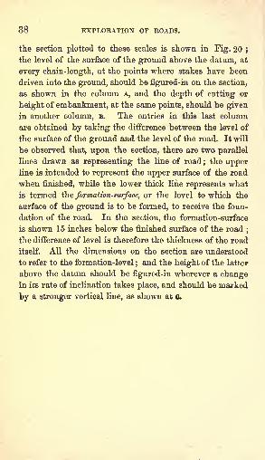
38 EXPLORATION OF ROADS.
the section plotted to these scales is shown in Fig. 20 ;
the level of the surface of the ground above the datum, at
every chain-length, at the points where stakes have been
driven into the ground, should be figured-in on the section,
as shown in the column A, and the depth of cutting or
height of embankment, at the same points, should be given
in another column, B. The entries in this last column
are obtained by taking the difference between the level of
the surface of the ground and the level of the road. It will
be observed that, upon the section, there are two parallel
lines drawn as representing the line of road;the upper
line is intended to represent the upper surface of the road
when finished, while the lower thick line represents what
is termed the formation-surface, or the level to which the
surface of the ground is to be formed, to receive the foun-
dation of the road. In the section, the formation-surface
is shown IS inches below the finished surface of the road;
the difference of level is therefore the thickness of the road
itself. All the dimensions on the section are understood
to refer to the formation-level;and the height of the latter
above the datum should be figured-in wherever a changein its rate of inclination takes place, and should be marked
by a stronger vertical line, as shown at a
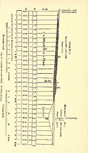
/ Jurist 'on with\ Existing Head.
s -
CHAPTER n.
CONSTRUCTION OF ROADS: EARTHWORK ANDDRAINAGE.
Earthwork. This term is applied to whatever relates to
the construction of the excavations and the embankments,
to prepare them for receiving the road-covering.
When the cuttings are of considerable depth, trial pits
should be sunk at intervals of about ten chains, to the
depth of the intended cutting, for the purpose of ascertain-
ing the nature of the ground, and determining the slopes
at which the sides of the cutting would safely stand, as
well as the slope at which the same earth would stand
when formed into the embankments. The cuttings and
embankments should be numbered on the section, and the
slopes intended to be given to each should be stated uponthe "section. The contents of a cutting or an embankment,that is, the number of cubic yards which will have to be
moved for its formation, with the intended slope, should
then be calculated and stated upon the section. The man-ner of calculating these quantities will be explained in a
subsequent chapter.
Wherever rivers or streams are crossed, bridges or cul-
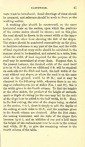
EARTHWORK. 41
verts must be introduced;detail drawings of these should
be prepared, and reference should be made to them on the
working section.
A working plan should be constructed, on the same
horizontal scale as the section, upon which the positions
of the centre stakes should be shown;and on this plan
the road should be drawn to its correct width at the upper
surface, with other lines showing the feet of the slopes.
The stakes should be numbered consecutively on the plan,
to facilitate reference to any part of the line, and the width
of land required at every stake should be calculated in the
manner about to be described, and entered in a table, from
which the width of land required for the purpose of the
road may be ascertained at every chain. Suppose that, in
the present instance, the finished width of the road itself
is to be 40 ft., and that an additional 6 ft. will be requiredon each side for the ditch and bank, the half width of the
road without any slopes, or where the road is on the same
level as the ground, would be 26 ft.;and it may be
observed in the following table, wherever there is no cut-
ting or embankments (as at stakes Nos. 1 and 30), this is
the width given in the fourth column. To find the heightsat the other stakes, the product of the height of embank-
ment or depth of cutting (as the case may be) by the ratio
of the slope is to be added to the half width, 26 ft. Thus,in the first cutting, the ratio of the slopes being, as stated
on the section, 1 to 1, there is simply to add the depths of
the cutting at each stake to 26 ft., and the numbers givenin the fourth column are obtained. After the 21st stake,
the cutting terminates, and the ratio of the slopes then
becomes 1$ to 1, and an addition of one and a half times
the height of the embankment is to be made to the normal
half width, 26 ft., to give the remaining values in the
fourth column of the table.
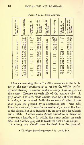
42 EARTHWORK AND DRAINAGE.
TABLE No. 2. SIDE WIDTHS.
EARTHWORK. 43
upon the centre line, wherever a change in the inclination
of the road takes place (as at the 17th stake in the present
instance), upon which a cross piece should be placed at the
intended height of the formation-surface of the road, and
intermediate heights should be put up at such distances as
will enable the workmen to keep the embankments to their
proper level. For cuttings, pits must be sunk correspond-
ingly, at certain intervals, to the depth of the formation-
surface, to serve as guides to the excavators in formingthe cutting.
In the foregoing example, the slopes have been taken
at ratios of 1 to 1, and H to 1;but it should be remem-
bered that the inclination of the side slopes demands
peculiar attention. The proper inclination depends on the
nature of the soil, and the action of the atmosphere and
of internal moisture upon it. "In common soils, as or-
dinary garden-earth formed of a mixture of clay and
sand, compact clay, and compact stony soils, althoughthe side slopes would withstand very well the effects of
the weather with a steeper inclination, it is best to givethem two base to one perpendicular ;
as the surface of
the roadway will, by this arrangement, be well exposedto the action of the sun and air, which will cause a
rapid evaporation of the moisture on the surface. Pure
sand and gravel may require a greater slope, accordingto circumstances. In all cases where the depth of the
excavation is great, the base of the slope should be in-
creased. It is not usual to use any artificial means to
protect the surface of the side slopes from the action of
the weather ; but it is a precaution which, in the end, will
save much labour and expense in keeping the roadway in
good order. The simplest means which can be used for
this purpose, consist in covering the slopes with good sods,
or else with a layer of vegetable mould about 4 inches
thick, carefully laid and sown with grass seed. These
44 EARTHWORK AND DRAINAGE.
means are amply sufficient to protect the side slopes from
injury when they are not exposed to any other causes of
deterioration than the wash of the rain, and the action of
frost on the ordinary moisture retained by the soiL
"The side slopes form usually an unbroken surface from
the foot to the top. But in deep excavations, and particu-
larly in soils liable to slips, they are sometimes formed
with horizontal offsets, termed tenches, which are made a
few feet wide, and have a ditch on the inner side to receive
the surface-water from the portion of the side slope above
them. These benches catch and retain the earth that mayfall from the portion of the side slope above.
"When the side slopes are not protected, it will be well,
in localities where stone is plenty, to raise a small wall of
dry stone at the foot of the slopes, to prevent the wash of
the slopes from being carried into the roadway."A covering of brush-wood, or a thatch of straw, mayalso be used with good effect
; but, from their perish-
able nature, they will require frequent renewal and
repairs.' ' In excavations through solid rock, which does not
disintegrate on exposure to the atmosphere, the sides
might be made perpendicular ; but as this would exclude,
in a great degree, the action of the sun and air, which is
essential to keeping the road-surface dry and in good order,
it is necessary to make the side slopes with an inclination,
varying from one base to one perpendicular, to one base
to two perpendicular, or even greater, according to the
locality : the inclination of the slope on the south side in
northern latitudes being the greater, to expose better the
road-surface to the sun's rays.
"The slaty rocks generally decompose rapidly on the sur-
face, when exposed to moisture and the action of frost.
The side slopes in rocks of this character may be cut into
steps, and then be covered by a layer of vegetable mould
EXCAVATION IN ROCK. 45
sown in grass seed, or else the earth may be sodded in the
usual way."The stratified soils and rocks, in which the strata have
a dip, or inclination to the horizon, are liable to slips, or
to give way, by one stratum becoming detached and sliding
on another;which is caused either from the action of frost,
or from the pressure of water, which insinuates itself
between the strata. The worst soils of this character are
those formed of alternate strata of clay and sand; particu-
larly if the clay is of a nature to become semi-fluid whenmixed with water. The best preventives that can be re-
sorted to in these cases are, to adopt a system of thorough
drainage, to prevent the surface-water of the ground from
running down the side slopes, and to cut off all springs
which run towards the roadway from the side slopes. The
surface-water may be cut off by means of a single ditch
made on the up-hill side of the road, to catch the water
before it reaches the slope of the excavation, and conveyit off to the most convenient natural water-courses
; for, in
almost every case, it will be found that the side slope on
the down-hill side is, comparatively speaking, but slightly
affected by the surface-water.
"Where slips occur from the action of springs, it fre-
quently become a very difficult task to secure the side
slopes. If the sources can be easily reached by excavatinginto the side slopes, drains formed of layers of fascines, or
brush-wood, may be placed to give an outlet to the water,
and prevent its action upon the side slopes. The fascines
may be covered on top with good sods laid with the grassside beneath, and the excavation made to place the drain
be filled in with good earth well rammed. Drains formed
of broken stone, covered in like manner on top with a
layer of sod to prevent the drain from becoming choked
with earth, may be used under the same circumstances as
fascine drains. Where the sources are not isolated, and
46 EARTHWORK AND DRAINAGE.
the whole mass of the soil forming the side slopes appears
saturated, the drainage may be effected by excavatingtrenches a few feet wide at intervals to the depth of some
feet into the side slopes, and filling them with broken
stone, or else a general drain of broken stone may be made
throughout the whole extent of the side slope by excava-
ting into it. When this is deemed necessary, it will be
well to arrange the drain like an inclined retaining-wall,
with buttresses at intervals projecting into the earth
further than the general mass of the drain. The front
face of the drain should, in this case, also be covered with
a layer of sods with the grass side beneath, and upon this
a layer of good earth should be compactly laid to form the
face of the side slopes. The drain need only be carried
high enough above the foot of the side slope to tap all the
sources;and it should be sunk sufficiently below the road-
way surface to give it a secure footing.
"The drainage has been effected, in some cases, by sink-
ing wells or shafts at some distance behind the side slopes,
from the top surface to the level of the bottom of the ex-
cavation, and leading the water which collects in them, by
pipes, into drains at the foot of the side slopes. In others,
a narrow trench has been excavated, parallel to the axis of
the road, from the top surface to a sufficient depth to tapall the sources which flow towards the side slope, and a
drain formed either by filling the trench wholly with
broken stone, or else by arranging an open conduit at the
bottom to receive the water collected, over which a layer
of brush-wood is laid, the remainder of the trench beingfilled with broken stone."*
In some instances, the side slopes of very bad soils
have been secured by a facing of brick arranged in a
manner very similar to the method resorted to for securing
the perpendicular sides of narrow deep trenches by a
timber-facing. The plan pursued is, to place, at intervals
* "A Treatise on Civil Engineering," by D. H. Mahan, 2nd edition,
page 411.
EMBANKMENTS. 47
along the excavation, strong buttresses of brick on each
side, opposite to each other, and to connect them at bottom
by a reversed arch. Between these buttresses are placed,
at suitable heights, one or more brick beams, formed at
bottom with a flat segment arch, and at top with a like
arch inverted. The buttresses, secured in this way, serve
as piers for vertical cylindrical arches, which form the
facing and support the pressure of the earth between the
buttresses." In forming the embankments the side slopes should be
made with a greater inclination than that which the earth
naturally assumes;for the purpose of giving them greater
durability, and to prevent the width of the top surface,
along which the roadway is made, from diminishing by
every change in the side slopes, as it would were they
made with the natural slope. To protect the side slopes
more effectually, they should be sodded, or sown in
grass seed; and the surface-water of the top should
not be allowed to run down them, as it would soon
wash them into gullies, and destroy the embankment.
In localities where stone is plentiful, a sustaining wall of
dry stone may be advantageously substituted for the side
slopes.
"To prevent, as far as possible, the settling which takes
place in embankments, they should be formed with great
care;the earth being laid in successive layers of about
four feet in thickness, and each layer well settled with
rammers. As this method is very expensive, it is seldom
resorted to except in works which require great care, and
are of trifling extent. For extensive works, the method
usually followed, on account of economy, is to embank out
from one end, carrying forward the work on a level with
the top surface. In this case, as there must be a want of
compactness in the mass, it would be best to form the
outsides of the embankment first, and to gradually fill in
48 EARTHWORK AND DRAINAGE.
towards the centre, in order that the earth may arrange
itself in layers with a dip from the sides inwards;
this will in a great measure counteract any tendency to
slips outward. The foot of the slopes should be secured
by buttressing them either by a low stone wall, or by
forming a slight excavation for the same purpose."*"In some cases surface drains, termed catch-water drains,
are made on the side slopes of cuttings. They are run up
obliquely along the surface, and empty directly into the
cross drains which convey the water into the natural water-
courses.
"When the roadway is in side-forming, cross drains of
the ordinary form of culverts are made, to convey the
water from the side channels and the covered drains into
the natural water-courses. They should be of sufficient
dimensions to convey off a large volume of water, and to
admit a man to pass through them, so that they may be
readily cleared out, or even repaired, without breaking upthe roadway over them.
"The only drains required for embankments are the ordi-
nary side channels of the roadway, with occasional culverts
to convey the water from them into the natural water-
courses. Great care should be taken to prevent the sur-
face-water from running down the side slopes, as theywould soon be washed into gullies by it.
"When the axis of the roadway is laid out on the side
slope of a hill, and the road-surface is formed partly by
excavating and partly by embanking out, the usual and
most simple method is to extend out the embankment
gradually along the whole line of excavation. This method
is insecure, and no pains therefore should be spared to give
the embankment a good footing on the natural surface
upon which it rests, particularly at the foot of the slope.
For this purpose the natural surface should be cut into
steps, or offsets, and the foot of the slope be secured by* "A Treatise on Civil Engineering," by P. H. Mahan, 2nd edition,
page 414.
ROADS IN SIDE-FORMING. 49
buttressing it against a low stone wall, or a small terrace
of carefully rammed earth.
"In side-formings along a natural surface of great incli-
nation, the method of construction just explained will not
be sufficiently secure; sustaining-walls must be substituted
for the side slopes, both of the excavations and embank-
ments. These walls may be made simply of dry stone,
when the stone can be procured in blocks of sufficient size
to render this kind of construction of sufficient stability to
resist the pressure of the earth. But when the blocks of
stone do not offer this security, they must be laid in mortar,
and hydraulic mortar is the only kind which will form a
safe construction. The wall which supplies the slope of
the excavation should be carried up as high as the natural
surface of the ground ;the one that .sustains the embank-
ment should be built up to the surface of the roadway ;and
a parapet-wall should be raised upon it, to secure vehicles
from accidents in deviating from the line of the roadway.'A road may be constructed partly in excavation and
partly in embankment along a rocky ledge, by blasting the
rock, when the inclination of the natural surface is not
greater than one perpendicular to two base;but with
a greater inclination than this, the whole should be in
excavation.
"There are examples of road constructions, in localities
like the last, supported on a frame-work, consisting of
horizontal pieces, which are firmly fixed at one end by
being let into holes drilled in the rock, and are sustained
at the other by an inclined strut underneath, which rests
against the rock in a shoulder formed to receive it.
"When the excavations do not furnish sufficient earth for
the embankments, it is obtained from excavations termed
side-cuttings, made at some place in the vicinity of the
embankment, from which the earth can be obtained with
the most economy.
50 EARTHWORK AND DRAINAGE.
"If the excavations furnish more earth than is required
for the embankment, it is deposited in what is termed a
spoil-lank, on the side of the excavation. The spoil-bank
should be made at some distance back from the side slope
of the excavation, and on the down-hill side of the top-
surface;and suitable drains should be arranged to carry
off any water that might collect near it and affect the side
slope of the excavation.
The forms to be given to side-cuttings and spoil-banks
will depend, in a great degree, upon the locality; they
should, as far as practicable, be such that the cost of
removal of the earth shall bd the least possible."*
* "A Treatise on Civil Engineering," by D. H. Mahan, 2nd edition,
page 415.
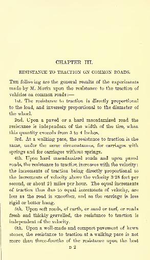
CHAPTEE HI.
RESISTANCE TO TRACTION ON COMMON ROADS.
THE following are the general results of the experimentsmade by M. Morin upon the resistance to the traction of
vehicles on common roads :
1st. The resistance to traction is directly proportional
to the load, and inversely proportional to the diameter of
the wheel.
2nd. Upon a paved or a hard macadamized road the
resistance is independent of the width of the tire, whenthis quantity exceeds from 3 to 4 inches.
3rd. At a walking pace, the resistance to traction is the
same, under the same circumstances, for carriages with
springs and for carriages without springs.
4th. Upon hard macadamized roads and upon paved
roads, the resistance to traction increases with the velocity :
the increments of traction being directly proportional to
the increments of velocity above the velocity 3-28 feet per
second, or about 2J miles per hour. The equal increments
of traction thus due to equal increments of velocity, are
less as the road is smoother, and as the carriage is less
rigid or better hung.5th. Upon soft roads, of earth, or sand or turf, or roads
fresh and thickly gravelled, the resistance to traction is
independent of the velocity.
6th. Upon a well-made and compact pavement of hewn
stones, the resistance to traction at a walking pace is not
more than three-fourths of the resistance upon the best
D 2
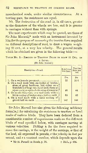
52 RESISTANCE TO TRACTION ON COMMON ROADS.
macadamized roads, under similar circumstances. At a
trotting pace, the resistances are equal.
7th. The destruction of the road is, in all cases, greater
as the diameters of the wheels are less, and it is greater
in carriages without than with springs.
The next experiments which may be quoted, are those of
Sir John Macneil,* made with an instrument invented byhim for the purpose of measuring the tractive force required
on different descriptions of road, to draw a wagon weigh-
ing 21 cwt., at a very low velocity. The general results
which he obtained are given in the following table :
TABLE No. 3. RESULTS OF TRACTION FORCE TO DRAW 21 CWT. ONA LEVEL.
(Sir John Macneil.)
Description of road.
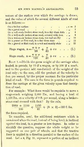
SIR JOHN MACNEIL'S EXPERIMENTS. 53
nature of the surface over which the carriage is drawn,
and the value of which for several different kinds of road
is as follows :
On a timber surface ....On a paved road .....On a well-made broken stone road, in a dry clean state
On a well-made broken stone road, covered with dust
On a well-made broken stone road, wet and muddyOn a gra-vel or flint road, in a dry clean state
On a gravel or flint road, in a wet and muddy state
Stage wagon, B=^J" + ^ + (!)
Stagecoach, B =^-w + fQ + (2.)
EULE 1. Divide the gross weight of the carriage when
loaded, in pounds, by 93 if a wagon, or by 100 if a coach,
and to the quotient add one-fortieth of the weight of the
load only ;to the sum, add the product of the velocity in
feet per second, by the proper constant for the particular
kind of road. The sum is the force in pounds required to
draw the carriage at the given velocity upon that descrip-
tion of road.
For example : What force would be requisite to move a
stage-coach weighing 2,060 Ibs., and having a load of
1,100 Ibs., at a velocity of 9 ft. per second, along a broken-
stone road covered with dust ? By the rule,
2060^1100 + noo + (8 x 9H131 .X ,bs
the force required.
To consider, next, the additional resistance which is
occasioned when the road, instead of being level, is inclined
against the load, in a greater or less degree. In order to
simplify the question, suppose the whole weight to be
supported on one pair of wheels, and that the tractive
force is applied in a direction parallel to the surface of the
road. Let A B, Fig. 21, represent a portion of an inclined
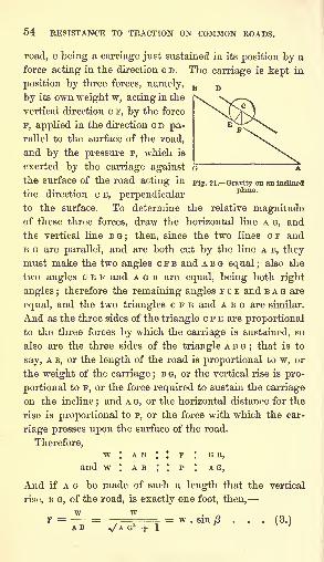
54 RESISTANCE TO TRACTION ON COMMON ROADS.
road, c being a carriage just sustained in its position by a
force acting in the direction c D. The carriage is kept in
position by three forces, namely,
by its own weight w, acting in the
vertical direction c F, by the force
F, applied in the direction c D pa-rallel to the surface of the road,
and by the pressure P, which is
exerted by the carriage against G~
the surface of the road acting in pig. 21.-Gravity on an inclined
the direction c E, perpendicularto the surface. To determine the relative magnitudeof these three forces, draw the horizontal line A G, and
the vertical line B G; then, since the two lines c F and
B G are parallel, and are both cut by the line A B, theymust make the two angles c F B and A B G equal ;
also the
two angles c E F and A o B are equal, being both right
angles ;therefore the remaining angles F c E and BAG are
equal, and the two triangles c F E and A B G are similar.
And as the three sides of the triangle c F E are proportional
to the three forces by which the carriage is sustained, so
also are the three sides of the triangle A B G;that is to
say, A B, or the length of the road is proportional to w, or
the weight of the carriage ;B G, or the vertical rise is pro-
portional to F, or the force required to sustain the carriage
on the incline;and A G, or the horizontal distance for the
rise is proportional to P, or the force with which the car-
riage presses upon the surface of the road.
Therefore,W * A B I I F I G B,
and w : A B : : P : A G,
And if A G be made of such a length that the vertical
rise, B G, of the road, is exactly one foot, then,
F = = = w . sin B . . . (3.)AB v/AG- + 1V ;
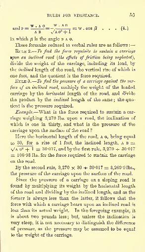
RULES FOR RESISTANCE.
. ', ,= w . cos /3 . . . (4.)
A a v/A G2
-j- 1
in which/3
is the angle B A o.
These formulae reduced to verbal rules are as follows :
RULE 2. To find the force requisite to sustain a carriage
upon an inclined road (the effects of friction being neglected],
divide the weight of the carriage, including its load, \>y
the inclined length of the road, the vertical rise of which is
one foot, and the quotient is the force required.RULE 3. To find the pressure of a carriage against the sur-
face of an inclined road, multiply the weight of the loaded
carriage by the horizontal length of the road, and divide
the product by the inclined length of the same ;the quo -
tient is the pressure required.
Example. What is the force required to sustain a car-
riage weighing 3,270 Ibs. upon a road, the inclination of
which is one in thirty, and what is the pressure of the
carriage upon the surface of the road ?
Here the horizontal length of the road, A o, being equal
to 30, for a rise of 1 foot, the inclined length, A B =VA G2 + 1 = 30-017, and by the first rule, 3,270 -f- 30-017
= 108-93 Ibs. for the force required to sustain the carriage
on the road.
By the second rule, 3,270 x 30 * 30-017 = 3,269-9 Ibs.,
the pressure of the carriage upon the surface of the road.
Since the pressure of a carriage on a sloping road is
found by multiplying its weight by the horizontal lengthof the road and dividing by the inclined length, and as the
former is always less than the latter, it follows that the
force with which a carriage bears upon an inclined road is
less than its actual weight. In the foregoing example, it
is about two pounds less; but, unless the inclination is
very steep, it is not necessary to distinguish the difference
of pressure, as the pressure may be assumed to be equalto the weight of the carriage.
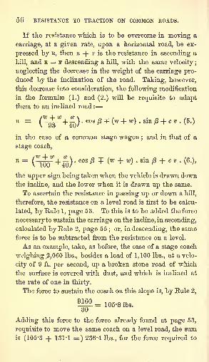
50 RESISTANCE TO TRACTION ON COMMON ROADS.
If the resistance which is to be overcome in moving a
carriage, at a given rate, upon a horizontal road, be ex-
pressed by K, then E + F is the resistance in ascending a
hill, and B F descending a hill, with the same velocity ;
neglecting the decrease in the weight of the carriage pro-
duced by the inclination of the road. Taking, however,
this decrease into consideration, the following modification
in the formula) (1.) and (2.) will be requisite to adaptthem to an inclined road :
in the case of a common stage wagon ;and in that of
stage coach,
the upper sign being taken when the vehicle is drawn downthe incline, and the lower when it is drawn up the same.
To ascertain the resistance in passing up or down a hill,
therefore, the resistance on a level road is first to be calcu-
lated, by Kule 1, page 53. To this is to be added the force
necessary to sustain the carriage on the incline, in ascending,
calculated by Kule 2, page 55; or, in descending, the same
force is to be subtracted from the resistance on a level.
As an example, take, as before, the case of a stage coach
weighing 2,060 Ibs., besides a load of 1,100 Ibs., at a velo-
city of 9 ft. per second, up a broken stone road of which
the surface is covered with dust, and which is inclined at
the rate of one in thirty.
The force to sustain the coach on this slope is, by Kule 2,
1^-= 105-3 Ibs.
Adding this force to the force already found at page 53,
requisite to move the same coach on a level road, the sumis (105-3 + 131-1 =) 236-4 Ibs., for the force required to
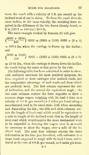
RULES FOR RESISTANCE. 57
move the coach with a velocity of 9 ft. per second up the
inclined road of one in thirty. To draw the coach down the
same incline, at the same velocity, the resulting force re-
quired is the difference of the two forces already found, or
it is (131-1 105-3=) 25-8 Ib,
The same example worked by formula (6) will give
(
2
j^j
1
) '9995 + (2060 + 1100) -0333 +(8x9)
= 236-3 Ibs, when the carriage is drawn up the incline;
and
'9995 ~ (206 + 110 >' 333 + (8 x 9
)
= 25-84 Ibs., when the carriage is drawn down the incline,
the result being the same as that given by the rule.
The following table has been calculated in order to show,
with sufficient exactness for most practical purposes, the
force required to draw carriages over inclined roads, and
the comparative advantage of such roads and those which
are perfectly level. The first column expresses the rate
of inclination, and the second the equivalent angle ;the
two next columns contain the force requisite to draw a
common stage wagon weighing with its load 6 tons, at a
velocity of 4*4 ft. per second (or 3 miles per hour) along a
macadamized road in its usual state, both when ascendingand descending the hill
;the fifth and sixth columns con-
tain the length of level road which would be equivalent to
a mile in length of the inclined road, that is, the length of
level road which would require the same mechanical work
to be expended in drawing the wagon over it, as would
be necessary to draw the wagon over a mile of the in-
clined road. The next four columns contain the same
information as the four just described, with reference to a
stage coach supposed to weigh with its load 3 tons, and to
travel at the rate of 8*8 ft. per second, or 6 miles per hour.
D 3
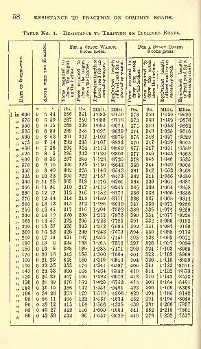
58 RESISTANCE TO TRACTION ON COMMON ROADS.
TABLE No. 4. RESISTANCE TO TRACTION ON INCLINED ROADS.
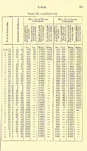
TABLE. 59
TABLE No. 4. (Continued.)
60 RESISTANCE TO TRACTION ON COMMON ROADS.
The foregoing table may be considered as affording a
view of the comparative disadvantage of hilly roads with
light and heavy traffic;the stage wagon weighing 6 tons
and travelling at the speed of 3 miles per hour, may be
taken as a fair average for goods traffic, and the stage
coach, weighing 3 tons and running 6 miles an hour, for
passenger traffic. It is shown that the resistance on hills
is much more unfavourable to the wagon than to the
coach. The force which would be requisite to move the
wagon on a level road would be 264 Ibs., and that to
move the coach 362 Ibs., being an excess of 98 Ibs. for the
traction of the coach. But, with a road inclined at the
rate of 1 in 600, this excess is only (373 286 =) 87 Ibs.;
and when the inclination of the road amounts to about
1 in 70, the forces required to draw them become equal.
As the inclination of the road increases beyond this, the
excess of force requisite to draw the waggon over that
necessary to move the coach, increases rapidly until, at an
inclination of 1 in 7, it amounts to (2162 1308 =)854 Ibs.
Comparing the forces required to draw either the wagonor the coach up and down any given incline, the former is
as much greater than the force required on a level road as
the latter is less. It might thence be concluded that, whena vehicle passes alternately each way along the road, no
real loss is occasioned by the inclination of the road, since
as much power is gained in the descent of the hill as is lost
in its ascent. Such is not, however, practically the fact,
for whilst it is necessary in the ascending journey to have
either a greater number of horses, or more powerful horses,
than would be requisite if the road were entirely level, no
corresponding reduction can be made in the descending
journey. There must be horses sufficient to draw the vehicle
along the level portions of the road; nor, generally speak-
ing, have the horses less to do in descending the hill,
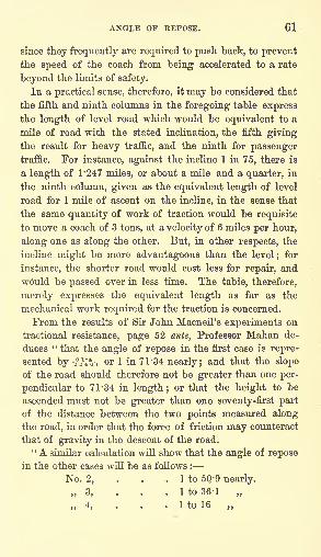
ANGLE OF REPOSE. 61
since they frequently are required to push back, to preventthe speed of the coach from being accelerated to a rate
beyond the limits of safety.
In a practical sense, therefore, it may be considered that
the fifth and ninth columns in the foregoing table expressthe length of level road which would be equivalent to a
mile of road with the stated inclination, the fifth givingthe result for heavy traffic, and the ninth for passengertraffic. For instance, against the incline 1 in 75, there is
a length of 1-247 miles, or about a mile and a quarter, in
the ninth column, given as the equivalent length of level
road for 1 mile of ascent on the incline, in the sense that
the same quantity of work of traction would be requisite
to move a coach of 3 tons, at a velocity of 6 miles per hour,
along one as along the other. But, in other respects, the
incline might be more advantageous than the level; for
instance, the shorter road would cost less for repair, and
would be passed over in less time. The table, therefore,
merely expresses the equivalent length as far as the
mechanical work required for the traction is concerned.
From the results of Sir John Macneil's experiments on
tractional resistance, page 52 ante, Professor Mahan de-
duces ' ' that the angle of repose in the first case is repre-
sented by-^j1;^-, or 1 in 71*34 nearly; and that the slope
of the road should therefore not be greater than one per-
pendicular to 71 '34 in length; or that the height to be
ascended must not be greater than one seventy-first part
of the distance between the two points measured alongthe road, in order that the force of friction may counteract
that of gravity in the descent of the road." A similar calculation will show that the angle of repose
in the other cases will be as follows :
No. 2, . . . 1 to 5Q-9 nearly.
,,3, . . . 1 to 36-1
,,4, . . . ItolG
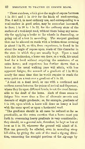
62 RESISTANCE TO TRACTION ON COMMON ROADS.
" These numbers, which give the angle of repose between.
1 in 36-1 and 1 in 50-9 for the kinds of road-covering,
Nos. 3 and 2, in most ordinary use, and corresponding to a
road-surface in good order, may be somewhat increased,
to from 1 in 28 to 1 in 33, for the ordinary state of the
surface of a well-kept road, without there being any neces-
sity for applying a brake to the wheels in descending, or
going out of a trot in ascending. The steepest gradient
that can be allowed on roads with a broken-stone covering
is about 1 in 20, as this, from experience, is found to be
about the angle of repose upon roads of this character in
the state in which they are usually kept. Upon a road
with this inclination, a horse can draw, at a walk, his usual
load for a level without requiring the assistance of an
extra horse;and experience has further shown that a
horse at the usual walking pace will attain, with less
apparent fatigue, the summit of a gradient of 1 in 20 in
nearly the same time that he would require to reach the
same point on a trot over a gradient of 1 in 33.
"A road on a dead level, or one with a continued and
uniform ascent between the points of arrival and departure,
where they lie upon different levels, is not the most favour-
able to the draft of the horse. Each of these seems to
fatigue him more than a line of alternate ascents and
descents of slight gradients ; as, for example, gradients of
1 in 100, upon which a horse will draw as heavy a load
with the same speed as upon a horizontal road.
"The gradients should in all cases be reduced as far as
practicable, as the extra exertion that a horse must putforth in overcoming heavy gradients is very considerable
;
they should, as a general rule, therefore, be kept as low at
least as 1 in 33, wherever the ground will admit of it.
This can generally be effected, even in ascending steep
hill-sides, by giving the axis of the road a zig-zag direc-
tion, connecting the straight portions of the zig-zags by
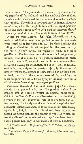
MAXIMUM GRADIENTS. 63
circular arcs. The gradients of the curved portions of the
zig-zags should be reduced, and the roadway also at these
points should be widened, for the safety of vehicles descend-
ing rapidly. The width of the road may be increased about
one-fourth, when the angle between the straight portions
of the ziz-zags is from 120 to 90;and the increase should
be nearly one-half where the angle is from 90 to 60."*
NOTE BY THE EDITOR. Sir John Macneil, in 1836,
maintained that no road was perfect unless its gradients
were equal to or less than 1 in 40. In thus limiting the
ruling gradient to 1 in 40, he justifies the assertion bythe much greater outlay for repair on roads of steeper
gradients. For instance, he adduces as a fact not generally
known, that if a road has no greater inclinations than
1 in 40, there is 20 per cent, less cost for maintenance than
for a road having an inclination of 1 in 20. The additional
cost is due not only to the greater injury by the action of
horses' feet on the steeper incline, which has already been
noticed, but also to the greater wear of the road by the
more frequent necessity for sledging or braking the wheels
of vehicles in descending the steeper portions.
Professor Mahan, it has been seen, page 62, recom-
mends, as a general rule, that the gradients should be
kept as low as 1 in 33;whilst M. Dumas, engineer-in-
chief of the French Ponts et Chaussees, writing in 1843,f
recommended, as a maximum rate of inclination, 1 in 50;
for, he says, "not only are the surfaces of steeply-inclined
roads subjected to abrasion by the feet of horses clambering
up the hill, but, in the intervals of rest, loose stones are
placed as props behind the wheels of vehicles, which are
usually allowed to remain where they have been tempo-
rarily placed, and may be the causes of serious accidents."
* "A Treatise on Civil Engineering," by D. H. Mahan, 2nd edition,
page 407.
t " Annales dts Ponta et Chaussees," 2nd series, 1 Semestre, 1843,
page 343.
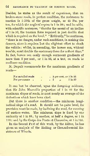
64 RESISTANCE TO TRACTION ON COMMON ROADS.
Besides, he states as the result of experience, that on
broken-stone roads, in perfect condition, the resistance to
traction is l-50th of the gross weight, or 45 Ibs. per
ton, for which the angle of repose is 1 in 50;and he adds,
with scientific acuteness,' ' that for the ascent of an incline
of 1 in 50, the traction force required is just double that
which is required on the level." "Evidently," he continues,
"there is no danger, under such conditions, in making the
descent, since it requires but the slightest effort to check
the vehicle; whilst, in ascending, the horses can, without
trouble, exert double the customary force for a short time."
In fact, horses can easily enough surmount gradients of
more than 3 per cent., or 1 in 33, at a trot, on roads in
mediocre condition.
M. Dupuit recommends for the maximum gradients of
roads
For metalled roads . . 3 per cent, or 1 in 33
For pavements . . .2 1 in 50
It can but be observed, upon the foregoing evidence,
that Sir John Macneil's proportion of 1 in 40 for the
maximum slopes of roads, is most nearly an average of the
deductions which have been cited.
But there is another condition the minimum longi-
tudinal slope of a road. It should not be quite level, for
provision must be made, by inclining the road, for runningoff surface-water. The minimum slope is fixed by one
authority at 1 in 80; by another, at half a degree, or 1 in
115;and by the Corps des Fonts et Chaussees, at 1 in 125.
In the Second Part of this work, by the Editor, he has
given an analysis of the Eolling or Circumferential Ee-
sistance of Wheels.
CHAPTER IV.
ON THE SECTION OF ROADS.
WHEKE hills or gradients are unavoidable, they should be
made as easy as possible ; and, although a certain amount
of additional power must be required to draw a carriage
up a hill, compared with the resistance on a level, yet so
long as the inclination is within a certain limit, the hilly
road may be considered as safe as a level road. This limit
depends upon the nature and condition of the surface of
the road, and it is attained in any particular case whenthe inclination of the road is made equal to the limiting
angle of resistance for the materials composing its surface;
that is, when it is such that a carriage once set in motion
on the road, would just continue its descent without anyadditional force being applied. When this limit is ex-
ceeded, the carriage descends with an accelerated velocity,
unless the horses or other force be employed to restrain
it; and, although, in such a case, the use of a drag, by
increasing the resistance, would in a measure obviate the
danger, yet the injury done to the surface of the road bythe use of the drag renders it desirable to avoid the use of
it altogether. The following table, taken from the second
volume of the "Eudiments of Civil Engineering," shows
the rate of inclination at which this limit is attained on
the various kinds of roads mentioned in the first column.
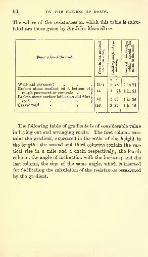
ON THE SECTION OF ROADS.
The values of the resistances on which this table is calcu-
lated are those given by Sir John Macneil :
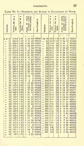
GRADIENTS. 67
TABLE No. 5. GRADIENTS AND ANGLES OF INCLINATION OF ROADS.
68 ON THE SECTION OF ROADS.
Width and Transverse Section of Roads. It is recom-
mended that roads should be wide. It is an error to
suppose that the cost of repairing a road depends entirely
upon the extent of its surface, and increases with its width.
The cost per mile of road depends more upon the extent
and the nature of the traffic;and it may be asserted,
generally, that the same quantity of material is necessaryfor the repair of a road, whether wide or narrow, subjected
to the same amount of traffic. On the narrow road, the
traffic, being confined very much to one track, the road
would be worn more severely than when the traffic is
spread over a larger surface. The expense of spreadingthe material over the wider road would be somewhat
greater, but the cost for material might be taken as
the same. One of the advantages of a wide road is, that
the air and the sun exercise more influence in keeping its
surface dry. The first cost of a wide road is certainly
greater than that of a narrow road, nearly in the ratio
of the widths.
For roads situated between towns of importance, and
exposed to much traffic, the width should not be less than
30 ft., which would admit of four vehicles abreast;besides
a footpath of 6 ft. In the immediate vicinity of large
towns and cities, the width should be greater.
The form of the cross section of a road is a subject of
much importance, and it is one upon which much difference
of opinion exists. Some persons advocate a considerable
degree of curvature in the upper surface of the road, with
the view of facilitating the drainage of its surface;whilst
others are averse to a road being much curved. It is the
practice of others, again, to form the road on a flat surface
transversely; whilst others give a dip to the formation-
surface each way from the centre, supposing that the
drainage of the road is thereby facilitated.
The only advantage resulting from the curving of the
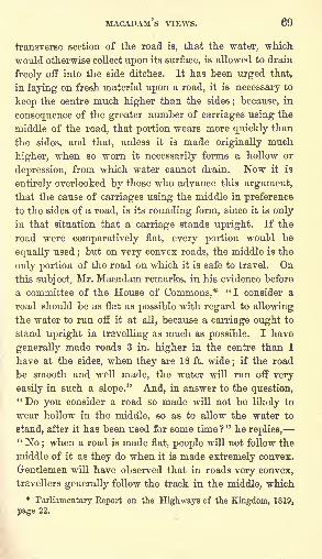
MACADAM'S VIEWS. 69
transverse section of the road is, that the water, which
would otherwise collect upon its surface, is allowed to drain
freely off into the side ditches. It has been urged that,
in laying on fresh material upon a road, it is necessary to
keep the centre much higher than the sides; because, in
consequence of the greater number of carriages using the
middle of the road, that portion wears more quickly than
the sides, and that, unless it is made originally much
higher, when so worn it necessarily forms a hollow or
depression, from which water cannot drain. Now it is
entirely overlooked by those who advance this argument,that the cause of carriages using the middle in preference
to the sides of a road, is its rounding form, since it is only
in that situation that a carriage stands upright. If the
road were comparatively flat, every portion would be
equally used;but on very convex roads, the middle is the
only portion of the road on which it is safe to travel. Onthis subject, Mr. Macadam remarks, in his evidence before
a committee of the House of Commons,* "I consider a
road should be as flat as possible with regard to allowing
the water to run off it at all, because a carriage ought to
stand upright in travelling as much as possible. I have
generally made roads 3 in. higher in the centre than I
have at the sides, when they are 18 ft. wide; if the road
be smooth and well made, the water will run off very
easily in such a slope." And, in answer to the question," Do you consider a road so made will not be likely to
wear hollow in the middle, so as to allow the water to
stand, after it has been used for some time?" he replies," No
;when a road is made flat, people will not follow the
middle of it as they do when it is made extremely convex.
Gentlemen will have observed that in roads very convex,
travellers generally follow the track in the middle, which
*Parliamentary Report on the Highways of the Kingdom, 1819,
page 22.
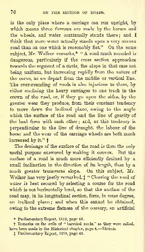
70 ON THE SECTION OF ROADS.
is the only place where a carriage can run upright, bywhich means three furrows are made by the horses and
the wheels, and water continually stands there;and I
think that more water actually stands upon a very convex
road than on one which is reasonably flat." On the same
subject, Mr. Walker remarks,* "A road much rounded is
dangerous, particularly if the cross section approaches
towards the segment of a circle, the slope in that case not
being uniform, but increasing rapidly from the nature of
the curve, as we depart from the middle or vertical line.
The over-rounding of roads is also injurious to them, byeither confining the heavy carriages to one track in the
crown of the road, or, if they go upon the sides, by the
greater wear they produce, from their constant tendencyto move down the inclined plane, owing to the angle
which the surface of the road and the line of gravity of
the load form with each other; and, as this tendency is
perpendicular to the line of draught, the labour of the
horse and the wear of the carriage wheels are both muchincreased by it." f
The drainage of the surface of the road is then the only
useful purpose answered by making it convex. But the
surface of a road is much more efficiently drained by a
small inclination in the direction of its length, than by a
much greater transverse slope. On this subject, Mr.
Walker has very justly remarked, J"Clearing the road of
water is best secured by selecting a course for the road
which is not horizontally level, so that the surface of the
road may, in its longitudinal section, form, in some degree,
an inclined plane ;and when this cannot be obtained,
owing to the extreme flatness of the country, an artificial
*Parliamentary Eeport, 1819, page 49.
t Kemarks on the evils of " barreled roads," as they were called,
have been made in the Historical chapter, page 4. EDITOR.
J Parliamentary Report, 1819, page 48.
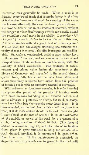
TRANSVERSE GRADIENTS. 71
inclination may generally be made. When a road is so
formed, every wheel-track that is made, being in the line
of inclination, becomes a channel for carrying off the water
much more effectually than can be done by a curvature in
the cross section or rise in the middle of the road, without
the danger or other disadvantages which necessarily attend
the rounding a road much in the middle. I consider a fall
of about 1| inches in 10 feet to be a minimum in this case,
if it is attainable without a great deal of extra expense."
Whilst, then, the advantages attending the extreme con-
vexity of roads is so small, the disadvantages are consider-
able. On roads so constructed, vehicles must either keepto the crown of the road, and so occasion an excessive and
unequal wear of its surface, or use the sides, with the
liability of being overturned. The evidence of coach-
masters and others, taken before the committee of the
House of Commons, and appended to the report already
quoted from, fully bears out the view here taken, and
shows that many accidents have arisen from the practice
of forming roads with an excessive amount of convexity.
With reference to the above remarks, it is only intended
to express disapproval of the practice of forming roads
with cross sections rounding in an extreme degree and
not to advocate a perfectly, or nearly, flat road, as many,who have fallen into the opposite error, have done. It is
recommended, as the best form which could be given to a
road, that its cross section should be formed of two straight
lines inclined at the rate of about 1 in 30, and connected
at the middle or crown of the road by a segment of a
circle, having a radius of about 90 feet. This form of
section is shown in Fig. 22, and the rate of inclination
there given is quite sufficient to keep the surface of a
road drained, provided it is maintained in good order,
free from ruts. If the maintenance is neglected, no
degree of convexity which can be given to the road will
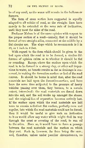
72 ON THE SECTION OF ROADS.
be of any avail, as the water will remain in the hollows or
furrows.
The form of cross section here suggested is equally
adapted to all widths of road, as the straight lines have
merely to be extended at the same rate of inclination,
until they meet the sides of the road.
Professor Mahan is of the same opinion with respect to
the proper section of a road namely, that it should be
formed of two straight sides, connected at the middle by a
flat circular arc. The slope which he recommends is 1 in
48, or 1 inch in 4 feet.
With regard to the form which should be given to the
bed upon which the road is to be formed, a similar dif-
ference of opinion exists as to whether it should be flat
or rounding. Except where the surface upon which the
road is to be formed is a strong clay, or other soil imper-vious to water, no benefit results as far as drainage is con-
cerned, in making the formation-surface or bed of the road
convex. It should be borne in mind that, after the road
materials are laid upon the formation-surface, and have
been for some time subjected to the pressure of heavyvehicles passing over them, they become, to a certain
extent, intermixed : the road materials are forced downinto the soil, and the soil works up amongst the stones,
and the original line of separation becomes entirely lost.
If the surface upon which the road materials are laid
were to remain a distinct flat surface, perfectly even and
regular, into which the road materials could not be forced,
then it would be useful to give such an inclination
to it as would allow any water which might find its waythrough the crust or covering of the road, to run off
to the sides. Even so, it would have to force a passagebetween the road materials and the surface on which
they rest. Such is, however, far from being the case;
and, therefore, unless under peculiar circumstances, no
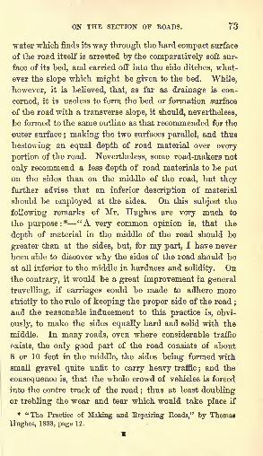
ON THE SECTION OF ROADS. 73
water which finds its way through the hard compact surface
of the road itself is arrested by the comparatively soft sur-
face of its bed, and carried off into the side ditches, what-
ever the slope which might be given to the bed. While,
however, it is believed, that, as far as drainage is con-
cerned, it is useless to form the bed or formation surface
of the road with a transverse slope, it should, nevertheless,
be formed to the same outline as that recommended for the
outer surface; making the two surfaces parallel, and thus
bestowing an equal depth of road material over every
portion of the road. Nevertheless, some road-makers not
only recommend a less depth of road materials to be puton the sides than on the middle of the road, but they
further advise that an inferior description of material
should be employed at the sides. On this subject the
following remarks of Mr. Hughes are very much to
the purpose:* "A very common opinion is, that the
depth of material in the middle of the road should be
greater than at the sides, but, for my part, I have never
been able to discover why the sides of the road should be
at all inferior to the middle in hardness and solidity. Onthe contrary, it would be a great improvement in general
travelling, if carriages could be made to adhere more
strictly to the rule of keeping the proper side of the road;
and the reasonable inducement to this practice is, obvi-
ously, to make the sides equally hard and solid with the
middle. In many roads, even where considerable traffic
exists, the only good part of the road consists of about
8 or 10 feet in the middle, the sides being formed with
small gravel quite unfit to carry heavy traffic;and the
consequence is, that the whole crowd of vehicles is forced
into the centre track of the road;thus at least doubling
or trebling the wear and tear which would take place if
* "The Practice of Making and Repairing Roads," by Thomaa
Hughes, 1838, page 12.
X
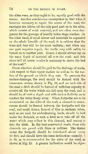
i 4 ON THE SECTION OF ROADS.
tlie sides were, as they ought to be, equally good with the
centre. Another mischievous consequence is, that when it
becomes necessary to repair the centre of the road, the
carriages are driven off the only good part on to the sides,
which consist of weak material, and are often even dan-
gerous for the passage of heavily-laden stage coaches. Onthe other hand, if equal labour and materials be expendedon the whole breadth of the road, it is evident that the
wear and tear will be far more uniform;and when any
one part requires repair, the traffic may with safety be
turned on to another part. Hence, I should always lay on
the same depth of material all over the road : and this
alone will of course render it necessary to curve the bed
of the road."
Great attention should be paid to the drainage of roads,
with respect to their upper surface as well as to the sur-
face of the ground on which they rest. To promote the
surface-drainage, the road should be formed with the
transverse section shown in Fig. 22, and on each side of
the road a ditch should be formed of sufficient capacity to
receive all the water which can fall upon the road, and it
should be of such a depth and with such a declivity as to
conduct the water freely away. When footpaths are to be
constructed on the sides of the road, a channel or water-
course should be formed between the footpaths and the
road, and small drains, formed of tiles or earthern tubes,
such as are used for underdraining lands, should be laid
under the footpath, at such a level as to take off all the
water which may collect in this channel, and convey it
into the ditch. In the best- constructed roads, these side
channels are paved with flints or pebbles. The drains
under the footpath should be introduced about every
60 feet, and should have the same inclination namely, t
in 30, as is recommended for the sides of the road, as
shown in Fig. 22. A greater inclination would be objec-
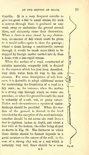
ON THE SECTION OF ROADS. 75
tionable. It is a very frequent mistake to
give too great a fall to small drains, for such
a current through them is produced as maywash away or undermine the ground around
them, and ultimately cause their destruction.
When a drain is once closed by any obstruc-
tion, no amount of fall which could be given
to it would suffice again to clear the passage ;
whilst a drain having a considerable current
through it, would be much more likely to be
stopped by foreign matter carried into it, than
a drain with a less rapid stream.
When the surface of a road, constructed of
suitable materials, compactly laid, is drained
in the manner which has just been described,
very little water finds its way to the sub-
stratum. For some descriptions of soil, how-
ever, it is desirable to adopt additional means
for maintaining the foundation of a road in a
dry state; as, for instance, when the surface
is a strong clay through which no water can
percolate, or when the ground beneath the road
is naturally of a soft, wet, or peaty nature
Under such circumstances a species of under-
drainage should be provided. When the sur-
face of the ground is formed to the level
intended for the reception of the road materials,
trenches should be cut across the road from a
foot to eighteen inches in depth, and about a
foot wide at the bottom, the sides being slopedas shown in Fig. 23. The distances at which
these drains should be formed depends in a
great measure on the nature of the soil;in the
case of a strong clay soil, or a soil which is
naturally very wet, there should be a cross
E2
i