the completion of the mathematical model by...
TRANSCRIPT

INCAS BULLETIN, Volume 7, Issue 3/ 2015, pp. 25 – 37 ISSN 2066 – 8201
The completion of the mathematical model by parameter
identification for simulating a turbofan engine
Irina Carmen ANDREI*,1
, Mihai Victor PRICOP1,
Mihai Leonida NICULESCU1, Andreea CERNAT
1
*Corresponding author 1INCAS − National Institute for Aerospace Research “Elie Carafoli”,
Flow Physics Department, Numerical Simulation Unit,
B-dul Iuliu Maniu 220, Bucharest 061126, Romania
[email protected]*, [email protected], [email protected],
DOI: 10.13111/2066-8201.2015.7.3.3
Received: 28 May 2015 / Received in revised form: 23 June 2015 / Accepted: 23 August 2015
Copyright©2015 Published by INCAS. This is an open access article under the CC BY-NC-ND
license (http://creativecommons.org/licenses/by-nc-nd/4.0/)
3rd
International Workshop on Numerical Modelling in Aerospace Sciences, NMAS 2015,
06-07 May 2015, Bucharest, Romania, (held at INCAS, B-dul Iuliu Maniu 220, sector 6)
Section 1 – Launchers propulsion technologies and simulations of rocket engines
Abstract: The purpose of this paper is to set up a method to determine the missing engine design
parameters (turbine inlet temperature T3T, airflow rate) which significantly influence the jet engines
thrust. The authors have introduced a new non-linear equation connecting the fan specific work with
the temperature T3T, customized for turbofan. The method of chords, since it converges
unconditionally, has been used for solving the non-linear equation of variable temperature T3T. An
alternate method, based for the same relation between fan specific work and T3T, has been presented
in purpose to determine airflow rate and fan pressure ratio. Two mixed flows turbofans have been
considered as study cases. For case #1 it was determined a value comparable to the Turbomeca
Larzac turbofan series 04-C6 and 04-C20 which power the AlphaJet machines (series A - Luftwaffe,
series E - Dassault Dornier). For the F100-PW229 turbofan, as case #2, being given T3T, then have
been determined the airflow rate, fan pressure ratio and fan specific work. After completing the
mathematical model with the missing parameters, the performances of the engines at off-design
regimes and the operational envelopes revealing i.e. the variations of thrust, specific thrust and fuel
specific consumption with altitude and Mach number have been calculated.
Key Words: turbofan, engine parameters, performances, off-design regimes, operating maps,
numerical simulation
1. INTRODUCTION
1.1 Justification of the study
In prediction and simulation of jet engine operation, as well as in performance calculation at
design and off-design regimes, input data (as engine's and fluid parameters) must be known.
Some parameters are given in catalogues or technical specifications of the manufacturers
(e.g. Pratt & Whitney [1], Jane's All the World's Aircraft, [2]), while others are not revealed
to public access. For most of the cases, there are given the airflow, pressure ratio, by-pass

Irina Carmen ANDREI, Mihai Victor PRICOP, Mihai Leonida NICULESCU, Andreea CERNAT 26
INCAS BULLETIN, Volume 7, Issue 3/ 2015
ratio and the values of the performances (as the thrust and fuel specific consumption) at Sea
Level Static SLS take off T/O and cruise conditions. In certain cases, the turbine inlet
temperature T3T might be specified, but for many other types of jet engines it is not
announced. Other parameters, like pressure losses along the fixed parts of the engine,
efficiencies on compression and expansion in turbine respectively are never exposed. Neither
the hypothesis regarding the gas as a single fluid or a mixture of species, and/or their
properties are specified. For these reasons and to complete the mathematical model of any jet
engine, as depicted in Fig. 1, identifying the missing parameters is very important.
The general group of the jet engines, Fig. 1, comprises: a/ the turbojets, b/ turbofans -
(b.1/ - with separate flows, for general civil applications; and b.2/ - with mixed flows, for
military use), c/ turboprops and d/ turbo-shafts.
(a) the turbojet (b) the turbofan (c) the turboprop (d) the turboshaft
Fig. 1 Types of jet engines, [3-4]
1.2 Goal and prospective
The goal of this paper is to identify a missing parameter that is the turbine inlet
temperature*
3T [K] (also denoted as T3T in international literature, e.g.: Cohen [5], Mattingly
[6], Baig [7]) in case of Turbofan # 1 and to determine the airflow rate for the F100-PW229
engine, both constructions being mixed flows turbofans MFTE.
The prospective refers to the numerical simulation of the MFTE, following the
completion of its mathematical model. The ultimate purpose is to obtain the operating maps
of the engine (depicting the variation of the performances: thrust, specific thrust and specific
fuel consumption TSFC, with altitude, flight velocity and engine speed). As a conclusion for
the motivation of this study, the completion of the mathematical model and numerical
simulation of turbofan engine form the basis for future CFD simulations.
1.3 Some issues on turbofan engines
The main design parameters airflow aM [kg/s] and pressure ratio
*
c and sometimes the
turbine inlet temperature T3T are given in catalogues for most types of jet engines. The
bypass ratio K is another design parameter, related only to turbofans, and it is often specified
(as in refs. [1-2]). Fora large number of turbofan families, the temperature T3T is not
announced. Other design parameters (such as pressure losses in air intake and combustor,
exit nozzle velocity loss, adiabatic efficiencies on compression and extension, mechanical
efficiency) are not exposed. The general approach to determine the missing design
parameters is to search combinations and then trim, until a match with the values of the
thrust and specific fuel consumption is obtained for take-off and cruise regimes. Following
this path means an extremely time-consuming process, sometimes the numerical accuracy is
not satisfactory and for certain cases the procedure does not converge. The airflow, pressure
ratio and turbine entry temperature T3T, as the main design parameters are focused, since the
performances of the engine are highly influenced by them. The influence on the engine
performances of the remaining design parameters listed in Table 1 is less in comparison with
the main ones. A more efficient approach is the one proposed by the authors, which consists
27 The completion of the mathematical model by parameter identification for simulating a turbofan engine
INCAS BULLETIN, Volume 7, Issue 3/ 2015
in the determination of the temperature T3T by using a customized in-house developed
method and then the trimming of design parameters expressing losses and efficiencies. The
method developed by the authors in order to identify the temperature T3T results from the
considerations regarding the mixing the core gas flow (i.e. the mainstream flow) and the
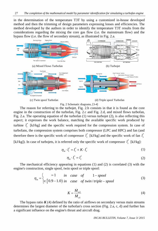
bypass flow (i.e. the flow of secondary stream), as illustrated in Fig. 2.a.
(a) Mixed Flows Turbofan (b) Turbojet
(c) Twin spool Turbofan (d) Triple spool Turbofan
Fig. 2 Schematic diagrams, [3-4]
The reason for referring to the turbojet, Fig. 2.b consists in that it is found as the core
engine in the construction of the turbofan, Fig. 2.c and Fig. 2.d, and mixed flows turbofan,
Fig. 2.a. The operating equation of the turbofan (1) versus turbojet (2), is also reflecting this
aspect; it expresses the work balance, matching the available specific work produced by
turbine *
tl [kJ/kg] and the specific work required for the compression system. In case of
turbofans, the compression system comprises both compressor (LPC and HPC) and fan (and
therefore there is the specific work of compressor *
cl [kJ/kg] and the specific work of fan *
vl
[kJ/kg]). In case of turbojets, it is referred only the specific work of compressor *
cl [kJ/kg]:
* * *
m t c vl l K l (1)
* *
m t cl l (2)
The mechanical efficiency appearing in equations (1) and (2) is correlated (3) with the
engine's construction, single spool, twin spool or triple spool:
1
0.9 1.0m
1
/
in case of spool
in case of twin triple spool
(3)
2
1
a
a
MK
M (4)
The bypass ratio K (4) defined by the ratio of airflows on secondary versus main streams
determines the largest diameter of the turbofan's cross section (Fig. 2.a, c, d) and further has
a significant influence on the engine's thrust and aircraft drag.

Irina Carmen ANDREI, Mihai Victor PRICOP, Mihai Leonida NICULESCU, Andreea CERNAT 28
INCAS BULLETIN, Volume 7, Issue 3/ 2015
2. THE STUDY CASES
Threemixed flows turbofan engines (as constructions shown in Fig. 2.a) can be considered as
study cases, of which one is manufactured by Honeywell and the other two are the F100-
PW220 and F100-PW229 manufactured by Pratt & Whitney. Table 1 details a list of
turbofan engine design parameters, as results from a Honeywell Overview [8] and Pratt &
Whitney [1] open source.
Tables 2, 3 and 4 contain input data that are required for the performance prediction (at
design and off-design regimes), RTO [9], Baig[7] and engine numerical simulation RTO [9],
Reed, Turner, Norris and Veres [10].
In order to highlight the specific aspects of the methodology exposed in this paper, this
study will focus on two cases: the Turbofan # 1 and F 100-PW 229 engines.
As regards the F100-PW220 engine (a version of which evolved the F 100-PW 229
turbofan engine, although the temperature T3T being not exposed, their values for the two
versions are close), the differences between the thrust (i.e. military thrust and thrust with
afterburner) are due to the significant modification of overall pressure ratio (meaning
additional axial compressor stages) and of bypass ratio (or equivalent airflow rate) in order
to increase the thrust.
For these reasons, the focus is on the Turbofan # 1 as test case for determining the
temperature T3T and the F100-PW229 engine as test case for calculating the airflow rate.
Table 1 - Main design parameters of the turbofan engines, Honeywell [8], Pratt & Whitney [1]:
Engine reference Turbofan # 1 F100-PW229
F100-PW220
Manufacturer Honeywell Pratt & Whitney
Pratt & Whitney
Overall Pressure Ratio *
c = 22 *
c = 32 *
c = 25
Fan Pressure Ratio *
v = 1.76
- not announced - not announced
Bypass Ratio BPR K=2.9 K=0.36 K=0.63
Overall Airflow Rate [kg/s] aM = 65.772 - not announced - not announced
Turbine inlettemperature T3T [K] - not announced 1623 - not announced
Maximum Thrust F [kN] military
thrust // with afterburner
≈ 20.91 // without
afterburner 77.5 // 129.7 64.9 // 105.7
Table 2 - The performances of Turbofan # 1, as reference values, [8]:
Conditions // regimes Net thrust [N]
Fuel specific
consumption
[kg/Nh]
Thermodynamic, Sea Level, Static SLS, International
Standard AtmosphereISA, [10] 20907 0.04650
Takeoff, Sea Level, Static (available to 303 [K]) 18905 0.04660
Max Cruise, Mach 0.8 (ISA), 40000[ft] = 12.19 [km] 4493 0.07536
Table 3 - Altitude levels, [8]:
H [ft] 0 10000 20000 30000 40000
H [km] 0 3.048 6.096 9.144 12.192
Table 4 - Mach numbers, [8]:
Mach number at Sea Level Static SLS 0.0
Mach number at Cruise 0.7
Mach number at Max Cruise 0.8
29 The completion of the mathematical model by parameter identification for simulating a turbofan engine
INCAS BULLETIN, Volume 7, Issue 3/ 2015
3. MATHEMATICAL SUPPORT
The development of the mathematical support is oriented towards the obtaining the equation
and the method for the identification of the turbine inlet temperature T3T, since this
parameter has a significant influence upon the performances of the engine.
In case of the mixed flows turbofan presented in Fig. 2.a, the mixing conditions (i.e.
either the relations (5) and (6) or both (5) and (7)) that are imposed to the main and
secondary streams allow the obtaining for the equation in question.
Technically, the mixing conditions refer to the fact that both streams arrive in the
mixing area with equal absolute velocities (5) and either equal static pressures (6) or
stagnation pressures (7), Pimsner [11], Rotaru [12], Ciobotea [13], Stanciu [14-15]. The
condition of equally stagnation pressures (7) allows in a greater extent the obtaining of
minimal pressure losses, rather than the condition of equal static pressures (6), being
assumed that the pressure loss coefficients for both streams can be considered equal:
4 2vC C (5)
4 2vp p (6)
* *
4 2vp p (7)
The ratio of turbine inlet versus exit stagnation pressure is defined as the turbine
expansion ratio TER *
t (8), which further is expressed by relations (9) and (10), where the
specific work of turbine is given by equation (1).
Then, the stagnation pressure at turbine exit *
4p is expressed (8') as a function of the
turbine expansion ratio TER *
t (10) and eventually as function (11) of the stagnation
pressure at turbine inlet *
3p [bar], the specific work of compressor *
cl (13) and fan *
vl (14),
bypass ratio K and turbine inlet specific enthalpy *
3i [kJ/kg]. The stagnation pressures at aft
fan *
2vp (12) are expressed as a function of the specific work of fan *
vl (14) and inlet
parameters, namely inlet stagnation pressure *
1p [bar], and inlet stagnation specific enthalpy
*
1i [kJ/kg]:
** 3
*
4
t
p
p (8)
'
* ' 1*
* *
3
1
k
kt
t
t
l
i
(9)
' '
* * * *' 1 ' 1*
* * * *
3 3
1 1
k k
k kc v c v
t
m t t
l K l l K l
i i
(10)

Irina Carmen ANDREI, Mihai Victor PRICOP, Mihai Leonida NICULESCU, Andreea CERNAT 30
INCAS BULLETIN, Volume 7, Issue 3/ 2015
** 34 *
t
pp
(8′)
* * 1* *
4 3 * *
3
1
g
g
k
kc v
t
l K lp p
i
(11)
* * 1* *
2 1 *
1
1
k
kv v
v
lp p
i
(12)
* 1
* *
1 *
1k
kc
c
c
l i
(13)
* 1
* *
1 *
1k
kv
v
v
l i
(14)
Further, the stagnation pressure at turbine inlet *
3p is expressed (15) as a function of
upstream parameters, being highlighted the combustor pressure loss *
ca , compressor
pressure ratio *
c and inlet stagnation pressure *
1p .
Likewise, stagnation pressure at fan exit (16) is expressed by the means of the fan
pressure ratio *
v and inlet stagnation pressure *
1p :
* ** * * * *3 23 1 1* *
2 1
ca c
p pp p p
p p (15)
** * * *22 1 1*
1
vv v
pp p p
p (16)
Eventually, for the stagnation pressure aft turbine *
4p the relation (17) is obtained:
* * 1* * * *
4 1 * *
3
1
g
g
k
kc v
c ca
t
l K lp p
i
(17)
The mixing condition (7) signifying the equality between the stagnation pressure aft
turbine*
4p (17) and stagnation pressure aft fan*
2vp (12), generates a non-linear equation (18)
that can be simplified (19), showing that the inlet stagnation pressure *
1p does not influence
at all the turbine inlet temperature T3T:

31 The completion of the mathematical model by parameter identification for simulating a turbofan engine
INCAS BULLETIN, Volume 7, Issue 3/ 2015
* * * *1 1* * * *
1 1* * *
3 1
1 1
g
g
k k
k kc v v v
c ca
t
l K l lp p
i i
(18)
* * * *1 1* *
* * *
3 1
1 1
g
g
k k
k kc v v v
c ca
t
l K l l
i i
(19)
Further, an equivalent form (20) of relation (19) that allows the calculation of the turbine
entry temperature T3T is deduced after applying the function ln(x). The original
contributions provided by the authors are the obtaining of a new relation (20) and the
demonstration that its associated algorithm (27) converges faster for obtaining highly
accurate numerical solutions.
* * * *
* *
* * *
3 1
ln ln 1 ln 11 1
g c v v vc ca
g t
k l K l k l
k i k i
(20)
Both equations (19) and (20) expressing the turbine inlet temperature T3T can be solved
numerically as non-linear equations, with appropriate methods, such as: the method of
chords or the method of tangents, Carnahan [16], Spelucci [17], Hjorth-Jensen [18],
Berbente [19-20].
4. METHODOLOGY FOR NUMERICAL APPROACH
The method of chords is to be considered for obtaining the numerical solutions with high
accuracy and unconditioned convergence (unlike the method of tangents, which is oscillating
and does not converge for steepest slopes and requires the modification of the starting point).
In order to prepare for the application of the numerical algorithm (27) specific to the method
of chords, both equations (19) and (20) can be written of the form (21); therefore, relation
(22) is the equivalent form of the equation (19) and relation (23) is the equivalent of (23):
0f x (21)
* * * *1 1
* * *
* * *
3 1
1 1
g
g
k k
k kc v v v
v c ca
t
l K l lfp l
i i
(22)
* * * *
* * *
* * *
3 1
ln ln 1 ln 11 1
g c v v vv c ca
g t
k l K l k lf l
k i k i
(23)
The argument of both functions f (23) and fp (22) is the specific work of fan *
vl ; the fan
pressure ratio *
v comes up from equation (24), which was deduced from (14):
1*
* *
*
1
1
k
kv
v v
l
i
(24)

Irina Carmen ANDREI, Mihai Victor PRICOP, Mihai Leonida NICULESCU, Andreea CERNAT 32
INCAS BULLETIN, Volume 7, Issue 3/ 2015
Since there is a single non-linear equation (22) or equivalent (23) with two parameters
(the temperature T3T and the specific work of fan *
vl ),the non-determination is off if one
parameter is set to a certain reference value (in this case, the temperature T3T) and the other
is obtained numerically. Technically, the approach for numerical searching is done according
to the next steps, proposed by the authors:
1. Setting the temperature T3T, by considering as reference the values for known
similar turbofan constructions, e.g.: T3T [K] = 1175// 1275 Viper 631/633// 1300/
1375/ 1403 of the Larzac 04-C6 turbofan powering the French trainer version
AlphaJet-E, 1433 - for the more powerful Larzac 04-C20 turbofans refitted for the
attack version of the Luftwaffe AlphaJet-A machines/ 1800 Eurofighter/ 1850
Rafale, as focused below in Table 5, first column:
Table 5. Solutions of the function f (23)- for large range T3T intervals
*
3T K * /vl kJ kg *
v
1175 34.576 1.4032669
1275 45.644 1.55375834
1300 48.317 1.59175686
1375 56.121 1.70650774
1403 58.955 1.74960491
1433 61.946 1.79591531
1800 95.065 2.3691199
1850 99.135 2.44756941
1900 103.11 2.52597691
2. For a presumed value of the temperature T3T [K], as specified above, there can be
set a searching closed interval for the specific work of fan *
vl , as the argument (25)
of the functions (22) and (23), ranging from 20 up to 80 [kJ/kg]; for the values of the
T3T temperature higher than 1500 [K], the searching interval can be enlarged, from
20 up to 110 [kJ/kg].
3. The numerical solutions of equations (22) and (23), which represent the specific
work of fan *
vl , are obtained with the algorithm (27) related to the method of chords,
Carnahan [16], Spelucci [17], Berbente [19-20].The calculated values of the specific
work of fan as the solutions of the non-linear equation (22) or equivalent (23) are
summarized in the second column of Table 5.
4. Once the specific work of fanbeing determined (with high numerical accuracy, due
to the specificity of the method of chords, [16-20], and as shown in Table 6, for a
search session, with the presumed T3T = 1300 [K]); then, from relation (24), the fan
pressure ratio *
v is calculated, see Table 5, the third column.
5. The search is continued until the calculated fan pressure ratio reaches the value
specified for the fixed point, which is 1.76:
*
vx l (25)
*( ) ( )vf x f l (26)
1 1
1
n
n n n n
n n
f xx x x x
f x f x
(27)
33 The completion of the mathematical model by parameter identification for simulating a turbofan engine
INCAS BULLETIN, Volume 7, Issue 3/ 2015
0
1
20
80
x
x
(28)
1,2,....n (29)
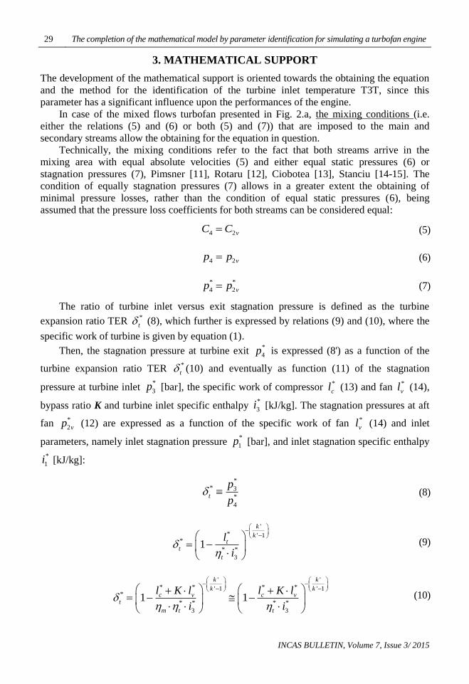
5. RESULTS AND CONCLUSIONS
The variation of the functions f (23)- in red contours and fp (22)– in blue contours, for both
study cases is plotted in Fig. 3. The graphic shown in Fig. 3-acorresponds to the setting of
the turbine inlet temperature T3T = 1300 [K] with the resulting specific work of fan *
vl =
48.31698762 [kJ/kg] and fan pressure ratio *
v = 1.59175686. For the same T3T setting have
been obtained the iterations sequences given by the algorithm (27), for both functions f (23)
and fp (22), and exposed below. The non-linear feature of the function f (23) is highlighted
much more in Fig. 3-b.
(a) - Case of Turbofan # 1 (b) - Case of F100-PW229 turbofan
Fig. 3 Functions f (23) and fp (22) of argument fan specific work *
vl [kJ/kg]
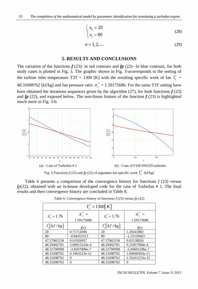
Table 6 presents a comparison of the convergence history for functions f (23) versus
fp(22), obtained with an in-house developed code for the case of Turbofan # 1. The final
results and their convergence history are concluded in Table 8.
Table 6. Convergence history of functions f (23) versus fp (22)
*
3 1300T K
* 1.76v
*
v =
1.59175686
* 1.76v
*
v =
1.59175686
* /vl kJ kg f(x)
* /vl kJ kg f(x)
20 0.71714306 20 1.29241882
80 -0.84352313 80 -1.23120663
47.57065158 0.01926957 47.57065158 0.03138826
48.29492701 5.69915319e-4 48.29492701 9.25957994e-4
48.31700098 -3.4507008e-7 48.31700098 -5.60601596e-7
48.31698762 6.1963213e-12 48.31698762 1.00668363e-11
48.31698762 0 48.31698762 1.55431223e-15
48.31698762 0 48.31698762 0

Irina Carmen ANDREI, Mihai Victor PRICOP, Mihai Leonida NICULESCU, Andreea CERNAT 34
INCAS BULLETIN, Volume 7, Issue 3/ 2015
The solution was obtained with 11 significant digits, which means high accuracy, of
order 10^(-12)
, after seven iterations when using the function f (23) and after eight iterations
for the function fp (22). Therefore, the method of chords converges faster and provides
numerical accuracy higher with one order, when using the function f (23).
So far, there can be highlighted some relevant remarks for the methodology and
numerical approach:
1. the use of method of chords, since it provides highly accurate solutions and
converges unconditioned;
2. the use of the function f (23) rather than the function fp (22), since the results are
obtained with less iterations;
3. the two parameters (the temperature T3T and the specific work of fan *
vl ), that
appear inside the non-linear equation (23) as well as (22), can be determined
numerically, following a step-by-step procedure, as introduced above, which
consists in setting a reference value for the temperature T3T and then calculating the
specific work of fan as the limit of the convergent sequence (27) and the fan pressure
ratio from equation (24).
4. Since the fan pressure ratio at fixed point is 1.76, as given in ref. [8], one can
conclude also that the searching interval for the turbine inlet temperature, ranging
from 1175 [K] up to 1900 [K], see Table 5, can be significantly narrowed to the
range 1403 [K] up to 1433 [K], see Table 7.
The value T3T=1403[K] corresponds to the Larzac 04-C6 turbofan powering the
French trainer version AlphaJet-E and T3T=1433[K] is for the more powerful Larzac 04-
C20 turbofan refitted for the attack version of the Luftwaffe AlphaJet-A machine.
Table 7. Solutions of the function f (23) - for narrowed range T3T intervals
*
3T K * /vl kJ kg *
v
1403 58.955 1.74960491
1410 59.657 1.760399 ≈ 1.76
1433 61.946 1.79591531
In conclusion, there has been determined the value of the turbine inlet temperature T3T
= 1410 [K], such that the calculated fan pressure ratio is 1.760399 ≈ 1.76 matches the value
specified for the fixed point, which is 1.76, as specified in ref. [8], with the matching value
of the specific work of fanbeing calculated as 59.657 [kJ/kg].
In Table 8 is presented the convergence history for three values of temperature, namely
T3T = 1403 [K], 1410 [K] and 1433 [K], corresponding to the narrowed searching interval.
The solutions of the non-linear equation (23) of argument *
vx l (25) that is the fan specific
work, are obtained with 14 significant digits after 7 iterations and after another iteration, the
numerical accuracy has been improved with two more orders, i.e. the 16 significant digits
have been obtained;
Table 8. Convergence history and final results
*
3 1403T K *
3 1410T K *
3 1433T K
* 1.76v
1.74960491
* 1.76v
1.760399 ≈ 1.76
* 1.76v
1.79591531
* /vl kJ kg f(x) * /vl kJ kg f(x) * /vl kJ kg f(x)
20 0.9161455 20 0.92829367 20 0.96712693
80 -0.51281138 80 -0.49296558 80 -0.42977795
58.467732 0.01169386 59.188924 0.01117993 61.540134 9.53214253e-3

35 The completion of the mathematical model by parameter identification for simulating a turbofan engine
INCAS BULLETIN, Volume 7, Issue 3/ 2015
58.947794 1.76622721e-4 59.65043 1.60274878e-4 61.940676 1.14163633e-4
58.955156 -5.57984042e-8 59.657142 -4.78878279e-8 61.945531 -2.80520026e-8
58.955154 2.65898414e-13 59.65714 2.06057393e-13 61.94553 8.12683254e-14
58.955154 1.44328993e-15 59.65714 0 61.94553 0
58.955154 0 59.65714 0 61.94553 0
Then, after the identification of all missing parameters and the completion of the
mathematical model, one can complete the next level, i.e. the determination of performances
at design regime and their prediction at off-design regimes, following the methodology
described in literature for the mixed flows turbofan, e.g. Cohen [5], Pimsner [11], Rotaru
[12], Ciobotea [13], Stanciu [14-15]. Further, the characteristics of the engine parts can be
calculated, Stoicescu and Rotaru [21], and optimizations of fan and compressor cascades,
Andrei [22], can be carried on.
After these steps, one can proceed to a higher level, which is the numerical simulation of
the turbofan engine operation and the calculation of the operating maps of the mixed flow
turbofan engine (i.e. the variation of the performances with altitude, velocity and engine
speed). All these calculations are based on the properties of working fluids: air, as detailed in
ref. [23]- Standard Atmosphere, gas and air-gas mixture.
The graphics shown below have been calculated for the case of Turbofan # 1. In Fig. 4
is plotted the variation with altitude and Mach number of the thrust F [N], in Fig. 5 - the
specific thrust Fsp [Ns/kg] and in Fig. 6 - fuel specific consumption Csp [kg/Nh].
Fig. 4 Variation of engine thrust F [N] with altitude and
Mach =0.7 (red contours), Mach = 0.8 (blue contours)
Fig. 5 Variation of specific thrust Fsp [Ns/kg]
with altitude and Mach =0.7 (red contours),
Mach = 0.8 (blue contours)
Fig. 6 Variation of specific fuel consumption Csp [kg/Nh] with altitude
and Mach =0.7 (red contours), Mach = 0.8 (blue contours)
Irina Carmen ANDREI, Mihai Victor PRICOP, Mihai Leonida NICULESCU, Andreea CERNAT 36
INCAS BULLETIN, Volume 7, Issue 3/ 2015
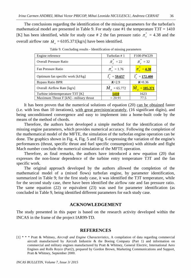
The conclusions regarding the identification of the missing parameters for the turbofan's
mathematical model are presented in Table 9. For study case #1 the temperature T3T = 1410
[K] has been identified, while for study case # 2 the fan pressure ratio *
v = 4.38 and the
overall airflow rate aM = 6105.371[kg/s] have been identified.
Table 9. Concluding results - Identification of missing parameters
Engine reference Turbofan # 1 F100-PW229
Overall Pressure Ratio *
c = 22 *
c = 32
Fan Pressure Ratio *
v = 1.76
*
v = 4.38
Optimum fan specific work [kJ/kg] *
vl = 59.657
*
vl = 172.400
Bypass Ratio BPR K=2.9 K=0.36
Overall Airflow Rate [kg/s] aM = 65.772
aM = 105.371
Turbine inlettemperature T3T [K] 1410 1623
Maximum Thrust F [kN] - military thrust ≈ 20.91 77.5
It has been proven that the numerical solutions of equation (20) can be obtained faster
(i.e. with less than 10 iterations), with great precision/acurately, (16 significant digits), and
being unconditioned convergence and easy to implement into a home-built code by the
means of the method of chords.
Therefore, the authors have developed a simple method for the identification of the
missing engine parameters, which provides numerical accuracy. Following the completion of
the mathematical model of the MFTE, the simulation of the turbofan engine operation can be
done. The graphics shown in Fig. 4, Fig. 5 and Fig. 6 expressing the variation of the engine's
performances (thrust, specific thrust and fuel specific consumption) with altitude and flight
Mach number conclude the numerical simulation of the MFTE operation.
Therefore, as final remarks, the authors have introduced a new equation (20) that
expresses the non-linear dependence of the turbine entry temperature T3T and the fan
specific work.
The original approach developed by the authors allowed the completion of the
mathematical model of a (mixed flows) turbofan engine, by parameter identification,
summarized in Table 9; for the first study case, it was identified the T3T temperature, while
for the second study case, there have been identified the airflow rate and fan pressure ratio.
The same equation (22) or equivalent (23) was used for parameter identification (as
concluded in Table 9, being identified different parameters for each study case.
ACKNOWLEDGEMENT
The study presented in this paper is based on the research activity developed within the
INCAS in the frame of the project IAR99-TD.
REFERENCES
[1] * * * Pratt & Whitney, Aircraft and Engine Characteristics, A compilation of data regarding commercial
aircraft manufactured by Aircraft Industrie & the Boeing Company (Part 1) and information on
commercial and military engines manufactured by Pratt & Whitney, General Electric, International Aero
Engines and Rolls Royce (Part2), prepared by Gordon Brown, Marketing Communications and Support,
Pratt & Whitney, September 2000.

37 The completion of the mathematical model by parameter identification for simulating a turbofan engine
INCAS BULLETIN, Volume 7, Issue 3/ 2015
[2] * * *IHS Jane's All the World's Aircraft 2013-2014: Development and Production, 104th Edition, Susan
Bushell (Compiler), David Willis (Compiler), Paul Jackson (Editor), ISBN-13: 978-0710630407, ISBN-
10: 07-10630409.
[3] * * * The Jet Engine, Rolls Royce plc, 5th Ed. 1986, Reprinted 1996 with revisions, ISBN 0-902121-2-35.
[4] * * * POWERPLANT, JAA ATPL Training, JEPPESEN, Atlantic Flight Training Ltd, ISBN 0-88487-355-2,
JA 310105-000.
[5] H. Cohen, G. F. C. Rogers, H. I. H.Saravanamuttoo, Gas Turbine Theory, 4 ed., Longman, Essex, 1989.
[6] J. D. Mattingly, Elements of Propulsion, Gas Turbines and Rockets, AIAA, Reston, VA, 2006.
[7] M. F. Baig, H. I. H.Saravanamuttoo, Off-Design Performance Prediction of Single Spool Turbojets Using
Gasdynamics, Journal of Propulsion and Power, vol. 13, no. 6, pp. 808-810, 1997.
[8] * * * TFE-731-40 Overview, Proven Turbofan Propulsion Technology, HONEYWELL.
[9] * * * RTO Technical Report 044, RTO-TR-044, AC/323 (AVT-018) TP/ 29, Performance Prediction and
Simulation of Gas Turbine Engine Operation (La prévision des performances et la simulation du
fonctionnement des turbomoteurs), 2002.
[10] J. A. Reed, M. G. Turner, A. Norris, J. P. Veres, Towards an Automated Full-Turbofan Engine Numerical
Simulation, Report NASA/ TM – 2003212494, August 2003, Prepared for the 16th International
Symposium on Air-breathing Engines, Cleveland, Ohio, August 31-September 5, 2003.
[11] V. Pimsner, Motoare aeroreactoare, Ed. Didactica si Pedagogica, Bucuresti, 1983.
[12] C. Rotaru, Theory of Turbojet Engines, Publishing House of Military Technical Academy, Bucharest, 1999.
[13] V. Ciobotea, Turboreactorul cu dublu flux, Ed. Academia Militara, Bucuresti, 1982.
[14] V. Stanciu, A. Miclescu, G. Mogos, Aplicatii ale teorieisistemelor de propulsieaeriene, Ed. Printech,
Bucuresti, 2005, ISBN 973-718-167-0.
[15] V. Stanciu, Bazele propulsiei aeronautice, Ed. Printech, Bucuresti, 2005, ISBN 978-606-521-894-9.
[16] B. Carnahan, H. A. Luther, J. O. Wilkes, Applied Numerical Methods, John Wiley, New York, 1969.
[17] P. Spellucci, Kurz-Skriptzur Vorlesung Einfűhrung in die Numerische Mathematik fűr Maschinenbau MB,
Ingenieurwissenschaften WI/MB, VI, Mechanik (BS), SS 2003, TechnischeUniversität Darmstadt,
http://numawww.mathematik.tu-darmstadt.de:8081.
[18] M. Hjorth-Jensen, Computational Physics, University of Oslo, Fall 2007.
[19] C. Berbente, O. Pleter, S. Berbente, Numerischemethoden. Theorie und Anwendungen, Ed. Printech,
Bucuresti, 2000.
[20] C. Berbente, S. Mitran, S. Zancu, Metode numerice, Ed. Tehnica, Bucuresti, 1997.
[21] M. Stoicescu, C. Rotaru, Turbojet engines. Characteristics and Control Methods, Publishing House of
Military Technical Academy, Bucharest, 1999.
[22] I. C. Andrei, Cercetari privind studiul curgerii prin retelele de palete de compresor axial si posibilitati de
îmbunatatire a performantelor, cu aplicatii la motoarele aeroreactoare / Andrei N. Irina Carmen. –
Bucuresti : Universitatea Politehnica Bucuresti, Facultatea de Inginerie Aerospatiala, 2007. - XXIV, 237
f.: fig.il. color + 1 CD-ROM, Teza de doctorat. Cond. stiintif.: prof. dr. ing. Corneliu Berbente
533.6(043.2), 621.51.001.5(043.2), 621.45(043.2), B-UP 1, Biblioteca U.P.B. inreg. nr. 043/3219.
[23] * * * U. S. Standard Atmosphere, U. S. Government Printing Office, Washington, D. C., Oct. 1976.
[24] * * * https://en.wikipedia.org/wiki/Pratt_%26_Whitney_F100.